CVC L ANTENNA GATES GATES RING. Designed for FM Stereo and Multiplex broadcasting Shunt Fed -Binary Adjustment (Pat. Pending).
|
|
|
- Logan Griffin
- 5 years ago
- Views:
Transcription


.")


1 GATES GATES CVC L O D FM RING ANTENNA Designed for FM Stereo and Multiplex broadcasting Shunt Fed -Binary Adjustment (Pat. Pending). Lowest possible VSWR Top, side or irside tower mounting Optional deicing with high or low power heaters Circularity db in free space Field- proven performance Minimum windloading High gain Directional patterns available


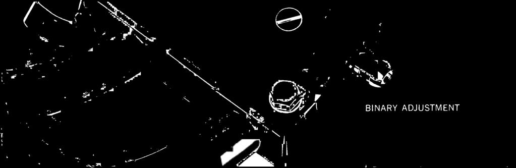
2 GATES CVCLDI D ANTENNA BINARY ADJUSTMENT
 HORIZONTAL PATTERN: Circular,! 1.0 db in free space. WEIGHT: 25 lbs. per ring. INPUT IMPEDANCE: 50 ohms, on 15/8\" or 3'/8\" coax.")
. Antenna elements as required. Interconnecting rigid coax 15/8\" or 31/8\" as ordered.")
 TYPE NUMBER FMA -1 FMA -2 FMA -3 FMA -4 FMA -5 FMA -6 FMA -7 NO. OF BAYS Field Gain.95 1.41 1.73 2.02 2.28 2.51 2.70 - FMA -8' 2.90 Power Gain.")
3 SPECIFICATIONS FREQUENCY RANGE: Factory tuned on customer's frequency in Mc band. POLARIZATION: Horizontal. DIMENSIONS (1 bay): Height (over -all) -6" Ring Diameter -approx. 18" (depends on frequency) HORIZONTAL PATTERN: Circular,! 1.0 db in free space. WEIGHT: 25 lbs. per ring. INPUT IMPEDANCE: 50 ohms, on 15/8" or 3'/8" coax. VSWR (without field tuning): Top Mounting -1.2 to 1. Side Mounting -1.5 to 1. VSWR (with field tuning): Top Mounting -1.1 to 1. Side Mounting -1.1 to 1. WINDLOAD: 20 lbs. per square foot. EQUIPMENT FURNISHED: Antenna Mounting hardware - (specify tower manufacturer). Antenna elements as required. Interconnecting rigid coax 15/8" or 31/8" as ordered. Standard EIA 15/8" or 31/8" flanges as ordered. ACCESSORY EQUIPMENT: De- icers: 200 watt -FMH watt-fm H-400 Power cable for heaters FIGURE 4. Horizontal Polarization Chart (side or top mounting) TYPE NUMBER FMA -1 FMA -2 FMA -3 FMA -4 FMA -5 FMA -6 FMA -7 NO. OF BAYS Field Gain FMA -8' 2.90 Power Gain Length in feet 6 in. 10 ft. 20 ft. 30 ft. 40 ft. 50 ft. 60 ft. 70 ft. Weight in lbs *Power and field gain of additional number of bays quoted upon request. 1. It is not advisable to use more than a 10 KW transmitter on 1W line or 20 KW on a 31/8" line. 2. Windloads are based on 20 pounds per sq. ft. on projected areas of cylindrical surfaces with all sections considered round. -, ORDERING INFORMATION 3. Power gains compared to 1/2 wave dipole. 4. Type number will be followed by an "A" or "B" indicating coax size. Example -FMA -4A. A = 1Y8" coax B = 3'/8" coax TYPE LINE OF RINGS TYPE LINE # OF RINGS FMA-1A 15/8" l FMA -8A 15 /e" 8 FMA-1 B 31/a" I FMA -8B 3W 8 FMA2A 15/s" FMA -10A 15 /e" 10 FMA-2B 3'/3" FMA -10B 31/4" 10 FMA-4A 1W FMA -12A 1W 12 FMA-4B 31/8" FMA -12B 31/4" 12 FMA-6A 15/8" FMA -16A 15 /e" 16 FMA-6B 31/8" 6 FMA -16B 31/8" 16 Above are listed the most frequently ordered antennas, however, the Cycloid antenna is available with any number of bays from 1 to 16. Specify number of rings and line size. If heaters are required order: FMH-200 (200 watt heaters) or FMH -400 (400 watt heaters). GATES RADIO COMPANY A Subsidiary of Harris- Intertype Corporation QUINCY, ILLINOIS, Offices: NEW YORK, HOUSTON, LOS ANGELES, WASHINGTON. D. C. Export: ROCKE INTERNATIONAL CORP., N.Y.C. In Canada: CANADIAN MARCONI COMPANY, MONTREAL Litho in U.S.A. on a Harris Offset Press ADV. IIIA


4 With the resurgence of FM broadcasting and the obvious need for improved equipment, the Gates engineering plan has been to create, rather than redesign. Gates FM transmitters and associated broadcast equipment lead the field and provide the increased fidelity that listeners now demand. To achieve a "total sound" transmission, however, the entire FM system from the transmitter to the antenna must be designed to create, maintain and transmit the full fidelity signal. Now, the Cycloid* FM antenna completes Gates' total FM system to provide a highly efficient antenna for FM stereo and all FM broadcasting needs. The Cycloid offers many new innovations and improvements and is available exclusively from Gates. BINARY ADJUSTMENT The new Gates Cycloid antenna features Binary Adjustment, an exclusive and long awaited concept. Binary Adjustment is the first major technological advance in antenna design since the initial development of ring type radiating elements. With this patented ** product exclusive, the Gates FM antenna is adjusted for capacitive tuning while the same adjustment changes the inductance of the ring. The advantage is that one ring can be adjusted to cover a major portion of the FM spectrum. (See close -up photograph.) The nature of Binary Adjustment permits the antenna to be tuned to an extremely low standing wave ratio over a wide range of frequencies. Fine tuning of the inductance is achieved by moving the feed strap up or down the middle semicircular element. Since all of the adjustment is incorporated in the antenna, it is not necessary to buy costly extras such as transformers or field tuning kits to achieve the optimum low standing wave ratio. The Gates Cycloid FM antenna is pretuned at the factory to the customer's frequency assuring the most efficient installation. VOLTAGE STANDING WAVE RATIO A voltage standing wave ratio of 1.1 to 1 is attainable with the Gates Cycloid antenna by field tuning the array. If the antenna is mounted on a supporting pole and pretuned at the factory, a voltage standing wave ratio of 1.2 to 1 or better, at the one megacycle bandwidth points should be expected. A side mounted antenna, pretuned at the factory should provide a voltage standing wave ratio of 1.5 to 1 or better, at one megacycle bandwidth points. The bandwidth of the Gates Cycloid antenna is ideal for stereo and multiplexing (see Figure 3) and is sufficient to minimize the detuning effect sometimes caused by atmospheric conditions. GAIN FIGURE 1 ENGTH AN *Trade Name. * *Patent applied for. Gain of the Gates Cycloid FM antenna is in direct relation to the number of bays in the antenna array. This measurement is possible due to rigid quality controls that assure identical electrical and mechanical characteristics of the antenna rings. Gates Cycloid antenna is available for one to sixteen element arrays to cover any FM antenna application. By referring to Figure 1 you can estimate the antenna gain in relation to the antenna length and number of bays. The Cycloid antenna is neither a high "Q" nor a low "Q" device, but has a "Q" that makes it ideal for today's stereo and multiplex operations. CIRCULARITY A horizontal radiation pattern is influenced by many factors, including the type and location of transmission lines, guy wires and other conducting elements in the area of the antenna, the nature of the supporting structure, spacing of the antenna elements and other antennas in the area. These factors are all variables, however, and can be controlled by requesting factory recommendations for proper installation procedures. The most important determining factor for a good horizontal pattern is the circularity of the antenna element in free space. The Gates Cycloid FM antenna is circular within ±1 db in free space (see Figure 2) to provide the best possible starting point for an optimum horizontal pattern. HEATERS To accommodate extreme regional weather variations, Gates offers a choice of two heating elements with the Cycloid antenna. For extreme icing, the FMH -400 heater is recommended. It provides 400 watt elements, operating on 115 volts to handle the most rugged and demanding icing conditions. Where limited icing is encountered, but heaters are still desirable, the FMH -200 with 200 watt elements, operating on 115 volts, is available. The cartridge type heater elements are flexible and extend the full circumference of the ring. They can be replaced in the field if necessary. For areas where icing may occur, heaters should be specified when ordering. MOUNTING Care has been taken in the design of Gates Cycloid FM antenna to provide for simple, yet stable and durable installation. Mounting brackets are tailored to each installation and are furnished for pole or side mounting. The mechanical simplicity of the feed system allows for easy installation, either side mounted on an existing tower, or top mounted with a special mounting pole. In addition, the antenna may be mounted inside the tower, thus offering the widest choice of installation possibilities. The low windload design of the Cycloid antenna and the simplicity of its design will reflect a direct savings in construction and maintenance costs. A single, interconnecting feed line consisting of standard EIA rigid coaxial line is used to feed the antenna. The rings are supported by this sturdy Teflon insulated line which is available in either 15 /a" or 3 %s" size. A standard EIA 50 ohm flange couples the transmission line directly to the antenna feed point. CONSTRUCTION The Gates Cycloid FM antenna is fabricated from high grade steel for rigidity and is heavily copper plated to provide a non -corrosive coating which has excellent electrical properties. The rugged construction and unique features of this antenna make it the finest FM antenna value in the broadcast industry -available only from Gates.


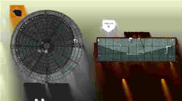
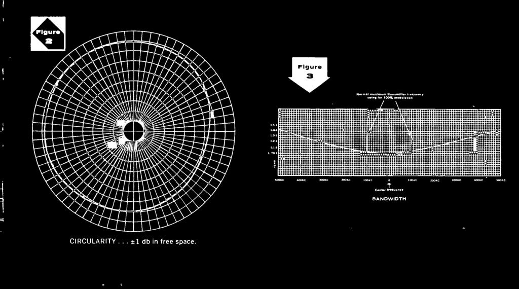
5 MSC /41014C AMC 200KC ISM 100/. 4. CIMIet Imo..., BANDWIDTH %O. MAC SAM NM CIRCULARITY... ±1 db in free space.


6 NEWEST FIELD- PROVEN DEVELOPMENT IN FM RADIATING ELEMENTS.
P300/P350 Series. Vertically Polarized FM Antenna. Features. Characteristics
 Vertically Polarized FM Features Low VSWR, superior VSWR band width, minimal weather related VSWR problems Fully pressurized, internal feed, welded feed connections, series fed radiating elements High
Welcome to AntennaSelect Volume 20 June New FMM - mid power FM antennas
 Welcome to AntennaSelect Volume 20 June 2015 Welcome to Volume 20 of our newsletter, AntennaSelect TM. Each month we will be giving you an under the radome look at antenna and RF technology. If there are
ABOUT JAMPRO CONTINUING THE TRADITION
 JAMPRO ANTENNAS, INC. Your Partner for DTV-DVB-T & HD Radio Solutions- the oldest, most experienced broadcast antenna company in North America with over 50 years of experience providing Complete Turnkey
ROTOTILLER. Circularly Polarized FM Antenna. Benefits. Characteristics
 Benefits Low VSWR, superior VSWR band width, and minimal weather related VSWR problems Fully pressurized, internal feed and welded feed connections High input power capacity Modular construction facilitates
Type 2701 and 2702 Series GRANGER Horizontally Polarized, Log-Periodic HF Antennas
 Type 2701 and 2702 Series GRANGER Horizontally Polarized, Log-Periodic HF Antennas 2-30 MHz Frequency Range Up to kw Average, kw Peak Power Rating Horizontal Polarization 2.0:1 Maximum VSWR Short-to-Medium-Range
First DTV Antenna on the Hancock Building Chicago, USA
 FRONT COVER (Front Cover Photo) UHF Top-mount Combined Antenna System Highest Power Antenna in Asia (Jakarta, Indonesia) First DTV Antenna on the Hancock Building Chicago, USA JAMPRO ANTENNAS, INC. Your
High Powered History
 The Broadcasters Desktop Resource www.thebdr.net edited by Barry Mishkind the Eclectic Engineer High Powered History Building the Sears Tower Site Part 3 By Warren Shulz [July 2014] History can be a slippery
360 inches (915 cm) 240 inches (610 cm) 120 inches (305 cm) 240 inches is the recommended pole length, 360 inches is the recommended free space area
 240 inches (610 cm) 120 inches (305 cm) 240 inches is the recommended pole length, 360 inches is the recommended free space area") FML C/P FM Antenna Right hand C/P Polarization Low wind load area Up to 1 kw Rating per bay Omni-directional Up to 8 kw input per array with power divider options The FML series of antennas are narrow
FML C/P FM Antenna Right hand C/P Polarization Low wind load area Up to 1 kw Rating per bay Omni-directional Up to 8 kw input per array with power divider options The FML series of antennas are narrow
Band I (Low VHF) TV Panel Arrays MHz. 606L Series BROADCAST ANTENNA SYSTEMS
 TV Panel Arrays MHz. 606L Series BROADCAST ANTENNA SYSTEMS") Band I (Low VHF) TV Panel Arrays 44-88 MHz L Series The L series of panels are low wind load antennas suitable to provide a customized coverage for any single TV channel in Band I. Low wind load Pressurizable
Band I (Low VHF) TV Panel Arrays 44-88 MHz L Series The L series of panels are low wind load antennas suitable to provide a customized coverage for any single TV channel in Band I. Low wind load Pressurizable
Chapter 6 Antenna Basics. Dipoles, Ground-planes, and Wires Directional Antennas Feed Lines
 Chapter 6 Antenna Basics Dipoles, Ground-planes, and Wires Directional Antennas Feed Lines Some General Rules Bigger is better. (Most of the time) Higher is better. (Most of the time) Lower SWR is better.
AL PLUS Series. Low and Medium Power UHF Television Antenna. Low and Medium Power UHF Antenna Systems. Features. Characteristics
 AL PLUS Series Features Fast delivery Light weight, low windload Quick, low-cost installation Four azimuth patterns available Up to 10 kw DTV (23 kw analog) input power rating 8- and 12-bay models Multichannel
Low Power FM Antenna Systems
 Low Power FM Antenna Systems J3YF J3YF 3 ELEMENT FM YAGI ANTENNA JAMPRO Yagi 3 Element Antenna Hot Dip Galvanized Steel Directional Radiation Pattern Suitable for Medium and High Power FM Stacked Array
UHF Band IV-V TV Antennas I230E Series -4 dipoles Panels-
 Broadcast Antennas TV UHF UHF Band IV-V TV Antennas I230E Series -4 dipoles Panels- Electrical characteristics I230 EH I230 EV I230 EC Frequency range (MHz) 470-860 Input impedance (ohm) 50 Horizontal
780-8 Series Constant Impedance FM Combiners
 Features Cylindrical construction provides better mechanical and electrical stability than square or rectangular cavities Factory tuned to customer s specified channel, yet can be easily field converted
Welcome to AntennaSelect Volume 28 October 2016
 Welcome to AntennaSelect Volume 28 October 216 Welcome to Volume 28 of our newsletter, AntennaSelect TM. Every two months we will be giving you an under the radome look at antenna and RF Technology. If
A Technical Report: Jampro s Dual Input Interleaved HD FM antenna:
 A Technical Report: Jampro s Dual Input Interleaved HD FM antenna: This JMPC-2 + JMPC-2-HD is shown installed on a 24 triangle tower. Many other configurations are available to meet your HD Radio Needs.
Welcome to AntennaSelect Volume 40 October Update on Antenna Delivery Times:
 Welcome to AntennaSelect Volume 40 October 2018 Welcome to Volume 40 of our newsletter, AntennaSelect TM. Every two months we will be giving you an under the radome look at antenna and RF Technology. If
New Antenna Designs for DTV Implementation
 New Antenna Designs for DTV Implementation JOHN L. SCHADLER and KERRY COZAD Dielectric Communications Raymond, Maine ABSTRACT WIDE BAND CAVITY ANTENNA (TFU-WB) Over the past few years the implementation
ERI FM Band Pass Filters
 ERI 780-3 FM Band Pass Filters Features Cylindrical construction provides better mechanical and electrical stability than square or rectangular cavities Factory tuned to customer s specified channel, yet
INSTRUCTION MANUAL. Specifications Mechanical. 1 5/8 to 2 1/16 O.D. (41mm to 52mm)
") 308 Industrial Park Road Starkville, MS 39759 USA Ph: (662) 323-9538 FAX: (662) 323- General Description Model VB-25FM 2-Meter 5 Elements Beam INSTRUCTION MANUAL This antenna is a 5-element, 2-meter beam
308 Industrial Park Road Starkville, MS 39759 USA Ph: (662) 323-9538 FAX: (662) 323- General Description Model VB-25FM 2-Meter 5 Elements Beam INSTRUCTION MANUAL This antenna is a 5-element, 2-meter beam
Array Solutions OCF Series Dipoles
 OCF Series Dipoles Fig 1 Thank you and congratulations on your purchase of the, Off- Center Fed HF Dipole Antenna System. This antenna was built with the same quality workmanship and attention to detail
db Systems Model 5100A-HS-ICE DME Antenna
 Installation Manual db Systems Model 5100A-HS-ICE DME Antenna HEATED RADOME HIGH PERFORMANCE DME ANTENNA MANUFACTURER db SYSTEMS, INC. 2005 SOUTH TURF SOD ROAD HURRICANE, UT 84737 DATE OF ORIGINAL ISSUE:
Broadcast Antenna & Service Guide
 Telecommunications Broadcast Antenna & Service Guide Multiple Solutions Various Patterns and Gain Coaxial, Dipole and Patch Designs www.alivetele.com 2 Alive Telecom - Variety of Antenna System Solutions
Antennas. You re heard, loud and clear.
 Antennas You re heard, loud and clear. PIM-RATED ANTENNAS COL Series VHF and UHF Meander Collinear The Meander Collinear Antennas, available in both the VHF, UHF and 700/800 MHz bands, have been specifically
A Technical Report: Jampro s Dual Input Shared Aperture HD FM antenna:
 A Technical Report: Jampro s Dual Input Shared Aperture HD FM antenna: This JMPC-2 + JMPC-2-HD is shown installed on a 24 triangle tower. Many other configurations are available to meet your HD Radio Needs.
Model VB-23FM 2-Meter 3-Element Beam
 308 Industrial Park Road Starkville, MS 39759 USA Ph: (662) 323-9538 FAX: (662) Model VB-23FM 2-Meter 3-Element Beam [ INSTRUCTION MANUAL Figure 1 Overall View and Boom Detail GENERAL DESCRIPTION This
700 and 800 MHz Band Slot Antennas
 Low Group Delay, Wide Bandwidth UHF Slot Antennas Omni-directional and Directional Patterns Available Low RFR Models Available Top or Side Mount Models Horizontal, Elliptical, or Circular Polarization
I TECH S.r.l. Via Pompei n. 35, gallarate (VA) - ITALY VAT / CF PEC
 - ITALY VAT / CF PEC") I TECH S.r.l. Via Pompei n. 35, 21013 gallarate (VA) - ITALY VAT / CF 03479116123 Email: broadcasting@irte.it, PEC Itechsrl@legalmail.it - Tel +39 0331 797286 Broadcast FM NFV71000 FM Dipole FM Band Product
I TECH S.r.l. Via Pompei n. 35, 21013 gallarate (VA) - ITALY VAT / CF 03479116123 Email: broadcasting@irte.it, PEC Itechsrl@legalmail.it - Tel +39 0331 797286 Broadcast FM NFV71000 FM Dipole FM Band Product
MFJ-941E Versa Tuner II GENERAL INFORMATION:
 GENERAL INFORMATION: MFJ VERSA TUNER II The MFJ-941E is designed to match virtually any transmitter to any antenna, including dipoles, inverted-vees, verticals, mobile whips, beams, random wires, and others
MHz. ANT150D, D3, D6-9 DIPOLE AND DIPOLE ARRAY 1 TO 9 dbd
 138-174 MHz ANTD, D3, D6-9 DIPOLE AND DIPOLE ARRAY 1 TO 9 dbd The Telewave ANTD series consists of single, dual, and 4-element di pole array antennas with a precision phasing harness for optimum per formance.
Repack Space Squeeze How Long is That FM Antenna? Multi-Bay Antennas and AM Translators
 Welcome to AntennaSelect Volume 27 August 2016 Welcome to Volume 27 of our newsletter, AntennaSelect TM. Every two months we will be giving you an under the radome look at antenna and RF Technology. If
I TECH S.r.l. Via Pompei n. 35, gallarate (VA) - ITALY VAT / CF PEC
 - ITALY VAT / CF PEC") I TECH S.r.l. Via Pompei n. 35, 21013 gallarate (VA) - ITALY VAT / CF 03479116123 Email: broadcasting@irte.it, PEC Itechsrl@legalmail.it - Tel +39 0331 797286 Broadcast FM NFV71000 FM Dipole FM Band Product
I TECH S.r.l. Via Pompei n. 35, 21013 gallarate (VA) - ITALY VAT / CF 03479116123 Email: broadcasting@irte.it, PEC Itechsrl@legalmail.it - Tel +39 0331 797286 Broadcast FM NFV71000 FM Dipole FM Band Product
The DBJ-1: A VHF-UHF Dual-Band J-Pole
 By Edison Fong, WB6IQN The DBJ-1: A VHF-UHF Dual-Band J-Pole Searching for an inexpensive, high-performance dual-band base antenna for VHF and UHF? Build a simple antenna that uses a single feed line for
Welcome to AntennaSelect Volume 34 October UHF and VHF Stacked Antenna Pylons
 Welcome to AntennaSelect Volume 34 October 2017 Welcome to Volume 34 of our newsletter, AntennaSelect TM. Every two months we will be giving you an under the radome look at antenna and RF Technology. If
Telecommunication Wiring Questions
 Telecommunication Wiring Questions 1. is the process of modifying a carrier frequency in rhythm to the audio frequency. A, Modulation B. Amplitude C. Change of phase D. Interference 2. is the property
FAST MAST ANTENNA SYSTEM
 FAST MAST ANTENNA SYSTEM FAST DEPLOYMENT RECEIVER HITCH 25 ANTENNA TOWER DEPLOY YOUR ANTENNA SYSTEM IN LESS THAN 5 MINUTES THE EXTENDS FROM 7.5 FT UP TO 25 FT OR ANY POINT INBETWEEN. CONSTRUCTED FROM HEAVY
I TECH S.r.l. Via Pompei n. 35, gallarate (VA) - ITALY VAT / CF PEC
 - ITALY VAT / CF PEC") I TECH S.r.l. Via Pompei n. 35, 21013 gallarate (VA) - ITALY VAT / CF 03479116123 Email: broadcasting@irte.it, PEC Itechsrl@legalmail.it - Tel +39 0331 797286 Broadcast FM NFV71000 FM Dipole FM Band Product
I TECH S.r.l. Via Pompei n. 35, 21013 gallarate (VA) - ITALY VAT / CF 03479116123 Email: broadcasting@irte.it, PEC Itechsrl@legalmail.it - Tel +39 0331 797286 Broadcast FM NFV71000 FM Dipole FM Band Product
Laird Technologies Base Station Antennas
 Omnidirectional Laird Technologies Base Station Antennas Laird Technologies offers an extensive array of base station and in-building wireless antennas. Responding to the ever-increasing variety of frequencies
Testing and Results of a New, Efficient Low-Profile AM Medium Frequency Antenna System
 Testing and Results of a New, Efficient Low-Profile AM Medium Frequency Antenna System James K. Breakall, Ph.D. Pennsylvania State University University Park, PA Michael W. Jacobs Star-H Corporation State
ARNSW Balun Day. Balun construction
 ARNSW Balun Day Balun construction Typical Baluns All built from locally available components. Balun uses Most baluns are used to match the 50Ω output of a transceiver to an antenna. A centre fed dipole
General Product Brochure
 General Product Brochure SteppIR Antennas 2112 116th Ave NE #1-5 Bellevue, WA 98004 Tel: 425.453.1910 sales@steppir.com www.steppir.com SteppIR - Why Compromise? The SteppIR antenna was conceived to solve
Standard Rigid Line STD775 Series
 Specifications Product Series STD775 Size 7-3/16 Impedance 75 ± 0.5-ohm Maximum Channel 69 Velocity, % 99.8 Peak Rating, 1400 Net Weight, lb/ft (kg/m) 8.21 Outer Conductor Outside Diameter, in (mm) 7.15
MQ-24SR Miniature Four band Hybrid Quad Antenna
 MQ-24SR Miniature Four band Hybrid Quad Antenna Most antennas are large heavy structures requiring heavy duty structures, rotors and lots of extra muscle during installation and lots of extra dollars before
Development of a noval Switched Beam Antenna for Communications
 Master Thesis Presentation Development of a noval Switched Beam Antenna for Communications By Ashraf Abuelhaija Supervised by Prof. Dr.-Ing. Klaus Solbach Institute of Microwave and RF Technology Department
By Paul Melbourne G8GML and Ian Waters G3KKD.
 23cm Panel Antennas By Paul Melbourne G8GML and Ian Waters G3KKD. This article describes a range of panel antennas developed by G8GML. It is a sequel to an article by John Stockley, G8MMY, published in
Mast Mount Omnidirectional (MMO) Antennas
 Antennas") Mast Mount Omnidirectional Antennas Mast Mount Omnidirectional (MMO) Antennas The MMO series base antenna provides outstanding coverage in a rugged U.V. stable, plastic radome with an aluminum base that
Mast Mount Omnidirectional Antennas Mast Mount Omnidirectional (MMO) Antennas The MMO series base antenna provides outstanding coverage in a rugged U.V. stable, plastic radome with an aluminum base that
M2 Antenna Systems, Inc. Model No: 2M HO LOOP
 M2 Antenna Systems, Inc. Model No: 2M HO LOOP SPECIFICATIONS: Model... 2M HO LOOP Frequency Range... 144 To 144.5 MHz Gain, Typical @ 10 ft.... 4 dbd @ 10 deg. Gain, 2 STK @ 82 & 132... 8 dbd @ 9 deg.
The J-Pole Antenna. Gary Wescom
 The J-Pole Antenna Gary Wescom - 2018 Much has been written about the J-Pole antenna. A simple Google search will net days worth of reading material on the subject. That would tend to indicate this paper
5/1.0 kw AM Transmitter
 5/1.0 kw AM Transmitter Collins' 820E /F -1 series of broadcast transmitters is one of the most extensively transistorized series of transmitters available in the 5 -kw to 10 -kw power range. The series
AS-3226C/URC VHF ANTENNA
 TECHNICAL MANUAL OPERATION AND INSTALLATION INSTRUCTIONS AS-3226C/URC VHF ANTENNA REVISION SHEET Revision Description Date - - Original Issue - November 13, 2007 Errors in this publication can be reported
Newcomers And Elmers Net: Wire Antennas Robert AK3Q
 Newcomers And Elmers Net: Wire Antennas 02-07-16 Robert AK3Q Wire antennas represent one of the greatest values in the radio hobby world. For less than the cost of a good meal out on the town you can buy
Model BiConiLog Antenna. User Manual
 Model 3149 BiConiLog Antenna User Manual ETS-Lindgren Inc. reserves the right to make changes to any products herein to improve functioning or design. Although the information in this document has been
Introduction. Understanding Power Ratings. Peak Reading SWR/Wattmeter
 Introduction The MFJ-962D is a "T" network roller inductor tuner with built-in antenna switching, RF power and SWR metering and a 1:1 balun. The largest amplifiers that can safely be used include the Heathkit
Least understood topics by most HAMs RF Safety Ground Antennas Matching & Feed Lines
 Least understood topics by most HAMs RF Safety Ground Antennas Matching & Feed Lines Remember this question from the General License Exam? G0A03 (D) How can you determine that your station complies with
KS CONICAL ANTENNA AND WAVEGUIDE SYSTEM DESCRIPTION
 BEU SYSTEM PRACTICES AT&TCa Standard SECTION 402-422-100 Issue 1, October 1979 MICROWAVE ANTENNAS KS-2 1972 CONICAL ANTENNA AND WAVEGUIDE SYSTEM DESCRIPTION CONTENTS I. GENERAL...........1 PAGE 2. INTRODUCTION.........
The Principle V(SWR) The Result. Mirror, Mirror, Darkly, Darkly
 The Result. Mirror, Mirror, Darkly, Darkly") The Principle V(SWR) The Result Mirror, Mirror, Darkly, Darkly 1 Question time!! What do you think VSWR (SWR) mean to you? What does one mean by a transmission line? Coaxial line Waveguide Water pipe Tunnel
The Principle V(SWR) The Result Mirror, Mirror, Darkly, Darkly 1 Question time!! What do you think VSWR (SWR) mean to you? What does one mean by a transmission line? Coaxial line Waveguide Water pipe Tunnel
SB-400 HF Antennas SB-400
 SB-400 HF Antennas SB-400 The SB-400 Series of antennas are man-portable and rapid-deployable for HF communications. The HF ANTENNA communication mode is for paths from 10 to 400 km. This communication
4 Antennas as an essential part of any radio station
 4 Antennas as an essential part of any radio station 4.1 Choosing an antenna Communicators quickly learn two antenna truths: Any antenna is better than no antenna. Time, effort and money invested in the
FM Wide Band Panel Dipole Antenna
 IEEE TRANSACTIONS ON BROADCASTING, VOL. 48, NO. 4, DECEMBER 2002 317 FM Wide Band Panel Dipole Antenna Valentín Trainotti, Senior Member, IEEE and Norberto Dalmas Di Giovanni, Member, IEEE Abstract It
Array Solutions Four Square Array Manual and User s Guide
 Array Solutions Four Square Array Manual and User s Guide Array Solutions Four Square Array Pattern Steering System Congratulations! You have selected one of the finest phased array steering systems made.
A short, off-center fed dipole for 40 m and 20 m by Daniel Marks, KW4TI
 A short, off-center fed dipole for 40 m and 20 m by Daniel Marks, KW4TI Version 2017-Nov-7 Abstract: This antenna is a 20 to 25 foot long (6.0 m to 7.6 m) off-center fed dipole antenna for the 20 m and
Input Return Loss, db > 26 Narrowband to Narrowband Isolation, db > 30
 Band III (VHF) TV Commutating Line Combiner 174-222 MHz CC VHF Series This style of circuit provides a relatively low cost combiner which is ideal, provided the frequency spacing is not too close. Compact,
Technician Licensing Class. Antennas
 Technician Licensing Class Antennas Antennas A simple dipole mounted so the conductor is parallel to the Earth's surface is a horizontally polarized antenna. T9A3 Polarization is referenced to the Earth
Installation Instructions Hustler Collinear Two Meter Fixed Station Antenna Master Gainer Model G6-144B
 Installation Instructions Hustler Collinear Two Meter Fixed Station Antenna Master Gainer Model Warning INSTALLATION OF THIS PRODUCT NEAR POWER LINES IS DANGEROUS. FOR YOUR SAFETY, FOLLOW THE INSTALLATION
Log Periodic Dipole Array Antenna
 Model 3148B Log Periodic Dipole Array Antenna User Manual ETS-Lindgren L.P. reserves the right to make changes to any product described herein in order to improve function, design, or for any other reason.
Improved Ionospheric Propagation With Polarization Diversity, Using A Dual Feedpoint Cubical Quad Loop
 Improved Ionospheric Propagation With Polarization Diversity, Using A Dual Feedpoint Cubical Quad Loop by George Pritchard - AB2KC ab2kc@optonline.net Introduction This Quad antenna project covers a practical
Alpha Delta Communications, Inc. Model DX-OCF Off-Center-Fed 7 Band Antenna
 Alpha Delta Communications, Inc. Model DX-OCF Off-Center-Fed 7 Band Antenna 75/80, 40, 20, 17, 12, 10, and 6 meters (50.0-51.0 MHz) NO TUNER REQUIRED! Installation Instructions One leg is 45 ft., the other
SD230T. Frequency Range, MHz Average, 0.6 PEP,1 Average, 3 PEP. <2.0:1 for 3 to 20MHz, <2.5:1 for 2 to 30MHz
 Tactical Semidelta Antennas 2-30MHz SD-T Series The RFS Model SD230T antenna is a transportable, broadband, lightweight, traveling wave antenna for short to medium range ionospheric communications. For
Antenna Trainer EAN. Technical Teaching Equipment INTRODUCTION
 Antenna Trainer EAN Technical Teaching Equipment Products Products range Units 3.-Communications INTRODUCTION Antennas are the main element of aerial communications. They are the transition between a transmission
DL Series UHF Top Mount Slot Antennas
 Low Group Delay True Center Fed Design Wide Range of Standard And Custom Azimuth Patterns Available In 8 To 32 Bay Models, In 2 Bay Increments to 65 kw Input Power Ratings Horizontal, Elliptical and Circular
GATES WITH BUT 3 PERCENT FREQUENCY SEPARATION DIPLEXING AM TRANSMITTERS GATES ENGINEERING REPORT HARRIS I NTE RTYPE A DIVISION OF HARRIS-INTERTYPE
 GATES ENGINEERING REPORT DIPLEXING AM TRANSMITTERS WITH BUT 3 PERCENT FREQUENCY SEPARATION HARRIS I NTE RTYPE CORPORATION GATES A DIVISION OF HARRIS-INTERTYPE Communications and Information Handling Equipment
The Spectrum Repack: Is there a move to VHF in your future? Bill Ammons Broadcasters Clinic 2016
 The Spectrum Repack: Is there a move to VHF in your future? Bill Ammons Broadcasters Clinic 2016 Maybe a move to VHF in your future? A quick look back at the analog era model, what worked, what did not
A Transmatch for Balanced or Unbalanced Lines
 A Transmatch for Balanced or Unbalanced Lines Most modern transmitters are designed to operate into loads of approximately 50 Ω. Solid-state transmitters produce progressively lower output power as the
MFJ-969 Versa Tuner II Instruction Manual
 MFJ-969 Versa Tuner II Instruction Manual General Information The MFJ-969 is a 300 watt RF output power antenna tuner that will match any transmitter or transceiver to virtually any antenna. Peak or average
Intermediate Course (5) Antennas and Feeders
 Antennas and Feeders") Intermediate Course (5) Antennas and Feeders 1 System Transmitter 50 Ohms Output Standing Wave Ratio Meter Antenna Matching Unit Feeder Antenna Receiver 2 Feeders Feeder types: Coaxial, Twin Conductors
Intermediate Course (5) Antennas and Feeders 1 System Transmitter 50 Ohms Output Standing Wave Ratio Meter Antenna Matching Unit Feeder Antenna Receiver 2 Feeders Feeder types: Coaxial, Twin Conductors
SPECIAL SPECIFICATION 6574 Low Power Wireless Modem
 2004 Specifications CSJ 1068-04-126, etc. SPECIAL SPECIFICATION 6574 Low Power Wireless Modem 1. Description. This work shall consist of furnishing and supplying a Low Power Wireless Modem at the locations
I recently came across a No-Counterpoise antenna described by designed by Peter Millis M3KXZ and based on an original design by K9ESE.
 M3KXZ 'no counterpoise' antenna I recently came across a No-Counterpoise antenna described by designed by Peter Millis M3KXZ and based on an original design by K9ESE. Details of the antenna can be found
Welcome to AntennaSelect Volume 10 May Optimizing VHF (Band III) Batwing antennas - Part 2
 Batwing antennas - Part 2") Welcome to AntennaSelect Volume 10 May 2014 Welcome to Volume 10 of our newsletter, AntennaSelect TM. Each month we will be giving you an under the radome look at antenna and RF technology. If there are
Welcome to AntennaSelect Volume 10 May 2014 Welcome to Volume 10 of our newsletter, AntennaSelect TM. Each month we will be giving you an under the radome look at antenna and RF technology. If there are
KS-5708 LIST 1 PERFORATED PARABOLIC ANTENNA DESCRIPTION
 BELL SYSTEM PRACTICES Plant Series SECTION 402-431-l W Issue 1, July, 1947 AT8TC0 Standard MICROWAVE ANTENNAS KS-5708 LIST 1 PERFORATED PARABOLIC ANTENNA DESCRIPTION CONTENTS PAGE 2 CIRCUIT DESCRIPTION
Rigid Line Components and Accessories
 Rigid Line Components and ccessories Rigid Coaxial Line System Components and Installation ccessories enefits Superior engineering for excellent performance Superior materials for high durability merican
Loop and Slot Antennas
 Loop and Slot Antennas Prof. Girish Kumar Electrical Engineering Department, IIT Bombay gkumar@ee.iitb.ac.in (022) 2576 7436 Loop Antenna Loop antennas can have circular, rectangular, triangular or any
MFJ-949E. tuner antenowy skrzynka antenowa. Instrukcja obsługi. importer:
 Instrukcja obsługi MFJ-949E tuner antenowy skrzynka antenowa importer: PRO-FIT Centrum Radiokomunikacji InRadio ul. Puszkina 80 92-516 Łódź tel: 42 649 28 28 e-mail: biuro@inradio.pl www.inradio.pl MFJ-949E
RADIO AND TELEVISION TOWER & EQUIPMENT PROPERTY DAMAGE APPLICATION
 Hull & Company Dallas P: (972) 789-1962 F: (972) 789-1967 Houston P: (281) 759-4855 F: (281) 759-7245 hullandco-texas.com RADIO AND TELEVISION TOWER & EQUIPMENT PROPERTY DAMAGE APPLICATION The following
3000 Series Granger Broadband HF Multi-Mode SPIRA-CONE Antennas
 3000 Series Granger Broadband HF Multi-Mode SPIRA-CONE Antennas 2 to 30 MHz Frequency Range, Dependent Upon Up to KW Average, 40 KW Peak Power Rating Horizontal-Elliptical to Reduce Fading Log-Periodic
LPFM Antenna Applications and Engineering Guide
 LPFM Antenna Applications and Engineering Guide We have received a lot of questions from new LPFM station operators about how to get the best coverage for their station. We have answered some of these
Transmission Line Support Systems
 Antenna Support Bracket for transmission line The Antenna Support Bracket angle mounts directly to a 4-1/2" (114 mm) OD antenna pipe mount or tower leg. This is ideal for supporting transmission line runs
CHAPTER 8 ANTENNAS 1
 CHAPTER 8 ANTENNAS 1 2 Antennas A good antenna works A bad antenna is a waste of time & money Antenna systems can be very inexpensive and simple They can also be very expensive 3 Antenna Considerations
Equipment Rack Grounding. Technical Note
 Equipment Rack Grounding Technical Note Equipment Rack Grounding Surge Protection Solutions for PTC 1 Equipment Rack Grounding Equipment racks and cabinets can provide an unwanted path for lightning surge
K1FO 12 ELEMENT 144/147 MHz YAGI
 K1FO 12 ELEMENT 144/147 MHz YAGI WARNING: INSTALLATION OF THIS PRODUCT NEAR POWER LINES IS DANGEROUS. FOR YOUR SAFETY FOLLOW THE INSTALLATION DIRECTIONS. Ariane Arrays, Inc. Copyright 2006 201 Hopedale
SpecifIcations DCF 500 DCF 2000 DCF 5000 TCF 3000
 FM Double & Triple Cavity Filters DCF 500 DCF 2000 DCF 5000 TCF 3000 These high quality Cavity Filters are one-quarter wavelength coaxial cavities designed for the 87,5 108 MHz band. They are band pass
BCA. Combiners and Filters for FM Broadcast and TV Systems
 BCA Combiners and Filters for FM Broadcast and TV Systems Photo on title page: FM Multipattern Combiner, 3x 10 kw Catalogue Issue 03/2007 All data published in previous catalog issues hereby becomes invalid.
AD511-2 Active Iridium Antenna User Manual. 1 AD511-2 Active Iridium Antenna User Manual October FEBRUARY 2018 V2.0
 AD511-2 Active Iridium Antenna User Manual 1 AD511-2 Active Iridium Antenna User Manual October 2017 1.0 FEBRUARY 2018 V2.0 TABLE OF CONTENTS 1. FCC APPROVAL... 3 1.1. FCC 15.19 (A) (3)... 3 1.2. FCC 15.105
LMR LMR Ohm Flexible Low Loss Coaxial Cable TIMES MICROWAVE SYSTEMS
 LMR-200-75 LMR -200-75 Ohm Flexible Low Loss Coaxial Cable Ideal for Satellite Applications Video Applications-CCTV, CATV, baseband or broadband In-Building Feeder Runs Any 75 ohm Wireless Application
MFJ-945E. tuner antenowy skrzynka antenowa. Instrukcja obsługi. importer:
 Instrukcja obsługi MFJ-945E tuner antenowy skrzynka antenowa importer: PRO-FIT Centrum Radiokomunikacji InRadio ul. Puszkina 80 92-516 Łódź tel: 42 649 28 28 e-mail: biuro@inradio.pl www.inradio.pl MFJ-945E
Circularly Polarized FM Broadcast Antenna
 Circularly Polarized FM Broadcast Antenna Versa2une (SLV) 6 to 12-bay, full-wave-spaced Instruction Manual Installation, Operation, & Maintenance Congratulations! Thank you for purchasing one of the finest
SMA - 50 Ohm Connectors
 For Flexible Cable Straight Crimp Type Plug - Captivated Contact CABLE TYPE RG-178/U, 196 1.20 +.025 f (GHz) 0-12.4 GHz 142-0402-001 142-0402-006 RG-161/U, 174,188, 316 RG-188 DS, RG-316 DS RG-58/U, 141,
Installation Instructions Hustler 6-BTV Trap Vertical
 Installation Instructions Hustler 6-BTV Trap Vertical ASSEMBLY 1. Check the package contents against the parts list on page 2. 2. WARNING. Installation of this product near power lines is dangerous. For
 New Products Frequency and Time The new Pride TF -1000 offers a combined frequency counter and selectable 12- or 24 -hour digital clock. Utilizing FET switching techniques, the TF -1000 provides an accurate
ASSEMBLY AND INSTALLATION INSTRUCTIONS R , 12, 15, 17, 20, 30, 40 Meters (5/99) COMMUNICATIONS ANTENNAS
 COMMUNICATIONS ANTENNAS") ASSEMBLY AND INSTALLATION INSTRUCTIONS R7000 10, 12, 15, 17, 20, 30, 40 Meters COMMUNICATIONS ANTENNAS 951465 (5/99) WARNING THIS ANTENNA IS AN ELECTRICAL CONDUCTOR. CONTACT WITH POWER LINES CAN RESULT
ASSEMBLY AND INSTALLATION INSTRUCTIONS R7000 10, 12, 15, 17, 20, 30, 40 Meters COMMUNICATIONS ANTENNAS 951465 (5/99) WARNING THIS ANTENNA IS AN ELECTRICAL CONDUCTOR. CONTACT WITH POWER LINES CAN RESULT
Optimizing Your Stations Performance
 Optimizing Your Stations Performance A few hints / techniques, recommendations for getting the most RF out to the Antenna from your HF, VHF / UHF station. Tonights Presenters: Doug Theriault NO1D John