Antennas Orbits Modulation Noise Link Budgets U N I V E R S I T Y O F. Spacecraft Communications MARYLAND. Principles of Space Systems Design
|
|
|
- Roberta Gibson
- 5 years ago
- Views:
Transcription
1 Antennas Orbits Modulation Noise Link Budgets
2 The Problem Pointing Loss Polarization Loss Atmospheric Loss, Rain Loss Space Loss Pointing Loss Transmitter Antenna SPACE CHANNEL Receiver Power Amplifier Galactic, Star, Terrestrial Noise Antenna Transmitter Modulator Receiver Noise Receiver Encoder Command & Data Handling (C&DH) Information Implementation Loss Demodulator Decoder Compression Information Data Decompression Satellite transmitter-to-receiver link with typical loss and noise sources
3 Antennas Receive & transmit RF (radio frequency) energy Size/type selected directly related to frequency/required gain Omni Antenna (idealized) Gain Pattern Directional (Hi-Gain) Antenna dbi Isotropic antenna Omni Antenna (typical) phi = 0 degrees Theta Cut plot1 mtheta 170 plot2 mtheta Three_dB db Beamwidth f = 2209 serial = MHz efficiency= Test_date = "May 22, 2002" 240 "Dryden AK490 Final" $ mtheta # step! # " ' % ( & 180 ) , 300 ( 360mthetastep! * # ) # " 180, i_3db 1000 # 2 # " db_per_div= 2 RHCP_max= Plot_max= db 320 dbic db max On-axis gain max OAgainmax= test_range = "Anechoic C Gain is relative to isotropic with units of dbi Side Lobes Boresight Peak Gain = X dbi
4 Orbit Considerations UNIVERSITY OF

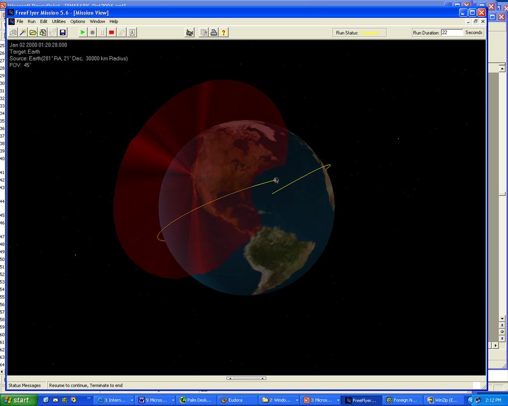
5 Ground Station Coverage
6 Ground Station Coverage Florida ground station with spacecraft altitudes 400, 800, and 1200 km 400 km 800 km 1200 km Merritt Island
7 Ground Station Coverage Ground station elevation angles of 0, 10, and 20 degrees
8 Ground Station Coverage Effects of terrain and antenna limitations Another antenna Building Antenna limits
9 Ground Station Coverage Hawaii (HAW3), Alaska (AGIS), Wallops Island (WPSA), Svalbard (SGIS), McMurdo (MCMS) AGIS Svalbard HAW3 WPSA MCMS
10 Frequency Bands S-Band 2-3 GHz Space operation, Earth exploration, Space research X-Band 7-8 GHz Earth exploration, Space research Ku-Band GHz Space research Loss from rain Ka-Band GHz Inter-satellite, Earth exploration Radio TV VHF S-Band C-Band X-Band Ku-Band Ka-Band W-Band Lasers
11 Types of Modulation Amplitude Modulation s(t) = A [1 + m(t)] cos(2πf c t) Easy to implement Poor noise performance Frequency Modulation x(t) = A cos[2π 0->t (f c + f m(τ))dτ] Requires frequency lock loop Polarization Modulation s(t) = A cos[2πf c t + βm(t)] Requires phase lock loop Most digital modulation techniques involve PM


12 Polarization Orientation of electric field vector Shape traced by the end of the vector at a fixed location, as observed along the direction of propagation Some confusion over left hand/right hand conventions Linear Polarization Vertical Linear Polarization Horizontal Circular Polarization Left hand C ircular Polarization Right hand
13 Digital Modulation Techniques On-Off Keying (OOK) Frequency Shift Keying (FSK) Bi-Phase Shift Keying (BPSK) Quadrature Phase Shift Keying (QPSK) BPSK QPSK
14 Noise Any signal that isn t part of the information sent Signal noise Amplitude noise error in the magnitude of a signal Phase noise error in the frequency / phase modulation System Noise Component passive noise Component active noise (amplifiers, mixers, etc ) Environmental Noise Atmospheric noise Galactic noise Precipitation

15 Signal Noise Amplitude Noise Phase Noise
16 System Noise All real components generate thermal noise due to the random motion of atoms Passive devices thermal noise is directly related to the temperature of the device, its bandwidth, and the frequency of operation Noise is generated by thermal vibration of bound charges A moving charge generates an electromagnetic signal Passive components include Resistive loads (power loads) Cables & other such things (like waveguides)
17 Environmental Noise Rain loss, particularly in the Ku band Snow is not a problem Lightning Stars, galaxies, planets Human interference
18 Noise Temperature Noise temperature provides a way of determining how much thermal noise is generated in the receiving system The physical noise temperature of a device, T n, results in a noise power of P n = KT n B K = Boltzmann s constant = 1.38 x J/K; K in dbw = dbw/k T n = Noise temperature of source in Kelvins B = Bandwidth of power measurement device in hertz Satellite communications systems work with weak signals, so reduce the noise in the receiver as far as possible Generally the receiver bandwidth is just large enough to pass the signal Liquid helium can hold the physical temperature down
19 S/N and NF Signal to Noise Ratio Most common description of the quantity of noise in a transmission Noise Figure S/N of input divided by S/N of output for a given device (or devices) in a communications system Related to the noise temperature of a device: T d = T 0 (NF - 1) T 0 = reference temperature, usually 290 K
20 System Noise Temperature Example 1: Gain = 0 dbi 3 db T sky = 50 LNA Dow nconv erter IF AMP RECEIVER Loss = L 1!= L 1!= 3 db/ NF LNA = 2 db = G LNA = 35 db = W = 0.5 NF DC = 10 db = 10 G DC = 30 db = 1000 W NF IF = 10 db = 10 G IF = 30 db = 1000 W NF R = 10 db = 10 G R = 30 db = 1000 W T Reference Point Reference Point = 0 db System Noise Temperature T s K T o is reference temperature of each device = 290 K (assumed) ( 1"!) T ( NF " 1) T ( NF " 1) T ( NF " ) o LNA o PC o IF 1 To Ts # Tsky !!! G! G G LNA LNA DC T s = *0.585*290 + (2*10*290 /3162.3) * (1 + 1/1, /1,000,000) T s = K = db
21 System Noise Temperature Example 2: Gain = 0 dbi 3 db T sky = 50 LNA Dow nconv erter IF AMP RECEIVER Loss = L 1!= L 1 = != 3 db/ 10 NF LNA = 2 db = G LNA = 35 db = W NF DC = 10 db = 10 G DC = 30 db = 1000 W NF IF = 10 db = 10 G IF = 30 db = 1000 W NF R = 10 db = 10 G R = 30 db = 1000 W T Reference Point Reference Point = -3 db System Noise Temperature T s K T o is reference temperature of each device = 290 K (assumed) ( T s "# T sky + (1$ #)T o + ( NF LNA $1)T o + NF $1 PC )T o ( + NF $1 IF )T o +... G LNA G LNA G DC T s = *0.585*290 + (2*10*290 /3162.3) * (1 + 1/1, /1,000,000) T s = K = db
22 G/T Figure of Merit Gain at a reference point, divided by the system noise temperature at that reference point Example 1: 0 db gain dbk = db Example 2: -3 db gain dbk = db Higher G/T = better Earth station (This one isn t very good)
23 BER and E b /N o The rate at which bits are corrupted beyond the capacity to reconstruct them is called the BER (Bit Error Rate). A BER of less than 1 in 100,000 bits (a BER of 10-5 ) is generally desired for an average satellite communications channel. For some types of data, an even smaller BER is desired (10-7 ). The BER is directly dependent on the E b /N o, which is the ratio of Bit Energy to Noise Density. Since noise density is difficult to control, this means that BER can be reduced by using a higher power signal, or by controlling other parameters to increase the energy transmitted per bit. The BER will decrease (fewer errors) if the E b /N o increases.
24 Link Margin Received E b /N o minus required E b /N o (in db) Required E b /N o found by adding losses to the expected E b /N o for the BER (which varies with encoding scheme used) " $ # E b N o % ' & Req d db " = E % b $ ' # & " Margin = E % b $ ' # & N o N o Theoretical for BER recieved db ) " $ # E b N o % ' & + ( Other System Losses db Req d db
25 Link Budget Example *** DOWNLINK MARGIN CALCULATION*** GSFC C.L.A.S.S. ANALYSIS #1 DATE & TIME: 10/26/ 4 8:39:23 PERFORMED BY: R BROCKDORFF LINKID: S-BAND 100 KBPS DOWNLINK FREQUENCY: MHz RANGE: km MODULATION: BPSK DATA RATE: kbps CODING: UNCODED BER: 1.00E-05 PARAMETER VALUE REMARKS USER SPACECRAFT TRANSMITTER POWER - dbw 6.99 NOTE A; 5.0 WATTS 02. USER SPACECRAFT PASSIVE LOSS - db 2.00 NOTE A 03. USER SPACECRAFT ANTENNA GAIN - dbi NOTE A 04. USER SPACECRAFT POINTING LOSS - db 0.00 NOTE A 05. USER SPACECRAFT EIRP - dbwi POLARIZATION LOSS - db 0.00 NOTE A 07. FREE SPACE LOSS - db NOTE B; ALT: KM, EL: 5.0 DEG 08. ATMOSPHERIC LOSS - db 0.00 NOTE A 09. RAIN ATTENUATION - db 0.00 NOTE A 10. MULTIPATH LOSS - db 0.00 NOTE A 11. GROUND STATION ANTENNA GAIN - db NOTE A 12. GROUND STATION PASSIVE LOSS - db 1.50 NOTE A 13. GROUND STATION POINTING LOSS - db 0.00 NOTE A 14. POWER RECEIVED AT GROUND STATION dbwi SYSTEM NOISE TEMPERATURE - db-degrees-k NOTE A 16. GROUND STATION G/T - db/degrees-k BOLTZMANN'S CONSTANT - dbw/(hz*k) CONSTANT 18. RECEIVED CARRIER TO NOISE DENSITY db-hz MODULATION LOSS - db 0.00 NOTE A 20. DATA RATE - db-bps NOTE A 21. DIFFERENTIAL ENCODING/DECODING LOSS - db 0.00 NOTE A 22. USER CONSTRAINT LOSS - db 0.00 NOTE A 23. RECEIVED Eb/No - db IMPLEMENTATION LOSS - db 2.00 NOTE A 25. THEOR. REQUIRED Eb/No - db 9.60 NOTE B 26. REQUIRED Eb/No - db REQUIRED PERFORMANCE MARGIN - db 0.00 NOTE A 28. MARGIN - db NOTE A: PARAMETER VALUE FROM USER PROJECT - SUBJECT TO CHANGE NOTE B: FROM CLASS ANALYSIS IF COMPUTED
26 Another Link Budget Example *** DOWNLINK MARGIN CALCULATION*** GSFC C.L.A.S.S. ANALYSIS #1 DATE & TIME: 4/ 1/99 10:13:39 PERFORMED BY: Y.WONG LINKID: EOS-AM/SGS FREQUENCY: MHz RANGE: km MODULATION: QPSK I CHANNEL Q CHANNEL DATA RATE: kbps DATA RATE: kbps CODING: RATE 1/2 CODED CODING: RATE 1/2 CODED BER: 1.00E-05 BER: 1.00E AVAILABILITY GR EL=5 DEGREES PARAMETER VALUE REMARKS USER SPACECRAFT TRANSMITTER POWER - dbw NOTE A; EOL 02. USER SPACECRAFT PASSIVE LOSS - db 1.13 NOTE A 03. USER SPACECRAFT ANTENNA GAIN - dbi 4.84 NOTE A include multipath loss 04. USER SPACECRAFT POINTING LOSS - db.00 NOTE A 05. USER SPACECRAFT EIRP - dbwi POLARIZATION LOSS - db.67 NOTE A 07. FREE SPACE LOSS - db NOTE B 08. ATMOSPHERIC LOSS - db.45 NOTE B; EL: 5.0 DEG 09. RAIN ATTENUATION - db 1.20 Include Scintillation loss 1.1 db 10. MULTIPATH LOSS - db.00 NOTE A 11. GROUND STATION G/T - db/degrees-k G/T with rain at 5 degrees 12. BOLTZMANN'S CONSTANT - dbw/(hz*k) CONSTANT 13. RECEIVED CARRIER TO NOISE DENSITY - db/hz I CHANNEL Q CHANNEL I-Q CHANNEL POWER SPLIT LOSS - db NOTE B; 1.00 TO MODULATION LOSS - db NOTE A 16. DATA RATE - db-bps NOTE A 17. DIFFERENTIAL ENCODING/DECODING LOSS - db NOTE A 18. USER CONSTRAINT LOSS - db db Includes diff encoding and modulation losses 19. RECEIVED Eb/No - db IMPLEMENTATION LOSS - db THEOR REQUIRED Eb/No - db I: NOTE B; Q: NOTE B 22. REQUIRED Eb/No - db REQUIRED PERFORMANCE MARGIN - db NOTE A 24. MARGIN - db NOTE A: PARAMETER VALUE FROM USER PROJECT - SUBJECT TO CHANGE NOTE B: FROM CLASS ANALYSIS IF COMPUTED

27 Diagram of the Budgeted Link QPSK Σ Losses = 0.67 db Polarization loss db space 2575 KM and 5 elevation 0.45 db atmospheric loss 1.2 db rain loss I = 75 MBPS MHz Encoder & Transmitter Loss = 1.13 db SPACE 11m Ground Antenna LNA Receiv er Q = 75 MBPS Gain = 4.84 dbi G/T = 33.3 db/k data 11.6 dbw dbw dbw C = db Hz N o I Q & $ % E b N o #! " r = db Decoder & $ % E b N o #! " REQ'D = 4.25 db Alaska SAR Facility 11 meter antenna Implementation Loss = 2.0 db Decoded Data MARGIN = 5.94 db
Spacecraft Communications
 Antennas Orbits Modulation Noise Link Budgets 1 2012 David L. Akin - All rights reserved http://spacecraft.ssl.umd.edu The Problem Pointing Loss Polarization Loss Atmospheric Loss, Rain Loss Space Loss
Spacecraft Communications
 Spacecraft Communications Lecture #26 - November 30, 2017 Course notes ENAE 484 Assignments Spring, 2018 Antennas Orbits Modulation Noise Link Budgets 1 2017 David L. Akin - All rights reserved http://spacecraft.ssl.umd.edu
High Speed Data Downlink for NSF Space Weather CubeSats
 High Speed Data Downlink for NSF Space Weather CubeSats National Science Foundation Meeting Monday August 31, 2009 Charles Swenson Satellite Data Flow Onboard Instruments R collected Spacecraft Memory
CubeSat Communications Review and Concepts. Workshop, July 2, 2009
 CubeSat Communications Review and Concepts CEDAR CubeSats Constellations and Communications Workshop, July 2, 29 Charles Swenson Presentation Outline Introduction slides for reference Link Budgets Data
Satellite Link Budget 6/10/5244-1
 Satellite Link Budget 6/10/5244-1 Link Budgets This will provide an overview of the information that is required to perform a link budget and their impact on the Communication link Link Budget tool Has
X-band CubeSat Communication System Demonstration
 X-band CubeSat Communication System Demonstration Serhat Altunc, Obadiah Kegege, Steve Bundick, Harry Shaw, Scott Schaire, George Bussey, Gary Crum, Jacob C. Burke NASA Goddard Space Flight Center (GSFC)
SATELLITE LINK DESIGN
 1 SATELLITE LINK DESIGN Networks and Communication Department Dr. Marwah Ahmed Outlines 2 Introduction Basic Transmission Theory System Noise Temperature and G/T Ratio Design of Downlinks Satellite Communication
ITU/ITSO Workshop on Satellite Communications, AFRALTI, Nairobi Kenya, 8-12, August, Link Budget Analysis
 ITU/ITSO Workshop on Satellite Communications, AFRALTI, Nairobi Kenya, 8-12, August, 2016 Link Budget Analysis Presenter: E. Kasule Musisi ITSO Consultant Email: kasule@datafundi.com Cell: +256 772 783
Satellite System Parameters
 Satellite System Parameters Lecture 3 MUHAMAD ASVIAL Center for Information and Communication Engineering Research (CICER) Electrical Engineering Department, University of Indonesia Kampus UI Depok, 16424,
Satellite Signals and Communications Principles. Dr. Ugur GUVEN Aerospace Engineer (P.hD)
") Satellite Signals and Communications Principles Dr. Ugur GUVEN Aerospace Engineer (P.hD) Principle of Satellite Signals In essence, satellite signals are electromagnetic waves that travel from the satellite
Satellite Signals and Communications Principles Dr. Ugur GUVEN Aerospace Engineer (P.hD) Principle of Satellite Signals In essence, satellite signals are electromagnetic waves that travel from the satellite
Opportunistic Vehicular Networks by Satellite Links for Safety Applications
 1 Opportunistic Vehicular Networks by Satellite Links for Safety Applications A.M. Vegni, C. Vegni, and T.D.C. Little Outline 2 o o o Opportunistic Networking as traditional connectivity in VANETs. Limitation
Chapter 6 Solution to Problems
 Chapter 6 Solution to Problems 1. You are designing an FDM/FM/FDMA analog link that will occupy 36 MHz of an INTELSAT VI transponder. The uplink and downlink center frequencies of the occupied band are
UNIVERSITY OF NAIROBI Radio Frequency Interference in Satellite Communications Systems
 UNIVERSITY OF NAIROBI Radio Frequency Interference in Satellite Communications Systems Project No. 090 Mitei Ronald Kipkoech F17/2128/04 Supervisor: Dr.V.K Oduol Examiner: Dr. Gakuru OBJECTIVES To study
Adapted from Dr. Joe Montana (George mason University) Dr. James
 Dr. James") ink Budget Adapted from Dr. Joe Montana (George mason University) Dr. James W. apean course notes Dr. Jeremy Allnutt course notes And some internet resources + Tim Pratt book 1 ink Power Budget Tx EIRP
ink Budget Adapted from Dr. Joe Montana (George mason University) Dr. James W. apean course notes Dr. Jeremy Allnutt course notes And some internet resources + Tim Pratt book 1 ink Power Budget Tx EIRP
ARE STAR CONTRIBUTION NETWORKS MORE BANDWIDTH EFFICIENT THAN MESH NETWORKS?
 ARE STAR CONTRIBUTION NETWORKS MORE BANDWIDTH EFFICIENT THAN MESH NETWORKS? Dirk Breynaert, Newtec 04 Augustus 2005 Abstract The article is mainly investigating the satellite bandwidth efficiency of MESH
Chapter 4 The RF Link
 Chapter 4 The RF Link The fundamental elements of the communications satellite Radio Frequency (RF) or free space link are introduced. Basic transmission parameters, such as Antenna gain, Beamwidth, Free-space
Exploiting Link Dynamics in LEO-to-Ground Communications
 SSC09-V-1 Exploiting Link Dynamics in LEO-to-Ground Communications Joseph Palmer Los Alamos National Laboratory MS D440 P.O. Box 1663, Los Alamos, NM 87544; (505) 665-8657 jmp@lanl.gov Michael Caffrey
Glossary of Satellite Terms
 Glossary of Satellite Terms Satellite Terms A-D The following terms and definitions will help familiarize you with your Satellite solution. Adaptive Coding and Modulation (ACM) Technology which automatically
Satellite Communications
 Satellite Communications Part IV-Lecture 3-Satellite Link Design Lecturer Madeeha Owais 1 Learning Objectives Solving calculations of Link Budget for various satellite systems 2 Design of Satellite Communication
Earth Station and Flyaway
 2012 Page 1 3/27/2012 DEFINITIONS Earth Station- Terrestrial terminal designed for extra planetary telecommunication Satellite- Artificial Satellite is an object placed in an specific orbit to receive
Hawk Institute for Space Sciences. Firefly Comms Plan. November 30, 2009
 Hawk Institute for Space Sciences Firefly Comms Plan November 30, 2009 Firefly Operational View UMES POCC Pocomoke City Science Team Ground Station e.g. WFF Internet 2 Comms Plan Overview MicroHard MHX-425
Design of Ka-Band Satellite Links in Indonesia
 Design of Ka-Band Satellite Links in Indonesia Zulfajri Basri Hasanuddin International Science Index, Electronics and Communication Engineering waset.org/publication/9999249 Abstract There is an increasing
Noise and Interference Limited Systems
 Chapter 3 Noise and Interference Limited Systems 47 Basics of link budgets Link budgets show how different components and propagation processes influence the available SNR Link budgets can be used to compute
System Noise Power 1
 System Noise Power 1 System Noise Power 1 Performance of system is determined by C/N ratio. Most systems require C/N > 10 db. (Remember, in dbs: C N > 10 db) Hence usually: C > N + 10 db We need to know
Digital Communications Theory. Phil Horkin/AF7GY Satellite Communications Consultant
 Digital Communications Theory Phil Horkin/AF7GY Satellite Communications Consultant AF7GY@arrl.net Overview Sending voice or data over a constrained channel is a balancing act trading many communication
BROADCAST SERVICES FOR NOAA S NPP/JPSS In response to CGMS action 38.47
 Prepared by NOAA Agenda Item: IV/1 Discussed in WG IV BROADCAST SERVICES FOR NOAA S NPP/JPSS In response to CGMS action 38.47 In response to CGMS action 38.47, NOAA presented information on the direct
DRONACHARYA GROUP OF INSTITUTIONS, GREATER NOIDA. SATELLITE COMMUNICATIONS (EEC 021) QUESTION BANK
 QUESTION BANK") DRONACHARYA GROUP OF INSTITUTIONS, GREATER NOIDA. SATELLITE COMMUNICATIONS (EEC 021) QUESTION BANK 1. Write the advantages and disadvantages of Satellite Communication. 2. Distinguish between active and
DRONACHARYA GROUP OF INSTITUTIONS, GREATER NOIDA. SATELLITE COMMUNICATIONS (EEC 021) QUESTION BANK 1. Write the advantages and disadvantages of Satellite Communication. 2. Distinguish between active and
Final Examination. 22 April 2013, 9:30 12:00. Examiner: Prof. Sean V. Hum. All non-programmable electronic calculators are allowed.
 UNIVERSITY OF TORONTO FACULTY OF APPLIED SCIENCE AND ENGINEERING The Edward S. Rogers Sr. Department of Electrical and Computer Engineering ECE 422H1S RADIO AND MICROWAVE WIRELESS SYSTEMS Final Examination
Protection criteria for Cospas-Sarsat local user terminals in the band MHz
 Recommendation ITU-R M.1731-2 (01/2012) Protection criteria for Cospas-Sarsat local user terminals in the band 1 544-1 545 MHz M Series Mobile, radiodetermination, amateur and related satellite services
Satellite Link Design: A Tutorial
 International Journal of Electrical & Computer Sciences IJECS-IJENS Vol: 11 No: 04 1 Satellite Link Design: A Tutorial Aderemi A. Atayero, Matthew K. Luka and Adeyemi A. Alatishe Abstract The communication
Satellite Link Budget Calculator by Using Matlab/GUI
 A Special Issue for 2nd International Conference of Cihan University-Erbil on Communication Engineering & Computer Sciences (CIC-COCOS 17), March 29-30, 2017 Satellite Link Budget Calculator by Using Matlab/GUI
To study and describe RF interference in Fixed Service (FS) Satellite Systems, from a link budget perspective.
 Satellite Systems, from a link budget perspective.") Chapter 1 1.0 INTRODUCTION 1.1 OBJECTIVES To study and describe RF interference in Fixed Service (FS) Satellite Systems, from a link budget perspective. To consider two neighbouring satellite systems on
Chapter 1 1.0 INTRODUCTION 1.1 OBJECTIVES To study and describe RF interference in Fixed Service (FS) Satellite Systems, from a link budget perspective. To consider two neighbouring satellite systems on
THE BASICS OF RADIO SYSTEM DESIGN
 THE BASICS OF RADIO SYSTEM DESIGN Mark Hunter * Abstract This paper is intended to give an overview of the design of radio transceivers to the engineer new to the field. It is shown how the requirements
RECOMMENDATION ITU-R SA (Question ITU-R 131/7) a) that telecommunications between the Earth and stations in deep space have unique requirements;
 a) that telecommunications between the Earth and stations in deep space have unique requirements;") Rec. ITU-R SA.1014 1 RECOMMENDATION ITU-R SA.1014 TELECOMMUNICATION REQUIREMENTS FOR MANNED AND UNMANNED DEEP-SPACE RESEARCH (Question ITU-R 131/7) Rec. ITU-R SA.1014 (1994) The ITU Radiocommunication
Rec. ITU-R SA.1014 1 RECOMMENDATION ITU-R SA.1014 TELECOMMUNICATION REQUIREMENTS FOR MANNED AND UNMANNED DEEP-SPACE RESEARCH (Question ITU-R 131/7) Rec. ITU-R SA.1014 (1994) The ITU Radiocommunication
TELECOMMUNICATION SATELLITE TELEMETRY TRACKING AND COMMAND SUB-SYSTEM
 TELECOMMUNICATION SATELLITE TELEMETRY TRACKING AND COMMAND SUB-SYSTEM Rodolphe Nasta Engineering Division ALCATEL ESPACE Toulouse, France ABSTRACT This paper gives an overview on Telemetry, Tracking and
SATELLIT COMMUNICATION
 QUESTION BANK FOR SATELLITE COMMUNICATION UNIT I 1) Explain Kepler s laws. What are the fords that give rise to these laws? 2) Explain how a satellite is located with respect to earth. 3) Describe antenna
Recommendation ITU-R SA (07/2017)
") Recommendation ITU-R SA.1026-5 (07/2017) Aggregate interference criteria for space-to- Earth data transmission systems operating in the Earth exploration-satellite and meteorological-satellite services
Recommendation ITU-R SA.1026-5 (07/2017) Aggregate interference criteria for space-to- Earth data transmission systems operating in the Earth exploration-satellite and meteorological-satellite services
RECOMMENDATION ITU-R M.1184
 Rec. ITU-R M.1184 1 RECOMMENDATION ITU-R M.1184 TECHNICAL CHARACTERISTICS OF MOBILE SATELLITE SYSTEMS IN THE 1-3 GHz RANGE FOR USE IN DEVELOPING CRITERIA FOR SHARING BETWEEN THE MOBILE-SATELLITE SERVICE
EEG 816: Radiowave Propagation 2009
 Student Matriculation No: Name: EEG 816: Radiowave Propagation 2009 Dr A Ogunsola This exam consists of 5 problems. The total number of pages is 5, including the cover page. You have 2.5 hours to solve
Mobile and Wireless Networks Course Instructor: Dr. Safdar Ali
 Mobile and Wireless Networks Course Instructor: Dr. Safdar Ali BOOKS Text Book: William Stallings, Wireless Communications and Networks, Pearson Hall, 2002. BOOKS Reference Books: Sumit Kasera, Nishit
Satellite TVRO G/T calculations
 Satellite TVRO G/T calculations From: http://aa.1asphost.com/tonyart/tonyt/applets/tvro/tvro.html Introduction In order to understand the G/T calculations, we must start with some basics. A good starting
Background. High Performance Earth Observation Satellites need High Bit Rate Down Link. SkySat-2 (100 kg) 300Mbps 8PSK in X-band
 300Mbps 8PSK in X-band") SSC16-VII-5 High bit-rate communication in X band for small earth observation satellites - Result of 505 Mbps demonstration and plan for 2 Gbps link - Hirobumi Saito Inst. Space and Astronautical Science,
SSC16-VII-5 High bit-rate communication in X band for small earth observation satellites - Result of 505 Mbps demonstration and plan for 2 Gbps link - Hirobumi Saito Inst. Space and Astronautical Science,
Technical and operational characteristics for the fixed service using high altitude platform stations in the bands GHz and
 Recommendation ITU-R F.1569 (05/2002) Technical and operational characteristics for the fixed service using high altitude platform stations in the bands 27.5-28.35 GHz and 31-31.3 GHz F Series Fixed service
Experiment of 348 Mbps downlink from 50-kg class satellite
 10th IAA Symposium on Small Satellites for Earth Observation April 20-24, 2015 Berlin, Germany IAA-B10-1302 Experiment of 348 Mbps downlink from 50-kg class satellite Tomoya Fukami, The University of Tokyo
Ground Based DVB-S2 Repeater for GEO Satellites
 Wallace A. Ritchie (WU1Y) Deltona, FL 32738 USA Abstract In 2018 Es Hail-2, the first satellite to provide Amateur Radio Service from Geostationary Orbit will be launched from Florida. The satellite s
RECOMMENDATION ITU-R SA (Question ITU-R 210/7)
") Rec. ITU-R SA.1016 1 RECOMMENDATION ITU-R SA.1016 SHARING CONSIDERATIONS RELATING TO DEEP-SPACE RESEARCH (Question ITU-R 210/7) Rec. ITU-R SA.1016 (1994) The ITU Radiocommunication Assembly, considering
Rec. ITU-R SA.1016 1 RECOMMENDATION ITU-R SA.1016 SHARING CONSIDERATIONS RELATING TO DEEP-SPACE RESEARCH (Question ITU-R 210/7) Rec. ITU-R SA.1016 (1994) The ITU Radiocommunication Assembly, considering
RECOMMENDATION ITU-R SA.364-5* PREFERRED FREQUENCIES AND BANDWIDTHS FOR MANNED AND UNMANNED NEAR-EARTH RESEARCH SATELLITES (Question 132/7)
") Rec. ITU-R SA.364-5 1 RECOMMENDATION ITU-R SA.364-5* PREFERRED FREQUENCIES AND BANDWIDTHS FOR MANNED AND UNMANNED NEAR-EARTH RESEARCH SATELLITES (Question 132/7) Rec. ITU-R SA.364-5 (1963-1966-1970-1978-1986-1992)
Rec. ITU-R SA.364-5 1 RECOMMENDATION ITU-R SA.364-5* PREFERRED FREQUENCIES AND BANDWIDTHS FOR MANNED AND UNMANNED NEAR-EARTH RESEARCH SATELLITES (Question 132/7) Rec. ITU-R SA.364-5 (1963-1966-1970-1978-1986-1992)
RECOMMENDATION ITU-R S.1512
 Rec. ITU-R S.151 1 RECOMMENDATION ITU-R S.151 Measurement procedure for determining non-geostationary satellite orbit satellite equivalent isotropically radiated power and antenna discrimination The ITU
RECOMMENDATION ITU-R S.1557
 Rec. ITU-R S.1557 1 RECOMMENDATION ITU-R S.1557 Operational requirements and characteristics of fixed-satellite service systems operating in the 50/40 GHz bands for use in sharing studies between the fixed-satellite
INSTITUTE OF AERONAUTICAL ENGINEERING (Autonomous) Dundigal, Hyderabad
 Dundigal, Hyderabad") INSTITUTE OF AERONAUTICAL ENGINEERING (Autonomous) Dundigal, Hyderabad - 00 0 ELECTRONICS AND COMMUNICATION ENGINEERING TUTORIAL QUESTION BANK Course Name : SATELLITE COMMUNICATION Course Code : AEC Class
INSTITUTE OF AERONAUTICAL ENGINEERING (Autonomous) Dundigal, Hyderabad - 00 0 ELECTRONICS AND COMMUNICATION ENGINEERING TUTORIAL QUESTION BANK Course Name : SATELLITE COMMUNICATION Course Code : AEC Class
*everything you wanted to know about satellite antenna theory but were afraid to ask
 It s All About Ebno* *everything you wanted to know about satellite antenna theory but were afraid to ask L.L. Williams 2017 Contents Dramatis Personae... 1 Introducing Eb/No... 2 Introducing EIRP... 2
Chapter 3 Solution to Problems
 Chapter 3 Solution to Problems 1. The telemetry system of a geostationary communications satellite samples 100 sensors on the spacecraft in sequence. Each sample is transmitted to earth as an eight-bit
Satellite Link Budget Calculator by Using Matlab/GUI
 CIC-COCOS 7 March 29-30, 207, Cihan University-Erbil Satellite Link Budget Calculator by Using Matlab/GUI Adil Hussein M. Al-Dalowi Communication and Computer Engineering Department Adil.mohanned@cihanuniversity.edu.iq
Chapter 4 Radio Communication Basics
 Chapter 4 Radio Communication Basics Chapter 4 Radio Communication Basics RF Signal Propagation and Reception Basics and Keywords Transmitter Power and Receiver Sensitivity Power - antenna gain: G TX,
Antennas and Propagation. Chapter 5
 Antennas and Propagation Chapter 5 Introduction An antenna is an electrical conductor or system of conductors Transmission - radiates electromagnetic energy into space Reception - collects electromagnetic
0.6 kbits/s, the modulation shall be aviation binary phase shift keying (A-BPSK).
.") SECTION 3 RF CHANNEL CHARACTERISTICS 3.1 Modulation 3.1.1 Modulation for channel rates 2.4 kbits/s and below. For channel rates of 2.4, 1.2 and 0.6 kbits/s, the modulation shall be aviation binary phase
SECTION 3 RF CHANNEL CHARACTERISTICS 3.1 Modulation 3.1.1 Modulation for channel rates 2.4 kbits/s and below. For channel rates of 2.4, 1.2 and 0.6 kbits/s, the modulation shall be aviation binary phase
1. Discuss in detail the Design Consideration of a Satellite Communication Systems. [16]
![1. Discuss in detail the Design Consideration of a Satellite Communication Systems. [16]](/thumbs/86/93666103.jpg "1. Discuss in detail the Design Consideration of a Satellite Communication Systems. [16]") Code No: R05410409 Set No. 1 1. Discuss in detail the Design Consideration of a Satellite Communication Systems. 2. (a) What is a Geosynchronous Orbit? Discuss the advantages and disadvantages of these
Code No: R05410409 Set No. 1 1. Discuss in detail the Design Consideration of a Satellite Communication Systems. 2. (a) What is a Geosynchronous Orbit? Discuss the advantages and disadvantages of these
Satellite Communications
 Satellite Communications Part IV-Lecture 5-Satellite Link Design Lecturer Madeeha Owais 1 Learning Objectives Solving calculations of Link Budget for various satellite systems 2 Calculate uplink transmitter
Study of Factors which affect the Calculation of Co- Channel Interference in a Radio Link
 International Journal of Electronic and Electrical Engineering. ISSN 0974-2174 Volume 8, Number 2 (2015), pp. 103-111 International Research Publication House http://www.irphouse.com Study of Factors which
Chapter 1 Introduction
 Wireless Information Transmission System Lab. Chapter 1 Introduction National Sun Yat-sen University Table of Contents Elements of a Digital Communication System Communication Channels and Their Wire-line
Amateur Radio License. Propagation and Antennas
 Amateur Radio License Propagation and Antennas Todays Topics Propagation Antennas Propagation Modes Ground wave Low HF and below, ground acts as waveguide Line-of-Sight (LOS) VHF and above, radio waves
WIRELESS BACKHAUL. A Primer on Microwave and Satellite Communications. Dr Rowan Gilmore CEO, EM Solutions MILCIS November 2015
 WIRELESS BACKHAUL A Primer on Microwave and Satellite Communications Dr Rowan Gilmore CEO, EM Solutions MILCIS November 2015 TUTORIAL OVERVIEW 1. The physical layer the radio air interface 2. Shannon s
The Friis Transmission Formula
 The Friis Transmission Formula If we assume that the antennas are aligned for maximum transmission and reception, then in free space, P RX = G TXA e P TX 4πr 2 where A e is the receiving aperture of the
SRSP-101 Issue 1 May Spectrum Management. Standard Radio System Plan
 Issue 1 May 2014 Spectrum Management Standard Radio System Plan Technical Requirements for Fixed Earth Stations Operating Above 1 GHz in Space Radiocommunication Services and Earth Stations On Board Vessels
Space Frequency Coordination Group
 Space Frequency Coordination Group Report SFCG 38-1 POTENTIAL RFI TO EESS (ACTIVE) CLOUD PROFILE RADARS IN 94.0-94.1 GHZ FREQUENCY BAND FROM OTHER SERVICES Abstract This new SFCG report analyzes potential
Link Budgets International Committee on GNSS Working Group A Torino, Italy 19 October 2010
 Link Budgets International Committee on GNSS Working Group A Torino, Italy 19 October 2010 Dr. John Betz, United States Background Each GNSS signal is a potential source of interference to other GNSS signals
GPS receivers built for various
 GNSS Solutions: Measuring GNSS Signal Strength angelo joseph GNSS Solutions is a regular column featuring questions and answers about technical aspects of GNSS. Readers are invited to send their questions
Antennas and Propagation. Chapter 5
 Antennas and Propagation Chapter 5 Introduction An antenna is an electrical conductor or system of conductors Transmission - radiates electromagnetic energy into space Reception - collects electromagnetic
Day 1 Session 2. Earth Station Technology
 Day 1 Session 2 Earth Station Technology 1 1- Types of antennas Satellites being far from earth require directional antennas in order to communicate. A directional antenna normally uses a parabolic reflector
RECOMMENDATION ITU-R S * Maximum permissible level of off-axis e.i.r.p. density from very small aperture terminals (VSATs)
") Rec. ITU-R S.728-1 1 RECOMMENDATION ITU-R S.728-1 * Maximum permissible level of off-axis e. density from very small aperture terminals (VSATs) (1992-1995) The ITU Radiocommunication Assembly, considering
Rec. ITU-R S.728-1 1 RECOMMENDATION ITU-R S.728-1 * Maximum permissible level of off-axis e. density from very small aperture terminals (VSATs) (1992-1995) The ITU Radiocommunication Assembly, considering
Week 2. Topics in Wireless Systems EE584-F 03 9/9/2003. Copyright 2003 Stevens Institute of Technology - All rights reserved
 Week Topics in Wireless Systems 43 0 th Generation Wireless Systems Mobile Telephone Service Few, high-power, long-range basestations -> No sharing of spectrum -> few users -> expensive 44 Cellular Systems
Outlines. Attenuation due to Atmospheric Gases Rain attenuation Depolarization Scintillations Effect. Introduction
 PROPAGATION EFFECTS Outlines 2 Introduction Attenuation due to Atmospheric Gases Rain attenuation Depolarization Scintillations Effect 27-Nov-16 Networks and Communication Department Loss statistics encountered
Data and Computer Communications. Tenth Edition by William Stallings
 Data and Computer Communications Tenth Edition by William Stallings Data and Computer Communications, Tenth Edition by William Stallings, (c) Pearson Education - Prentice Hall, 2013 Wireless Transmission
Satellite Tracking, Telemetry and Command Design Basis
 Satellite Tracking, Telemetry and Command Design Basis Jyh-Ching Juang ( 莊智清 ) Department of Electrical Engineering National Cheng Kung University juang@mail.ncku.edu.tw November, 2008 SATELLITE TRACKING,
This Antenna Basics reference guide includes basic information about antenna types, how antennas work, gain, and some installation examples.
 Antenna Basics This Antenna Basics reference guide includes basic information about antenna types, how antennas work, gain, and some installation examples. What Do Antennas Do? Antennas transmit radio
Tracking, Telemetry and Command
 Tracking, Telemetry and Command Jyh-Ching Juang ( 莊智清 ) Department of Electrical Engineering National Cheng Kung University juang@mail.ncku.edu.tw April, 2006 1 Purpose Given that the students have acquired
MEASUREMENT OF THE EARTH-OBSERVER-1 SATELLITE X-BAND PHASED ARRAY
 MEASUREMENT OF THE EARTH-OBSERVER-1 SATELLITE X-BAND PHASED ARRAY Kenneth Perko (1), Louis Dod (2), and John Demas (3) (1) Goddard Space Flight Center, Greenbelt, Maryland, (2) Swales Aerospace, Beltsville,
Antennas and Propagation
 Antennas and Propagation Chapter 5 Introduction An antenna is an electrical conductor or system of conductors Transmission - radiates electromagnetic energy into space Reception - collects electromagnetic
EIE339 Digital Transmission and Switching Systems
 EIE339 Digital Transmission and Switching Systems Lecturer: Dr. W.Y.Tam Office: DE604 Telephone no.: 666-665 email address: enwytam@polyu.edu.hk Continuous Assessment Tests 5% Assignments and quizzes 5%
WIRELESS LINKS FOR 8K SUPER HI-VISION PROGRAM PRODUCTION
 WIRELESS LINKS FOR 8K SUPER HI-VISION PROGRAM PRODUCTION J. Tsumochi 1, K. Murase 1, Y. Matsusaki 1, F. Ito 1, H. Kamoda 1, N. Iai 1, K. Imamura 1, H. Hamazumi 1 and K. Shibuya 2 1 NHK Science & Technology
RECOMMENDATION ITU-R S.524-6
 Rec. ITU-R S.524-6 1 RECOMMENDATION ITU-R S.524-6 MAXIMUM PERMISSIBLE LEVELS OF OFF-AXIS e.i.r.p. DENSITY FROM EARTH STATIONS IN GSO NETWORKS OPERATING IN THE FIXED-SATELLITE SERVICE TRANSMITTING IN THE
X band downlink for CubeSat
 Eric PERAGIN CNES August 14th, 2012 Existing telemetry systems Downlink systems in UHF or S band derived from HAM protocol and equipments Allow to download few hundred of Mb to 1. Gb per pass Limitation
Using Variable Coding and Modulation to Increase Remote Sensing Downlink Capacity
 Using Variable Coding and Modulation to Increase Remote Sensing Downlink Capacity Item Type text; Proceedings Authors Sinyard, David Publisher International Foundation for Telemetering Journal International
Unit 3 - Wireless Propagation and Cellular Concepts
 X Courses» Introduction to Wireless and Cellular Communications Unit 3 - Wireless Propagation and Cellular Concepts Course outline How to access the portal Assignment 2. Overview of Cellular Evolution
L(f) = = (f) G(f) L2(f) Transmission Impairments: Attenuation (cont.)
 = = (f) G(f) L2(f) Transmission Impairments: Attenuation (cont.)") Transmission Impairments: Attenuation (cont.) how many times the put signal has attenuated relative to the input signal should be in L(f) (f) (f) A A in (f) (f) how many times the put signal has been amplified
Transmission Impairments: Attenuation (cont.) how many times the put signal has attenuated relative to the input signal should be in L(f) (f) (f) A A in (f) (f) how many times the put signal has been amplified
Antennas and Propagation
 Mobile Networks Module D-1 Antennas and Propagation 1. Introduction 2. Propagation modes 3. Line-of-sight transmission 4. Fading Slides adapted from Stallings, Wireless Communications & Networks, Second
SATELLITE COMMUNICATIONS
 SATELLITE COMMUNICATIONS Master of Management and Economics of Telecommunication Networks University of Athens - 006 The Link Budget by E. Rammos ESA Senior Advisor Satcom Courses University of Athens
ARTICLE 22. Space services 1
 CHAPTER VI Provisions for services and stations RR22-1 ARTICLE 22 Space services 1 Section I Cessation of emissions 22.1 1 Space stations shall be fitted with devices to ensure immediate cessation of their
CS-435 spring semester Network Technology & Programming Laboratory. Stefanos Papadakis & Manolis Spanakis
 CS-435 spring semester 2016 Network Technology & Programming Laboratory University of Crete Computer Science Department Stefanos Papadakis & Manolis Spanakis CS-435 Lecture preview Wireless Networking
h max 20 TX Ionosphere d 1649 km Radio and Optical Wave Propagation Prof. L. Luini, July 1 st, 2016 SURNAME AND NAME ID NUMBER SIGNATURE
 Radio and Optical Wave Propagation Prof. L. Luini, July st, 06 3 4 do not write above SURNAME AND NAME ID NUMBER SIGNATURE Exercise Making reference to the figure below, the transmitter TX, working at
Antennas and Propagation
 CMPE 477 Wireless and Mobile Networks Lecture 3: Antennas and Propagation Antennas Propagation Modes Line of Sight Transmission Fading in the Mobile Environment Introduction An antenna is an electrical
Antenna Performance. Antenna Performance... 3 Gain... 4 Radio Power and the FCC... 6 Link Margin Calculations... 7 The Banner Way... 8 Glossary...
 Antenna Performance Antenna Performance... 3 Gain... 4 Radio Power and the FCC... 6 Link Margin Calculations... 7 The Banner Way... 8 Glossary... 9 06/15/07 135765 Introduction In this new age of wireless
LINK MARGIN FOR WIRELESS RADIO COMMUNICATION LINK
 KAMALJEET SINGH et al.: LINK MARGIN FOR WIRELESS RADIO COMMUNICATION LINK DOI: 1.1917/ijct.17.3 LINK MARGIN FOR WIRELESS RADIO COMMUNICATION LINK Kamaljeet Singh, A.V. Nirmal and S.V. Sharma Systems Engineering
MICROWAVE RADIO SYSTEMS GAIN. PENTel.Com Engr. Josephine Bagay, Ece faculty
 MICROWAVE RADIO SYSTEMS GAIN PENTel.Com Engr. Josephine Bagay, Ece faculty SYSTEM GAIN G s is the difference between the nominal output power of a transmitter (P t ) and the minimum input power to a receiver
Earth-Stations. Performance Requirements
 AMOS-Satellites System Earth-Stations Performance Requirements Version 4.33 August 2013 1 TABLE OF CONTENTS GENERAL INFORMATION... 3 1. GENERAL... 4 2. ANTENNA... 5 2.1. TRANSMIT SIDE-LOBES (MANDATORY)...
Chapter 15: Radio-Wave Propagation
 Chapter 15: Radio-Wave Propagation MULTIPLE CHOICE 1. Radio waves were first predicted mathematically by: a. Armstrong c. Maxwell b. Hertz d. Marconi 2. Radio waves were first demonstrated experimentally
Digital Signal Analysis
 Digital Signal Analysis Objectives - Provide a digital modulation overview - Review common digital radio impairments Digital Modulation Overview Signal Characteristics to Modify Polar Display / IQ Relationship
Radio Propagation Fundamentals
 Radio Propagation Fundamentals Concept of Electromagnetic Wave Propagation Mechanisms Modes of Propagation Propagation Models Path Profiles Link Budget Fading Channels Electromagnetic (EM) Waves EM Wave
QUESTION BANK SUBJECT: DIGITAL COMMUNICATION (15EC61)
") QUESTION BANK SUBJECT: DIGITAL COMMUNICATION (15EC61) Module 1 1. Explain Digital communication system with a neat block diagram. 2. What are the differences between digital and analog communication systems?
QUESTION BANK SUBJECT: DIGITAL COMMUNICATION (15EC61) Module 1 1. Explain Digital communication system with a neat block diagram. 2. What are the differences between digital and analog communication systems?
Link Budget (1) Lecture 8
 Lecture 8") Link Budget (1) Lecture 8 MUHAMAD ASVIAL Center for Information and Communication Engineering Research (CICER) Electrical Engineering Department, University of Indonesia Kampus UI Depok, 16424, Indonesia
Link Budget (1) Lecture 8 MUHAMAD ASVIAL Center for Information and Communication Engineering Research (CICER) Electrical Engineering Department, University of Indonesia Kampus UI Depok, 16424, Indonesia