CS-435 spring semester Network Technology & Programming Laboratory. Stefanos Papadakis & Manolis Spanakis
|
|
|
- Warren Ward
- 5 years ago
- Views:
Transcription


1 CS-435 spring semester 2016 Network Technology & Programming Laboratory University of Crete Computer Science Department Stefanos Papadakis & Manolis Spanakis


2 CS-435 Lecture preview Wireless Networking Radio Communications Explored
3 Radio transmission: two endpoints Tx Rx


4 Radio transmission: two endpoints Signal wave Propagation path Tx Rx Propagation medium Signal transformations due to natural phenomenon; attenuation, external noise, fading, reflection, diffraction, refraction, and interference
5 Interference (!) Interference: anything which alters, modifies, or disrupts a signal during transmission over a wireless channel. Superposition of unwanted signals to a useful signal. Examples : Electromagnetic interference (EMI): disturbance of an electrical circuit due to electromagnetic induction or electromagnetic radiation emitted from an external source Co-channel interference (CCI): different radio transmitters using the same frequency Adjacent-channel interference (ACI) (filter interference) Inter-symbol interference (ISI): distortion of a signal in which one symbol interferes with subsequent symbols Inter-carrier interference (ICI), caused by Doppler shift in OFDM modulation. Conducted interference (noise interference) Inter/Intra-flow interference refers to the interference between source sharing the same busy channel of path.
6 Interference (!) Everything on same channel sum all powers On different channels inter-channel power quotient(proportion)
7 Thermal Noise Thermal noise due to agitation of electrons Present in all electronic devices and transmission media Cannot be eliminated Function of temperature Particularly significant for satellite communication
8 Noise Terminology Intermodulation noise occurs if signals with different frequencies share the same medium Interference caused by a signal produced at a frequency that is the sum or difference of original frequencies Crosstalk unwanted coupling between signal paths Impulse noise irregular pulses or noise spikes Short duration and of relatively high amplitude Caused by external electromagnetic disturbances, or faults and flaws in the communications system
9 Other Impairments Atmospheric absorption water vapor and oxygen contribute to attenuation Multipath obstacles reflect signals so that multiple copies with varying delays are received Refraction bending of radio waves as they propagate through the atmosphere

10 SNR / SIR / SINR What is interference? What is noise? noise floor: noise factor / noise figure: SNR / SINR / SIR:

11 Sensitivity SINR is not the only criterion for reception! The Received Signal power must be over a threshold Vendors usually provide only RSS thresholds, not SINR
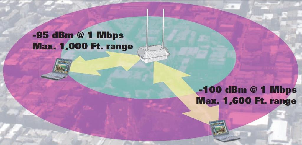
12 Sensitivity
13 Rates vs. Sensitivity/SINR Different modulation schemes have different constellations Denser constellations carry more bits/point higher rate increased BER needs larger SINR

14 802.11a/g OFDM
15 Multipath Propagation
16 Multipath Propagation Reflection - occurs when signal encounters a surface that is large relative to the wavelength of the signal Diffraction - occurs at the edge of an impenetrable body that is large compared to wavelength of radio wave Scattering occurs when incoming signal hits an object whose size in the order of the wavelength of the signal or less
17 Classical two-ray (ground model)
18 The Effects of Multipath Propagation Multiple copies of a signal may arrive at different phases If phases add destructively, the signal level relative to noise declines, making detection more difficult Intersymbol interference (ISI) One or more delayed copies of a pulse may arrive at the same time as the primary pulse for a subsequent bit

19 Types of Fading Fast fading Slow fading Flat fading Selective fading Rayleigh fading Rician fading
20 Fading in a mobile environment The term fading refers to the time variation of received signal power caused by changes in the transmission medium or paths. Atmospheric condition, such as rainfall The relative location of various obstacles changes over time
21 The fading channel Additive White Gaussian Noise (AWGN) channel thermal noise as well as electronics at the transmitter and receiver Rayleigh fading there are multiple indirect paths between transmitter and receiver and no distinct dominant path, such as an LOS path Rician fading there is a direct LOS path in additional to a number of indirect multipath signals

22 Fading: Small and Large scale
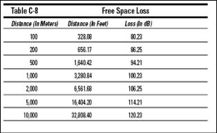
23 Path Loss Free Space propagation model: Two Ray (Ground Reflection) model: Log Distance model
24 Measured indoor path loss

25 Measured large-scale path loss
26 Path Loss Exponent for Different Environments
27 Signal Propagation Reflection Diffraction Scattering MultiPath Fading Shadow
28 Radio Propagation Model An empirical mathematical formulation for the: characterization of radio wave propagation as a function of : frequency, distance and other conditions A single model developed to predict the behavior of propagation for similar links under similar constraints formalize the way radio waves are propagated from one place to another Goal : predict the path loss along a link or the effective coverage area of a transmitter.
29 Propagation Modes Ground-wave propagation Sky-wave propagation Line-of-sight propagation
30 Ground Wave Propagation Follows contour of the earth Can Propagate considerable distances Frequencies up to 2 MHz Example : AM radio
31 Sky Wave Propagation Signal reflected from ionized layer of atmosphere back down to earth Signal can travel a number of hops, back and forth between ionosphere and earth s surface Reflection effect caused by refraction Examples Amateur radio CB radio
32 Line-of-Sight Propagation
33 Line-of-Sight Propagation Transmitting and receiving antennas must be within line of sight Satellite communication signal above 30 MHz not reflected by ionosphere Ground communication antennas within effective line of sight of each other due to refraction Refraction bending of microwaves by the atmosphere Velocity of electromagnetic wave is a function of the density of the medium When wave changes medium, speed changes Wave bends at the boundary between mediums
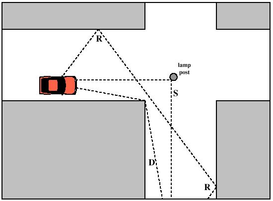
34 Fresnel Zone The area around the visual line-of-sight that radio waves spread out into after they leave the antenna. This area must be clear or else signal strength will weaken.
35 Fre s nell Zone (silent s ) We know that : Each wave-front point creates new circular waves Microwave beams widen, and Waves of one frequency can interfere with each other Fresnel zone theory: looks at a line from T to R, and at the space around that line that contributes to what is arriving at point R. Some waves travel directly from T to R, while Others travel on paths off axis. their path is longer, introducing a phase shift between the direct and indirect beam Whenever a phase shift is one full wavelength, you get constructive interference: the signals add up optimally Taking this approach and calculating accordingly, you find that: there are ring zones around the direct line T to R which contribute to the signal arriving at point T.
36 Fre s nell Zone (silent s ) There are many possible Fresnel zones, but we are concerned with zone 1. If this area were blocked by an obstruction, e.g. a tree or a building, the signal arriving at the far end would be diminished. We need to make sure that these zones be kept free of obstructions usually we check that 60 percent of the first Fresnel zone is kept free. A formula for calculating the radius of the first Fresnel zone: r 1 2 N d d 1 2 r N is the radius of the zone in meters N is the zone to calculate (i.e. N=1) d 1 and d 2 are distances from the obstructing screen at height h λ is the wavelength h<<d1,d2 and h>>λ N d d
37 At the Receiver Signal of Interest Account path loss + delayed reflections Interference Transmissions in the same or neighboring channels/frequencies Noise Thermal + System noise
38 Antennas The antenna provides three fundamental properties Gain Direction Polarization Gain: (pos/neg) increase in power Direction: transmission shape/pattern Polarization: electric field oscillation axis orientation


39 Antennas Near field Far field / Fraunhofer region
40 Antennas

41 Near/Far Field
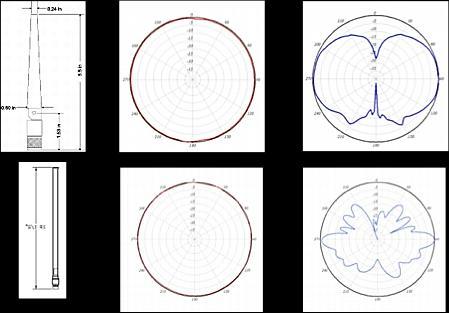

42 Omni-directional Antenna Patterns
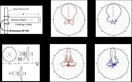

43 Directional Antennas Patterns
44 Received Power Effective Isotropic Radiated Power
45 Link Budget Predict the wireless link Estimate the Received Power => Rate Use db (additions & subtractions)

46 Link Budget
47 Link Budget Example We want to estimate the feasibility of a 5km link, with one access point and one client radio. The access point is connected to an omnidirectional antenna with 10dBi gain, while the client is connected to a sectorial antenna with 14dBi gain. The transmitting power of the AP is 100mW (or 20dBm) and its sensitivity is -89dBm. Cable losses for both the Rx and the Tx are the same at 2 dbm The transmitting power of the client is 30mW (or 15dBm) and its sensitivity is -82dBm.
48 Link Budget Example (cont.) Adding up all the gains and subtracting all the losses for the AP to client link gives: 20 dbm (TX Power Radio 1) + 10 dbi (Antenna Gain Radio 1) + 14 dbi (Antenna Gain Radio 2) - 2 dbm (Cable loses Rx) - 2 dbm (Cable loses Tx) db = Total Gain The path loss for a 5km link, considering free space loss is: Path Loss = log(5000) = 113 db Subtracting the path loss from the total gain 40 db db = -73 db Since -73dB is greater than the minimum receive sensitivity of the client radio (-82dBm), the signal level is just enough for the client radio to be able to hear the access point. There is 9dB of margin (82dB -73dB)
49 Link Budget Example (cont.) Next we calculate the link from the client back to the access point: 15 dbm (TX Power Radio 2) + 14 dbi (Antenna Gain Radio 2) + 10 dbi (Antenna Gain Radio 1) - 2 dbm (Cable loses Rx) - 2 dbm (Cable loses Tx) dbm = Total Gain Obviously, the path loss is the same on the return trip. So our received signal level on the access point side is: 35 db db = -78 db The receive sensitivity of the AP is -89dBm, this leaves us 11dB of margin (89dB -78dB) For the case of b (2,4GHz) E.I.R.P is 20dBm IS EVERYTHING OK? ANY PROBLEMS?. (think about it)
50 Link Budget (homework) Exercise 1: g, 54Mbps => -73dBm sens. Tx Power 20dBm EIRP 30dBm distance covered? Exercise 2: g 2km distance EIRP 20dBm achievable rate?
51 References (images/material) Wireless Communications - Principles and Practice (Second Edition), by Theodore S. Rappaport
52 APPENDIX
53 When using Watt: multiply, divide When using db/dbm: add, subtract Algebra The decibel (db) is a logarithmic unit that indicates the ratio of a physical quantity (usually power or intensity) relative to a specified or implied reference level Decibel suffix: dbm: indicates that the reference quantity is one milliwatt dbi : db(isotropic) the forward gain of an antenna compared with the hypothetical isotropic antenna, which uniformly distributes energy in all directions.

54 Decibel Relative measurement unit: Examples Rule of thumb: +10dB <=> x10
55 Decibel Rule of thumb: +3dB <=> x2 10 mw + 3 db = 20 mw 100 mw - 3dB = 50 mw 10 mw + 10 db = 100 mw 300 mw - 10 db = 30 mw

56 Decibel From db to units: -3dB = half the power in mw +3dB = double the power in mw -10dB = one tenth the power in mw +10dB = ten times the power in mw
57 more algebra
58 Basic Encoding Techniques Digital data to analog signal Amplitude-shift keying (ASK) Amplitude difference of carrier frequency Frequency-shift keying (FSK) Frequency difference near carrier frequency Phase-shift keying (PSK) Phase of carrier signal shifted
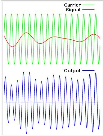
59 Amplitude modulation

60 Basic Encoding Techniques

61 Amplitude-Shift Keying One binary digit represented by presence of carrier, at constant amplitude Other binary digit represented by absence of carrier where the carrier signal is Acos(2πf c t)

62 Binary Frequency-Shift Keying (BFSK) Two binary digits represented by two different frequencies near the carrier frequency where f 1 and f 2 are offset from carrier frequency f c by equal but opposite amounts
63 Multiple Frequency-Shift Keying (MFSK) More than two frequencies are used More bandwidth efficient but more susceptible to error f i = f c + (2i 1 M)f d f c = the carrier frequency f d = the difference frequency M = number of different signal elements = 2 L L = number of bits per signal element
 Uses two phases to represent binary")
64 Phase-Shift Keying (PSK) Two-level PSK (BPSK) Uses two phases to represent binary digits
65 Phase-Shift Keying (PSK) Differential PSK (DPSK) Phase shift with reference to previous bit Binary 0 signal burst of same phase as previous signal burst Binary 1 signal burst of opposite phase to previous signal burst
 Each element represents more than")
66 Phase-Shift Keying (PSK) Four-level PSK (QPSK) Each element represents more than one bit

67 Phase-Shift Keying (PSK) Multilevel PSK Using multiple phase angles with each angle having more than one amplitude, multiple signals elements can be achieved D = modulation rate, baud R = data rate, bps M = number of different signal elements = 2 L L = number of bits per signal element
68 Performance Bandwidth of modulated signal (B T ) ASK, PSK FSK B T =(1+r)R B T =2DF+(1+r)R R = bit rate 0 < r < 1; related to how signal is filtered DF = f 2 -f c =f c -f 1

69 Performance Bandwidth of modulated signal (B T ) MPSK MFSK l = number of bits encoded per signal element M = number of different signal elements
70 Performance Bandwidth efficiency The ratio of data rate to transmission bandwidth (R/B T ) For MFSK, with the increase of M, the bandwidth efficiency is decreased. For MPSK, with the increase of M, the bandwidth efficiency is increased.
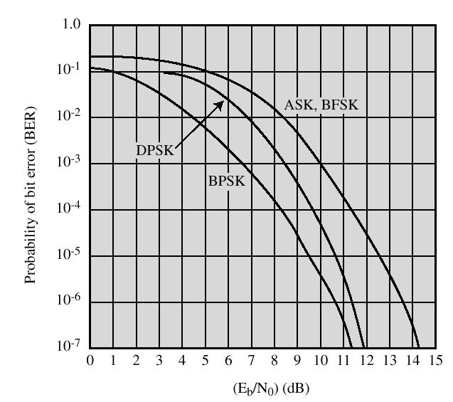
71 Performance
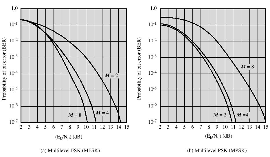
72 Performance
73 Performance Tradeoff between bandwidth efficiency and error performances: an increase in bandwidth efficiency results in an increase in error probability.
Antennas and Propagation. Chapter 5
 Antennas and Propagation Chapter 5 Introduction An antenna is an electrical conductor or system of conductors Transmission - radiates electromagnetic energy into space Reception - collects electromagnetic
Antennas and Propagation. Chapter 5
 Antennas and Propagation Chapter 5 Introduction An antenna is an electrical conductor or system of conductors Transmission - radiates electromagnetic energy into space Reception - collects electromagnetic
Antennas and Propagation
 Mobile Networks Module D-1 Antennas and Propagation 1. Introduction 2. Propagation modes 3. Line-of-sight transmission 4. Fading Slides adapted from Stallings, Wireless Communications & Networks, Second
Antennas and Propagation
 Antennas and Propagation Chapter 5 Introduction An antenna is an electrical conductor or system of conductors Transmission - radiates electromagnetic energy into space Reception - collects electromagnetic
Antennas & Propagation. CSG 250 Fall 2007 Rajmohan Rajaraman
 Antennas & Propagation CSG 250 Fall 2007 Rajmohan Rajaraman Introduction An antenna is an electrical conductor or system of conductors o Transmission - radiates electromagnetic energy into space o Reception
Session2 Antennas and Propagation
 Wireless Communication Presented by Dr. Mahmoud Daneshvar Session2 Antennas and Propagation 1. Introduction Types of Anttenas Free space Propagation 2. Propagation modes 3. Transmission Problems 4. Fading
Antennas and Propagation
 CMPE 477 Wireless and Mobile Networks Lecture 3: Antennas and Propagation Antennas Propagation Modes Line of Sight Transmission Fading in the Mobile Environment Introduction An antenna is an electrical
Project = An Adventure : Wireless Networks. Lecture 4: More Physical Layer. What is an Antenna? Outline. Page 1
 Project = An Adventure 18-759: Wireless Networks Checkpoint 2 Checkpoint 1 Lecture 4: More Physical Layer You are here Done! Peter Steenkiste Departments of Computer Science and Electrical and Computer
CHAPTER 6 THE WIRELESS CHANNEL
 CHAPTER 6 THE WIRELESS CHANNEL These slides are made available to faculty in PowerPoint form. Slides can be freely added, modified, and deleted to suit student needs. They represent substantial work on
Channel Modeling and Characteristics
 Channel Modeling and Characteristics Dr. Farid Farahmand Updated:10/15/13, 10/20/14 Line-of-Sight Transmission (LOS) Impairments The received signal is different from the transmitted signal due to transmission
Outline / Wireless Networks and Applications Lecture 5: Physical Layer Signal Propagation and Modulation
 Outline 18-452/18-750 Wireless Networks and Applications Lecture 5: Physical Layer Signal Propagation and Modulation Peter Steenkiste Carnegie Mellon University Spring Semester 2017 http://www.cs.cmu.edu/~prs/wirelesss17/
Antennas and Propagation. Prelude to Chapter 4 Propagation
 Antennas and Propagation Prelude to Chapter 4 Propagation Introduction An antenna is an electrical conductor or system of conductors for: Transmission - radiates electromagnetic energy into space (involves
Mobile and Wireless Networks Course Instructor: Dr. Safdar Ali
 Mobile and Wireless Networks Course Instructor: Dr. Safdar Ali BOOKS Text Book: William Stallings, Wireless Communications and Networks, Pearson Hall, 2002. BOOKS Reference Books: Sumit Kasera, Nishit
The Radio Channel. COS 463: Wireless Networks Lecture 14 Kyle Jamieson. [Parts adapted from I. Darwazeh, A. Goldsmith, T. Rappaport, P.
 The Radio Channel COS 463: Wireless Networks Lecture 14 Kyle Jamieson [Parts adapted from I. Darwazeh, A. Goldsmith, T. Rappaport, P. Steenkiste] Motivation The radio channel is what limits most radio
Radio Propagation Fundamentals
 Radio Propagation Fundamentals Concept of Electromagnetic Wave Propagation Mechanisms Modes of Propagation Propagation Models Path Profiles Link Budget Fading Channels Electromagnetic (EM) Waves EM Wave
UNIK4230: Mobile Communications Spring 2013
 UNIK4230: Mobile Communications Spring 2013 Abul Kaosher abul.kaosher@nsn.com Mobile: 99 27 10 19 1 UNIK4230: Mobile Communications Propagation characteristis of wireless channel Date: 07.02.2013 2 UNIK4230:
WIRELESS COMMUNICATIONS PRELIMINARIES
 WIRELESS COMMUNICATIONS Preliminaries Radio Environment Modulation Performance PRELIMINARIES db s and dbm s Frequency/Time Relationship Bandwidth, Symbol Rate, and Bit Rate 1 DECIBELS Relative signal strengths
Link Budget Calculation
 Link Budget Calculation Training materials for wireless trainers This 60 minute talk is about estimating wireless link performance by using link budget calculations. It also introduces the Radio Mobile
Contents. Telecom Service Chae Y. Lee. Data Signal Transmission Transmission Impairments Channel Capacity
 Data Transmission Contents Data Signal Transmission Transmission Impairments Channel Capacity 2 Data/Signal/Transmission Data: entities that convey meaning or information Signal: electric or electromagnetic
Planning a Microwave Radio Link
 8000 Lee Highway Falls Church, VA 22042 703-205-0600 www.ydi.com Planning a Microwave Radio Link By Michael F. Young President and CTO YDI Wireless Background Most installers know that clear line of sight
CHAPTER 2. Instructor: Mr. Abhijit Parmar Course: Mobile Computing and Wireless Communication ( )
") CHAPTER 2 Instructor: Mr. Abhijit Parmar Course: Mobile Computing and Wireless Communication (2170710) Syllabus Chapter-2.3 Modulation Techniques Reasons for Choosing Encoding Techniques Digital data,
CHAPTER 2 Instructor: Mr. Abhijit Parmar Course: Mobile Computing and Wireless Communication (2170710) Syllabus Chapter-2.3 Modulation Techniques Reasons for Choosing Encoding Techniques Digital data,
Intro to Radio Propagation,Antennas and Link Budget
 Intro to Radio Propagation,Antennas and Link Budget Training materials for wireless trainers Marco Zennaro and Ermanno Pietrosemoli T/ICT4D Laboratory ICTP Behavior of radio waves There are a few simple
Colubris Networks. Antenna Guide
 Colubris Networks Antenna Guide Creation Date: February 10, 2006 Revision: 1.0 Table of Contents 1. INTRODUCTION... 3 2. ANTENNA TYPES... 3 2.1. OMNI-DIRECTIONAL ANTENNA... 3 2.2. DIRECTIONAL ANTENNA...
Chapter 4 Radio Communication Basics
 Chapter 4 Radio Communication Basics Chapter 4 Radio Communication Basics RF Signal Propagation and Reception Basics and Keywords Transmitter Power and Receiver Sensitivity Power - antenna gain: G TX,
Lecture 3: Data Transmission
 Lecture 3: Data Transmission 1 st semester 1439-2017 1 By: Elham Sunbu OUTLINE Data Transmission DATA RATE LIMITS Transmission Impairments Examples DATA TRANSMISSION The successful transmission of data
Vehicle Networks. Wireless communication basics. Univ.-Prof. Dr. Thomas Strang, Dipl.-Inform. Matthias Röckl
 Vehicle Networks Wireless communication basics Univ.-Prof. Dr. Thomas Strang, Dipl.-Inform. Matthias Röckl Outline Wireless Signal Propagation Electro-magnetic waves Signal impairments Attenuation Distortion
Data and Computer Communications. Tenth Edition by William Stallings
 Data and Computer Communications Tenth Edition by William Stallings Data and Computer Communications, Tenth Edition by William Stallings, (c) Pearson Education - Prentice Hall, 2013 Wireless Transmission
LECTURE 3. Radio Propagation
 LECTURE 3 Radio Propagation 2 Simplified model of a digital communication system Source Source Encoder Channel Encoder Modulator Radio Channel Destination Source Decoder Channel Decoder Demod -ulator Components
Study of Factors which affect the Calculation of Co- Channel Interference in a Radio Link
 International Journal of Electronic and Electrical Engineering. ISSN 0974-2174 Volume 8, Number 2 (2015), pp. 103-111 International Research Publication House http://www.irphouse.com Study of Factors which
MSIT 413: Wireless Technologies Week 3
 MSIT 413: Wireless Technologies Week 3 Michael L. Honig Department of EECS Northwestern University January 2016 Why Study Radio Propagation? To determine coverage Can we use the same channels? Must determine
Introduction to Wireless Signal Propagation
 Introduction to Wireless Signal Propagation Raj Jain Professor of Computer Science and Engineering Washington University in Saint Louis Saint Louis, MO 63130 Jain@cse.wustl.edu Audio/Video recordings of
Unguided Transmission Media
 CS311 Data Communication Unguided Transmission Media by Dr. Manas Khatua Assistant Professor Dept. of CSE IIT Jodhpur E-mail: manaskhatua@iitj.ac.in Web: http://home.iitj.ac.in/~manaskhatua http://manaskhatua.github.io/
Introduction to wireless systems
 Introduction to wireless systems Wireless Systems a.a. 2014/2015 Un. of Rome La Sapienza Chiara Petrioli Department of Computer Science University of Rome Sapienza Italy Background- Wireless Systems What
Lecture 3 Concepts for the Data Communications and Computer Interconnection
 Lecture 3 Concepts for the Data Communications and Computer Interconnection Aim: overview of existing methods and techniques Terms used: -Data entities conveying meaning (of information) -Signals data
Wireless Communication Fundamentals Feb. 8, 2005
 Wireless Communication Fundamentals Feb. 8, 005 Dr. Chengzhi Li 1 Suggested Reading Chapter Wireless Communications by T. S. Rappaport, 001 (version ) Rayleigh Fading Channels in Mobile Digital Communication
Noise and Interference Limited Systems
 Chapter 3 Noise and Interference Limited Systems 47 Basics of link budgets Link budgets show how different components and propagation processes influence the available SNR Link budgets can be used to compute
Lecture 2 Physical Layer - Data Transmission
 DATA AND COMPUTER COMMUNICATIONS Lecture 2 Physical Layer - Data Transmission Mei Yang Based on Lecture slides by William Stallings 1 DATA TRANSMISSION The successful transmission of data depends on two
CALIFORNIA STATE UNIVERSITY, NORTHRIDGE FADING CHANNEL CHARACTERIZATION AND MODELING
 CALIFORNIA STATE UNIVERSITY, NORTHRIDGE FADING CHANNEL CHARACTERIZATION AND MODELING A graduate project submitted in partial fulfillment of the requirements For the degree of Master of Science in Electrical
Chapter 3. Mobile Radio Propagation
 Chapter 3 Mobile Radio Propagation Based on the slides of Dr. Dharma P. Agrawal, University of Cincinnati and Dr. Andrea Goldsmith, Stanford University Propagation Mechanisms Outline Radio Propagation
UNIT- 7. Frequencies above 30Mhz tend to travel in straight lines they are limited in their propagation by the curvature of the earth.
 UNIT- 7 Radio wave propagation and propagation models EM waves below 2Mhz tend to travel as ground waves, These wave tend to follow the curvature of the earth and lose strength rapidly as they travel away
Antenna Basics. Antennas. A guide to effective antenna use
 A guide to effective antenna use Antennas Antennas transmit radio signals by converting radio frequency electrical currents into electromagnetic waves. Antennas receive the signals by converting the electromagnetic
ECE 476/ECE 501C/CS Wireless Communication Systems Winter Lecture 6: Fading
 ECE 476/ECE 501C/CS 513 - Wireless Communication Systems Winter 2004 Lecture 6: Fading Last lecture: Large scale propagation properties of wireless systems - slowly varying properties that depend primarily
ECE 476/ECE 501C/CS Wireless Communication Systems Winter Lecture 6: Fading
 ECE 476/ECE 501C/CS 513 - Wireless Communication Systems Winter 2005 Lecture 6: Fading Last lecture: Large scale propagation properties of wireless systems - slowly varying properties that depend primarily
Data and Computer Communications Chapter 4 Transmission Media
 Data and Computer Communications Chapter 4 Transmission Media Ninth Edition by William Stallings Data and Computer Communications, Ninth Edition by William Stallings, (c) Pearson Education - Prentice Hall,
EC 554 Data Communications
 EC 554 Data Communications Mohamed Khedr http://webmail. webmail.aast.edu/~khedraast.edu/~khedr Syllabus Tentatively Week 1 Week 2 Week 3 Week 4 Week 5 Week 6 Week 7 Week 8 Week 9 Week 10 Week 11 Week
Wireless Networked Systems. Lec #1b: PHY Basics
 Wireless Networked Systems CS 795/895 - Spring 2013 Lec #1b: PHY Basics Tamer Nadeem Dept. of Computer Science Wireless Communication Page 2 Spring 2013 CS 795/895 - Wireless Networked Systems Radio Signal
Unit 3 - Wireless Propagation and Cellular Concepts
 X Courses» Introduction to Wireless and Cellular Communications Unit 3 - Wireless Propagation and Cellular Concepts Course outline How to access the portal Assignment 2. Overview of Cellular Evolution
ECE 476/ECE 501C/CS Wireless Communication Systems Winter Lecture 6: Fading
 ECE 476/ECE 501C/CS 513 - Wireless Communication Systems Winter 2003 Lecture 6: Fading Last lecture: Large scale propagation properties of wireless systems - slowly varying properties that depend primarily
6 Radio and RF. 6.1 Introduction. Wavelength (m) Frequency (Hz) Unit 6: RF and Antennas 1. Radio waves. X-rays. Microwaves. Light
 Frequency (Hz) Unit 6: RF and Antennas 1. Radio waves. X-rays. Microwaves. Light") 6 Radio and RF Ref: http://www.asecuritysite.com/wireless/wireless06 6.1 Introduction The electromagnetic (EM) spectrum contains a wide range of electromagnetic waves, from radio waves up to X-rays (as
6 Radio and RF Ref: http://www.asecuritysite.com/wireless/wireless06 6.1 Introduction The electromagnetic (EM) spectrum contains a wide range of electromagnetic waves, from radio waves up to X-rays (as
Motorola Wireless Broadband Technical Brief OFDM & NLOS
 technical BRIEF TECHNICAL BRIEF Motorola Wireless Broadband Technical Brief OFDM & NLOS Splitting the Data Stream Exploring the Benefits of the Canopy 400 Series & OFDM Technology in Reaching Difficult
Data Communication. Chapter 3 Data Transmission
 Data Communication Chapter 3 Data Transmission ١ Terminology (1) Transmitter Receiver Medium Guided medium e.g. twisted pair, coaxial cable, optical fiber Unguided medium e.g. air, water, vacuum ٢ Terminology
Bit Error Rate Assessment of Digital Modulation Schemes on Additive White Gaussian Noise, Line of Sight and Non Line of Sight Fading Channels
 International Journal of Engineering Science Invention ISSN (Online): 2319 6734, ISSN (Print): 2319 6726 Volume 3 Issue 8 ǁ August 2014 ǁ PP.06-10 Bit Error Rate Assessment of Digital Modulation Schemes
UNIT Derive the fundamental equation for free space propagation?
 UNIT 8 1. Derive the fundamental equation for free space propagation? Fundamental Equation for Free Space Propagation Consider the transmitter power (P t ) radiated uniformly in all the directions (isotropic),
Using the epmp Link Budget Tool
 Using the epmp Link Budget Tool The epmp Series Link Budget Tool can offer a help to determine the expected performances in terms of distances of a epmp Series system operating in line-of-sight (LOS) propagation
Structure of the Lecture
 Structure of the Lecture Chapter 2 Technical Basics: Layer 1 Methods for Medium Access: Layer 2 Representation of digital signals on an analogous medium Signal propagation Characteristics of antennas Chapter
Antenna & Propagation. Basic Radio Wave Propagation
 For updated version, please click on http://ocw.ump.edu.my Antenna & Propagation Basic Radio Wave Propagation by Nor Hadzfizah Binti Mohd Radi Faculty of Electric & Electronics Engineering hadzfizah@ump.edu.my
L(f) = = (f) G(f) L2(f) Transmission Impairments: Attenuation (cont.)
 = = (f) G(f) L2(f) Transmission Impairments: Attenuation (cont.)") Transmission Impairments: Attenuation (cont.) how many times the put signal has attenuated relative to the input signal should be in L(f) (f) (f) A A in (f) (f) how many times the put signal has been amplified
Transmission Impairments: Attenuation (cont.) how many times the put signal has attenuated relative to the input signal should be in L(f) (f) (f) A A in (f) (f) how many times the put signal has been amplified
Revision of Lecture One
 Revision of Lecture One System blocks and basic concepts Multiple access, MIMO, space-time Transceiver Wireless Channel Signal/System: Bandpass (Passband) Baseband Baseband complex envelope Linear system:
UNDER STANDING RADIO FREQUENCY Badger Meter, Inc.
 UNDER STANDING RADIO FREQUENCY UNDERSTANDING RADIO FREQUENCY Regional Sales Meeting March 1-2, 2011 Brian Fiut Sr. Product Manager Itron Inc. Liberty Lake, WA August 25, 2010 RADIO PROPAGATION Radio consists
Digital modulation techniques
 Outline Introduction Signal, random variable, random process and spectra Analog modulation Analog to digital conversion Digital transmission through baseband channels Signal space representation Optimal
Lecture 1 Wireless Channel Models
 MIMO Communication Systems Lecture 1 Wireless Channel Models Prof. Chun-Hung Liu Dept. of Electrical and Computer Engineering National Chiao Tung University Spring 2017 2017/3/2 Lecture 1: Wireless Channel
E-716-A Mobile Communications Systems. Lecture #2 Basic Concepts of Wireless Transmission (p1) Instructor: Dr. Ahmad El-Banna
 Instructor: Dr. Ahmad El-Banna") October 2014 Ahmad El-Banna Integrated Technical Education Cluster At AlAmeeria E-716-A Mobile Communications Systems Lecture #2 Basic Concepts of Wireless Transmission (p1) Instructor: Dr. Ahmad El-Banna
October 2014 Ahmad El-Banna Integrated Technical Education Cluster At AlAmeeria E-716-A Mobile Communications Systems Lecture #2 Basic Concepts of Wireless Transmission (p1) Instructor: Dr. Ahmad El-Banna
Outline / Wireless Networks and Applications Lecture 3: Physical Layer Signals, Modulation, Multiplexing. Cartoon View 1 A Wave of Energy
 Outline 18-452/18-750 Wireless Networks and Applications Lecture 3: Physical Layer Signals, Modulation, Multiplexing Peter Steenkiste Carnegie Mellon University Spring Semester 2017 http://www.cs.cmu.edu/~prs/wirelesss17/
Course 2: Channels 1 1
 Course 2: Channels 1 1 "You see, wire telegraph is a kind of a very, very long cat. You pull his tail in New York and his head is meowing in Los Angeles. Do you understand this? And radio operates exactly
Data and Computer Communications Chapter 3 Data Transmission
 Data and Computer Communications Chapter 3 Data Transmission Eighth Edition by William Stallings Transmission Terminology data transmission occurs between a transmitter & receiver via some medium guided
Data and Computer Communications. Chapter 3 Data Transmission
 Data and Computer Communications Chapter 3 Data Transmission Data Transmission quality of the signal being transmitted The successful transmission of data depends on two factors: characteristics of the
ELEC-E7120 Wireless Systems Weekly Exercise Problems 5
 ELEC-E7120 Wireless Systems Weekly Exercise Problems 5 Problem 1: (Range and rate in Wi-Fi) When a wireless station (STA) moves away from the Access Point (AP), the received signal strength decreases and
COMP211 Physical Layer
 COMP211 Physical Layer Data and Computer Communications 7th edition William Stallings Prentice Hall 2004 Computer Networks 5th edition Andrew S.Tanenbaum, David J.Wetherall Pearson 2011 Material adapted
Chapter 15: Radio-Wave Propagation
 Chapter 15: Radio-Wave Propagation MULTIPLE CHOICE 1. Radio waves were first predicted mathematically by: a. Armstrong c. Maxwell b. Hertz d. Marconi 2. Radio waves were first demonstrated experimentally
Point to point Radiocommunication
 Point to point Radiocommunication SMS4DC training seminar 7 November 1 December 006 1 Technical overview Content SMS4DC Software link calculation Exercise 1 Point-to-point Radiocommunication Link A Radio
CHAPTER 2 WIRELESS CHANNEL
 CHAPTER 2 WIRELESS CHANNEL 2.1 INTRODUCTION In mobile radio channel there is certain fundamental limitation on the performance of wireless communication system. There are many obstructions between transmitter
INTRODUCTION TO RF PROPAGATION
 INTRODUCTION TO RF PROPAGATION John S. Seybold, Ph.D.,WILEY- 'interscience JOHN WILEY & SONS, INC. Preface XIII 1. Introduction 1.1 Frequency Designations 1 1.2 Modes of Propagation 3 1.2.1 Line-of-Sight
Revision of Lecture One
 Revision of Lecture One System block Transceiver Wireless Channel Signal / System: Bandpass (Passband) Baseband Baseband complex envelope Linear system: complex (baseband) channel impulse response Channel:
MSIT 413: Wireless Technologies Week 3
 MSIT 413: Wireless Technologies Week 3 Michael L. Honig Department of EECS Northwestern University October 2017 Why Study Radio Propagation? To determine coverage Can we use the same channels? Must determine
Point-to-Point Communications
 Point-to-Point Communications Key Aspects of Communication Voice Mail Tones Alphabet Signals Air Paper Media Language English/Hindi English/Hindi Outline of Point-to-Point Communication 1. Signals basic
Probabilistic Link Properties. Octav Chipara
 Probabilistic Link Properties Octav Chipara Signal propagation Propagation in free space always like light (straight line) Receiving power proportional to 1/d² in vacuum much more in real environments
CS263: Wireless Communications and Sensor Networks
 CS263: Wireless Communications and Sensor Networks Matt Welsh Lecture 3: Antennas, Propagation, and Spread Spectrum September 30, 2004 2004 Matt Welsh Harvard University 1 Today's Lecture Antennas and
Lecture - 06 Large Scale Propagation Models Path Loss
 Fundamentals of MIMO Wireless Communication Prof. Suvra Sekhar Das Department of Electronics and Communication Engineering Indian Institute of Technology, Kharagpur Lecture - 06 Large Scale Propagation
BER ANALYSIS OF WiMAX IN MULTIPATH FADING CHANNELS
 BER ANALYSIS OF WiMAX IN MULTIPATH FADING CHANNELS Navgeet Singh 1, Amita Soni 2 1 P.G. Scholar, Department of Electronics and Electrical Engineering, PEC University of Technology, Chandigarh, India 2
Ad hoc and Sensor Networks Chapter 4: Physical layer. Holger Karl
 Ad hoc and Sensor Networks Chapter 4: Physical layer Holger Karl Goals of this chapter Get an understanding of the peculiarities of wireless communication Wireless channel as abstraction of these properties
Written Exam Channel Modeling for Wireless Communications - ETIN10
 Written Exam Channel Modeling for Wireless Communications - ETIN10 Department of Electrical and Information Technology Lund University 2017-03-13 2.00 PM - 7.00 PM A minimum of 30 out of 60 points are
DATA TRANSMISSION. ermtiong. ermtiong
 DATA TRANSMISSION Analog Transmission Analog signal transmitted without regard to content May be analog or digital data Attenuated over distance Use amplifiers to boost signal Also amplifies noise DATA
Chapter 2 Channel Equalization
 Chapter 2 Channel Equalization 2.1 Introduction In wireless communication systems signal experiences distortion due to fading [17]. As signal propagates, it follows multiple paths between transmitter and
Lecture 3: Wireless Physical Layer: Modulation Techniques. Mythili Vutukuru CS 653 Spring 2014 Jan 13, Monday
 Lecture 3: Wireless Physical Layer: Modulation Techniques Mythili Vutukuru CS 653 Spring 2014 Jan 13, Monday Modulation We saw a simple example of amplitude modulation in the last lecture Modulation how
Chapter 1 Introduction
 Wireless Information Transmission System Lab. Chapter 1 Introduction National Sun Yat-sen University Table of Contents Elements of a Digital Communication System Communication Channels and Their Wire-line
WIRELESS TRANSMISSION
 COMP 635: WIRELESS NETWORKS WIRELESS TRANSMISSION Jasleen Kaur Fall 205 Outline Frequenc Spectrum Ø Usage and Licensing Signals and Antennas Ø Propagation Characteristics Multipleing Ø Space, Frequenc,
Lecture Fundamentals of Data and signals
 IT-5301-3 Data Communications and Computer Networks Lecture 05-07 Fundamentals of Data and signals Lecture 05 - Roadmap Analog and Digital Data Analog Signals, Digital Signals Periodic and Aperiodic Signals
Review of Path Loss models in different environments
 Review of Path Loss models in different environments Mandeep Kaur 1, Deepak Sharma 2 1 Computer Scinece, Kurukshetra Institute of Technology and Management, Kurukshetra 2 H.O.D. of CSE Deptt. Abstract
High Speed Data Downlink for NSF Space Weather CubeSats
 High Speed Data Downlink for NSF Space Weather CubeSats National Science Foundation Meeting Monday August 31, 2009 Charles Swenson Satellite Data Flow Onboard Instruments R collected Spacecraft Memory
Wireless Physical Layer Concepts: Part II
 Wireless Physical Layer Concepts: Part II Raj Jain Professor of CSE Washington University in Saint Louis Saint Louis, MO 63130 Jain@cse.wustl.edu Audio/Video recordings of this lecture are available at:
Performance Evaluation Of Digital Modulation Techniques In Awgn Communication Channel
 Performance Evaluation Of Digital Modulation Techniques In Awgn Communication Channel Oyetunji S. A 1 and Akinninranye A. A 2 1 Federal University of Technology Akure, Nigeria 2 MTN Nigeria Abstract The
Wireless Channel Propagation Model Small-scale Fading
 Wireless Channel Propagation Model Small-scale Fading Basic Questions T x What will happen if the transmitter - changes transmit power? - changes frequency? - operates at higher speed? Transmit power,
November 24, 2010xx. Introduction
 Path Analysis XXXXXXXXX Ref Number: XXXXXXX Introduction This report is an analysis of the proposed XXXXXXXXX network between XXXXXXX and XXXXXXX. The primary aim was to investigate the frequencies and
# DEFINITIONS TERMS. 2) Electrical energy that has escaped into free space. Electromagnetic wave
 Electrical energy that has escaped into free space. Electromagnetic wave") CHAPTER 14 ELECTROMAGNETIC WAVE PROPAGATION # DEFINITIONS TERMS 1) Propagation of electromagnetic waves often called radio-frequency (RF) propagation or simply radio propagation. Free-space 2) Electrical
CHAPTER 14 ELECTROMAGNETIC WAVE PROPAGATION # DEFINITIONS TERMS 1) Propagation of electromagnetic waves often called radio-frequency (RF) propagation or simply radio propagation. Free-space 2) Electrical
Wireless Communication Technology
 PART TWO Wireless Communication Technology CHAPTER5 ANTENNAS AND PROPAGATION 5.1 Antennas Radiation Patterns Antenna Types Antenna Gain 5.2 Propagation Modes Ground Wave Propagation Sky Wave Propagation
Wireless Sensor Networks 4th Lecture
 Wireless Sensor Networks 4th Lecture 07.11.2006 Christian Schindelhauer schindel@informatik.uni-freiburg.de 1 Amplitude Representation Amplitude representation of a sinus curve s(t) = A sin(2π f t + ϕ)
Mobile Radio Propagation Channel Models
 Wireless Information Transmission System Lab. Mobile Radio Propagation Channel Models Institute of Communications Engineering National Sun Yat-sen University Table of Contents Introduction Propagation
CS441 Mobile & Wireless Computing Communication Basics
 Department of Computer Science Southern Illinois University Carbondale CS441 Mobile & Wireless Computing Communication Basics Dr. Kemal Akkaya E-mail: kemal@cs.siu.edu Kemal Akkaya Mobile & Wireless Computing
William Stallings Data and Computer Communications 7 th Edition. Chapter 4 Transmission Media
 William Stallings Data and Computer Communications 7 th Edition Chapter 4 Transmission Media Overview Guided - wire Unguided - wireless Characteristics and quality determined by medium and signal For guided,
TSEK02: Radio Electronics Lecture 6: Propagation and Noise. Ted Johansson, EKS, ISY
 TSEK02: Radio Electronics Lecture 6: Propagation and Noise Ted Johansson, EKS, ISY 2 Propagation and Noise - Channel and antenna: not in the Razavi book - Noise: 2.3 The wireless channel The antenna Signal