Mobile and Wireless Networks Course Instructor: Dr. Safdar Ali
|
|
|
- Britney Gray
- 5 years ago
- Views:
Transcription
1 Mobile and Wireless Networks Course Instructor: Dr. Safdar Ali

2 BOOKS Text Book: William Stallings, Wireless Communications and Networks, Pearson Hall, 2002.

3 BOOKS Reference Books: Sumit Kasera, Nishit Narang, 3G Networks Architecture, Protocols, and Procedures,Tata McGraw-Hill Education, 2004.
4 COURSE EVALUATION Quiz: 10% Assignments: 20% Mid Term: 20% Final Exam: 50%
5 Communication Networks
6 TYPES OF COMMUNICATION NETWORKS Local area network (LAN) Wide area network (WAN)
7 SWITCHING NETWORK For transmission of data beyond a local area, communication is typically achieved by transmitting data from source to destination through a network of intermediate switching nodes. The switching nodes are not concerned with the content of the data; rather their purpose is to provide a switching facility that will move the data from node to node until they reach their destination.
8 SWITCHING NETWORK Information from station A intended for station F. Data is sent to node 4.
9 SWITCHING NETWORK It may then be routed via nodes 5 and 6 or nodes 7 and 6 to the destination.
10 SWITCHING NETWORK Some nodes connect only to other nodes (e.g., 5 and 7). Their sole task is the internal (to the network) switching of information.
11 SWITCHING NETWORK Other nodes have one or more stations attached as well; in addition to their switching functions, such nodes accept information from and deliver information to the attached stations.
12 SWITCHING NETWORK Node-station links are generally dedicated point-topoint links.
13 SWITCHING NETWORK Usually, the network is not fully connected; that is, there is not a direct link between every possible pair of nodes. However, it is always desirable to have more than one possible path through the network for each pair of stations. This enhances the reliability of the network.
14 SWITCHING NETWORK Two quite different technologies are used in wide area switched networks: Circuit switching and Packet switching. These two technologies differ in the way the nodes switch information from one link to another on the way from source to destination.
15 Circuit and Packet switching??
16 SWITCHING TECHNIQUES Circuit switching Dedicated communications path between two stations The most common example of circuit switching is the telephone network. Packet switching Each node determines next leg of transmission for each packet
17 CIRCUIT SWITCHING Station A wants to send data to station E.
18 PHASES OF CIRCUIT SWITCHING Circuit establishment An end to end circuit is established through switching nodes Information Transfer Information transmitted through the network Data may be analog voice, digitized voice, or binary data Circuit disconnect Circuit is terminated Each node deallocates dedicated resources
19 CONNECTION OVER A PUBLIC CIRCUIT- SWITCHING NETWORK
20 Disadvantages?
21 CIRCUIT SWITCHING Can be inefficient Channel capacity dedicated for duration of connection even no data is being transferred. Utilization not 100%
22 PACKET SWITCHING Data is transmitted in blocks, called packets A typical upper bound on packet length is 1000 octets (bytes). If a source has a longer message to send, the message is broken up into a series of packets
23 PACKET SWITCHING The control information, includes the information that the network requires in order to be able to route the packet through the network and deliver it to the intended destination.
24
25 PACKET SWITCHING
26 Advantages?
27 PACKET SWITCHING ADVANTAGES Line efficiency is greater Many packets over time can dynamically share the same node to node link Unlike circuit-switching networks that block calls when traffic is heavy, packet-switching still accepts packets, but with increased delivery delay
28 Disadvantages?
29 PACKET SWITCHING DISADVANTAGES Overall packet delay can vary substantially This is referred to as jitter Caused by differing packet sizes, routes taken and varying delay in the switches Each packet requires overhead information Includes destination and sequencing information Reduces communication capacity More processing required at each node
30 Antennas and Propagation
31 What is Antenna???
32 INTRODUCTION An antenna is an electrical conductor or system of conductors Transmission - radiates electromagnetic energy into space Reception - collects electromagnetic energy from space In two-way communication, the same antenna can be used for transmission and reception
33 What is Radiation Pattern??
34 RADIATION PATTERNS An antenna may radiates power in all directions but, typically, does not perform equally well in all directions. A common way to characterize the performance of an antenna is the radiation pattern, which is a graphical representation of the radiation properties of an antenna as a function of space coordinates.
35 RADIATION PATTERNS The simplest pattern is produced by an idealized antenna known as the isotropic antenna. An isotropic antenna is a point in space that radiates power in all directions equally. The actual radiation pattern for the isotropic antenna is a sphere with the antenna at the center.
36 RADIATION PATTERNS Figure (b) shows the radiation pattern of another idealized antenna. This is a directional antenna in which there is a preferred direction of radiation.
37 RADIATION PATTERNS The isotropic antenna produces an omni-directional radiation pattern of equal strength in all directions, so the A and B vectors are of equal length.
38 RADIATION PATTERNS For the antenna pattern of Figure (b), the B vector is longer than the A vector, indicating that more power is radiated in the B direction than in the A direction.
39 Any Example of omni-directional and directional antennas??
40 TYPES OF ANTENNAS Isotropic antenna (idealized) Radiates power equally in all directions Dipole antennas Half-wave dipole antenna (or Hertz antenna) Quarter-wave vertical antenna (or Marconi antenna) Parabolic Reflective Antenna

41 DIPOLE ANTENNA
42 PARABOLIC REFLECTIVE ANTENNA An important type of antenna is the parabolic reflective antenna. Used in terrestrial microwave and satellite applications.
43 PARABOLIC REFLECTIVE ANTENNA If a source of electromagnetic energy is placed at the focus of the paraboloid, and if the paraboloid is a reflecting surface, then the wave will bounce back in lines parallel to the axis of the paraboloid.
44
45 Antenna Gain??
46 ANTENNA GAIN Antenna gain is a measure of the directionality of an antenna. Antenna gain is defined as the power output, in a particular direction, compared to that produced in any direction by a perfect omni-directional antenna (isotropic antenna). Increased power is radiated in one direction by reducing the power radiated in other directions.
47 Effective Aperture???
48 EFFECTIVE APERTURE A practical antenna with a physical aperture area A will not deliver the total power to the receiver. Some of the energy incident on the aperture is reflected away from the antenna, and some is absorbed by lossy components. The reduction in efficiency is described by the effective aperture.
49 ANTENNA GAIN Relationship between antenna gain and effective area G G = antenna gain A e = effective area f = carrier frequency c = speed of light (3 x10 8 m/s) = carrier wavelength 4 A e 2 4 f c 2 2 A e
50 NUMERICAL For a parabolic reflective antenna with a diameter of 2 m, operating frequency at 12 GHz, what is the effective area of and the antenna gain??

51 HINTS A = л r square
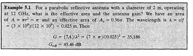
52 SOLUTION
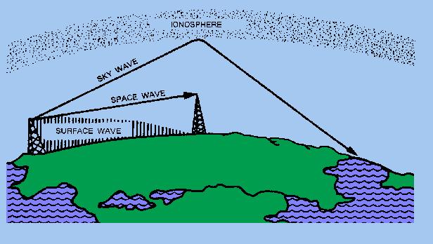
53 PROPAGATION MODES A signal radiated from an antenna travels along one of three routes: Ground-wave propagation Sky-wave propagation Line-of-sight propagation
54 GROUND WAVE PROPAGATION
55 GROUND WAVE PROPAGATION Ground wave propagation more or less follows the contour of the earth. It can propagate considerable distances, well over the visual horizon. This effect is found in frequencies up to about 2 MHz. Example AM radio
56 SKY WAVE PROPAGATION
57 SKY WAVE PROPAGATION
58 SKY WAVE PROPAGATION Sky wave propagation is used for international broadcasts such as BBC and Voice of America. Signal reflected from ionized layer of atmosphere back down to earth. Signal can travel a number of hops, back and forth between ionosphere and earth s surface. With this propagation mode, a signal can be picked up thousands of kilometers from the transmitter.
59 LINE-OF-SIGHT PROPAGATION
60 LINE-OF-SIGHT PROPAGATION Above 30 MHz, neither ground wave nor sky wave propagation modes operate. Transmitting and receiving antennas must be within line of sight Satellite communication signal above 30 MHz not reflected by ionosphere

61 OPTICAL AND RADIO HORIZON
62 LINE-OF-SIGHT EQUATIONS Optical line of sight d h Effective, or radio, line of sight d = distance between antenna and horizon (km) h = antenna height (m) d h K = adjustment factor to account for refraction, rule of thumb K = 4/3
63 LINE-OF-SIGHT PROPAGATION Maximum distance between two antennas for LOS propagation: d h 1 = height of antenna one h 2 = height of antenna two 3.57 h h 1 2
64 NUMERICAL What will be the maximum distance between two antennas for LOS transmission if one antenna is 100 m high and other is at ground level. Ans = 41 km Now suppose that the receiving antenna is 10 m high. To achieve the same distance, how high must the transmitting antenna be? Ans = 46.2m
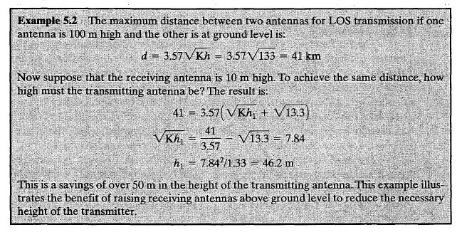
65 SOLUTION
66 LOS WIRELESS TRANSMISSION IMPAIRMENTS With any communications system, the signal that is received will differ from the signal that is transmitted, due to various transmission impairments. For digital data, bit errors are introduced: A binary 1 is transformed into a binary 0, and vice versa.
67 LOS WIRELESS TRANSMISSION IMPAIRMENTS Attenuation and attenuation distortion Free space loss Noise Atmospheric absorption Multipath Refraction Thermal noise
68 ATTENUATION The strength of a signal falls off with distance over any transmission medium.
69 ATTENUATION Attenuation factors for unguided media: Received signal must have sufficient strength so that circuitry in the receiver can interpret the signal Signal must maintain a level sufficiently higher than noise to be received without error Attenuation is greater at higher frequencies, causing distortion
70 ATTENUATION The first and second factors are dealt with by attention to signal strength and the use of amplifiers or repeaters. For a point-to-point transmission (one transmitter and one receiver), the signal strength of the transmitter must be strong enough to be received intelligibly, but not so strong as to overload the circuitry of the transmitter or receiver, which would cause distortion.

71 ATTENUATION Beyond a certain distance, the attenuation becomes unacceptably great, and repeaters or amplifiers are used to boost the signal at regular intervals.
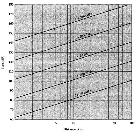
72 FREE SPACE LOSS Free space loss can be express in terms of the ratio of the radiated power Pt to the power Pr, received by the antenna.
73 FREE SPACE LOSS Free space loss, ideal isotropic antenna P t P r 2 4 d 4 fd P t = signal power at transmitting antenna P r = signal power at receiving antenna = carrier wavelength d = propagation distance between antennas c = speed of light (3 x10 8 m/s) where d and are in the same units (e.g., meters) 2 c 2 2
74 FREE SPACE LOSS Free space loss equation can be recast: L db 10log Pt P r 20log 4 d 20log d db 20log 4 fd 20log 20log c f 20log d db
75
76 FREE SPACE LOSS Free space loss accounting for gain of other antennas P t P r d d cd G G r G t = gain of transmitting antenna G r = gain of receiving antenna A t = effective area of transmitting antenna A r = effective area of receiving antenna t 2 A r A t f 2 A r 2 A t

77 FREE SPACE LOSS
78 FREE SPACE LOSS Free space loss accounting for gain of other antennas can be recast as L db 20log d 10log A A 20log f 20log d 10log A A t dB 20log t r r
79 NOISE For any data transmission event, the received signal will consist of the: transmitted signal, modified by the various distortions imposed by the transmission system, plus additional unwanted signals that are inserted somewhere between transmission and reception. These unwanted signals are referred to as noise.
80 CATEGORIES OF NOISE Thermal Noise Crosstalk Impulse Noise
81 THERMAL NOISE Thermal noise is due to thermal agitation of electrons. It is present in all electronic devices and transmission media and is a function of temperature.
82 THERMAL NOISE Amount of thermal noise to be found in a bandwidth of 1Hz in any device or conductor is: N kt 0 W/Hz N 0 = noise power density in watts per 1 Hz of bandwidth k = Boltzmann's constant = x10-23 J/K T = temperature, in kelvins (absolute temperature)
83 THERMAL NOISE Noise is assumed to be independent of frequency Thermal noise present in a bandwidth of B Hertz (in watts): or, in decibel-watts N ktb N 10log k 10 log T 10log B dbw 10 log T 10log B
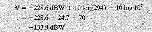
84 NUMERICAL
85 CROSSTALK Crosstalk has been experienced by anyone who, while using the telephone, has been able to hear another conversation. It is an unwanted coupling between signal paths. Crosstalk can also occur when unwanted signals are picked up by microwave antennas.
86 IMPULSE NOISE Impulse noise is consist of irregular pulses or noise spikes of short duration and of relatively high amplitude. It is generated from a variety of causes, including external electromagnetic disturbances, such as lightning, and faults and flaws in the communications system.
87 THE EXPRESSION EB/NO There is a parameter related to SNR that is more convenient for determining digital data rates and error rates and that is the standard quality measure for digital communication system performance. The parameter is the ratio of signal energy per bit to noise power density per Hertz, (Eb / No) The energy per bit in a signal is given by Eb = STb,
88 THE EXPRESSION EB/NO E b N 0 S / R N 0 S ktr where S is the signal power and Tb is the time required to send one bit. The data rate R is just R = 1/Tb.
89 THE EXPRESSION EB/NO In several instances, the noise is sufficient to alter the value of a bit. If the data rate were doubled, the bits would be more tightly packed together, and the same passage of noise might destroy two bits. Thus, for constant signal and noise strength, an increase in data rate increases the error rate.
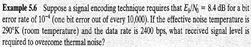
90 NUMERICAL
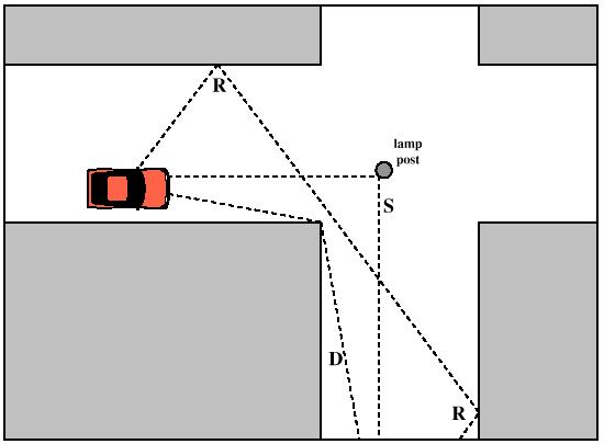
91 MULTIPATH In mobile telephony, there are obstacles in abundance.
92 MULTIPATH The signal can be reflected by obstacles so that multiple copies of the signal with varying delays can be received. In fact, in extreme cases, the receiver may capture only reflected signals and not the direct signal.
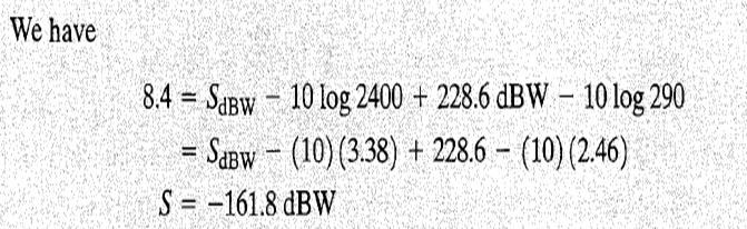
93 ATMOSPHERIC ABSORPTION An additional loss between the transmitting and receiving antennas is atmospheric absorption. Water vapor and oxygen contribute most to attenuation. A peak attenuation occurs in the vicinity of 22 GHz due to water vapor. The presence of oxygen results in an absorption peak in the vicinity of 60 GHz
94 ATMOSPHERIC ABSORPTION Rain and fog cause scattering of radio waves that results in attenuation.
95 ATMOSPHERIC ABSORPTION
96 MULTIPATH Reinforcement and cancellation of the signal resulting from the signal following multiple paths can be controlled for communication between fixed, well-sited antennas, and between satellites and fixed ground stations. One exception is when the path goes across water, where the wind keeps the reflective surface of the water in motion.
97 MULTIPATH For mobile telephony and communication to antennas that are not well sited, multipath considerations can be paramount.
98 MULTIPATH PROPAGATION
99 MULTIPATH PROPAGATION Reflection - occurs when signal encounters a surface that is large relative to the wavelength of the signal. Diffraction - occurs at the edge of an impenetrable body that is large compared to wavelength of radio wave.
100 MULTIPATH PROPAGATION Scattering occurs when incoming signal hits an object whose size in the order of the wavelength of the signal or less.
Antennas and Propagation. Chapter 5
 Antennas and Propagation Chapter 5 Introduction An antenna is an electrical conductor or system of conductors Transmission - radiates electromagnetic energy into space Reception - collects electromagnetic
Antennas and Propagation. Chapter 5
 Antennas and Propagation Chapter 5 Introduction An antenna is an electrical conductor or system of conductors Transmission - radiates electromagnetic energy into space Reception - collects electromagnetic
Antennas and Propagation
 CMPE 477 Wireless and Mobile Networks Lecture 3: Antennas and Propagation Antennas Propagation Modes Line of Sight Transmission Fading in the Mobile Environment Introduction An antenna is an electrical
Antennas and Propagation
 Mobile Networks Module D-1 Antennas and Propagation 1. Introduction 2. Propagation modes 3. Line-of-sight transmission 4. Fading Slides adapted from Stallings, Wireless Communications & Networks, Second
Antennas and Propagation
 Antennas and Propagation Chapter 5 Introduction An antenna is an electrical conductor or system of conductors Transmission - radiates electromagnetic energy into space Reception - collects electromagnetic
Antennas & Propagation. CSG 250 Fall 2007 Rajmohan Rajaraman
 Antennas & Propagation CSG 250 Fall 2007 Rajmohan Rajaraman Introduction An antenna is an electrical conductor or system of conductors o Transmission - radiates electromagnetic energy into space o Reception
Session2 Antennas and Propagation
 Wireless Communication Presented by Dr. Mahmoud Daneshvar Session2 Antennas and Propagation 1. Introduction Types of Anttenas Free space Propagation 2. Propagation modes 3. Transmission Problems 4. Fading
Data and Computer Communications. Tenth Edition by William Stallings
 Data and Computer Communications Tenth Edition by William Stallings Data and Computer Communications, Tenth Edition by William Stallings, (c) Pearson Education - Prentice Hall, 2013 Wireless Transmission
Unguided Transmission Media
 CS311 Data Communication Unguided Transmission Media by Dr. Manas Khatua Assistant Professor Dept. of CSE IIT Jodhpur E-mail: manaskhatua@iitj.ac.in Web: http://home.iitj.ac.in/~manaskhatua http://manaskhatua.github.io/
CHAPTER 6 THE WIRELESS CHANNEL
 CHAPTER 6 THE WIRELESS CHANNEL These slides are made available to faculty in PowerPoint form. Slides can be freely added, modified, and deleted to suit student needs. They represent substantial work on
Project = An Adventure : Wireless Networks. Lecture 4: More Physical Layer. What is an Antenna? Outline. Page 1
 Project = An Adventure 18-759: Wireless Networks Checkpoint 2 Checkpoint 1 Lecture 4: More Physical Layer You are here Done! Peter Steenkiste Departments of Computer Science and Electrical and Computer
Antennas and Propagation. Prelude to Chapter 4 Propagation
 Antennas and Propagation Prelude to Chapter 4 Propagation Introduction An antenna is an electrical conductor or system of conductors for: Transmission - radiates electromagnetic energy into space (involves
William Stallings Data and Computer Communications 7 th Edition. Chapter 4 Transmission Media
 William Stallings Data and Computer Communications 7 th Edition Chapter 4 Transmission Media Overview Guided - wire Unguided - wireless Characteristics and quality determined by medium and signal For guided,
EIE339 Digital Transmission and Switching Systems
 EIE339 Digital Transmission and Switching Systems Lecturer: Dr. W.Y.Tam Office: DE604 Telephone no.: 666-665 email address: enwytam@polyu.edu.hk Continuous Assessment Tests 5% Assignments and quizzes 5%
Data and Computer Communications Chapter 4 Transmission Media
 Data and Computer Communications Chapter 4 Transmission Media Ninth Edition by William Stallings Data and Computer Communications, Ninth Edition by William Stallings, (c) Pearson Education - Prentice Hall,
Wireless Communication Technology
 PART TWO Wireless Communication Technology CHAPTER5 ANTENNAS AND PROPAGATION 5.1 Antennas Radiation Patterns Antenna Types Antenna Gain 5.2 Propagation Modes Ground Wave Propagation Sky Wave Propagation
Satellite Signals and Communications Principles. Dr. Ugur GUVEN Aerospace Engineer (P.hD)
") Satellite Signals and Communications Principles Dr. Ugur GUVEN Aerospace Engineer (P.hD) Principle of Satellite Signals In essence, satellite signals are electromagnetic waves that travel from the satellite
Satellite Signals and Communications Principles Dr. Ugur GUVEN Aerospace Engineer (P.hD) Principle of Satellite Signals In essence, satellite signals are electromagnetic waves that travel from the satellite
Channel Modeling and Characteristics
 Channel Modeling and Characteristics Dr. Farid Farahmand Updated:10/15/13, 10/20/14 Line-of-Sight Transmission (LOS) Impairments The received signal is different from the transmitted signal due to transmission
L(f) = = (f) G(f) L2(f) Transmission Impairments: Attenuation (cont.)
 = = (f) G(f) L2(f) Transmission Impairments: Attenuation (cont.)") Transmission Impairments: Attenuation (cont.) how many times the put signal has attenuated relative to the input signal should be in L(f) (f) (f) A A in (f) (f) how many times the put signal has been amplified
Transmission Impairments: Attenuation (cont.) how many times the put signal has attenuated relative to the input signal should be in L(f) (f) (f) A A in (f) (f) how many times the put signal has been amplified
Contents. Telecom Service Chae Y. Lee. Data Signal Transmission Transmission Impairments Channel Capacity
 Data Transmission Contents Data Signal Transmission Transmission Impairments Channel Capacity 2 Data/Signal/Transmission Data: entities that convey meaning or information Signal: electric or electromagnetic
Lecture 3: Data Transmission
 Lecture 3: Data Transmission 1 st semester 1439-2017 1 By: Elham Sunbu OUTLINE Data Transmission DATA RATE LIMITS Transmission Impairments Examples DATA TRANSMISSION The successful transmission of data
Data Communications & Computer Networks
 Data Communications & Computer Networks Chapter 3 Data Transmission Fall 2008 Agenda Terminology and basic concepts Analog and Digital Data Transmission Transmission impairments Channel capacity Home Exercises
Chapter 3. Data Transmission
 Chapter 3 Data Transmission Reading Materials Data and Computer Communications, William Stallings Terminology (1) Transmitter Receiver Medium Guided medium (e.g. twisted pair, optical fiber) Unguided medium
Chapter 3 Data Transmission
 Chapter 3 Data Transmission COSC 3213 Instructor: U.T. Nguyen 1 9/27/2007 3:21 PM Terminology (1) Transmitter Receiver Medium Guided medium e.g. twisted pair, optical fiber Unguided medium e.g. air, water,
COMP211 Physical Layer
 COMP211 Physical Layer Data and Computer Communications 7th edition William Stallings Prentice Hall 2004 Computer Networks 5th edition Andrew S.Tanenbaum, David J.Wetherall Pearson 2011 Material adapted
DATA TRANSMISSION. ermtiong. ermtiong
 DATA TRANSMISSION Analog Transmission Analog signal transmitted without regard to content May be analog or digital data Attenuated over distance Use amplifiers to boost signal Also amplifies noise DATA
Data Transmission (II)
") Agenda Lecture (02) Data Transmission (II) Analog and digital signals Analog and Digital transmission Transmission impairments Channel capacity Shannon formulas Dr. Ahmed ElShafee 1 Dr. Ahmed ElShafee,
Agenda Lecture (02) Data Transmission (II) Analog and digital signals Analog and Digital transmission Transmission impairments Channel capacity Shannon formulas Dr. Ahmed ElShafee 1 Dr. Ahmed ElShafee,
Chapter-15. Communication systems -1 mark Questions
 Chapter-15 Communication systems -1 mark Questions 1) What are the three main units of a Communication System? 2) What is meant by Bandwidth of transmission? 3) What is a transducer? Give an example. 4)
Data Communications and Networks
 Data Communications and Networks Abdul-Rahman Mahmood http://alphapeeler.sourceforge.net http://pk.linkedin.com/in/armahmood abdulmahmood-sss twitter.com/alphapeeler alphapeeler.sourceforge.net/pubkeys/pkey.htm
Terminology (1) Chapter 3. Terminology (3) Terminology (2) Transmitter Receiver Medium. Data Transmission. Simplex. Direct link.
 Chapter 3. Terminology (3) Terminology (2) Transmitter Receiver Medium. Data Transmission. Simplex. Direct link.") Chapter 3 Data Transmission Terminology (1) Transmitter Receiver Medium Guided medium e.g. twisted pair, optical fiber Unguided medium e.g. air, water, vacuum Corneliu Zaharia 2 Corneliu Zaharia Terminology
Chapter 3 Data Transmission Terminology (1) Transmitter Receiver Medium Guided medium e.g. twisted pair, optical fiber Unguided medium e.g. air, water, vacuum Corneliu Zaharia 2 Corneliu Zaharia Terminology
CS-435 spring semester Network Technology & Programming Laboratory. Stefanos Papadakis & Manolis Spanakis
 CS-435 spring semester 2016 Network Technology & Programming Laboratory University of Crete Computer Science Department Stefanos Papadakis & Manolis Spanakis CS-435 Lecture preview Wireless Networking
UNIT Derive the fundamental equation for free space propagation?
 UNIT 8 1. Derive the fundamental equation for free space propagation? Fundamental Equation for Free Space Propagation Consider the transmitter power (P t ) radiated uniformly in all the directions (isotropic),
Lecture Fundamentals of Data and signals
 IT-5301-3 Data Communications and Computer Networks Lecture 05-07 Fundamentals of Data and signals Lecture 05 - Roadmap Analog and Digital Data Analog Signals, Digital Signals Periodic and Aperiodic Signals
Course 2: Channels 1 1
 Course 2: Channels 1 1 "You see, wire telegraph is a kind of a very, very long cat. You pull his tail in New York and his head is meowing in Los Angeles. Do you understand this? And radio operates exactly
Lecture 3 Concepts for the Data Communications and Computer Interconnection
 Lecture 3 Concepts for the Data Communications and Computer Interconnection Aim: overview of existing methods and techniques Terms used: -Data entities conveying meaning (of information) -Signals data
Data and Computer Communications. Chapter 3 Data Transmission
 Data and Computer Communications Chapter 3 Data Transmission Data Transmission quality of the signal being transmitted The successful transmission of data depends on two factors: characteristics of the
Terminology (1) Chapter 3. Terminology (3) Terminology (2) Transmitter Receiver Medium. Data Transmission. Direct link. Point-to-point.
 Chapter 3. Terminology (3) Terminology (2) Transmitter Receiver Medium. Data Transmission. Direct link. Point-to-point.") Terminology (1) Chapter 3 Data Transmission Transmitter Receiver Medium Guided medium e.g. twisted pair, optical fiber Unguided medium e.g. air, water, vacuum Spring 2012 03-1 Spring 2012 03-2 Terminology
Terminology (1) Chapter 3 Data Transmission Transmitter Receiver Medium Guided medium e.g. twisted pair, optical fiber Unguided medium e.g. air, water, vacuum Spring 2012 03-1 Spring 2012 03-2 Terminology
Chapter 15: Radio-Wave Propagation
 Chapter 15: Radio-Wave Propagation MULTIPLE CHOICE 1. Radio waves were first predicted mathematically by: a. Armstrong c. Maxwell b. Hertz d. Marconi 2. Radio waves were first demonstrated experimentally
Data and Computer Communications Chapter 3 Data Transmission
 Data and Computer Communications Chapter 3 Data Transmission Eighth Edition by William Stallings Transmission Terminology data transmission occurs between a transmitter & receiver via some medium guided
CHAPTER -15. Communication Systems
 CHAPTER -15 Communication Systems COMMUNICATION Communication is the act of transmission and reception of information. COMMUNICATION SYSTEM: A system comprises of transmitter, communication channel and
Data Communication. Chapter 3 Data Transmission
 Data Communication Chapter 3 Data Transmission ١ Terminology (1) Transmitter Receiver Medium Guided medium e.g. twisted pair, coaxial cable, optical fiber Unguided medium e.g. air, water, vacuum ٢ Terminology
TSEK02: Radio Electronics Lecture 6: Propagation and Noise. Ted Johansson, EKS, ISY
 TSEK02: Radio Electronics Lecture 6: Propagation and Noise Ted Johansson, EKS, ISY 2 Propagation and Noise - Channel and antenna: not in the Razavi book - Noise: 2.3 The wireless channel The antenna Signal
Chapter 2 Transmission Media and Propagation Mechanisms
 Chapter 2 Transmission Media and Propagation Mechanisms 2.1 Introduction Signals generated by the source need to be transported to the destination over a communication s channel. A communication channel
Transmission Media. Transmission Media 12/14/2016
 Transmission Media in data communications DDE University of Kashmir By Suhail Qadir System Analyst suhailmir@uok.edu.in Transmission Media the transmission medium is the physical path between transmitter
Chapter 4: Transmission Media
 Chapter 4: Transmission Media Page 1 Overview Guided - wire Unguided - wireless Characteristics and quality determined by medium and signal For guided, the medium is more important For unguided, the bandwidth
Part II Data Communications
 Part II Data Communications Chapter 3 Data Transmission Concept & Terminology Signal : Time Domain & Frequency Domain Concepts Signal & Data Analog and Digital Data Transmission Transmission Impairments
Lecture 2 Physical Layer - Data Transmission
 DATA AND COMPUTER COMMUNICATIONS Lecture 2 Physical Layer - Data Transmission Mei Yang Based on Lecture slides by William Stallings 1 DATA TRANSMISSION The successful transmission of data depends on two
E-716-A Mobile Communications Systems. Lecture #2 Basic Concepts of Wireless Transmission (p1) Instructor: Dr. Ahmad El-Banna
 Instructor: Dr. Ahmad El-Banna") October 2014 Ahmad El-Banna Integrated Technical Education Cluster At AlAmeeria E-716-A Mobile Communications Systems Lecture #2 Basic Concepts of Wireless Transmission (p1) Instructor: Dr. Ahmad El-Banna
October 2014 Ahmad El-Banna Integrated Technical Education Cluster At AlAmeeria E-716-A Mobile Communications Systems Lecture #2 Basic Concepts of Wireless Transmission (p1) Instructor: Dr. Ahmad El-Banna
Overview. Chapter 4. Design Factors. Electromagnetic Spectrum
 Chapter 4 Transmission Media Overview Guided - wire Unguided - wireless Characteristics and quality determined by medium and signal For guided, the medium is more important For unguided, the bandwidth
EC 554 Data Communications
 EC 554 Data Communications Mohamed Khedr http://webmail. webmail.aast.edu/~khedraast.edu/~khedr Syllabus Tentatively Week 1 Week 2 Week 3 Week 4 Week 5 Week 6 Week 7 Week 8 Week 9 Week 10 Week 11 Week
Radio Propagation Fundamentals
 Radio Propagation Fundamentals Concept of Electromagnetic Wave Propagation Mechanisms Modes of Propagation Propagation Models Path Profiles Link Budget Fading Channels Electromagnetic (EM) Waves EM Wave
TSEK02: Radio Electronics Lecture 6: Propagation and Noise. Ted Johansson, EKS, ISY
 TSEK02: Radio Electronics Lecture 6: Propagation and Noise Ted Johansson, EKS, ISY 2 Propagation and Noise - Channel and antenna: not in the Razavi book - Noise: 2.3 The wireless channel The antenna Signal
DDPP 2163 Propagation Systems. Satellite Communication
 DDPP 2163 Propagation Systems Satellite Communication 1 Satellite Two far apart stations can use a satellite as a relay station for their communication It is possible because the earth is a sphere. Radio
SATELLITE LINK DESIGN
 1 SATELLITE LINK DESIGN Networks and Communication Department Dr. Marwah Ahmed Outlines 2 Introduction Basic Transmission Theory System Noise Temperature and G/T Ratio Design of Downlinks Satellite Communication
COMMUNICATION SYSTEMS -I
 COMMUNICATION SYSTEMS -I Communication : It is the act of transmission of information. ELEMENTS OF A COMMUNICATION SYSTEM TRANSMITTER MEDIUM/CHANNEL: The physical medium that connects transmitter to receiver
Figure 4-1. Figure 4-2 Classes of Transmission Media
 Electromagnetic Spectrum Chapter 4 Transmission Media Computers and other telecommunication devices transmit signals in the form of electromagnetic energy, which can be in the form of electrical current,
Noise and Interference Limited Systems
 Chapter 3 Noise and Interference Limited Systems 47 Basics of link budgets Link budgets show how different components and propagation processes influence the available SNR Link budgets can be used to compute
Review of Lecture 2. Data and Signals - Theoretical Concepts. Review of Lecture 2. Review of Lecture 2. Review of Lecture 2. Review of Lecture 2
 Data and Signals - Theoretical Concepts! What are the major functions of the network access layer? Reference: Chapter 3 - Stallings Chapter 3 - Forouzan Study Guide 3 1 2! What are the major functions
Transmission Impairments
 1/13 Transmission Impairments Surasak Sanguanpong nguan@ku.ac.th http://www.cpe.ku.ac.th/~nguan Last updated: 11 July 2000 Transmissions Impairments 1/13 Type of impairments 2/13 Attenuation Delay distortion
Useful Definitions. The two books are:
 RESOURCES LIBRARY NEWS ARTICLES PAPERS & DOCUMENTS TECHNICAL DOCUMENTS PACIFIC ISLAND REGIONAL MAPS LINKS TO PAGES OF INTEREST Useful Definitions The following are some definitions of terms from two books
Maximum date rate=2hlog 2 V bits/sec. Maximum number of bits/sec=hlog 2 (1+S/N)
") Basics Data can be analog or digital. The term analog data refers to information that is continuous, digital data refers to information that has discrete states. Analog data take on continuous values.
Basics Data can be analog or digital. The term analog data refers to information that is continuous, digital data refers to information that has discrete states. Analog data take on continuous values.
Data Transmission. ITS323: Introduction to Data Communications. Sirindhorn International Institute of Technology Thammasat University ITS323
 ITS323: Introduction to Data Communications Sirindhorn International Institute of Technology Thammasat University Prepared by Steven Gordon on 23 May 2012 ITS323Y12S1L03, Steve/Courses/2012/s1/its323/lectures/transmission.tex,
Vehicle Networks. Wireless communication basics. Univ.-Prof. Dr. Thomas Strang, Dipl.-Inform. Matthias Röckl
 Vehicle Networks Wireless communication basics Univ.-Prof. Dr. Thomas Strang, Dipl.-Inform. Matthias Röckl Outline Wireless Signal Propagation Electro-magnetic waves Signal impairments Attenuation Distortion
Contents. ITS323: Introduction to Data Communications CSS331: Fundamentals of Data Communications. Transmission Media and Spectrum.
 2 ITS323: Introduction to Data Communications CSS331: Fundamentals of Data Communications Sirindhorn International Institute of Technology Thammasat University Prepared by Steven Gordon on 3 August 2015
ITS323: Introduction to Data Communications CSS331: Fundamentals of Data Communications
 ITS323: Introduction to Data Communications CSS331: Fundamentals of Data Communications Sirindhorn International Institute of Technology Thammasat University Prepared by Steven Gordon on 3 August 2015
14. COMMUNICATION SYSTEM
 14. COMMUNICATION SYSTEM SYNOPSIS : INTRODUCTION 1. The exchange of information between a sender and receiver is called communication. 2. The arrangement of devices to transfere the information is called
DATA COMMUNICATION. Channel and Noise
 DATA COMMUNICATION Channel and Noise So, it means that for sending, Data, we need to know the type of the signal to be used, and its mode and technique through which it will be transferred Pretty Much
Introduction to Analog And Digital Communications
 Introduction to Analog And Digital Communications Second Edition Simon Haykin, Michael Moher Chapter 11 System and Noise Calculations 11.1 Electrical Noise 11.2 Noise Figure 11.3 Equivalent Noise Temperature
Module 2. Studoob.in - Where Learning is Entertainment
 Module 2 Module 2 Transmission media - Guided Transmission Media: Twisted pair, Coaxial cable, optical fiber, Wireless Transmission, Terrestrial microwave, Satellite microwave. Wireless Propagation: Ground
CS307 Data Communication
 CS307 Data Communication Course Objectives Build an understanding of the fundamental concepts of data transmission. Familiarize the student with the basics of encoding of analog and digital data Preparing
Introduction to wireless systems
 Introduction to wireless systems Wireless Systems a.a. 2014/2015 Un. of Rome La Sapienza Chiara Petrioli Department of Computer Science University of Rome Sapienza Italy Background- Wireless Systems What
Introduction to Telecommunications and Computer Engineering Unit 3: Communications Systems & Signals
 Introduction to Telecommunications and Computer Engineering Unit 3: Communications Systems & Signals Syedur Rahman Lecturer, CSE Department North South University syedur.rahman@wolfson.oxon.org Acknowledgements
Wireless Transmission Rab Nawaz Jadoon
 Wireless Transmission Rab Nawaz Jadoon DCS Assistant Professor COMSATS IIT, Abbottabad Pakistan COMSATS Institute of Information Technology Mobile Communication Frequency Spectrum Note: The figure shows
Chapter 1 Introduction
 Wireless Information Transmission System Lab. Chapter 1 Introduction National Sun Yat-sen University Table of Contents Elements of a Digital Communication System Communication Channels and Their Wire-line
Outline / Wireless Networks and Applications Lecture 3: Physical Layer Signals, Modulation, Multiplexing. Cartoon View 1 A Wave of Energy
 Outline 18-452/18-750 Wireless Networks and Applications Lecture 3: Physical Layer Signals, Modulation, Multiplexing Peter Steenkiste Carnegie Mellon University Spring Semester 2017 http://www.cs.cmu.edu/~prs/wirelesss17/
Announcements : Wireless Networks Lecture 3: Physical Layer. Bird s Eye View. Outline. Page 1
 Announcements 18-759: Wireless Networks Lecture 3: Physical Layer Please start to form project teams» Updated project handout is available on the web site Also start to form teams for surveys» Send mail
Amateur Radio License. Propagation and Antennas
 Amateur Radio License Propagation and Antennas Todays Topics Propagation Antennas Propagation Modes Ground wave Low HF and below, ground acts as waveguide Line-of-Sight (LOS) VHF and above, radio waves
Study of Factors which affect the Calculation of Co- Channel Interference in a Radio Link
 International Journal of Electronic and Electrical Engineering. ISSN 0974-2174 Volume 8, Number 2 (2015), pp. 103-111 International Research Publication House http://www.irphouse.com Study of Factors which
Chapter 4 The RF Link
 Chapter 4 The RF Link The fundamental elements of the communications satellite Radio Frequency (RF) or free space link are introduced. Basic transmission parameters, such as Antenna gain, Beamwidth, Free-space
CS311 -Data Communication Unguided Transmission Media
 CS311 -Data Communication Unguided Transmission Media Dr. Manas Khatua Assistant Professor Dept. of CSE IIT Jodhpur E-mail: manaskhatua@iitj.ac.in INTRODUCTION -Physical Path between transmitter and receiver
Introduction to LAN/WAN. Physical Layer
 Introduction to LAN/WAN Physical Layer Topics Introduction Theory Transmission Media Purpose of Physical Layer Transport bits between machines How do we send 0's and 1's across a medium? Ans: vary physical
Announcement : Wireless Networks Lecture 3: Physical Layer. A Reminder about Prerequisites. Outline. Page 1
 Announcement 18-759: Wireless Networks Lecture 3: Physical Layer Peter Steenkiste Departments of Computer Science and Electrical and Computer Engineering Spring Semester 2010 http://www.cs.cmu.edu/~prs/wirelesss10/
UNDER STANDING RADIO FREQUENCY Badger Meter, Inc.
 UNDER STANDING RADIO FREQUENCY UNDERSTANDING RADIO FREQUENCY Regional Sales Meeting March 1-2, 2011 Brian Fiut Sr. Product Manager Itron Inc. Liberty Lake, WA August 25, 2010 RADIO PROPAGATION Radio consists
Media. Twisted pair db/km at 1MHz 2 km. Coaxial cable 7 db/km at 10 MHz 1 9 km. Optical fibre 0.2 db/km 100 km
 Media Attenuation Repeater spacing Twisted pair 10-12 db/km at 1MHz 2 km Coaxial cable 7 db/km at 10 MHz 1 9 km Optical fibre 0.2 db/km 100 km conniq.com provides an excellent tutorial on physical media.
Class 4 ((Communication and Computer Networks))
)") Class 4 ((Communication and Computer Networks)) Lesson 3... Transmission Media, Part 1 Abstract The successful transmission of data depends principally on two factors: the quality of the signal being transmitted
Class 4 ((Communication and Computer Networks)) Lesson 3... Transmission Media, Part 1 Abstract The successful transmission of data depends principally on two factors: the quality of the signal being transmitted
Unguided Media and Matched Filter After this lecture, you will be able to Example?
 Unguided Media and Matched Filter After this lecture, you will be able to describe the physical and transmission characteristics of various unguided media Example? B.1 Unguided media Guided to unguided
The Friis Transmission Formula
 The Friis Transmission Formula If we assume that the antennas are aligned for maximum transmission and reception, then in free space, P RX = G TXA e P TX 4πr 2 where A e is the receiving aperture of the
RADIO WAVE PROPAGATION
 CHAPTER 2 RADIO WAVE PROPAGATION Radio direction finding (RDF) deals with the direction of arrival of radio waves. Therefore, it is necessary to understand the basic principles involved in the propagation
CSC344 Wireless and Mobile Computing. Department of Computer Science COMSATS Institute of Information Technology
 CSC344 Wireless and Mobile Computing Department of Computer Science COMSATS Institute of Information Technology Wireless Physical Layer Concepts Part II Electromagnetic Spectrum Frequency, Period, Phase
WIRELESS TRANSMISSION
 COMP 635: WIRELESS NETWORKS WIRELESS TRANSMISSION Jasleen Kaur Fall 205 Outline Frequenc Spectrum Ø Usage and Licensing Signals and Antennas Ø Propagation Characteristics Multipleing Ø Space, Frequenc,
Unbounded Transmission Media
 Unbounded Transmission Media Unbounded Media The three main types of wireless media are Radio Microwave infrared Electromagnetic spectrum for wireless communication Unguided waves can travel from source
 1. COMMUNICATION 10. COMMUNICATION SYSTEMS GIST The sending and receiving of message from one place to another is called communication. Two important forms of communication systems are (i) Analog and (ii)
Point-to-Point Communications
 Point-to-Point Communications Key Aspects of Communication Voice Mail Tones Alphabet Signals Air Paper Media Language English/Hindi English/Hindi Outline of Point-to-Point Communication 1. Signals basic
William Stallings Data and Computer Communications. Bab 4 Media Transmisi
 William Stallings Data and Computer Communications Bab 4 Media Transmisi Overview Guided - wire Unguided - wireless Characteristics and quality determined by medium and signal For guided, the medium is
Adapted from Dr. Joe Montana (George mason University) Dr. James
 Dr. James") ink Budget Adapted from Dr. Joe Montana (George mason University) Dr. James W. apean course notes Dr. Jeremy Allnutt course notes And some internet resources + Tim Pratt book 1 ink Power Budget Tx EIRP
ink Budget Adapted from Dr. Joe Montana (George mason University) Dr. James W. apean course notes Dr. Jeremy Allnutt course notes And some internet resources + Tim Pratt book 1 ink Power Budget Tx EIRP
(Refer Slide Time: 2:45)
") Millimeter Wave Technology. Professor Minal Kanti Mandal. Department of Electronics and Electrical Communication Engineering. Indian Institute of Technology, Kharagpur. Lecture-01. Introduction to Millimeter-Wave
Millimeter Wave Technology. Professor Minal Kanti Mandal. Department of Electronics and Electrical Communication Engineering. Indian Institute of Technology, Kharagpur. Lecture-01. Introduction to Millimeter-Wave
Antenna & Propagation. Basic Radio Wave Propagation
 For updated version, please click on http://ocw.ump.edu.my Antenna & Propagation Basic Radio Wave Propagation by Nor Hadzfizah Binti Mohd Radi Faculty of Electric & Electronics Engineering hadzfizah@ump.edu.my
Computer Facilities and Network Management BUS3150 Assignment 1
 Computer Facilities and Network Management BUS3150 Assignment 1 Due date: Friday 1st September 2006 (Week 7) This Assignment has 6 questions, and you should complete answers for all 6. The Assignment contributes
Chapter 3. Mobile Radio Propagation
 Chapter 3 Mobile Radio Propagation Based on the slides of Dr. Dharma P. Agrawal, University of Cincinnati and Dr. Andrea Goldsmith, Stanford University Propagation Mechanisms Outline Radio Propagation
Sirindhorn International Institute of Technology Thammasat University
 Name...ID... Section...Seat No... Sirindhorn International Institute of Technology Thammasat University Midterm Examination: Semester 1/2009 Course Title Instructor : ITS323 Introduction to Data Communications