Introduction to wireless systems
|
|
|
- Grant Phelps
- 5 years ago
- Views:
Transcription
1 Introduction to wireless systems Wireless Systems a.a. 2014/2015 Un. of Rome La Sapienza Chiara Petrioli Department of Computer Science University of Rome Sapienza Italy


2 Background- Wireless Systems What is the difference with wired TCP/IP networks? Transmission medium.. Unique features of the transmission medium have a big impact on design (e.g., lower reliability, broadcast feature, hidden terminal problems demand for different solutions at the data link and transport layers) Wireless systems have been designed to enable communication anywhere anytime ü Mobility must therefore be supported ü Portability comes with the fact depends rely on external sources of energy such as batteries to operate 2 Wireless vs. Wired wireless wired Reasons for wireless success: No cabling Anywhere/anytime Cost vs. performance
3 Caratteristiche Broadcast medium- each mobile device transmission is overheard by all other devices within the source transmission radius Poses security challenges Shared channel Medium Access Control (MAC) Limited resources must be shared among users High bit error rate Error detection, correction & retransmission techniques needed for reliable communication Mobility must be supported at design stage Portable devices which rely on external sources of energy (batteries) to compute and communicate à Low power platforms and energy efficient protocols (green solutions) à Computation vs communication trade-offs (e.g., mobile device offloading) à Use of HW techniques to limit (wake up radio) energy consumption to the bare minimum and to harvest energy through renewal sources of energy (energy harvesting/scavenging) 3

4 Wireless Systems Models 1) Infrastructured networks Internet or Wired networks 4 Communication from the mobile user to the base station/access point and viceversa

5 Wireless Systems Models 1) Infrastructured networks Internet or Wired networks 5 Communication from the mobile user to the base station/access point and viceversa
6 Wireless Systems models 2) Ad Hoc Wireless Networks (wireless sensor networks, VANET, Mesh Networks, ) Peer to peer communication Each node can act as source, destination of a packet or as relay 6

7 Transmission Errors BER-Bit Error Rate can be significant compared to wired medium Attenuation, reflection, diffraction of the signal + multipath fading received packet Canale Radio Forward Error Correction Interleaving Automatic Repeat Request transmitted packet


8 Medium Access Control Broadcast channel Channel access must be arbitrated by a medium access control protocol Antenna cannot tx and rx simultaneously; Carrier sense is possible Collision detection based on ACK/NAK 8
9 Medium Access Control A B D Hidden terminal If A and B transmit a packet a collision occurs in D. Neither A nor B can detect such collision directly. 9

10 Routing A B Routing must account for mobility, dynamicity (e.g., due to varying link quality and nodes alternating between ON and OFF states) and different resources available at the nodes 10 What s the best path between A and B (routing)?
11 Ad Hoc Networks-Challenges IETF MANET deals with routing One of the peculiar aspects introduced by mobile peer to peer ad hoc networking 11
12 Ad Hoc Networks-Challenges Help! No energy!! Energy efficient solutions at all different layers of the protocol stack: power control, MAC, data link, routing, trasport 12 How to route packets to minimize energy consumption accounting for the different node residual energy


13 Introduction Backrgound needed to understand the motivations behind current wireless systems design Wireless Channel & Signal Propagation Basic Concepts Channel Access problems Energy efficient comms. techniques Mobility management 13
14 Wireless channel Much less reliable than wired channels While propagating the signal can face Attenuation as function of the distance from transmitter and receiver Attenuation due to obstacles Propagation over multiple paths (resulting in multipath fading) 14
15 Signal propagation: challenges Line of sight Reflection Shadowing 15
16 è Diffraction è When the surface encountered has sharp edges à bending the wave BS MS è Scattering è When the wave encounters objects smaller than the wavelength (vegetation, clouds, street signs) BS 16
17 Example scenarios LINE OF SIGHT + Diffraction, reflection, scattering LOS 17
18 Example scenarios LOS path non necessarily existing (and unique) Example: city with large buildings; No LINE OF SIGHT; Diffraction; reflection diffraction reflection 18
19 Signal attenuation Signal power Distance BS à MS 19
 slow fading Long term fading 20 Distance BS à MS")
20 Slow fading fast fading Signal power Fast fading Short term fading Distance BS à MS (m) slow fading Long term fading 20 Distance BS à MS (km)
21 Signal attenuation Signal power What is the law to express the Attenuation of signal as function of the traversed distance? Distance BS à MS 21
22 Signal attenuation Assumption: A point source emits the signal uniformly in all directions (isotropic radiator) with a transmission power P T distanza d sorgente area The power density at distance d is equal to the ratio between the transmission power and the surface area of a sphere centered in the source and with radius d: F = PT 4πd 2 [W/m 2 ] 22
23 Antenna types Graphical representation of radiation properties of an antenna Depicted as two-dimensional cross section y y z x z x simple dipole side view (xy-plane) side view (yz-plane) top view (xz-plane) y y z x z x directed antenna side view (xy-plane) side view (yz-plane) top view (xz-plane) 23
24 Antenna Gain Isotropic antenna (idealized) Radiates power equally in all directions (3D) Real antennas always have directive effects (vertically and/or horizontally) Antenna gain Power output, in a particular direction, compared to that produced in any direction by a perfect omni-directional antenna (isotropic antenna) Directivit y D = power density at a distance d in the direction of maximum radiation mean power density at a distance d power density at a distance d in the direction of maximum radiation Gain G = 2 PT / 4πd Directional antennas point energy in a particular direction Better received signal strength Less interference to other receivers More complex antennas 24
25 Wireless channel: attenuation wrt distance Let g T be the maximum transmission gain. The received power density in the direction of maximum radiation is given by: F = PT g 4πd T 2 [W/m 2 ] P T g T is the EIRP (Effective Isotropically Radiated Power) and represents the power at which an isotropic radiator should transmit to reach the same power density of the directional antenna at distance d 25
26 Canale wireless: attenuazione da distanza The power received by a receiver at distance d from the source, in case of no obstacles and LOS, can be expressed as: P R = P T g T g R 4πd 2 λ 1 L Friis transmission equation where P T is the transmitter radiated power, g T and g R the gains og the transmitter and receiver antennas, λ is the wavelength (c/f) and d the distance between the transmitter and the receiver. Finally, parameter L>1 accounts for HW losses. 26
27 Power units - decibel Decibel (db): expresses according to a logarithmic scale a ratio among powers ( ) 10log P P 1 / Log= base-10 logarithm P A = 1 Watt P B = 1 milliwatt 30 dbà PA = three orders of magnitudes higher than P B Gain of an antenna is expressed in db 2 27
28 Decibels - dbm dbm = ratio between the power and a nominal power of 1mW Power in dbm = 10 log(power/1mw) Power in dbw = 10 log(power/1w) Example 10 mw = 10 log 10 (0.01/0.001) = 10 dbm 10 µw = 10 log 10 ( /0.001) = -20 dbm S/N ratio = -3dB à S = circa 1/2 N Properties & conversions P(dBm) = 10 log 10 (P (W) / 1 mw) = P (dbw) + 30 dbm (P1 * P2) (dbm) = P1 (dbm) + P2 (dbw) P1 * P2 (dbm) = 10 log 10 (P1(W)*P2 (W)/0.001) = 10log 10 (P1(W)/ 0.001) + 10 log 10 P2(W) = P1 (dbm) + P2 (dbw) 28
![normalized frequency [MHz] 900 900000000 speed of light [Km 300000 300000000 lambda (m) 0.333333333 gain Tx 1 Gain Rx 1 Loss 1 Ptx [W] 5 distance (Km) Prx W Prx dbm 200 8.80E-08-40.56 400 2.20E-08-46.](/docs-images/81/83983146/images/29-2.jpg "58 600 9.77E-09-50.10 800 5.50E-09-52.60 1000 3.52E-09-54.54 1200 2.44E-09-56.12 1400 1.79E-09-57.46 1600 1.37E-09-58.62 1800 1.09E-09-59.64 2000 8.80E-10-60.56 2200 7.27E-10-61.39 2400 6.11E-10-62.")
29 normalized frequency [MHz] speed of light [Km lambda (m) gain Tx 1 Gain Rx 1 Loss 1 Ptx [W] 5 distance (Km) Prx W Prx dbm E E E E E E E E E E E E E E E E E E E E E E E E E received power (dbm) Example distance (m) 29
30 Computation with db If received power is below a given threshold info. cannot be correctly received 30
31 Wireless channel: path loss Path Loss PL = λ 4πd Represents free space path loss, due to geometric spreading. Other attenuations are introduced by obstacles (reflections, diffraction, scattering etc.) and by atmosphere absorption (depending on frequency, water vapor etc). 2 31
32 Wireless channelpath loss Path Loss PL P T P R = if = λ 4πd P T g T g R g T, g R, L =1 P T P R =! λ $ # & " 4πd % 32 P T! # " 2 2 λ 4πd $ & % 2 1 L
33 Path loss (propagation loss) in db Indicata anche con L free nel seguito P P T R = P G T T G R P T λ 4πd 2 1 L 33
34 Path loss (propagation loss) in db (formula generale) Indicata anche con L free nel seguito It depends on distance but also on frequency 34
35 Free space loss If L=1, gains=1 35
 = P R (d ref ) (d ref /d) 2 P R (d) dbm= P R (d ref )dbm +20 log 10 (d ref")
36 Further comments on Friis transmission equation P R = P T g T g R λ 4πd 2 L=1 If we know the value at a reference distance d ref P R (d) = P R (d ref ) (d ref /d) 2 P R (d) dbm= P R (d ref )dbm +20 log 10 (d ref /d) 36
37 = d g g P P R T T R π λ P R (d) = P R (d ref ) (d ref /d) 2 P R (d) dbm= P R (d ref )dbm +20 log 10 (d ref /d) L=1 2 Re 2 Re 2 Re ) ( ) ( = = d d L d g g P L d g g P d P d P f f R T T R T T f R R π λ π λ If we know the value at a reference distance d ref

38 Wireless channel- Two ray propagation model In case signal propagates over LOS and one reflected ray.. d h 1 h 2...the ratio between received power and transmitted power takes the following form: P P R T = g R g 38 T h h d

39 Wireless signal propagation In the two ray model the received power decreases much faster with distance (~1/d 4 ) than in the free space model (~1/d 2 ) Real life signal propagation is much more complex than what represented by the two models However, mean received power can be often expressed with a generalization of the Friis transmission equation (where the propagation coefficient is ηinstead of 2). The propagation coefficient typically assumes values between 2 and 5 (as determined as a function of the propagation environment by empirical studies and models) P R = P T g T g R λ 4π 2 1 d η 39

40 40 Extended formula
 are combined.")
41 Wireless channel: multipath fading While propagating from source to destination the signal can follow multiple paths. At the receiver different components (received over different paths, with different phases and amplitudes) are combined. Signal can be reflected, diffracted, scattered based on the obstacles it founds over its path towards destination. Low frequencies can traverse without or with low attenuation many objects; when frequency increases waves tend to be absorbed or reflected by obstacles (at very high frequency over 5 GHz communication is LOS). 41
42 Multipath fading Signal replicas received via different propagation paths are combined at the receiver The results depends on The number of replicas Their phases Their amplitudes Frequency Received power differs, as a result from place to place, from time to time! 42
43 Multipath fading 1,5 1 0,5 s(t) s(t+t) s(t)+s(t+t) - Resulting signal can be attenuated 0-0, ,5 T=4/5π 2,5 2 1,5 1 0,5 0-0,5-1 -1,5-2 -2, s(t) s(t+t) s(t)+s(t+t) 43 - Or amplified T= π /6
44 Rayleight fading 44
45 Rayleight fading 45

46 Rayleight fading 46
47 Fading-why is it important? 47
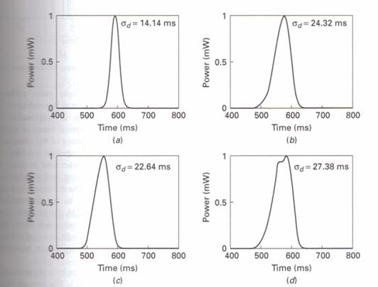
48 Multipath fading Different delays experienced by the different signal replicas (delay spread) can widen the channel impulse response leading to intersymbol interference (ISI Inter-Symbol Interference) 48

49 Examples 49

50 50 Examples
51 Impulse response 51
52 Multipath fading Impact of delay spread can be quantified by computing the root mean square (RMS Delay Spread): with τ d n 1 τ = τ n RMS i= 1 = n ( τ P ) i= 1 i P i i n i 1 P = i i= 1 ( 2 ) 2 P τ i i d τ RMS RMS delay spread τ i delay on path i P i power received on path i n number of paths 52
53 Multipath fading The coherence bandwidth, which is a statistical measurement of the bandwidth interval over which the channel is flat is approximated by the inverse of the delay spread If coherence bandwidth is >> signal bandwidth the channel is flat If coherence bandwidth is comparable to the signal bandwidth then delay spread results into intersymbol interference and reception errors In case of intersymbol interference equalization is used, introducing complexity. 53
Antennas & Propagation. CSG 250 Fall 2007 Rajmohan Rajaraman
 Antennas & Propagation CSG 250 Fall 2007 Rajmohan Rajaraman Introduction An antenna is an electrical conductor or system of conductors o Transmission - radiates electromagnetic energy into space o Reception
Antennas and Propagation. Chapter 5
 Antennas and Propagation Chapter 5 Introduction An antenna is an electrical conductor or system of conductors Transmission - radiates electromagnetic energy into space Reception - collects electromagnetic
Antennas and Propagation. Chapter 5
 Antennas and Propagation Chapter 5 Introduction An antenna is an electrical conductor or system of conductors Transmission - radiates electromagnetic energy into space Reception - collects electromagnetic
Antennas and Propagation
 Mobile Networks Module D-1 Antennas and Propagation 1. Introduction 2. Propagation modes 3. Line-of-sight transmission 4. Fading Slides adapted from Stallings, Wireless Communications & Networks, Second
Antennas and Propagation
 CMPE 477 Wireless and Mobile Networks Lecture 3: Antennas and Propagation Antennas Propagation Modes Line of Sight Transmission Fading in the Mobile Environment Introduction An antenna is an electrical
Antennas and Propagation
 Antennas and Propagation Chapter 5 Introduction An antenna is an electrical conductor or system of conductors Transmission - radiates electromagnetic energy into space Reception - collects electromagnetic
The Radio Channel. COS 463: Wireless Networks Lecture 14 Kyle Jamieson. [Parts adapted from I. Darwazeh, A. Goldsmith, T. Rappaport, P.
 The Radio Channel COS 463: Wireless Networks Lecture 14 Kyle Jamieson [Parts adapted from I. Darwazeh, A. Goldsmith, T. Rappaport, P. Steenkiste] Motivation The radio channel is what limits most radio
Session2 Antennas and Propagation
 Wireless Communication Presented by Dr. Mahmoud Daneshvar Session2 Antennas and Propagation 1. Introduction Types of Anttenas Free space Propagation 2. Propagation modes 3. Transmission Problems 4. Fading
CHAPTER 6 THE WIRELESS CHANNEL
 CHAPTER 6 THE WIRELESS CHANNEL These slides are made available to faculty in PowerPoint form. Slides can be freely added, modified, and deleted to suit student needs. They represent substantial work on
Vehicle Networks. Wireless communication basics. Univ.-Prof. Dr. Thomas Strang, Dipl.-Inform. Matthias Röckl
 Vehicle Networks Wireless communication basics Univ.-Prof. Dr. Thomas Strang, Dipl.-Inform. Matthias Röckl Outline Wireless Signal Propagation Electro-magnetic waves Signal impairments Attenuation Distortion
Radio Propagation Fundamentals
 Radio Propagation Fundamentals Concept of Electromagnetic Wave Propagation Mechanisms Modes of Propagation Propagation Models Path Profiles Link Budget Fading Channels Electromagnetic (EM) Waves EM Wave
Chapter 3. Mobile Radio Propagation
 Chapter 3 Mobile Radio Propagation Based on the slides of Dr. Dharma P. Agrawal, University of Cincinnati and Dr. Andrea Goldsmith, Stanford University Propagation Mechanisms Outline Radio Propagation
Mobile Communications
 Mobile Communications Part IV- Propagation Characteristics Professor Z Ghassemlooy School of Computing, Engineering and Information Sciences University of Northumbria U.K. http://soe.unn.ac.uk/ocr Contents
Project = An Adventure : Wireless Networks. Lecture 4: More Physical Layer. What is an Antenna? Outline. Page 1
 Project = An Adventure 18-759: Wireless Networks Checkpoint 2 Checkpoint 1 Lecture 4: More Physical Layer You are here Done! Peter Steenkiste Departments of Computer Science and Electrical and Computer
Propagation mechanisms
 RADIO SYSTEMS ETIN15 Lecture no: 2 Propagation mechanisms Ove Edfors, Department of Electrical and Information Technology Ove.Edfors@eit.lth.se Contents Short on db calculations Basics about antennas Propagation
Mobile and Wireless Networks Course Instructor: Dr. Safdar Ali
 Mobile and Wireless Networks Course Instructor: Dr. Safdar Ali BOOKS Text Book: William Stallings, Wireless Communications and Networks, Pearson Hall, 2002. BOOKS Reference Books: Sumit Kasera, Nishit
CS-435 spring semester Network Technology & Programming Laboratory. Stefanos Papadakis & Manolis Spanakis
 CS-435 spring semester 2016 Network Technology & Programming Laboratory University of Crete Computer Science Department Stefanos Papadakis & Manolis Spanakis CS-435 Lecture preview Wireless Networking
UNIT Derive the fundamental equation for free space propagation?
 UNIT 8 1. Derive the fundamental equation for free space propagation? Fundamental Equation for Free Space Propagation Consider the transmitter power (P t ) radiated uniformly in all the directions (isotropic),
Multi-Path Fading Channel
 Instructor: Prof. Dr. Noor M. Khan Department of Electronic Engineering, Muhammad Ali Jinnah University, Islamabad Campus, Islamabad, PAKISTAN Ph: +9 (51) 111-878787, Ext. 19 (Office), 186 (Lab) Fax: +9
Mobile Computing and the IoT Wireless and Mobile Computing. Wireless Signals. George Roussos.
 Mobile Computing and the IoT Wireless and Mobile Computing Wireless Signals George Roussos g.roussos@dcs.bbk.ac.uk Overview Signal characteristics Representing digital information with wireless Transmission
Channel. Muhammad Ali Jinnah University, Islamabad Campus, Pakistan. Multi-Path Fading. Dr. Noor M Khan EE, MAJU
 Instructor: Prof. Dr. Noor M. Khan Department of Electronic Engineering, Muhammad Ali Jinnah University, Islamabad Campus, Islamabad, PAKISTAN Ph: +9 (51) 111-878787, Ext. 19 (Office), 186 (Lab) Fax: +9
Antenna Basics. Antennas. A guide to effective antenna use
 A guide to effective antenna use Antennas Antennas transmit radio signals by converting radio frequency electrical currents into electromagnetic waves. Antennas receive the signals by converting the electromagnetic
Chapter 4 Radio Communication Basics
 Chapter 4 Radio Communication Basics Chapter 4 Radio Communication Basics RF Signal Propagation and Reception Basics and Keywords Transmitter Power and Receiver Sensitivity Power - antenna gain: G TX,
Revision of Lecture One
 Revision of Lecture One System blocks and basic concepts Multiple access, MIMO, space-time Transceiver Wireless Channel Signal/System: Bandpass (Passband) Baseband Baseband complex envelope Linear system:
Noise and Propagation mechanisms
 2 Noise and Propagation mechanisms Noise Johnson-Nyquist noise Physical review 1928 V rms2 = 4kTBR k : Bolzmann s constant T : absolute temperature B : bandwidth R : Resistance P=4kTB 1 1 Why is this a
LECTURE 3. Radio Propagation
 LECTURE 3 Radio Propagation 2 Simplified model of a digital communication system Source Source Encoder Channel Encoder Modulator Radio Channel Destination Source Decoder Channel Decoder Demod -ulator Components
Antenna Performance. Antenna Performance... 3 Gain... 4 Radio Power and the FCC... 6 Link Margin Calculations... 7 The Banner Way... 8 Glossary...
 Antenna Performance Antenna Performance... 3 Gain... 4 Radio Power and the FCC... 6 Link Margin Calculations... 7 The Banner Way... 8 Glossary... 9 06/15/07 135765 Introduction In this new age of wireless
6 Radio and RF. 6.1 Introduction. Wavelength (m) Frequency (Hz) Unit 6: RF and Antennas 1. Radio waves. X-rays. Microwaves. Light
 Frequency (Hz) Unit 6: RF and Antennas 1. Radio waves. X-rays. Microwaves. Light") 6 Radio and RF Ref: http://www.asecuritysite.com/wireless/wireless06 6.1 Introduction The electromagnetic (EM) spectrum contains a wide range of electromagnetic waves, from radio waves up to X-rays (as
6 Radio and RF Ref: http://www.asecuritysite.com/wireless/wireless06 6.1 Introduction The electromagnetic (EM) spectrum contains a wide range of electromagnetic waves, from radio waves up to X-rays (as
5.9 GHz V2X Modem Performance Challenges with Vehicle Integration
 5.9 GHz V2X Modem Performance Challenges with Vehicle Integration October 15th, 2014 Background V2V DSRC Why do the research? Based on 802.11p MAC PHY ad-hoc network topology at 5.9 GHz. Effective Isotropic
Antennas and Propagation. Chapter 6a: Propagation Definitions, Path-based Modeling
 Antennas and Propagation a: Propagation Definitions, Path-based Modeling Introduction Propagation How signals from antennas interact with environment Goal: model channel connecting TX and RX Antennas and
Antenna & Propagation. Basic Radio Wave Propagation
 For updated version, please click on http://ocw.ump.edu.my Antenna & Propagation Basic Radio Wave Propagation by Nor Hadzfizah Binti Mohd Radi Faculty of Electric & Electronics Engineering hadzfizah@ump.edu.my
EXAM QUESTION EXAMPLES
 EXAM QUESTION EXAMPLES ETIN10, CHANNEL MODELING FOR WIRELESS COMMUNICATIONS, 2017 Question 1 This question is regarding the concepts of large-scale and small-scale fading: a) Please give a brief physical
UNIK4230: Mobile Communications Spring 2013
 UNIK4230: Mobile Communications Spring 2013 Abul Kaosher abul.kaosher@nsn.com Mobile: 99 27 10 19 1 UNIK4230: Mobile Communications Propagation characteristis of wireless channel Date: 07.02.2013 2 UNIK4230:
White paper. Long range metering systems : VHF or UHF?
 ALCIOM 5, Parvis Robert Schuman 92370 CHAVILLE - FRANCE Tel/Fax : 01 47 09 30 51 contact@alciom.com www.alciom.com Project : White paper DOCUMENT : Long range metering systems : VHF or UHF? REFERENCE :
UNIT- 7. Frequencies above 30Mhz tend to travel in straight lines they are limited in their propagation by the curvature of the earth.
 UNIT- 7 Radio wave propagation and propagation models EM waves below 2Mhz tend to travel as ground waves, These wave tend to follow the curvature of the earth and lose strength rapidly as they travel away
Wireless Communication System
 Wireless Communication System Generic Block Diagram An t PC An r Source Tx Rx Destination P t G t L p G r P r Source a source of information to be transmitted Destination a destination of the transmitted
Channel Modeling and Characteristics
 Channel Modeling and Characteristics Dr. Farid Farahmand Updated:10/15/13, 10/20/14 Line-of-Sight Transmission (LOS) Impairments The received signal is different from the transmitted signal due to transmission
Wireless Channel Propagation Model Small-scale Fading
 Wireless Channel Propagation Model Small-scale Fading Basic Questions T x What will happen if the transmitter - changes transmit power? - changes frequency? - operates at higher speed? Transmit power,
Study of Factors which affect the Calculation of Co- Channel Interference in a Radio Link
 International Journal of Electronic and Electrical Engineering. ISSN 0974-2174 Volume 8, Number 2 (2015), pp. 103-111 International Research Publication House http://www.irphouse.com Study of Factors which
Channel Modelling ETIM10. Propagation mechanisms
 Channel Modelling ETIM10 Lecture no: 2 Propagation mechanisms Ghassan Dahman \ Fredrik Tufvesson Department of Electrical and Information Technology Lund University, Sweden 2012-01-20 Fredrik Tufvesson
Written Exam Channel Modeling for Wireless Communications - ETIN10
 Written Exam Channel Modeling for Wireless Communications - ETIN10 Department of Electrical and Information Technology Lund University 2017-03-13 2.00 PM - 7.00 PM A minimum of 30 out of 60 points are
Wireless Physical Layer Concepts: Part II
 Wireless Physical Layer Concepts: Part II Raj Jain Professor of CSE Washington University in Saint Louis Saint Louis, MO 63130 Jain@cse.wustl.edu Audio/Video recordings of this lecture are available at:
MSIT 413: Wireless Technologies Week 3
 MSIT 413: Wireless Technologies Week 3 Michael L. Honig Department of EECS Northwestern University January 2016 Why Study Radio Propagation? To determine coverage Can we use the same channels? Must determine
Revision of Lecture One
 Revision of Lecture One System block Transceiver Wireless Channel Signal / System: Bandpass (Passband) Baseband Baseband complex envelope Linear system: complex (baseband) channel impulse response Channel:
Small-Scale Fading I PROF. MICHAEL TSAI 2011/10/27
 Small-Scale Fading I PROF. MICHAEL TSAI 011/10/7 Multipath Propagation RX just sums up all Multi Path Component (MPC). Multipath Channel Impulse Response An example of the time-varying discrete-time impulse
Ad hoc and Sensor Networks Chapter 4: Physical layer. Holger Karl
 Ad hoc and Sensor Networks Chapter 4: Physical layer Holger Karl Goals of this chapter Get an understanding of the peculiarities of wireless communication Wireless channel as abstraction of these properties
Chapter 4. Propagation effects. Slides for Wireless Communications Edfors, Molisch, Tufvesson
 Chapter 4 Propagation effects Why channel modelling? The performance of a radio system is ultimately determined by the radio channel The channel models basis for system design algorithm design antenna
Outline / Wireless Networks and Applications Lecture 3: Physical Layer Signals, Modulation, Multiplexing. Cartoon View 1 A Wave of Energy
 Outline 18-452/18-750 Wireless Networks and Applications Lecture 3: Physical Layer Signals, Modulation, Multiplexing Peter Steenkiste Carnegie Mellon University Spring Semester 2017 http://www.cs.cmu.edu/~prs/wirelesss17/
Antennas and Propagation. Prelude to Chapter 4 Propagation
 Antennas and Propagation Prelude to Chapter 4 Propagation Introduction An antenna is an electrical conductor or system of conductors for: Transmission - radiates electromagnetic energy into space (involves
Noise and Interference Limited Systems
 Chapter 3 Noise and Interference Limited Systems 47 Basics of link budgets Link budgets show how different components and propagation processes influence the available SNR Link budgets can be used to compute
Development of a Wireless Communications Planning Tool for Optimizing Indoor Coverage Areas
 Development of a Wireless Communications Planning Tool for Optimizing Indoor Coverage Areas A. Dimitriou, T. Vasiliadis, G. Sergiadis Aristotle University of Thessaloniki, School of Engineering, Dept.
Review of Path Loss models in different environments
 Review of Path Loss models in different environments Mandeep Kaur 1, Deepak Sharma 2 1 Computer Scinece, Kurukshetra Institute of Technology and Management, Kurukshetra 2 H.O.D. of CSE Deptt. Abstract
Structure of the Lecture
 Structure of the Lecture Chapter 2 Technical Basics: Layer 1 Methods for Medium Access: Layer 2 Representation of digital signals on an analogous medium Signal propagation Characteristics of antennas Chapter
Unit 3 - Wireless Propagation and Cellular Concepts
 X Courses» Introduction to Wireless and Cellular Communications Unit 3 - Wireless Propagation and Cellular Concepts Course outline How to access the portal Assignment 2. Overview of Cellular Evolution
WIRELESS COMMUNICATIONS PRELIMINARIES
 WIRELESS COMMUNICATIONS Preliminaries Radio Environment Modulation Performance PRELIMINARIES db s and dbm s Frequency/Time Relationship Bandwidth, Symbol Rate, and Bit Rate 1 DECIBELS Relative signal strengths
EENG473 Mobile Communications Module 3 : Week # (12) Mobile Radio Propagation: Small-Scale Path Loss
 Mobile Radio Propagation: Small-Scale Path Loss") EENG473 Mobile Communications Module 3 : Week # (12) Mobile Radio Propagation: Small-Scale Path Loss Introduction Small-scale fading is used to describe the rapid fluctuation of the amplitude of a radio
EENG473 Mobile Communications Module 3 : Week # (12) Mobile Radio Propagation: Small-Scale Path Loss Introduction Small-scale fading is used to describe the rapid fluctuation of the amplitude of a radio
Planning a Microwave Radio Link
 8000 Lee Highway Falls Church, VA 22042 703-205-0600 www.ydi.com Planning a Microwave Radio Link By Michael F. Young President and CTO YDI Wireless Background Most installers know that clear line of sight
IN Wireless Sensor Networks. Koen Langendoen Muneeb Ali, Aline Baggio Gertjan Halkes
 IN4181 - Wireless Sensor Networks Koen Langendoen Muneeb Ali, Aline Baggio Gertjan Halkes VLSI Trends: Moore s Law in 1965, Gordon Moore predicted that transistors would continue to shrink, allowing: doubled
TSEK02: Radio Electronics Lecture 6: Propagation and Noise. Ted Johansson, EKS, ISY
 TSEK02: Radio Electronics Lecture 6: Propagation and Noise Ted Johansson, EKS, ISY 2 Propagation and Noise - Channel and antenna: not in the Razavi book - Noise: 2.3 The wireless channel The antenna Signal
Basic Propagation Theory
 S-7.333 POSTGRADUATE COURSE IN RADIO COMMUNICATIONS, AUTUMN 4 1 Basic Propagation Theory Fabio Belloni S-88 Signal Processing Laboratory, HUT fbelloni@hut.fi Abstract In this paper we provide an introduction
Probabilistic Link Properties. Octav Chipara
 Probabilistic Link Properties Octav Chipara Signal propagation Propagation in free space always like light (straight line) Receiving power proportional to 1/d² in vacuum much more in real environments
International Journal of Advance Engineering and Research Development
 Scientific Journal of Impact Factor (SJIF) : 3.134 ISSN (Print) : 2348-6406 ISSN (Online): 2348-4470 International Journal of Advance Engineering and Research Development COMPARATIVE ANALYSIS OF THREE
CHAPTER 2 WIRELESS CHANNEL
 CHAPTER 2 WIRELESS CHANNEL 2.1 INTRODUCTION In mobile radio channel there is certain fundamental limitation on the performance of wireless communication system. There are many obstructions between transmitter
Basic Radio Physics. Developed by Sebastian Buettrich. ItrainOnline MMTK 1
 Basic Radio Physics Developed by Sebastian Buettrich 1 Goals Understand radiation/waves used in wireless networking. Understand some basic principles of their behaviour. Apply this understanding to real
Mobile Radio Propagation Channel Models
 Wireless Information Transmission System Lab. Mobile Radio Propagation Channel Models Institute of Communications Engineering National Sun Yat-sen University Table of Contents Introduction Propagation
This Antenna Basics reference guide includes basic information about antenna types, how antennas work, gain, and some installation examples.
 Antenna Basics This Antenna Basics reference guide includes basic information about antenna types, how antennas work, gain, and some installation examples. What Do Antennas Do? Antennas transmit radio
Multipath fading effects on short range indoor RF links. White paper
 ALCIOM 5, Parvis Robert Schuman 92370 CHAVILLE - FRANCE Tel/Fax : 01 47 09 30 51 contact@alciom.com www.alciom.com Project : Multipath fading effects on short range indoor RF links DOCUMENT : REFERENCE
Industrial Wireless Systems
 Application Considerations Don Pretty Principal Engineer Geometric Controls Inc Bethlehem, PA Sheet 1 Ethernet Dominates on the Plant Floor Sheet 2 Recognize Any of These? Sheet 3 Answers: 10 BASE 2 RG
Path-loss and Shadowing (Large-scale Fading) PROF. MICHAEL TSAI 2015/03/27
 PROF. MICHAEL TSAI 2015/03/27") Path-loss and Shadowing (Large-scale Fading) PROF. MICHAEL TSAI 2015/03/27 Multipath 2 3 4 5 Friis Formula TX Antenna RX Antenna = 4 EIRP= Power spatial density 1 4 6 Antenna Aperture = 4 Antenna Aperture=Effective
Path-loss and Shadowing (Large-scale Fading) PROF. MICHAEL TSAI 2015/03/27 Multipath 2 3 4 5 Friis Formula TX Antenna RX Antenna = 4 EIRP= Power spatial density 1 4 6 Antenna Aperture = 4 Antenna Aperture=Effective
1.1 Introduction to the book
 1 Introduction 1.1 Introduction to the book Recent advances in wireless communication systems have increased the throughput over wireless channels and networks. At the same time, the reliability of wireless
Narrow- and wideband channels
 RADIO SYSTEMS ETIN15 Lecture no: 3 Narrow- and wideband channels Ove Edfors, Department of Electrical and Information technology Ove.Edfors@eit.lth.se 27 March 2017 1 Contents Short review NARROW-BAND
Übungen zu Drahtlose Kommunikation
 Übungen zu Drahtlose Kommunikation Wintersemester 2016/2017 Prof. Hannes Frey / Dr. Jovan Radak Assignment 1 voluntary submission until Wednesday 2016-11-23 as PDF via mail to vnuml@uni-koblenz.de Name
Chapter 4 The RF Link
 Chapter 4 The RF Link The fundamental elements of the communications satellite Radio Frequency (RF) or free space link are introduced. Basic transmission parameters, such as Antenna gain, Beamwidth, Free-space
Outline / Wireless Networks and Applications Lecture 5: Physical Layer Signal Propagation and Modulation
 Outline 18-452/18-750 Wireless Networks and Applications Lecture 5: Physical Layer Signal Propagation and Modulation Peter Steenkiste Carnegie Mellon University Spring Semester 2017 http://www.cs.cmu.edu/~prs/wirelesss17/
Ultra Wideband Radio Propagation Measurement, Characterization and Modeling
 Ultra Wideband Radio Propagation Measurement, Characterization and Modeling Rachid Saadane rachid.saadane@gmail.com GSCM LRIT April 14, 2007 achid Saadane rachid.saadane@gmail.com ( GSCM Ultra Wideband
Digital Communications over Fading Channel s
 over Fading Channel s Instructor: Prof. Dr. Noor M Khan Department of Electronic Engineering, Muhammad Ali Jinnah University, Islamabad Campus, Islamabad, PAKISTAN Ph: +9 (51) 111-878787, Ext. 19 (Office),
Experimental Evaluation Scheme of UWB Antenna Performance
 Tokyo Tech. Experimental Evaluation Scheme of UWB Antenna Performance Sathaporn PROMWONG Wataru HACHITANI Jun-ichi TAKADA TAKADA-Laboratory Mobile Communication Research Group Graduate School of Science
WIRELESS COMMUNICATION TECHNOLOGIES (16:332:546) LECTURE 5 SMALL SCALE FADING
 LECTURE 5 SMALL SCALE FADING") WIRELESS COMMUNICATION TECHNOLOGIES (16:332:546) LECTURE 5 SMALL SCALE FADING Instructor: Dr. Narayan Mandayam Slides: SabarishVivek Sarathy A QUICK RECAP Why is there poor signal reception in urban clutters?
WIRELESS COMMUNICATION TECHNOLOGIES (16:332:546) LECTURE 5 SMALL SCALE FADING Instructor: Dr. Narayan Mandayam Slides: SabarishVivek Sarathy A QUICK RECAP Why is there poor signal reception in urban clutters?
November 24, 2010xx. Introduction
 Path Analysis XXXXXXXXX Ref Number: XXXXXXX Introduction This report is an analysis of the proposed XXXXXXXXX network between XXXXXXX and XXXXXXX. The primary aim was to investigate the frequencies and
Topic 5: Radio wave propagation and safety issues
 6. Short-distance link design, Fresnel ellipsoide. Topic 5: Radio wave propagation and safety issues A 6. 10-km Short-distance link system, link see design, figures Fresnel 1) and 3) ellipsoide. below,
Muhammad Ali Jinnah University, Islamabad Campus, Pakistan. Fading Channel. Base Station
 Fading Lecturer: Assoc. Prof. Dr. Noor M Khan Department of Electronic Engineering, Muhammad Ali Jinnah University, Islamabad Campus, Islamabad, PAKISTAN Ph: +9 (51) 111-878787, Ext. 19 (Office), 186 (ARWiC
λ iso d 4 π watt (1) + L db (2)
 + L db (2)") 1 Path-loss Model for Broadcasting Applications and Outdoor Communication Systems in the VHF and UHF Bands Constantino Pérez-Vega, Member IEEE, and José M. Zamanillo Communications Engineering Department
1 Path-loss Model for Broadcasting Applications and Outdoor Communication Systems in the VHF and UHF Bands Constantino Pérez-Vega, Member IEEE, and José M. Zamanillo Communications Engineering Department
IEEE P Wireless Personal Area Networks
 IEEE P802.15 Wireless Personal Area Networks Project Title Date Submitted Source Re: IEEE P802.15 Working Group for Wireless Personal Area Networks (WPANs) Near Field Channel Model [27 October, 2004] [Hans
Empirical Path Loss Models
 Empirical Path Loss Models 1 Free space and direct plus reflected path loss 2 Hata model 3 Lee model 4 Other models 5 Examples Levis, Johnson, Teixeira (ESL/OSU) Radiowave Propagation August 17, 2018 1
TSEK02: Radio Electronics Lecture 6: Propagation and Noise. Ted Johansson, EKS, ISY
 TSEK02: Radio Electronics Lecture 6: Propagation and Noise Ted Johansson, EKS, ISY 2 Propagation and Noise - Channel and antenna: not in the Razavi book - Noise: 2.3 The wireless channel The antenna Signal
ECC Recommendation (16)04
04") ECC Recommendation (16)04 Determination of the radiated power from FM sound broadcasting stations through field strength measurements in the frequency band 87.5 to 108 MHz Approved 17 October 2016 Edition
ECC Recommendation (16)04 Determination of the radiated power from FM sound broadcasting stations through field strength measurements in the frequency band 87.5 to 108 MHz Approved 17 October 2016 Edition
5G Antenna Design & Network Planning
 5G Antenna Design & Network Planning Challenges for 5G 5G Service and Scenario Requirements Massive growth in mobile data demand (1000x capacity) Higher data rates per user (10x) Massive growth of connected
HY448 Sample Problems
 HY448 Sample Problems 10 November 2014 These sample problems include the material in the lectures and the guided lab exercises. 1 Part 1 1.1 Combining logarithmic quantities A carrier signal with power
Intro to Radio Propagation,Antennas and Link Budget
 Intro to Radio Propagation,Antennas and Link Budget Training materials for wireless trainers Marco Zennaro and Ermanno Pietrosemoli T/ICT4D Laboratory ICTP Behavior of radio waves There are a few simple
Unguided Transmission Media
 CS311 Data Communication Unguided Transmission Media by Dr. Manas Khatua Assistant Professor Dept. of CSE IIT Jodhpur E-mail: manaskhatua@iitj.ac.in Web: http://home.iitj.ac.in/~manaskhatua http://manaskhatua.github.io/
CS263: Wireless Communications and Sensor Networks
 CS263: Wireless Communications and Sensor Networks Matt Welsh Lecture 3: Antennas, Propagation, and Spread Spectrum September 30, 2004 2004 Matt Welsh Harvard University 1 Today's Lecture Antennas and
Adapted from Dr. Joe Montana (George mason University) Dr. James
 Dr. James") ink Budget Adapted from Dr. Joe Montana (George mason University) Dr. James W. apean course notes Dr. Jeremy Allnutt course notes And some internet resources + Tim Pratt book 1 ink Power Budget Tx EIRP
ink Budget Adapted from Dr. Joe Montana (George mason University) Dr. James W. apean course notes Dr. Jeremy Allnutt course notes And some internet resources + Tim Pratt book 1 ink Power Budget Tx EIRP
UWB Channel Modeling
 Channel Modeling ETIN10 Lecture no: 9 UWB Channel Modeling Fredrik Tufvesson & Johan Kåredal, Department of Electrical and Information Technology fredrik.tufvesson@eit.lth.se 2011-02-21 Fredrik Tufvesson
ECE 476/ECE 501C/CS Wireless Communication Systems Winter Lecture 6: Fading
 ECE 476/ECE 501C/CS 513 - Wireless Communication Systems Winter 2003 Lecture 6: Fading Last lecture: Large scale propagation properties of wireless systems - slowly varying properties that depend primarily
Wireless Networked Systems. Lec #1b: PHY Basics
 Wireless Networked Systems CS 795/895 - Spring 2013 Lec #1b: PHY Basics Tamer Nadeem Dept. of Computer Science Wireless Communication Page 2 Spring 2013 CS 795/895 - Wireless Networked Systems Radio Signal
Colubris Networks. Antenna Guide
 Colubris Networks Antenna Guide Creation Date: February 10, 2006 Revision: 1.0 Table of Contents 1. INTRODUCTION... 3 2. ANTENNA TYPES... 3 2.1. OMNI-DIRECTIONAL ANTENNA... 3 2.2. DIRECTIONAL ANTENNA...
Goal. A tutorial overview of wireless communication. Antennas, propagation and (de)modulation
modulation") Goal A tutorial overview of wireless communication Antennas, propagation and (de)modulation Focus on a single wireless link Operating on a small slice of spectrum called a channel, characterized by centre
Goal A tutorial overview of wireless communication Antennas, propagation and (de)modulation Focus on a single wireless link Operating on a small slice of spectrum called a channel, characterized by centre
Mm- Wave Propaga-on: Fundamentals and Models
 Mm- Wave Propaga-on: Fundamentals and Models Hajime Suzuki 7 April 2014 CSIRO Computa-onal Informa-cs CSIRO Radio Physics Laboratory Advanced Wireless Broadband Communica:ons in Rural Areas Page 2 Coded
Narrow- and wideband channels
 RADIO SYSTEMS ETIN15 Lecture no: 3 Narrow- and wideband channels Ove Edfors, Department of Electrical and Information technology Ove.Edfors@eit.lth.se 2012-03-19 Ove Edfors - ETIN15 1 Contents Short review
Module contents. Antenna systems. RF propagation. RF prop. 1
 Module contents Antenna systems RF propagation RF prop. 1 Basic antenna operation Dipole Antennas are specific to Frequency based on dimensions of elements 1/4 λ Dipole (Wire 1/4 of a Wavelength) creates