Dynamic Optical Adjustment of a PDV Signal in Real Time
|
|
|
- Meagan Stone
- 5 years ago
- Views:
Transcription
1 Dynamic Optical Adjustment of a PDV Signal in Real Time Heather Leffler Project Lead Design Team: Adam Iverson, Araceli Rutkowski, Wendi Dresen, Jason Young Sept 3, 2008 Page 1
2 Project Background Scope of Work: This project will develop a control system to dynamically adjust the optical power of a PDV signal in real time. Deliverable: A prototype PDV unit that adjusts the optical power in real time to stabilize the signal-to-noise ratio of the PDV time domain data. Benefits: Dynamic optical signal adjustment stabilizes the signal-tonoise ratio of the time domain data, yielding a more consistent signal-to-noise ratio in the frequency domain data. Page 2
3 Project Motivation To increase the amount of data returned by a PDV system fielded on a dynamic experiment. When the beat amplitude drops below the noise floor of the detector, we lose frequency data, i.e. particle velocity data. A PDV system that can dynamically maintain the return signal amplitude within set limits can be fielded with only one oscilloscope channel per probe saving the cost of a second oscilloscope ($60K to $120K). * *Added benefit Page 3

4 Current LAO PDV Detector Module Page 4
5 PDV System with Dynamic Optical Adjustment Page 5
6 Simplified PDV Signal Problem Page 6

7 Semiconductor Optical Amplifier (SOA) Provides 15 db of attenuation and 20 db of gain. Response time is quoted at <100 ps. Current controlled from 40 ma to 250 ma. Page 7
8 Proposed Solution SOA used for both Gain and Attenuation Page 8
9 Proposed PDV Signal Correction Page 9
10 The Approach Due to limited time and resources, decision to use only COTS evaluation boards no time for a custom PCB. Obtain an SOA and evaluate it. Modify it s evaluation driver board to try to get more speed out of it. Develop AGC circuits using COTS evaluation boards. Digital AGC Analog AGC Page 10
11 Digital AGC Used COTS FPGA evaluation board with on-board ADC and DAC. Available selection of COTS evaluation boards with ADC and DAC onboard are too generalized for our needs voltage levels are not a match, speeds not high enough. Chose the board that came closest to meeting our needs - Altera DSP Development Board, Statix II Edition with on-board 125 MSPS ADC and 165 MSPS DAC. Thoroughly characterized the board and proved that a digital solution could work given careful component selection, electrical interfacing, and ADC/DAC matching. Read a signal from the ADC into the FPGA using LVDS ran it through a ROM lookup table and output it to the DAC via LVDS -> 160 ns system latency using 100 MHz clocking. Page 11
12 Analog AGC Used two COTS Op Amp evaluation boards to create an inverting amplifier - drove the modified SOA evaluation board. Higher speed version - tens of us of response time with 10 db gain Slower speed - 1 or 2 ms with 16 db gain Page 12

13 Used tunable laser to simulate amplitude modulated beat signal Page 13
14 Page 14


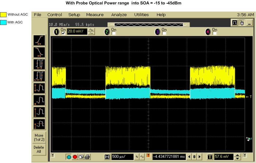
15 Dynamic Optical Adjustment of a PDV Signal in Real Time Lower speed version of AGC circuit. Simulated a probe return with an AM modulated wavelength that was shifted approx. 100MHz from the IPG wavelength Page 15
16 Green trace is normal PDV beat signal, Blue trace is AGC PDV beat signal Page 16


17 Dynamic Optical Adjustment of a PDV Signal in Real Time Normal PDV AGC PDV Page 17
18 Summary Demonstrated the ability to perform automatic gain control of a PDV signal in real time using an analog AGC circuit with 16 db of gain correction and a response time of a few milliseconds. Page 18
19 Summary (continued) Determined that digital solution requires custom PCB. A custom design of the SOA driver circuit would allow us to meet our target speed of 100 ns and would also improve its linearity, thus reducing the output signal variation. Terahertz Technologies Inc (TTI) optical detector not sensitive below -30 dbm. Considering an APD for next year such as the Newport AD50APDir. Weren t able to do a dynamic test due to time constraints and the slower speed of our AGC, thus all of our data so far is lab simulated. We are looking for funding in FY09 to develop a much faster field ready prototype to stabilize the signal to noise ratio as well as constrain the dynamic range. Page 19
Chapter 7: From Digital-to-Analog and Back Again
 Chapter 7: From Digital-to-Analog and Back Again Overview Often the information you want to capture in an experiment originates in the laboratory as an analog voltage or a current. Sometimes you want to
DSP Project. Reminder: Project proposal is due Friday, October 19, 2012 by 5pm in my office (Small 239).
.") DSP Project eminder: Project proposal is due Friday, October 19, 2012 by 5pm in my office (Small 239). Budget: $150 for project. Free parts: Surplus parts from previous year s project are available on
DSP Project eminder: Project proposal is due Friday, October 19, 2012 by 5pm in my office (Small 239). Budget: $150 for project. Free parts: Surplus parts from previous year s project are available on
Cenobio H. Gallegos (Sonny) Phone:
 Phone:") Cenobio H. Gallegos (Sonny) Phone: 505-663-2056 E-mail: gallegch@nv.doe.gov Approved for public release. Distribution unlimited. Page 1 DOE/NV/25946--829 Cenobio Gallegos, Matthew Teel, Bruce Marshall,
Cenobio H. Gallegos (Sonny) Phone: 505-663-2056 E-mail: gallegch@nv.doe.gov Approved for public release. Distribution unlimited. Page 1 DOE/NV/25946--829 Cenobio Gallegos, Matthew Teel, Bruce Marshall,
Direct Digital Down/Up Conversion for RF Control of Accelerating Cavities
 Direct Digital Down/Up Conversion for RF Control of Accelerating Cavities C. Hovater, T. Allison, R. Bachimanchi, J. Musson and T. Plawski Introduction As digital receiver technology has matured, direct
Testing with Femtosecond Pulses
 Testing with Femtosecond Pulses White Paper PN 200-0200-00 Revision 1.3 January 2009 Calmar Laser, Inc www.calmarlaser.com Overview Calmar s femtosecond laser sources are passively mode-locked fiber lasers.
Towards an ADC for the Liquid Argon Electronics Upgrade
 1 Towards an ADC for the Liquid Argon Electronics Upgrade Gustaaf Brooijmans Upgrade Workshop, November 10, 2009 2 Current LAr FEB Existing FEB (radiation tolerant for LHC, but slhc?) Limits L1 latency
LABORATORIES MAJOR EQUIPMENT IN THE LABORATORIES
 LABORATORIES Department is Equipped with the following Laboratories Electronic Devices Lab Electronic Circuits Analysis Lab Analog Communications/ Digital Communications Lab DECS Lab R & D Lab Microwave
Configuring the MAX3861 AGC Amp as an SFP Limiting Amplifier with RSSI
 Design Note: HFDN-22. Rev.1; 4/8 Configuring the MAX3861 AGC Amp as an SFP Limiting Amplifier with RSSI AVAILABLE Configuring the MAX3861 AGC Amp as an SFP Limiting Amplifier with RSSI 1 Introduction As
Digital Receiver Experiment or Reality. Harry Schultz AOC Aardvark Roost Conference Pretoria 13 November 2008
 Digital Receiver Experiment or Reality Harry Schultz AOC Aardvark Roost Conference Pretoria 13 November 2008 Contents Definition of a Digital Receiver. Advantages of using digital receiver techniques.
MODEL GB/S BROADBAND AMPLIFIER
 Electro-Absorption Modulator driver or optical receiver amplifier khz - 43 GHz bandwidth 8 ps risetime.7 V amp eye amplitude 8.5 db gain MODEL 5881 4 GB/S BROADBAND AMPLIFIER The 5881 is extremely broadband,
Measure the roll-off frequency of an acousto-optic modulator
 Slide 1 Goals of the Lab: Get to know some of the properties of pin photodiodes Measure the roll-off frequency of an acousto-optic modulator Measure the cut-off frequency of a pin photodiode as a function
ADI 2006 RF Seminar. Chapter II RF/IF Components and Specifications for Receivers
 ADI 2006 RF Seminar Chapter II RF/IF Components and Specifications for Receivers 1 RF/IF Components and Specifications for Receivers Fixed Gain and Variable Gain Amplifiers IQ Demodulators Analog-to-Digital
Accurate Harmonics Measurement by Sampler Part 2
 Accurate Harmonics Measurement by Sampler Part 2 Akinori Maeda Verigy Japan akinori.maeda@verigy.com September 2011 Abstract of Part 1 The Total Harmonic Distortion (THD) is one of the major frequency
New Focus High Speed Photoreceivers
 New Focus High Speed 1 About New Focus Products Newport s New Focus products are among our most innovative, high-performance, high-quality, and easy-to-use photonics tools and equipment. They include exceptional
Understanding RF and Microwave Analysis Basics
 Understanding RF and Microwave Analysis Basics Kimberly Cassacia Product Line Brand Manager Keysight Technologies Agenda µw Analysis Basics Page 2 RF Signal Analyzer Overview & Basic Settings Overview
Designing for Femtosecond Pulses
 Designing for Femtosecond Pulses White Paper PN 200-1100-00 Revision 1.1 July 2013 Calmar Laser, Inc www.calmarlaser.com Overview Calmar s femtosecond laser sources are passively mode-locked fiber lasers.
9 Feedback and Control
 9 Feedback and Control Due date: Tuesday, October 20 (midnight) Reading: none An important application of analog electronics, particularly in physics research, is the servomechanical control system. Here
Design of the Front-End Readout Electronics for ATLAS Tile Calorimeter at the slhc
 IEEE TRANSACTIONS ON NUCLEAR SCIENCE, VOL. 60, NO. 2, APRIL 2013 1255 Design of the Front-End Readout Electronics for ATLAS Tile Calorimeter at the slhc F. Tang, Member, IEEE, K. Anderson, G. Drake, J.-F.
Effects of Intensity and Position Modulation On Switched Electrode Electronics Beam Position Monitor Systems at Jefferson Lab*
 JLAB-ACT--9 Effects of Intensity and Position Modulation On Switched Electrode Electronics Beam Position Monitor Systems at Jefferson Lab* Tom Powers Thomas Jefferson National Accelerator Facility Newport
Dr. Steve Morra, DE, PE.
 PDV Fringe Recorder Development Dr. Steve Morra, DE, PE Third Millennium Engineering Plano, Texas USA Motive Agenda Interferometry t approximation for PDV High-Speed PDV systems and costs PDV Fringe Counter
Measuring Photonic, Optoelectronic and Electro optic S parameters using an advanced photonic module
 Measuring Photonic, Optoelectronic and Electro optic S parameters using an advanced photonic module APPLICATION NOTE This application note describes the procedure for electro-optic measurements of both
OpenAFM. Electronics
 OpenAFM Electronics Voice Coils Each coil is controlled by a pair of push-pull amplifiers. One of each pair has a constant output voltage of 2.5v The other member of the pair is controlled by the output
Simultaneous Co-Test of High Performance DAC-ADC Pairs May 13-28
 Simultaneous Co-Test of High Performance DAC-ADC Pairs Adviser & Client Members Luke Goetzke Ben Magstadt Tao Chen Aug, 2012 May, 2013 1 Agenda Project Description Project Design Test and Debug Results
INGAAS FAST PIN (RF) AMPLIFIED PHOTODETECTORS
 AMPLIFIED PHOTODETECTORS") INGAAS FAST PIN (RF) AMPLIFIED PHOTODETECTORS High Signal-to-Noise Ratio Ultrafast up to 9.5 GHz Free-Space or Fiber-Coupled InGaAs Photodetectors Wavelength Range from 750-1650 nm FPD310 FPD510-F https://www.thorlabs.com/newgrouppage9_pf.cfm?guide=10&category_id=77&objectgroup_id=6687
INGAAS FAST PIN (RF) AMPLIFIED PHOTODETECTORS High Signal-to-Noise Ratio Ultrafast up to 9.5 GHz Free-Space or Fiber-Coupled InGaAs Photodetectors Wavelength Range from 750-1650 nm FPD310 FPD510-F https://www.thorlabs.com/newgrouppage9_pf.cfm?guide=10&category_id=77&objectgroup_id=6687
OBJECTIVES EQUIPMENT LIST
 1 Reception of Amplitude Modulated Signals AM Demodulation OBJECTIVES The purpose of this experiment is to show how the amplitude-modulated signals are demodulated to obtain the original signal. Also,
ISMRM weekend educational course, MR Systems Engineering, Console Electronics
 ISMRM weekend educational course, MR Systems Engineering, Console Electronics. 2013-4-20 Declaration of Relevant Financial Interests or Relationships Speaker Name: Katsumi Kose, Ph.D. I have the following
In-Flight Performance Analysis of Direct RF Sampling Architecture Applied to VHF Band Avionics
 In-Flight Performance Analysis of Direct RF Sampling Architecture Applied to VHF Band Avionics A. Q. Nguyen, A. Amrhar, A. A. Kisomi, X. Fang, R Jr. Landry IEEE Aeroconf 2018 4 th March, 2018 Session 4.13
SiTime University Turbo Seminar Series
 SiTime University Turbo Seminar Series How to Measure Clock Jitter Part I Principle and Practice April 8-9, 2013 Agenda Jitter definitions and terminology Who cares about jitter How to measure clock jitter
Nonlinear Dynamical Behavior in a Semiconductor Laser System Subject to Delayed Optoelectronic Feedback
 Nonlinear Dynamical Behavior in a Semiconductor Laser System Subject to Delayed Optoelectronic Feedback Final Report: Robert E. Lee Summer Research 2000 Steven Klotz and Nick Silverman Faculty Adviser:
GS7000 and GainMaker Reverse Segmentable Node bdr Digital Reverse 2:1 Multiplexing System
 GS7000 and GainMaker Reverse Segmentable Node bdr Digital Reverse 2:1 Multiplexing System The bdr Digital Reverse 2:1 Multiplexing System expands the functionality of the GS7000 and GainMaker Reverse Segmentable
Keysight Technologies Gustaaf Sutorius
 1 1 mmw Seminar 2017 Keysight Technologies 18-04-2018 Gustaaf Sutorius Introduction & Agenda Why mmwave Industry needs & mmwave challenges Generating mmwave Analyzing mmwave Characterizing mmwave components
for amateur radio applications and beyond...
 for amateur radio applications and beyond... Table of contents Numerically Controlled Oscillator (NCO) Basic implementation Optimization for reduced ROM table sizes Achievable performance with FPGA implementations
The Theta Laser A Low Noise Chirped Pulse Laser. Dimitrios Mandridis
 CREOL Affiliates Day 2011 The Theta Laser A Low Noise Chirped Pulse Laser Dimitrios Mandridis dmandrid@creol.ucf.edu April 29, 2011 Objective: Frequency Swept (FM) Mode-locked Laser Develop a frequency
Implementation of All-Optical Logic AND Gate using XGM based on Semiconductor Optical Amplifiers
 Implementation of All-Optical Logic AND Gate using XGM based on Semiconductor Optical Amplifiers Sang H. Kim 1, J. H. Kim 1,2, C. W. Son 1, G. Kim 1, Y. T. yun 1, Y. M. Jhon 1, S. Lee 1, D. H. Woo 1, and
Ultrasound Brain Imaging System
 Ultrasound Brain Imaging System Dec13-01 Michael McFarland Zach Bertram Jonathan Runchey Maurio Mckay Client/Advisor: Dr. Timothy Bigelow 1 Table of Contents Problem Statement 3 System Block Diagram 3
DIFFERENTIAL ABSORPTION LIDAR FOR GREENHOUSE GAS MEASUREMENTS
 DIFFERENTIAL ABSORPTION LIDAR FOR GREENHOUSE GAS MEASUREMENTS Stephen E. Maxwell, Sensor Science Division, PML Kevin O. Douglass, David F. Plusquellic, Radiation and Biomolecular Physics Division, PML
Measuring of small AC signals using lock-in amplifiers. Narrow band selective amplifiers + amplitude detector. Lock-in amplifiers
 Measuring of small AC signals using lock-in amplifiers. Narrow band selective amplifiers + amplitude detector. Lock-in amplifiers 3/12/2013 Physics 403 Spring 2013 1 Simplified block diagram of a lock-in
Optoelectronic Components Testing with a VNA(Vector Network Analyzer) VNA Roadshow Budapest 17/05/2016
 VNA Roadshow Budapest 17/05/2016") Optoelectronic Components Testing with a VNA(Vector Network Analyzer) VNA Roadshow Budapest 17/05/2016 Content Introduction Photonics & Optoelectronics components Optical Measurements VNA (Vector Network
Optoelectronic Components Testing with a VNA(Vector Network Analyzer) VNA Roadshow Budapest 17/05/2016 Content Introduction Photonics & Optoelectronics components Optical Measurements VNA (Vector Network
EDFA Applications in Test & Measurement
 EDFA Applications in Test & Measurement White Paper PN 200-0600-00 Revision 1.1 September 2003 Calmar Optcom, Inc www.calamropt.com Overview Erbium doped fiber amplifiers (EDFAs) amplify optical pulses
Building a reliable magnetic card reader (Part 1 of 2)
") Building a reliable magnetic card reader (Part 1 of 2) Dan Sweet, Applications Engineer, Cypress Semiconductor Corp. 6/14/2010 6:30 AM EDT Dan Sweet, Applications Engineer, Cypress Semiconductor Corp.
Building a reliable magnetic card reader (Part 1 of 2) Dan Sweet, Applications Engineer, Cypress Semiconductor Corp. 6/14/2010 6:30 AM EDT Dan Sweet, Applications Engineer, Cypress Semiconductor Corp.
Using High Speed Differential Amplifiers to Drive Analog to Digital Converters
 Using High Speed Differential Amplifiers to Drive Analog to Digital Converters Selecting The Best Differential Amplifier To Drive An Analog To Digital Converter The right high speed differential amplifier
Computer Networks. Practice Set I. Dr. Hussein Al-Bahadili
 بسم االله الرحمن الرحيم Computer Networks Practice Set I Dr. Hussein Al-Bahadili (1/11) Q. Circle the right answer. 1. Before data can be transmitted, they must be transformed to. (a) Periodic signals
FlexDDS-NG DUAL. Dual-Channel 400 MHz Agile Waveform Generator
 FlexDDS-NG DUAL Dual-Channel 400 MHz Agile Waveform Generator Excellent signal quality Rapid parameter changes Phase-continuous sweeps High speed analog modulation Wieserlabs UG www.wieserlabs.com FlexDDS-NG
PB T/R Two-Channel Portable Frequency Domain Terahertz Spectrometer
 Compact, Portable Terahertz Spectroscopy System Bakman Technologies versatile PB7220-2000-T/R Spectroscopy Platform is designed for scanning complex compounds to precise specifications with greater accuracy
Characterizing High-Speed Oscilloscope Distortion A comparison of Agilent and Tektronix high-speed, real-time oscilloscopes
 Characterizing High-Speed Oscilloscope Distortion A comparison of Agilent and Tektronix high-speed, real-time oscilloscopes Application Note 1493 Table of Contents Introduction........................
FMC ADC 125M 14b 1ch DAC 600M 14b 1ch Technical Specification
 FMC ADC 125M 14b 1ch DAC 600M 14b 1ch Technical Specification Tony Rohlev October 5, 2011 Abstract The FMC ADC 125M 14b 1ch DAC 600M 14b 1ch is a FMC form factor card with a single ADC input and a single
EUROFEL-Report-2006-DS EUROPEAN FEL Design Study
 EUROFEL-Report-2006-DS3-034 EUROPEAN FEL Design Study Deliverable N : D 3.8 Deliverable Title: RF Amplitude and Phase Detector Task: Author: DS-3 F.Ludwig, M.Hoffmann, M.Felber, Contract N : 011935 P.Strzalkowski,
Model 305 Synchronous Countdown System
 Model 305 Synchronous Countdown System Introduction: The Model 305 pre-settable countdown electronics is a high-speed synchronous divider that generates an electronic trigger pulse, locked in time with
Simulation of Algorithms for Pulse Timing in FPGAs
 2007 IEEE Nuclear Science Symposium Conference Record M13-369 Simulation of Algorithms for Pulse Timing in FPGAs Michael D. Haselman, Member IEEE, Scott Hauck, Senior Member IEEE, Thomas K. Lewellen, Senior
FLASH rf gun. beam generated within the (1.3 GHz) RF gun by a laser. filling time: typical 55 μs. flat top time: up to 800 μs
 RF gun by a laser. filling time: typical 55 μs. flat top time: up to 800 μs") The gun RF control at FLASH (and PITZ) Elmar Vogel in collaboration with Waldemar Koprek and Piotr Pucyk th FLASH Seminar at December 19 2006 FLASH rf gun beam generated within the (1.3 GHz) RF gun by
The gun RF control at FLASH (and PITZ) Elmar Vogel in collaboration with Waldemar Koprek and Piotr Pucyk th FLASH Seminar at December 19 2006 FLASH rf gun beam generated within the (1.3 GHz) RF gun by
Design and performance of LLRF system for CSNS/RCS *
 Design and performance of LLRF system for CSNS/RCS * LI Xiao 1) SUN Hong LONG Wei ZHAO Fa-Cheng ZHANG Chun-Lin Institute of High Energy Physics, Chinese Academy of Sciences, Beijing 100049, China Abstract:
Power Amplifier Linearization using RF Pre-Distortion JUNE, 2012
 Power Amplifier Linearization using RF Pre-Distortion JUNE, 2012 1 PA Linearization Overview General principles Overview/Block Diagram of DPD and RFPD RFPAL System architecture & Implementation Predistortion
APPLICATION NOTE 3942 Optimize the Buffer Amplifier/ADC Connection
 Maxim > Design Support > Technical Documents > Application Notes > Communications Circuits > APP 3942 Maxim > Design Support > Technical Documents > Application Notes > High-Speed Interconnect > APP 3942
PURPOSE: NOTE: Be sure to record ALL results in your laboratory notebook.
 EE4902 Lab 9 CMOS OP-AMP PURPOSE: The purpose of this lab is to measure the closed-loop performance of an op-amp designed from individual MOSFETs. This op-amp, shown in Fig. 9-1, combines all of the major
Specifications and Interfaces
 Specifications and Interfaces Crimson TNG is a wide band, high gain, direct conversion quadrature transceiver and signal processing platform. Using analogue and digital conversion, it is capable of processing
Fundamentals of Data Converters. DAVID KRESS Director of Technical Marketing
 Fundamentals of Data Converters DAVID KRESS Director of Technical Marketing 9/14/2016 Analog to Electronic Signal Processing Sensor (INPUT) Amp Converter Digital Processor Actuator (OUTPUT) Amp Converter
EE 435 Switched Capacitor Amplifiers and Filters. Lab 7 Spring 2014 R 2 V OUT V IN. (a) (b)
 (b)") EE 435 Switched Capacitor Amplifiers and Filters Lab 7 Spring 2014 Amplifiers are widely used in many analog and mixed-signal applications. In most discrete applications resistors are used to form the
EE 435 Switched Capacitor Amplifiers and Filters Lab 7 Spring 2014 Amplifiers are widely used in many analog and mixed-signal applications. In most discrete applications resistors are used to form the
Lab Exercise PN: Phase Noise Measurement - 1 -
 Lab Exercise PN: Phase Noise Measurements Phase noise is a critical specification for oscillators used in applications such as Doppler radar and synchronous communications systems. It is tricky to measure
Model 6944 and 6940 Node bdr Digital Reverse 4:1 Multiplexing System designed for Prisma II Platform
 Optoelectronics Model 6944 and 6940 Node bdr Digital Reverse 4:1 Multiplexing System designed for Prisma II Platform Description The bdr Digital Reverse 4:1 Multiplexing System expands the functionality
Dual-channel Lock-in Amplifier Module
 Dual-channel Lock-in Amplifier Module Introduction Phase-locked amplification and demodulation techniques of weak signals have a wide range of applications in Turnable Diode Laser Absorption Spectrum (TDLAS)
Week 8 AM Modulation and the AM Receiver
 Week 8 AM Modulation and the AM Receiver The concept of modulation and radio transmission is introduced. An AM receiver is studied and the constructed on the prototyping board. The operation of the AM
10 Mb/s Single Twisted Pair Ethernet 10BASE-T1L PSD Mask Steffen Graber Pepperl+Fuchs
 10 Mb/s Single Twisted Pair Ethernet 10BASE-T1L PSD Mask Steffen Graber Pepperl+Fuchs IEEE P802.3cg 10 Mb/s Single Twisted Pair Ethernet Task Force 1/15/2018 1 Content Time Domain Specification Time Domain
Optical Delay Line Application Note
 1 Optical Delay Line Application Note 1.1 General Optical delay lines system (ODL), incorporates a high performance lasers such as DFBs, optical modulators for high operation frequencies, photodiodes,
Design Document. Analog PWM Amplifier. Reference: DD00004
 Grainger Center for Electric Machinery and Electromechanics Department of Electrical and Computer Engineering University of Illinois at Urbana-Champaign 1406 W. Green St. Urbana, IL 61801 Design Document
Sweep / Function Generator User Guide
 I. Overview Sweep / Function Generator User Guide The Sweep/Function Generator as developed by L. J. Haskell was designed and built as a multi-functional test device to help radio hobbyists align antique
Wireless Power and Data Acquisition System for Large Detectors
 Wireless Power and Data Acquisition System for Large Detectors Himansu Sahoo, Patrick De Lurgio, Zelimir Djurcic, Gary Drake, Andrew Kreps High Energy Physics Division 5th Annual Postdoctoral Research
EE 230. Electronic Circuits and Systems. Randy Geiger 2133 Coover
 EE 230 Electronic Circuits and Systems Randy Geiger 2133 Coover rlgeiger@iastate.edu 294-7745 Course Description Linear Systems Frequency domain characterization of electronic circuits and systems transfer
RF System: Baseband Application Note
 Jimmy Hua 997227433 EEC 134A/B RF System: Baseband Application Note Baseband Design and Implementation: The purpose of this app note is to detail the design of the baseband circuit and its PCB implementation
Hideo Okawara s Mixed Signal Lecture Series. DSP-Based Testing Fundamentals 37 F-matrix Simulation TDR
 Hideo Okawara s Mixed Signal Lecture Series DSP-Based Testing Fundamentals 37 F-matrix Simulation TDR Verigy Japan June 2011 Preface to the Series ADC and DAC are the most typical mixed signal devices.
ModBox Pulse 100 ps - ms Optical Pulse Transmitter
 Delivering Modulation Solutions Cybel, LLC. North American Distributor Pulse The -Pulse is an optical modulation unit that generates high performance optical pulses. The equipment incorporates a modulation
DEFINITIONS AND FUNDAMENTAL PRINCIPLES IDC
 DEFINITIONS AND FUNDAMENTAL PRINCIPLES Data Communications Information is transmitted between two points in the form of data. Analog» Varying amplitude, phase and frequency Digital» In copper systems represented
SAMPULSE50GHz and SAMPULSE70GHzANT PULSER/SAMPLER DEMO BOARD
 SAMPULSE50GHz and SAMPULSE70GHzANT PULSER/SAMPLER DEMO BOARD REV B. PRELIMINARY USER MANUAL 2/25/15 Figure 1. Connections to SAMPULSE50GHz (left) or SAMPULSE70GHzANT (right). INTRODUCTION: The SAMPULSE50GHz
Analog and Telecommunication Electronics
 Politecnico di Torino - ICT School Analog and Telecommunication Electronics E1 - Filters type and design» Filter taxonomy and parameters» Design flow and tools» FilterCAD example» Basic II order cells
Application Note. Photonic Doppler Velocimetry
 Application Note Photonic Doppler Velocimetry The velocity measurement of fast-moving materials is essential to several areas of scientific and technical investigations, including shock physics and the
Agilent 81980/ 81940A, Agilent 81989/ 81949A, Agilent 81944A Compact Tunable Laser Sources
 Agilent 81980/ 81940A, Agilent 81989/ 81949A, Agilent 81944A Compact Tunable Laser Sources December 2004 Agilent s Series 819xxA high-power compact tunable lasers enable optical device characterization
레이저의주파수안정화방법및그응용 박상언 ( 한국표준과학연구원, 길이시간센터 )
") 레이저의주파수안정화방법및그응용 박상언 ( 한국표준과학연구원, 길이시간센터 ) Contents Frequency references Frequency locking methods Basic principle of loop filter Example of lock box circuits Quantifying frequency stability Applications
레이저의주파수안정화방법및그응용 박상언 ( 한국표준과학연구원, 길이시간센터 ) Contents Frequency references Frequency locking methods Basic principle of loop filter Example of lock box circuits Quantifying frequency stability Applications
Lecture 12 Building Components
 Optical Fibres and Telecommunications Lecture 12 Building Components Introduction Where are we? Turning individual elements into components Transmitters Receivers Modulation formats Repeaters and 3-R Regeneration
Digitally-Controlled RF Self- Interference Canceller for Full-Duplex Radios
 Digitally-Controlled RF Self- nterference Canceller for Full-Duplex Radios Joose Tamminen 1, Matias Turunen 1, Dani Korpi 1, Timo Huusari 2, Yang-Seok Choi 2, Shilpa Talwar 2, and Mikko Valkama 1 1 Dept.
Chapter IX Using Calibration and Temperature Compensation to improve RF Power Detector Accuracy By Carlos Calvo and Anthony Mazzei
 Chapter IX Using Calibration and Temperature Compensation to improve RF Power Detector Accuracy By Carlos Calvo and Anthony Mazzei Introduction Accurate RF power management is a critical issue in modern
Design and Fabrication of a Microheater Control System. Mike Chambers
 Design and Fabrication of a Microheater Control System Mike Chambers Senior Project Mentor: Florian Solzbacher, PhD Senior Project Advisor: Ken Stevens, PhD Correspondence to: mike.chambers@utah.edu Project
Optical to Electrical Converter
 Optical to Electrical Converter By Dietrich Reimer Senior Project ELECTRICAL ENGINEERING DEPARTMENT California Polytechnic State University San Luis Obispo 2010 1 Table of Contents List of Tables and Figures...
Analog and Telecommunication Electronics
 Politecnico di Torino - ICT School Analog and Telecommunication Electronics E1 - Filters type and design» Filter taxonomy and parameters» Design flow and tools» FilterCAD example» Basic II order cells
A New Look at SDR Testing
 A New Look at SDR Testing (presented at SDR Academy 2016, Friedrichshafen, Germany) Adam Farson VA7OJ/AB4OJ Copyright 2016 A. Farson VA7OJ/AB4OJ 25-Dec-17 SDR Academy 2016 - SDR Testing 1 Performance issues
Lab 4: Analysis of the Stereo Amplifier
 ECE 212 Spring 2010 Circuit Analysis II Names: Lab 4: Analysis of the Stereo Amplifier Objectives In this lab exercise you will use the power supply to power the stereo amplifier built in the previous
When you have completed this exercise, you will be able to relate the gain and bandwidth of an op amp
 Op Amp Fundamentals When you have completed this exercise, you will be able to relate the gain and bandwidth of an op amp In general, the parameters are interactive. However, in this unit, circuit input
Using the Peak Detector Voltage to Compensate Output Voltage Change over Temperature
 Using the Peak Detector Voltage to Compensate Output Voltage Change over Temperature This document explains how to use the driver amplifier s peak detector to compensate the amplifier s output voltage
University of Pennsylvania. Department of Electrical and Systems Engineering. ESE Undergraduate Laboratory. Analog to Digital Converter
 University of Pennsylvania Department of Electrical and Systems Engineering ESE Undergraduate Laboratory Analog to Digital Converter PURPOSE The purpose of this lab is to design and build a simple Digital-to-Analog
Keywords: comparator, operation amplifier, detector. 1. Introduction. 2. Theory
 Design Optical Comparator Prototype for Interferometery Wail Yas Nassir Department of Laser and Optoelectronics Engineering, University of Technology Baghdad, Iraq Abstract The objective of this research
MaxxBass Development Recommendations
 MaxxBass Development Recommendations 1 Purpose The document provides recommendations on MaxxBass in evaluation, selection of possible implementations, circuit design and testing. It also refers to several
Optical Digital Transmission Systems. Xavier Fernando ADROIT Lab Ryerson University
 Optical Digital Transmission Systems Xavier Fernando ADROIT Lab Ryerson University Overview In this section we cover point-to-point digital transmission link design issues (Ch8): Link power budget calculations
MICROPROCESSOR LAB DETAILS
 ECE LAB - VIEW MICROPROCESSOR LAB DETAILS S.No Name of The Item Quantity Total Cost 1 8085 Microprocessor Trainer Kit 5 26,985 2 8086 Microprocessor Kit 5 30,200 3 8086 Microprocessor Trainer Kit (LED)
Keysight Technologies
 Keysight Technologies Generating Signals Basic CW signal Block diagram Applications Analog Modulation Types of analog modulation Block diagram Applications Digital Modulation Overview of IQ modulation
SPECIFICATIONS. Tunable Single-Frequency Laser Box. DL-BF12-CLSwwwB-Sxxxx-yy-zz
 DENSELIGHT SEMICONDUCTORS PTE. LTD. 6 Changi North St. 2, S498831 SINGAPORE Tel: (65) 64154488 Fax: (65) 64157988 www.denselight.com SPECIFICATIONS Tunable Single-Frequency Laser Box DenseLight Semiconductors
Why/When I need a Spectrum Analyzer. Jan 12, 2017
 Why/When I need a Jan 12, 2017 Common Questions What s the difference of Oscilloscope and Spectrum Analysis Almost all Oscilloscope has FFT for a spectrum view, why I need a spectrum analyzer? When shall
Lecture Fundamentals of Data and signals
 IT-5301-3 Data Communications and Computer Networks Lecture 05-07 Fundamentals of Data and signals Lecture 05 - Roadmap Analog and Digital Data Analog Signals, Digital Signals Periodic and Aperiodic Signals
EE320L Electronics I. Laboratory. Laboratory Exercise #2. Basic Op-Amp Circuits. Angsuman Roy. Department of Electrical and Computer Engineering
 EE320L Electronics I Laboratory Laboratory Exercise #2 Basic Op-Amp Circuits By Angsuman Roy Department of Electrical and Computer Engineering University of Nevada, Las Vegas Objective: The purpose of
TAKE THE MYSTERY OUT OF PROBING. 7 Common Oscilloscope Probing Pitfalls to Avoid
 TAKE THE MYSTERY OUT OF PROBING 7 Common Oscilloscope Probing Pitfalls to Avoid Introduction Understanding common probing pitfalls and how to avoid them is crucial in making better measurements. In an
11.1 Gbit/s Pluggable Small Form Factor DWDM Optical Transceiver Module
 INFORMATION & COMMUNICATIONS 11.1 Gbit/s Pluggable Small Form Factor DWDM Transceiver Module Yoji SHIMADA*, Shingo INOUE, Shimako ANZAI, Hiroshi KAWAMURA, Shogo AMARI and Kenji OTOBE We have developed
MEASURING HUM MODULATION USING MATRIX MODEL HD-500 HUM DEMODULATOR
 MEASURING HUM MODULATION USING MATRIX MODEL HD-500 HUM DEMODULATOR The SCTE defines hum modulation as, The amplitude distortion of a signal caused by the modulation of the signal by components of the power
Mike Harrop September PMD Testing in modern networks
 Mike Harrop Mike.harrop@exfo.com September 2016 PMD Testing in modern networks Table of Contents 1 Quick review of PMD 2 Impacts & limits 3 Impact of coherent systems 4 Challenges/Reducing the risk 5 Solutions