CAUTION. - The product is a changed speed operation device which is used to control three-phase induction motor.
|
|
|
- Coral Dawson
- 5 years ago
- Views:
Transcription

1 Instruction Manual New simple Inverter CAUTION Thanks you for purchasing our FVR-Micro series of inverters. - The product is a changed speed operation device which is used to control three-phase induction motor. Before use it, please read and understand items under the service manual so as to ensure correct use of it. - Incorrect use will hinder it from normal operation, or causes failure and reduce its service life. - Please make sure to deliver the service manual to the end-user. - The service manual shall be kept until the inverter is scrapped. - As for the use methods of equipment not covered in the service manual, please refer to the instruction manual of corresponding equipment for details. Fuji Electric Co., Ltd INR-S E
2 Fuji Electric Co., Ltd All rights reserved. The copyright of the service manual is owned by Fuji Electric Co., Ltd The company names and product names in the manual are the trademark and registered trademark of the companies. The manual is subject to change without notice.
3 Contents PREFACE... 4 Ⅰ. SAFETY INSTRUCTIONS NOTES FOR OPERATION NOTES FOR OPERATION ENVIRONMENT... 6 Ⅱ. DESCRIPTIONS FOR BODY AND INSTALLATION OPERATION ENVIRONMENT MODEL DESCRIPTION PRODUCT SPECIFICATIONS LIST OF APPLICABLE NO-FUSE BREAKER APPLICATION AND DESCRIPTION FOR AMBIENT EQUIPMENTS BASIC WIRING DIAGRAM EXTERNAL DIMENSIONS Ⅲ. DESCRIPTION OF OPERATION PANEL DESCRIPTION FOR DIGITAL OPERATION PANEL DESCRIPTION OF PANELOPERATION PRELIMINARY OPERATION-NOT CONNECTING WITH MOTOR Ⅳ. LIST OF DESCRIPTIONS FOR FUNCTIONAL PARAMETERS Ⅴ. DESCRIPTION OF FUNCTIONAL PARAMETERS USER'S PARAMETERS BASIC PARAMETERS OPERATION MODE PARAMETERS OUTPUT FUNCTION PARAMETERS INPUT FUNCTION PARAMETERS MULTI-STEP AND AUTO-PROGRAM OPERATION PARAMETERS PROTECTION PARAMETERS SPECIAL PARAMETERS HIGH FUNCTION PARAMETERS COMMUNICATIONS PARAMETERS A. WOBBLE FREQUENCY FUNCTION PARAMETERS Ⅵ. TROUBLE SHOOTING FAULT AND CORRECTIVE MEASURES TROUBLESHOOTING FOR FAULTS IN GENERAL Ⅶ. MAINTENANCE AND AMBIENT ELEMENTS Ⅷ. CONFORMITY TO THE LOW VOLTAGE AND EMC DIRECTIVE IN THE EU... 79
4 PREFACE Thanks for your use of Fuji inverter! This instruction manual, which includes operation descriptions and notes for maintenance, shall be delivered to the end-user. For safety running and effective operation, this instruction manual shall be read thoroughly prior to use, which shall also be preserved for later use. Provided problems occur and solution is not provided in this instruction manual, contact your Fuji Electric representative or contact with our company directly. Our professional technicians will serve for you actively. And please continue to adopt products of Fuji, give valuable opinion and advice. 1. Reading Instructions Symbols of WARNING and CAUTION in the manual indicates that, for safety running or maintenance of inverters or other electrical products, attention shall be attached during delivering, installation, operation and checks for the inverter. And these notes shall be applied for a better and safer operation. WARNING Indicates a potentially hazardous situation visiting. If not used correctly, personnel damage even death may be caused. CAUTION Indicates a potentially hazardous situation visiting. If not used correctly, serious damage to inverter or machine may be resulted. WARNING Do not touch circuit board and other components after power supply off and CHARGE indicators are still ON. Never connect wires while power on. Do not check components or signal for circuit board during operation. Do not dismantle or change inner wire, circuit or components unnecessarily. Make sure grounding terminals are correctly grounded. 200V class: Grounding Ⅲ; 400V class: Special Grounding. CAUTION Do not perform a insulation test and withstand voltage test by megohmmeter, it can cause semi-conductor components to be damaged by high voltage. Never connect the output terminals U, V, W to AC power supply. IC of CMOS on control circuit of the inverter shall be damaged by electrostatic influence. Do not touch main circuit board. 2. Products receiving All products have been performed with strict test and inspection. After receiving the inverters, the following checks shall be performed. To check that Fuji inverter, an instruction manual. To check whether model number correspond with model and capacity your purchase order. To check whether there are damaged parts during transportation and delivering. If there are, do not connect with power supply. If any of the above checkpoints are not satisfactory, contact your Fuji representative for a quick resolution.
5 Ⅰ.SAFETY INSTRUCTIONS 1. NOTES FOR OPERATION Before wiring CAUTION Specification of applying power supply shall correspond to input voltage of the inverter. WARNING Main circuit terminals must be correct, L1/R, L2/ S and L3/ T is input terminals and it s forbidden to use mixing with U, V and W. Failure to observe this may cause the inverter damaged. CAUTION When delivering the inverter, do not take the cover directly. Take the air fan seat to prevent the cover got off. Inverters getting off which may cause damage to personal or machine shall be avoided. Install the inverter on metal or other non-inflammable materials. Do not fix it on inflammable materials which may cause a fire hazard. In case of several inverters are installed together in one control panel, a fan shall be prepared to make sure temperature lower than 40, thus over-heating or a fire hazard shall be avoided. Make sure applied power supply comply with label showed on the right of the machine. Failure to observe this may cause action failure. During operation WARNING Never put in or take off the motor during operation, otherwise over-current even over burning the main circuit of the inverter may happen. When auto-restart function is set, do not approach the machine since motor can be reset suddenly after being stopped. The function set can make the stop key invalid, which is different from the emergency stop key. Please pay attention to it. CAUTION Never touch heat sink or discharging resistor since temperature may be very high. Since it is easy to change running speed from low to a high speed, verify safe working range of motor and machine before running. Use brake unit according to the method described in wiring diagram. Do not check signals during running. All parameters of the inverter have been preset at the factory according to line frequency. Do not change the setting value at will. During check and maintenance CAUTION Ambient temperature for operating the inverter shall be -10 to + 50 (+40 parallel installation) and 90%RH no condensation. However under this condition, the ambient environment must be without drips of water or metal dust. During Disposal CAUTION Explosion may occur when burning the electrolytic capacitor of the main circuit and printing plate. Toxic gas may be generated when burning control keypad and other plastic fittings. It shall be treated as Industrial waste.

6 2. NOTES FOR OPERATION ENVIRONMENT Do not use the inverter in an environment with the following conditions:
7 Ⅱ. DESCRIPTIONS FOR BODY AND INSTALLATION 1. OPERATION ENVIRONMENT Since operation environment can directly influence functions and operation life, to ensure proper performance and long operation, follow the recommendations below when choosing allocation for installing the inverter. Make sure it is protected from the following: Extreme cold and heat. Use only with the ambient temperature range: -10 to +50 (+40 parallel installation) Rain, moisture Direct sunlight.(avoid using outdoors) Corrosion of oil sprays or salt Corrosive fluid and methane Dust or metallic particles in the air Radioactive materials and inflammable materials Electromagnetic interference (Avoid using together with welding machine or dynamic machines.) Vibration (If inverter must be used in this environment, an anti vibration pad is necessary). Attention shall be attached to clearance of inverters allocated closely. A fan shall be installed to make sure temperature is lower than 50 For cooling off, face shall be toward front and upper parts shall be upwards. Clearance shall meet the following specifications:
 Mark Development")
8 2. MODEL DESCRIPTION Description of inverter model Mark Series name FVR FVR-Micro series Mark Standard applicable motor capacity kW kW kW kW kW kW FVR 0.4 S 1 S 4 C Mark Destination Instruction Manual C China Chinese E Asia/EU/KOREA/USA English Mark Input power 4 3-phase 400V 7 Single phase 200V Mark Structure S Standard-type (IP20) Mark Development series 1 1 Mark Applicable scope S Simple type SOURCE: number of input phase (3PH for 3 phases; PH for single phase), input voltage, input frequency, input current OUTPUT: number of output phase, rated output capacity, rated output voltage, output frequency scope, rated output current, overload capacity SER. No.: product number: w 6 8 A123A 0579 Manufactured: Wuxi Fuji Electric FA Co., Ltd Batch number: (0000 to 9999) Year of manufacture: the last Fuji identification number digit of Gregorian calendar Month of manufacture: 1 to 9 (Jan. to Sep) X~Z (Oct. to Dec.)
9 3. PRODUCT SPECIFICATIONS 200V Single Phase Series Product Specifications Output Input Model number FVR SIS Max applicable motor output power(kw) Max applicable motor output power(hp) Output rated capacity(kva) Output rated current (A) Output frequency range 0.1 to 400Hz Over load capacity 150% of rated output current and run for 60sec. Max output voltage Correspond to input power supply Phase number. Voltage. Frequency Single phase. 200 to 240V. 50/60Hz Allowable variation range for Voltage. Frequency Voltage: ±10%, Frequency: ±5% Power capacity needed (kva) Input current (A) Cooling System Natural air cooling Forced air cooling 400V Three Phase Series Output Input Model number FVR SIS Max applicable motor output power(kw) Max applicable motor output power(hp) Output rated capacity(kva) Output rated current (A) Output frequency range 0.1 to 400Hz Over load capacity 150% of rated output current and run for 60sec. Max output voltage Correspond to input power supply Phase number. Voltage. Frequency Three phase. 380 to 460V. 50/60Hz Allowable variation range for Voltage. Frequency Voltage: ±10%, Frequency: ±5% Power capacity needed (KVA) Input current (A) Cooling System Natural air cooling Forced air cooling
10 Standard Specifications Control mode Adopting SVPWM or SPWM modulating techniques Output frequency range 0. 1 to 400Hz Frequency setting analyzing degree 0.1Hz Controlling Characteristics Operation Characteristics Output frequency analyzing degree PWM carrier frequency Torque increase Jump frequency Acceleration/deceleration time DC braking V/f curve Digital operation panel Frequency setting signal External signal Digital operation Running panel operating signal External terminals Custom Input Terminal Custom Output Terminal Analog signal output Built-in Function Protection Function Digital operation panel 0.1Hz Available to modulate from 2 to 12kHz. Auto torque-increase and auto slip compensation, at 5Hz the starting torque can reach 150% of rated torque. 3 points can be set from 0.1 to 400Hz 0.1 to 600 seconds. (2 steps of accel/decel time can be set separately.) Available to be operated from 0.1 to 60.0Hz from STOP, braking current 0 to 100% of the rated current. Starting time 0 to 60.0 sec. Stopping time 0 to 60.0 sec. V/f curve available to be set Set by UP and DOWN keys Potentiometer 5KΩ, 0 to 10VDC, multi-function input choosing 3 to 5 (7 velocities: jog-on, up/down command), serial communication (RS-485) Available to be operated by RUN, STOP keys. 2 wire style (Fwd/Stop, Rev/Stop, Run/Stop and Fwd/Rev)/ 3 wire operation, JOG running, Serial Communication Port(RS-485) Switching of 7 step pre-set available speed; Switching of First/Second acceleration/deceleration time; prohibiting acceleration/deceleration and external interrupt input; Jog running UP/DOWN frequency terminal setting; Count terminals During running, frequency arrival output, non-zero count agreement output, over torque output, external interrupt reference, low voltage detection, operation mode reference, fault output and external fault interruption. Corresponding to output current, output frequency 1( before slip ratio compensation), output frequency 2( after slip ratio compensation), output voltage, consumed power, DC bus voltage Setting max/min output frequency; momentary power off restarting; fault restarting; setting of S curve acceleration/deceleration time; auto-voltage stabilizing output modulation; digital frequency output signal; fault records; parameters locking; reset to factory setting; inhibiting reverse run; over current stalling prevention, over voltage stalling prevention, electronic thermal relay. Over current; over voltage, low voltage; external fault interruption input; motor over load; over load of the drive and drive overheating Consisting of 6 functional keys, 7 step LED in 4 digits; 4 status LED indicators. Available to set frequency, display actual output frequency, output current, self-determined unit parameter overview of users, modify settings and for parameter locking, fault displaying.
11 Environment Available to perform running, stop, reset, fwd/rev run Operational Environment -10 to +50 (+40 parallel installation, no condensation, no temperature freezing) Storing temperature -20 to +60 Operational Environment dampness Below 90%RH without moister Installation height Lower than 1000m, without corrosive gas, fluid and dust. Vibration Under 20Hz m/s 2 (1g), 20 to 50Hz 5.88 m/s 2 (0.6g) Protection level IP20 Fuji ELECTRIC shall not be responsible for faults due to the following: (1) Absence or inapplicable or over large non-fuse breakers was put between the power supply and the inverter, which results in the inverter fault. (2) Magnetic contactors or advance capacitor or Surge Absorber were connected in series between the inverter and motor. A three phase squirrel-cage induction motor which corresponds with the capacity of the inverter shall be adopted. If more than one motors were driven simultaneously by one inverter, the current of these motors when running shall below capacity of the inverter. And each motor shall be prepared with a thermal relay in appropriate capacity. Phase advance capacitors and other capacity elements such as LC or RC shall not be fixed between the inverter and motor. 4. LIST OF APPLICABLE NO-FUSE BREAKER The wire size recommended to main circuit terminals is to use single-stranded HIV wire (max. allowable temperature 75 ) under ambient temperature of 40. The content in ( ) is the example of single-stranded IV wire (max. allowable temperature 60 ). Type Suitable Rated Main circuit (mm 2 Control ) circuit (mm 2 ) FVR-Micro power of current of single-phase series motor (kw) breaker (A) Positive and Output Grounding Control Input wire negative bus wire wire terminal wire FVR0.2SIS-7E (2) 2(2) 2(2) 2(2) 0.5 FVR0.4SIS-7E (2) 2(2) 2(2) 2(2) 0.5 FVR0.75SIS-7E (2) 2(2) 2(2) 2(2) 0.5 FVR1.5SIS-7E (2) 2(2) 2(2) 2(2) 0.5 FVR2.2SIS-7E (3.5) 2(2) 2(2) 2(2) 0.5 Type Control circuit Suitable Rated Main circuit FVR-Micro (mm 2 ) power of current of three-phase motor (kw) breaker (A) Positive and Output Grounding Control series Input wire negative bus wire wire terminal wire FVR0.4SIS-4E (2) 2(2) 2(2) 2(2) 0.5 FVR0.75SIS-4E (2) 2(2) 2(2) 2(2) 0.5 FVR1.5SIS-4E (2) 2(2) 2(2) 2(2) 0.5 FVR2.2SIS-4E (2) 2(2) 2(2) 2(2) 0.5 FVR3.7SIS-4E (2) 2(2) 2(2) 2(2) 0.5
12 5. APPLICATION AND DESCRIPTION FOR AMBIENT EQUIPMENTS Power supply No fuse Breaker Magnetic Contactor Power Improving AC Electric Reactor Input side Noise Filter Inverter Zero Phase Noise Filter Three Phase Squirrel Cage Motor Grounding Power supply: Make sure voltage class is correct, otherwise inverter may be damaged. A no fuse breaker (air circuit breaker) shall be provided between AC supply and inverter. No fuse Breaker: Circuit breaker which complies with rated voltage and current of inverter shall be applied as ON/OFF control for inverter. And it shall also be protective to the inverter. Never use circuit breaker as ON/OFF switch for inverter. Leakage Breaker: A leakage breaker shall be installed to prevent mal-functioning and to ensure the safety of operators; to prevent the mal-functions, those of which the sensitivity current above 200mA and action time above 0.1 sec shall be applied. Magnetic Contactor: Inverters can be used without a magnetic contactor (MC) installed at the power supply side. However, when used for external control or automatically restart after power off, or when braking control is used, a magnetic contactor shall be applied. Do not use the magnetic contactor as RUN/STOP switch for inverter. Power Improving AC Electric Reactor: When the output capacity is greater than 500KVA or enter-wire electricity capacity acts, the instant jump of voltage or current will be produced, resulting to damage the internal circuit. So it is recommended that an AC electric reactor is installed additionally to improve function factors and decrease the power harmonic. The wiring distance is within 10m. Input side radio interference suppression Filter: The Input side radio interference suppression filter must be applied if inverter has electronic induction load around. Inverter: Input Power supply terminals R/L1, S/L2 and T/L3 can be connected without phase sequence. Connect output terminals U, V and W to U, V and W of motors, if the inverter is in forward run reference, while motor reverse runs, change any two of U, V and W. Never connect U, V, W to AC Power supply otherwise inverter may be damaged. Grounding terminals shall be grounded correctly. Category Ⅲ Grounding:below 100Ω,Special grounding:below 10Ω. Zero radio interference suppression filter If specialized radio interference suppression filters are fit at inverter output side, radiation interference and induction interference shall be decreased.
13 Wiring shall be checked whether correct or not. Peripheral wiring shall fulfill the following requirements. (Do not use a buzzer of control circuit to check wiring) (A) Wiring for control circuit Power supply must be isolated or far from other high voltage wirings or high current power lines, thus electromagnetic interference can be avoided. See diagrams below: Individual power supply bridge for inverter Good effect may not be received if general use noise filters are applied If inverter power supply circuit is used commonly with other machines, inverter-specialized noise filter or isolating transformer shall be added. Interference during transmission can be prohibited by adding an inverter-specialized radio interference suppression filter at main circuit output side. For preventing electromagnetic radiation, a metal tube shall be installed, and distance from signal wiring of other control machines shall be 30cm at least. Voltage drop of wiring shall be considered providing that inverter and motor are with an excessive distance. Voltage drop (V) = 3 wiring resistance (Ω/km) wire length (m) current (A) 10-3, carrier frequency shall be modified according to wiring prepared. Distance between inverter and motor wiring Below 50M Below 100M Above 100M Allowable carrier frequency Below 12kHz Below 9kHz Below 6kHz Set value for parameter
14 (B) Wiring for control circuit shall be isolated or far from main circuit wiring or other high voltage/current power lines, thus electromagnetic interference shall be avoided. For preventing inductive interference and malfunction, shielded twisted pair shall be used for control circuit. Shielding layer shall connect grounding terminals. (C) Grounding terminal for inverters shall be grounded properly. Below 100Ω: Category Ⅲ Grounding; Below 10Ω: Special grounding AWG shall be taken as standard for ground wire. Ground wire shall be as short as possible. Never ground simultaneously for Inverter ground wire with other large current load (such as welding machine or large Power motors). They shall be grounded separately. Ground circuit shall be avoided when several inverters are grounded simultaneously. (D) Cable line width for main circuit and control circuit shall be selected according to power line standard. (E) After completing of grounding and wiring, check for the following items: wiring is proper; wire is not broken and screws are securely tightened.
15 6. BASIC WIRING DIAGRAM Wiring of AC motor drive can be divided into two parts, the main circuit and control circuit. Users must connect terminals as diagram shows. The following diagram is the standard wiring diagram of FVR-Micro series AC motor driver. Note: RS-485 may damage the terminal of connector side. So the terminal configuration has to be confirmed before connection. The used signal wire can be cut if necessarily.
16 Main circuit terminal descriptions Description for FVR-Micro Series Inverter Terminals Terminal symbols Function Main circuit AC power supply input(for single phase input, connect to L1/L and L1/R,L2/S,L3/T L2/N) U,V,W Connect to motor (+), (-) Connect to braking module For grounding (High voltage wave impact and noise interference shall be avoided.) Terminal Symbol Description Terminal symbols Function of Terminal Specification 30A-30C Multifunctional reference signal output contactor See Description 3-05 for RELAY 30B-30C Multifunctional reference signal output CONTACTOR contactor FWD-CM Fwd run/ Stop REV-CM Rev run/ Stop X1-CM Multifunctional input option 1 See Description 4-04~4-08 X2-CM Multifunctional input option 2 X3-CM Alarm reset Y1-CM Multifunctional output terminal See description of 3-09 (Open collector output) Power supply for speed setting Speed reference power supply (+10V) 12/C1-11 Analog voltage frequency reference (0~+10V/4~20mA) Max output frequency FMA-11 Analog frequency/ current meter 0~ +10VDC, Max +11V/output frequency RS-485 serial RS-485 Serial connected communications Serial connected communications port communications connector PLC-CM Assisted control power supply DC 20V-26V (20mA Max) Please use Shielded Twisted Pair to insulate the control signal wire. Note: RS-485 may damage the terminal of connector side. So the terminal configuration has to be confirmed before connection. The used signal wire can be cut if necessarily.
17 7. EXTERNAL DIMENSIONS Figure 7-1 Dimension and installation size of FVR0.2~0.75S1S-7E/FVR0.4~1.5S1S-4E (unit: mm) Figure 7-2 Dimension and installation size of FVR1.5~2.2S1S-7E/FVR2.2~3.7S1S-4E (unit: mm)
18 Ⅲ. DESCRIPTION OF OPERATION PANEL 1. DESCRIPTION FOR DIGITAL OPERATION PANEL The digital operation panel has two spaces: display space and operating space. Parameters setting and different operation states shall be displayed on the display space, while for the operating space, it is an interface for communication of the operators and AC motor inverter. key function description MODE/RESET In normal operation mode, various states information of the AC motor drive, such as frequency reference and input current, shall be displayed by pressing this key; in various operative modes of the parameter setting, the machine shall reset by pressing this key; Press this key to reset the error when error occurs ENTER After selecting appropriate operation or program mode, i.e. parameters must be replaced (This key shall be available regardless the AC motor drive is in operation or stop), program mode shall be realized by pressing this key; as an ENTER key for parameter setting, if this key is pressed in program mode, modified parameters shall be taken into memory by the system. RUN To start operation (Pressing this key is invalid when set as external terminal control) STOP To stop operation UP/DOWN For modifying data or parameter programs If pressing this key for long time, for a short time then released, all modified parameters shall be alternated step by step; If pressed it for a long time and not released, all modified parameters shall alternate quickly.
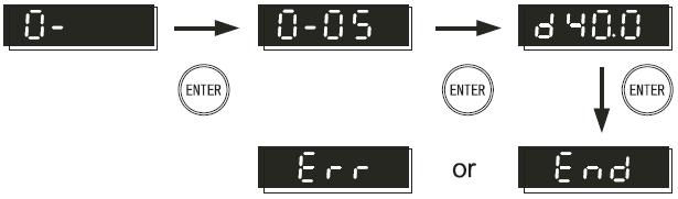
19 Description of indicator light RUN Operation indicator light: it will light on when the inverter is in operation state. STOP Stop indicator light:: it will light on when the inverter is in stop state. FWD Forward indicator light: it will light on when the rotating direction of inverter is forward. REV Reverse indicator light: it will light on when the rotating direction of inverter is reversal. Note: In the following several states, indicator lights are combined to indicate the inverter state. Set the inverter to operate, RUN indicator light is on and STOP flickers when the output frequency is 0. Set the inverter to stop, RUN indicator light flickers and STOP is on when the output frequency hasn t decreased to 0. If it is necessary to set the inverter to do the reverse operation when it is in forward operation state, stop the forward operation first, then start the reverse operation. The FWD indicator light flickers and REV is on before the forward rotating stops. If it is necessary to set the inverter to do the forward operation when it is in reverse operation state, stop the reverse operation first, then start the forward operation. The FWD indicator light is on and REV flickers before the reverse rotating stops. Descriptions of Functional Displaying Project Display Project Description Showing the current set frequency of inverter. Displaying actual frequency output from inverter to motor Displaying physical quantity(u) defined by users (U=H* 0-05) Displaying count value(c) of internal counter Displaying output current of U, V and W at output side of the inverter Displaying parameter project. Content of this parameter shall be displayed by pressing ENTER. Displaying parameter content value. Modified materials shall be stored by pressing ENTER. If END information (as diagram left shows) lasts for about 1 sec, it means that data has been received and memorized automatically. If data needs modifying, it shall be completed by acting directly with UP / DOWN and depress ENTER key again. This interface will be displayed when setting parameters are not received.


20 2. DESCRIPTION OF PANELOPERATION Scenes Selection Configuration Setup Data Modification Steering Setup
21 3. PRELIMINARY OPERATION-NOT CONNECTING WITH MOTOR Prior to connecting power supply with inverter, check and make sure that AC power supply voltage is within input voltage range of the inverter. Connect power supply to L1/R,L2/S and L3/T input terminals of the inverter. Operation mode control selection The operation mode can be divided into the following categories: Operation command is controlled by panel. (2-03=d0) (Factory setting) Operation command is controlled by external terminals, STOP key on panel is valid. Two line operation control, FWD/STOP and REV/STOP (2-03=d1, 4-04=d1) Operation command is controlled by external terminals, STOP key on panel is valid. Two line operation control, FWD / REV and OPERATION/STOP control configuration. (2-03=d1, 4-04=d2) 3-wire operation control mode Configuration 1 (2-03=d1, 4-04=d3) 3-wire operation control mode Configuration 2 (2-03=d1, 4-04=d4)


22 Operation command is controlled by communication (2-03=d3/d4 [STOP key valid/invalid])
23 Ⅳ. LIST OF DESCRIPTIONS FOR FUNCTIONAL PARAMETERS 0. User s parameters set during running available Parameter Parameter functions Setting range Factory setting 1:200V/0.2KW 2:200V/0.4KW 3:200V/0.75KW 4: 200V/1.5KW : 200V/2.2KW Inverter type code recognition Factory 6 to 9: Reserved (Only for Reading) setting 10:400V/0.4KW 11:400V/0.75KW 12:400V /1.5KW 13:400V/2.2KW 14:400V/3.7KW 200V/0.2KW:1.6A 200V/0.4KW:2.5A 200V/0.75KW:4.2A 200V/1.5KW:7.5A 0-01 Rated Current Display for 200V/2.2KW:11.0A Factory Inverter (Only for Reading) 400V/0.4KW:1.5 A setting 400V/0.75KW:2.5 A 400V/1.5KW:4.2A 400V/2.2KW:5.5A 400V/3.7KW:8.2A 0-02 Data initialization 0 to 9,11 to 20:No function 10: Parameter reset to factory setting 0 0: F(Display set frequency reference) 0-03 Machine ON Display Selection 1: H(Display actual running frequency) 2: U (Display multi-function determination) 3: A(Display motor running current) 0 0: Displaying output physical quantity(u) defined by operators 1: Displaying count value (c) 2: Displaying program operation content (X=tt) : Displaying rotating speed(r ) 6: Output frequency 2 (after slip compensation) (h) 7: Input power (p) 8 to 15:Reserved Determining multifunctional 3: Displaying DC-BUS voltage(u) display 4: Displaying output voltage (E) Proportional constant setting 0.1 to Software Version Only for reading #.## 0-07 Input parameter password protection 0 to Setting parameter password 0 to 999 0
24 protection 0-09 Reserved Parameters marked with reserved will be displayed, but will not be used for the inverter. Please do not change the code of such kind of parameter. 1. Basic Parameters Set during running available Parameter Parameter functions Setting range Factory setting 1-00 Maximum frequency 5.0 to 400Hz Base frequency 10.0 to 400.0Hz Rated voltage at base frequency 200V:2.0 to 255.0V V:2.0 to 510V Intermediate frequency setting 0.1 to 400Hz Intermediate voltage setting* 200V:2.0 to 255V V:2.0 to 510V Starting frequency 0.1 to 60.0Hz Output voltage at starting 200V:2.0 to 255V 12.0 frequency 400V:2.0 to 510V Frequency limiter(upper) 1 to 110% Frequency limiter(lower) 0 to 100% Acceleration time to 600s Deceleration time to 600s Acceleration time to 600s Deceleration time to 600s Acceleration time (JOG) 0.01 to 600s Deceleration time (JOG) 0.01 to 600s JOG frequency setting 1.0 to 400Hz Reserved 1-17 Reserved 1-18 Reserved 1-19 V/f curve setting 0 to 6 0 Parameters marked with reserved will be displayed, but will not be used for the inverter. Please do not change the code of such kind of parameter. 2. Operation mode parameters Set during running available Parameter Parameter functions Setting range 0: Keys on keypad 1: Input DC 0 to 10V by external terminals 12 2: Input DC 4 to 20mA by external terminals C1 3: Controlled by VR on keypad 2-00 Frequency command 1 4:Operated by RS-485 communications interface 5:Operated by RS-485 communications interface(frequency memory) 6:Controlled by UP/DOWN 7:Controlled by UP/DOWN (Frequency memory) 8: Reserved Factory setting 3
25 0: Keys on keypad 2-01 Frequency command 2 1: Input DC 0 to 10V by external terminals 12 2: Input 4 to 20Ma by external terminals C1 3: controlled by VR on keypad 4: reserved 5: reserved 6: Controlled by UP/DOWN 7:Controlled by UP/DOWN (Frequency memory) 8:reserved 0 0: Frequency command : Frequency command 1+ Frequency command Combination way of frequency 2 sources 2: Frequency command 1- Frequency command 2 0 0: Operated by keypad 1: Operated by external terminals. STOP on keypad available 2: Operated by external terminals. STOP on 2-03 Operation method keypad unavailable 3: Operated by Communications Interface RS-485. STOP on keypad available 4: Operated by Communications Interface RS-485. STOP on keypad unavailable Deceleration mode 0: Normal deceleration 1: Coast to stop Reserved 2-06 External fault (EF) stop mode 0: Reserved 1: External fault (EF) coast to stop 1 0:Deceleration stop 2-07 stop Reference loss detection 1:Coast to stop (Terminal 12)( stop mode) 2:Holding operation command after deceleration Reserved 2-09 Motor sound(carrier frequency) 2.0 to 12.0kHz 6.0 0: Fwd/Rev run available 2-10 Rotation direction inhibition 1: Rev run inhibited 2: Fwd run inhibited 0 0: Non-processing 2-11 Reference loss detection (Terminal C1) ( stop mode) 1: Coast to stop 2: EF display after deceleration stop 3: Continuous operation by reference frequency before disconnection Power on start 0: Operation available 1: Operation unavailable to 2-14 reserved Parameters marked with reserved will be displayed, but will not be used for the inverter. Please do not change the code of such kind of parameter.
26 Notes: 1)In 2-00 and 2-01, when 2-00 has been set as d1(12) or d2(c1), 2-01 can't be set as d1 or d2 again. 2)In 2-00 and 2-01, when 2-00 has been set as d6 or d7 (controlled by UP/DOWN), 2-01 can't be set as d6 or d7 again. 3) The parameter of 2-07 is valid only when the frequency is given by analog input 12 and input set 0. If the frequency is given by 12, but press the STOP key, the inverter will stop still according to the mode of Output Function Parameters Set during running available Parameter Parameter functions Setting range Factory setting 3-00 Frequency detection(level) 1.0 to 400Hz Count value agreement setting 0 to Appointed count agreement setting 0 to Fwd run reference delay setting 0.0 to 60.0s Rev run reference delay setting 0.0 to 60.0s 0.0 0: No function Terminal[30A/B/C] Function(Relay output) 1: Inverter running 2:Frequency arrival 3: Zero speed 4: Over-torque detection 5: During external alarm 6. Low voltage detection 7: External terminal running mode 8: Alarm output (for any alarm) 3-05 Normally Open 9: Frequency detection Contactor(30A-30C) 10:During pattern operation 8 Normally Closed Contactor(30B-30C) 11. Pattern operation one cycle completion 12. Pattern operation completion 13: Pattern operation pause 14:Terminal count value arrival 15: Terminal designated count value arrival 16: Inverter ready to run 17: Fwd running 18: Rev running 19: Fwd/ Rev run direction 0:Output frequency 1 (before slip compensation) 3-06 Analog output setting 1:Output frequency 2 (after slip compensation) 2:Analog current meter(0 to 250% of rated current) 3: Analog output voltage 4: Analog DC bus voltage 5: Input power Reserved 3-08 Analog output gain selection 1 to 200% 100 0: No function 3-09 Terminal [Y1] Function 1: Inverter running 2:Frequency arrival 1
27 3: Zero speed 4: Over-torque detection 5: During external alarm 6. Low voltage detection 7: External terminal running mode 8: Alarm output (for any alarm) 9: Frequency detection 10:During pattern operation 11. Pattern operation one cycle completion 12. Pattern operation completion 13: Pattern operation pause 14:Terminal count value arrival 15: Terminal designated count value arrival 16: Inverter ready to run 17: Fwd running 18: Rev running 19: Fwd/ Rev run direction 3-10 Reserved 3-11 Dead time setting of Fwd and 0.0 to 600 s Rev changeover 0.0 0:Fan continuous running 3-12 Cooling fan control 1: Run for 1 minute after pressing stop key 2: Operate/stop along with inverter Bias [12] (Bias base point) 0.0 to 10.0V Bias [12] (Bias value) 0.0 to 100% of Maximum Frequency Analog input Adjustment for [12] (Gain base point) 0.0 to 10.0V Analog input Adjustment for [12] (Gain) 0.0 to 100% of Maximum Frequency Bias [C1] (Bias base point) 0.0 to 20.0mA Bias [C1] (Bias value) 0.0 to 100% of Maximum Frequency Analog input Adjustment for [C1] (Gain base point) 0.0 to 20.0mA Analog input Adjustment for [C1] (Gain) 0.0 to 100% of Maximum Frequency reserved 3-22 reserved Parameters marked with reserved will be displayed, but will not be used for the inverter. Please do not change the code of such kind of parameter.
28 4. Input Function Parameters Set during running available Factory Parameter Parameter functions Setting range setting [VR] Input frequency bias 0.0 to 350Hz 0.0 setting [VR] Input frequency bias adjustment direction [VR] Input frequency gain setting [VR] Negative bias operation setting Terminal (FWD) function (Setting range from d0 to d31)* Terminal (REV) function (Setting range d0, d5 to d31) Terminal (X1) function (Setting range d0, d5 to d31) Terminal (X2) function 4 Setting range d0, d5 to d31) Terminal (X3) function (Setting range d0, d5 to d31) 0: Positive direction 0 1: Negative direction 1 to 200% 100 0: No negative bias 1: Reversible negative bias 0 2: not reversible negative bias 0: No function 1: FWD: forward run/stop, REV: reverse run/stop 2: FWD: run/stop, REV: fwd/rev run 3: 3-line operation control(1): FWD run, REV fwd/rev 1 run, X1 STOP(Normally closed) 4: 3-line operation control(2): FWD run (Triggering), REV run(triggering), X1 STOP(Normally closed) 5: External fault(ef), normally open interface input (N.O) 6: External fault(ef) normally closed interface input 0 (N.C) 7: RESET alarm 8: Select multi-frequency (0 to 1 steps) 9: Select multi-frequency (0 to 3 steps) 10: Select multi-frequency (0 to 7 steps) 8 11: Reserved 12: Select frequency command 2/1 13: Accel /decel inhibition command 14: Select 1 ST and 2 nd Accel/Decel time 9 15: External alarm, normally open (NO) input 16: External alarm, normally closed(nc) input 17: Up command 18: Down command 19: Pattern operation command 20: Pattern operation pause command 21: JOG frequency reference 22: Count reset 23: Reserved 7 24: JOG-FWD 25: JOG-REV 26: Reserved 27: Wobble frequency function input 28: Wobble frequency state reset 29: Inhibiting output (N.O) 30 :Inhibiting output (N.C)
29 31: Counter trigger signal input :Tracking downwards from speed before external Speed tracking after external alarm alarm reset 1:Tracking upwards from min speed ~4.22 Reserved Parameters marked with reserved will be displayed, but will not be used for the inverter. Please do not change the code of such kind of parameter. Notes: When 4-04 is set as d1~d2, function set by REV is invalid. When 4-04 is set as d3~d4, function set by REV and X1 is invalid. 5. Multi-step Speed and Auto-Program Operation Parameters Set during running available Parameter Parameter functions Setting range Factory setting 5-00 Multi frequency to 400Hz Multi frequency to 400Hz Multi frequency to 400Hz Multi frequency to 400Hz Multi frequency to 400Hz Multi frequency to 400Hz Multi frequency to 400Hz Reserved 5-08 Reserved 5-09 Reserved 5-10 Reserved 5-11 Reserved 5-12 Reserved 5-13 Reserved 5-14 Reserved 0. Pattern operation inactive 5-15 Pattern Operation(Mode) 1. Active (Stop after operating for 1 cycle) 2. Active (Pattern operation performs in cycles until STOP command input) 3. Active (Stop after operating for 1 cycle) (with STOP intervals). 4. Active (Pattern operation performs in cycles until STOP command input) (with STOP intervals). 0 5~16 (Rotating Operation) (0 to 7 th step speed) 0 to 255( 0: Forward Run 1: Reverse Run) Reserved 5-18 (Step 0 Time) 0 to 65500S (Step 1 Time) 0 to 65500S (Step 2 Time) 0 to 65500S (Step 3 Time) 0 to 65500S (Step 4 Time) 0 to 65500S (Step 5 Time) 0 to 65500S (Step 6 Time) 0 to 65500S (Step 7 Time) 0 to 65500S Reserved
30 5-27 Reserved 5-28 Reserved 5-29 Reserved 5-30 Reserved 5-31 Reserved 5-32 Reserved 5-33 Reserved Parameters marked with reserved will be displayed, but will not be used for the inverter. Please do not change the code of such kind of parameter. 6. Protection Parameters Set during running available Parameter Parameter functions Setting range Factory setting : Inactive Over voltage stall prevention V series: V function V series: V 6-01 Reserved 0: No detection : Over torque detection (OL2) during constant speed running, continue to run after detection. 2: Over torque detection (OL2) during constant Over-torque detection (Mode speed running, stop running after detection. selection) 3: Over torque detection (OL2) during acceleration, continue to run after detection. 4: Over torque detection (OL2) during acceleration, stop running after detection Over torque detection (Detection level) 30 to 200% Over torque detection time 0.1 to 10.0s 0.1 0:Inactive 6-05 Electrical thermal overload protection for Motor (Select motor characteristics) 1: Active(For a general-purpose motor with shaft-driven cooling fan) 2: Active(For a motor with separately powered cooling fan) Electrical thermal overload protection for Motor 30 to 600S 60 (Thermal time constant) 6-07 Alarm history (Latest) 0: No alarm records Alarm history (1 st last) 1: OC (Over current) Alarm history (2 nd last) 2: OV(Over voltage) Alarm history (3 rd last) 3: OH(Over heating) Alarm history (4 th last) 4: OL(Inverter overload) 0 5 :OL1(Motor overload) 6-12 Alarm history (5 th last) 6: EF(External fault) 16:CF2(Read error of internal storage IC data) 17:External alarm signal input 18: OL2(Motor overload) 22: CF3.1(Internal temperature is over high or circuit 0
31 alarm at power-on test) 23: CF3.2(Over voltage of internal DC voltage side at power-on test) 24:CF3.3(Under voltage of internal DC voltage side at power-on test) 29: HPF.1 (Over voltage protection circuit alarm) 31:HPF.3 (Over current protection circuit alarm) 37:Errb(Wobble frequency setting error) 7. Motor Parameters Set during running available Parameter Parameter functions Setting range Factory setting 7-00 Motor(Rated current) 30 to 120% Motor(No load current) 0 to 90% Reserved 7-03 Auto slip compensation setting 0.0 to ~7-10 Reserved 7-11 Motor(Rated speed) 500 to 3000min Motor(Pole number) 0 to 30pole Motor(Rated frequency) 5.0 to 400Hz ~7-40 Reserved 7-41 External input terminals Eliminate jitter time 1 to 255ms ~7-74 Reserved Parameters marked with reserved will be displayed, but will not be used for the inverter. Please do not change the code of such kind of parameter. 8. High Function Parameters Set during running available Parameter Parameter functions Setting range Factory setting 8-00 DC braking(braking level) 0.0 to 100% DC braking(braking time setting at starting) 0.0 to 60.0S DC braking(braking time setting at stopping) 0.0 to 60.0S DC braking(braking starting frequency) 0.1 to 60.0Hz 1.0 0:Inactive(Trip immediately) 1:Active(Restart at the frequency at :Active(Restart at the starting frequency, for light inertia loads) Restart after momentary power failure (Mode which the power failure occurred, for selection) general loads) (Max allowable time for power failure) 0.3 to 5.0s (Restart time) 0.3 to 5.0s (Max current setting for speed tracking) 30 to 200% Jump frequency 1(Upper) 0.0 to 400Hz Jump frequency 1(Lower) 0.0 to 400Hz Jump frequency 2(Upper) 0.0 to 400Hz Jump frequency 2(Lower) 0.0 to 400Hz Jump frequency 3(Upper) 0.0 to 400Hz Jump frequency 3(Lower) 0.0 to 400Hz Auto-reset(Times) 0 to 10 0
32 0:AVR function available 8-15 AVR function selection 1:AVR function unavailable 2:AVR function cancelled during 1 deceleration 8-16~8-18 Reserved 8-19 Reserved 8-20 Auto-reset(Counter clear time) 1 to 100 min Reserved 8-22 Auto-reset(Reset interval) 0.1 to 20.0s 2.0 Parameters marked with reserved will be displayed, but will not be used for the inverter. Please do not change the code of such kind of parameter. 9. Communications Parameters Set during running available Parameter Parameter functions Setting range Factory setting 9-00 RS-485 Communications Station address (inverter number) 1 to :Baud rate 4800 bps 9-01 (Baud rate) 1: Baud rate 9600 bps 2:Baud rate bps 3: Baud rate bps 4: Baud rate bps 1 0:Warning and running continuously 9-02 (Communications error processing) 1:Warning and deceleration to stop 2:Warning and coasting to a stop 3:No warning and running continuously (No-response error detection time) 0: Not detected 1 to 20s 0 0:ASSII mode <8, N,1> 1: ASSII mode <8, N,2> 2: ASSII mode <8, E,1> 3: ASSII mode <8, E,2> :RTU mode <8, N,2> 7: RTU mode <8, E,1> 8: RTU mode <8, O,1> 9 to 11 :Reserved (Communications format ) 4: ASSII mode <8, O,1> <Data length, Parity, STOP bit> 5: ASSII mode <8, O,2> 0 0:Warning and running continuously 9-05 Communication Troubleshooting 1:Warning and deceleration to stop 2:Warning and coasting to a stop 3:No warning and running continuously Reserved 9-07 (Response interval) 0 to 200 (one unit=2ms) 1 Parameters marked with reserved will be displayed, but will not be used for the inverter. Please do not change the code of such kind of parameter.
33 A. Wobble Frequency Function Parameters Set during running available Parameter Parameter functions Setting range Factory setting A-00 Wobble frequency selection 0:Not applying 1:Applying 0 A-01 Wobble frequency input mode 0:Set according to wobble frequency action delay 0 1:Controlled by external terminals. A-02 Pre-set frequency of Wobble Frequency 0.0 to 400Hz 0.0 A-03 Action delay setting of preset wobble 0.0 to 600(s) frequency 0.0 0:According to operation frequency A-04 Central frequency of wobble frequency source 1:According to fixed frequency setting 0 (A-05) A-05 Fixed central frequency setting of wobble frequency (Max frequency base) 0.01 to 100% 20.0 A-06 Reference source setting for wobble 0: Centering frequency base aptitude 1: Max frequency(1-00) base 0 A-07 Wobble aptitude width setting 0.0 to 50.0% 0.00 A-08 Wobble frequency hopping (relative aptitude) 0.0 to 50.0% 0.00 A-09 Wobble frequency cycle 0.1 to 655s 10.0 A-10 Triangle wave rising time(relative cycle) 0.1 to 99.9% 50.0 A-11 Wobble frequency machine stop starting 0:Starting in memorizing state before stop mode 1:Restarting 0 A-12 Wobble state power loss memory 0:Memorizing 1:Non-memorizing 0
34 Ⅴ. DESCRIPTION OF FUNCTIONAL PARAMETERS All the functional parameters are described in detail in this chapter. According to attributes, the parameters can be divided into 11 groups; in most of the applications, presetting for operation shall be completed by performing with these parameters of groups. The 11 groups of parameters are listed as below: 0: User s Parameters 1: Basic Parameters 2: Operation Mode Parameters 3: Output Function Parameters 4: Input Function Parameters 5: Multi-step and Pattern Operation Parameters 6: Protection Parameters 7: Motor Parameters 8: High Function Parameters 9: Communications Parameters A : Wobble Frequency Function Parameters *: indicates that for 400V class, value shall be 2 times of setting. : indicates that it s available to be set during running. Parameters marked with reserved will be displayed, but will not be used for the inverter. Please do not change the code of such kind of parameter. 0. USER'S PARAMETERS 0-00 Inverter type code recognition (only for reading) Factory setting d# Setting range Non Inverter type code shall be read through this parameter, and for capacity of the drive, which has been set at factory, please see diagram below. Also, it shall be applied to judge whether current in parameter (0-01) corresponds with rated current of the specific machine. Parameter 0-00 corresponds with 0-01 as the diagram below indicates. 200V(type code) d1 d2 d3 d4 d5 Power kw Horsepower HP Rated current 0-01(A) V(type code) d10 d11 d12 d13 d14 Power KW Horsepower HP Rated current 0-01(A) Rated current display of inverter (only for reading) Factory setting d#.# Setting range Non This parameter displays the rated current of inverter, corresponding to machine types displayed at Parameter Data initialization Factory setting d 0 d 0<->20 No action Setting range d 10 All parameters reset to factory setting This parameter enables users to reset all parameters to factory setting.
35 0-03 Machine On display Selection Factory setting d 0 d 0 F (Displaying set frequency reference) Setting range d 1 H(Displaying actual running frequency) d 2 U(Displaying multifunctional definitions ) d 3 A( displaying motor running current) This parameter enables users to determine the machine ON display by themselves Determining multifunctional display Factory setting d 0 d 0 Displaying output physical quantity(u) defined by operators d 1 Displaying count value (c) d 2 Displaying program operation content (X=tt) d 3 Displaying DC-BUS voltage(u) Setting range d 4 Displaying output voltage (E) d 5 Displaying rotating speed(r ) d 6 Output frequency 2 (after slip compensation) (h) d 7 Input power (p) d8<->d15 Reserved Output physical quantity defined by users shall be displayed when it is set to d0 (Physical quantity =H 0-05) 0-05 Proportional constant setting Factory setting d 1.0 Setting range d 0.1<->d 160 Unit 0.1 Proportional constant K, the constant used in output physical quantity defined by users. This parameter should be used in conjunction with d0, d5 and d6 of The display value shall be counted as this formula shown below: When set 0-04 as d0, display value= Output frequency (before slip compensation) x K (0-05) When set 0-04 as d5 display value= rotating speed x K (0-05). When set 0-04 as d6, display value= Output frequency 2 (after slip compensation) x K (0-05) Software Version Factory setting d #.## Setting range Non Software version is only for reading Input parameters password protection Factory setting d 0 d 0<->d 999 Setting range d0 No code locking or correct code has been input d1 Parameters have been locked When this parameter indicates as d1, all parameters have been locked. Correct password must be entered to make this parameter able to write. This parameter will display d0 after entering the correct password. It will be locked again if incorrect password is entered. After having entered the correct password, all parameters can be set before this interruption of power supply. However, if the value of 0-08 isn t cleared, which means the password protection function hasn t been cancelled, the correct password must be entered again to modify parameters when power on next time. End will be displayed whether the parameter password is entered correctly or not, otherwise Err will be displayed. This password has three times of entering limit to prevent from entering password arbitrarily. If enter wrong password three times continuously, Err will be displayed. It is necessary to reboot the power supply to enter password again.
GS1 Parameter Summary Detailed Parameter Listings...4 9
 CHAPTER AC DRIVE 4 PARAMETERS Contents of this Chapter... GS1 Parameter Summary...............................4 2 Detailed Parameter Listings..............................4 9 Motor Parameters.........................................4
CHAPTER AC DRIVE PARAMETERS. In This Chapter...
 CHAPTER AC DRIVE 4 PARAMETERS In This Chapter... GS2 Parameter Summary....................4 2 Detailed Parameter Listings.................4 11 Motor Parameters........................4 11 Ramp Parameters.........................4
CHAPTER 8 SUMMARY OF PARAMETER SETTINGS
 CHAPTER 8 SUMMARY OF PARAMETER SETTINGS VFD-S Series!: The parameter can be set during operation, *: Twice the value for 460V class. Group 0 User Parameters Parameters Explanation s 0-00 Identity Code
CHAPTER 8 PARAMETER SUMMARY
 CHAPTER PARAMETER SUMMARY Group 0: System Parameter VFD-V Series 00-00 Identity Code Based on the model type 00-01 Rated Current Display 00-02 Parameter Reset 00-03 00-04 Star-up Display of the Drive Definitions
D SERIES EM16 IP 20 / NEMA 1 & IP 66 / NEMA 4X COMPACT VECTOR CONTROL DRIVE EM 16 COMPACT VECTOR CONTROL DRIVE
 D SERIES EM16 IP 20 / NEMA 1 & IP 66 / NEMA 4X COMPACT VECTOR CONTROL DRIVE EM 16 COMPACT VECTOR CONTROL DRIVE 1 2 SERIES 1 2 pag. 4 pag. 5 Applications Model identification 3 pag. 5 4 pag. 6 Capacity
Operation Instructions NORDAC SK 400E. Frequency Inverter. SK 400E B / SK 400E B (0.4kW / 0.7kW, 1~ 115V)
") NORDAC SK4E Safety Instructions Operation Instructions NORDAC SK 4E Frequency Inverter SK 4E-2-111-B / SK 4E-4-111-B (.4kW /.7kW, 1~ 115V) SK 4E-2-123-B... SK 4E-151-323-B (.2kW 1.5kW, 1/3~ 23V, 3~ 23V)
NORDAC SK4E Safety Instructions Operation Instructions NORDAC SK 4E Frequency Inverter SK 4E-2-111-B / SK 4E-4-111-B (.4kW /.7kW, 1~ 115V) SK 4E-2-123-B... SK 4E-151-323-B (.2kW 1.5kW, 1/3~ 23V, 3~ 23V)
Manual Overview...1 2
 GETTING STARTED CHAPTER 1 Contents of this Chapter... Manual Overview.....................................1 2 Overview of this Publication..................................1 2 Who Should Read This Manual...............................1
TOSVERT TM VF-nC3 Parameter List
 TOSVERT TM VF-nC Parameter List E658664 - Setting information * Please fill it in if necessary. Item Content Item Content Setting date / person Customer Application Application model Motor manufacturer
Ambient Conditions Storage Conditions Installation Minimum Clearances and Air Flow...2 3
 CHAPTER INSTALLATION 2 AND WIRING Contents of this Chapter... Ambient Conditions..............................2 2 Storage Conditions...............................2 2 Installation.....................................2
Operating Instructions
 4XH35QB151210 Small General Frequency Converter Operating Instructions 220V 0.75KW 5.5KW 400V 0.75KW 15KW Please read the instruction carefully and understand the contents so that it can be installed and
Index 2. G Gain settings 4 31 Glossary of terms A 2 Grommets 2 13
 Index A A Group functions 3 9 AC reactors 5 3 Acceleration 1 15, 3 8 characteristic curves 3 26 second function 3 24 two-stage 4 19 Acceleration stop function 3 21 Access levels 3 5, 3 36, 4 25 Access
This operation manual is intended for users with basic knowledge of electricity and electric devices.
 This operation manual is intended for users with basic knowledge of electricity and electric devices. Safety Information Safety Information Read and follow all safety instructions in this manual precisely
General Specifications FECA-TE /2010. Phone: Fax: Web:
 General Specifications FECA-TE-117 06/2010 1. Standard Specifications 1) Three-phase 230V series Output ratings Input ratings Braking Item Specifications Type (FRN C1S-2U) F12 F25 F50 001 002 003 005 Nominal
TECO F510 Inverter. Quick Start Guide. Step 1. Supply & Motor connection
 Quick Start Guide TECO F510 Inverter This guide is to assist you in installing and running the inverter and verify that it is functioning correctly for it s main and basic features. For detailed information
CHAPTER 5 DESCRIPTION OF PARAMETER SETTINGS
 CHAPTER DESCRIPTION OF PARAMETER SETTINGS.1 Group 0: System Parameter VFD-V Series 00-00 Identity Code Factory setting Read Only Settings Based on the model type 00-01 Rated Current Display Factory setting
Fan and Pump AC Inverter
 Fan and Pump AC Inverter Key Features for Fan and Pump Applications PID and Auto Energy Saving Functions. Input Phase Loss and Output Phase Loss Protection. LCD Keypad can be used to copy parameter settings
S11 Adjustable Speed Drive Engineering Specification
 PART 1 - GENERAL 1.0 Scope This specification shall cover Toshiba S11 AC Variable Frequency Drives, 6 pulse for 3- phase 200-240VAC, 380-500VAC and single phase 200V to 240VAC. 1.1 References A. National
SYSDRIVE 3G3XV Inverter 3G3XV- -EV2 Operation Manual
 SYSDRIVE 3G3XV Inverter 3G3XV- -EV2 Operation Manual Revised November 1997 iv Notice: OMRON products are manufactured for use according to proper procedures by a qualified operator and only for the purposes
AV-300i Specifications. Saftronics Inc. PC10 Product Specifications PC10. Mini Vector AC Drive
 Saftronics Inc. www.saftronics.com TM AV-300i Specifications PC10 Product Specifications PC10 Mini Vector AC Drive 1 (1) T hree-phas e 230V input Drive Hp 1/8 1/4 1/2 1 2 3 5 7.5 10 Nominal applicable
VF-nC1 Adjustable Speed Drive Engineering Specification
 PART 1 - GENERAL 1.0 Scope This specification shall cover Toshiba VF-nC1 AC Variable Frequency Drives, 6 pulse for 100V single-phase 0.1 to 0.75kW, 200V single-phase 0.2 to 2.2kW and 200V threephase 0.1
INDEX. i 1. B Braking Resistor Dimensions: A 24 Braking Resistors: A 20 Braking Units: A 20. DURAPULSE AC Drive User Manual
 INDEX A AC Drive Cover: 1 6 Dimensions: 2 4 External Parts and Labels: 1 6 Heat Sink Fins: 1 6 Input Mode Switch (Sink/Source): 1 6 Introduction to DuraPulse GS3 AC drive: 1 3 Keypad: 1 6 Model Number
FREQUENCY INVERTER VFR-013 QUICK START GUIDE
 FREQUENCY INVERTER VFR-013 QUICK START GUIDE Inoréa Automation & Industry 9 rue du Lugan 33130 BEGLES www.inorea.com Table of contents 1. PEOPLE SAFETY... 3 2. MATERIAL SAFETY... 3 3. NAME PLATE... 4 a.
ATV12H037F1 variable speed drive ATV kW hp V - 1ph - with heat sink
 Characteristics variable speed drive ATV12-0.37kW - 0.55hp - 100..120V - 1ph - with heat sink Main Range of product Altivar 12 Product or component type Product destination Product specific application
6.9 Jump frequency - Avoiding frequency resonance
 E581595.9 Jump frequency - Avoiding frequency resonance : Jump frequency : Jumping width Function Resonance due to the natural frequency of the mechanical system can be avoided by jumping the resonant
ATV12H018F1 variable speed drive ATV kW hp V - 1ph
 Characteristics variable speed drive ATV12-0.18kW - 0.25hp - 100..120V - 1ph Main Range of product Altivar 12 Product or component type Product destination Product specific application Assembly style Component
CHAPTER 5 DESCRIPTION OF PARAMETER SETTINGS
 CHAPTER DESCRIPTION OF PARAMETER SETTINGS.1 Group 0: User Parameters 0-00 Identity Code of AC Drive Factory setting: d# Settings None V HP 1/4 1/2 1 2 3 11V/230V d0 d2 d4 d6 d8 460V -- -- -- d3 d d7 d9
SAFETY INSTRUCTIONS WARNING
 Important User Information Thank you for purchasing LS Variable Frequency Drives! SAFETY INSTRUCTIONS Always follow safety instructions to prevent accidents and potential hazards from occurring. In this
VFD - D700 Series Specifications. The latest low-cost variable speed control solution for centrifugal pumps.
 VFD - D700 Series Specifications The latest low-cost variable speed control solution for centrifugal pumps. Built-in PID Control to maintain pressure, flow, measured value, and much more 125% overload
CHAPTER MAINTENANCE AND TROUBLESHOOTING. In This Chapter... Maintenance and Inspection Troubleshooting...6 3
 CHAPTER MAINTENANCE AND 6 TROUBLESHOOTING In This Chapter... Maintenance and Inspection.................6 2 Monthly Inspection:..................................6 2 Annual Inspection....................................6
VS-616PC5/P5 Series User s Manual
 VS-616PC5/P5 Series User s Manual Variable Torque Inverter PRECAUTIONS! WARNING 1) Read this manual in its entirety before installing or operating the VS- 616PC5/P5 inverter. 2) Do not connect or disconnect
Caution. Three-phase 400V series FRN0.4C1S-4A FRN0.75C1S-4A FRN1.5C1S-4A FRN2.2C1S-4A FRN3.7C1S-4A
 Variation Caution The contents of this catalog are provided to help you select the product model that is best for you. Before actual use, be sure to read the User s Manual thoroughly to assure correct
VLT MICRO Series Adjustable Frequency Drive Instruction Manual
 VLT MICRO Series Adjustable Frequency Drive Instruction Manual 1/00 23-6127-00 Revision DR 2 Table of Contents Chapter 1 Chapter 2 Chapter 3 Introduction Getting Started... 5 Receiving, Inspection, and
FUJI Inverter. Standard Specifications
 FUJI Inverter o Standard Specifications Norminal applied motor The rated output of a general-purpose motor, stated in kw. That is used as a standard motor. Rated capacity The rating of an output capacity,
E3 Adjustable Speed Drive Engineering Specification
 E3 Adjustable Speed Drive Engineering Specification PART 1 - GENERAL 1.0 Scope This specification shall cover Toshiba E3 AC Variable Frequency Drives, 6 pulse for 230V and 460V. 1.1 References A. National
Warning!! 2. The drive contains high voltage that can cause electric shock resulting in personal injury or loss of life.
 ! Warning!! 1. Please read this manual completely before installing the drive. 2. The drive contains high voltage that can cause electric shock resulting in personal injury or loss of life. 3. Be sure
CHAPTER 3 WIRING DANGER
 CHAPTER WIRING DANGER Hazardous Voltage Before accessing the AC drive: Disconnect all power to the AC drive. Wait five minutes for DC bus capacitors discharge. Any electrical or mechanical modification
SYSDRIVE 3G3HV Inverter Models The following 200- and 400-V class 3G3HV Inverter models are available.
 Function The 3G3HV High-capacity General-purpose Inverter is an easy-to-use inverter that has advanced features, such as PID control and energy-saving operations. SYSDRIVE 3G3HV Inverter Models The following
FE0 9
 5011613009 2011-04- 18 FE0 9 Preface Thank you for choosing DELTA s high-performance VFD-F Series. VFD-F Series are manufactured by adopting high-quality components, material and incorporating the latest
VFS11 Parameter List for up to CPU version 105
 E65824 VFS Parameter List for up to CPU version 5 Setting Date Customer End user Application Application No/Serial No Inverter s Type-Form Quantity Inverter s Serial No Motor s capacity If user s value
ADJUSTABLE SPEED DRIVES. AS1 Drive
 ADJUSTABLE SPEED DRIVES AS1 Drive Toshiba s New ASD Product Line The AS1 drive builds on Toshiba s history of supplying powerful, reliable, and versatile drives. We have combined our best drive features
Varispeed V7 INSTRUCTION MANUAL
 YASKAWA Varispeed V7 INSTRUCTION MANUAL COMPACT GENERAL-PURPOSE INVERTER (VOLTAGE VECTOR CONTROL) FOR CC-Link COMMUNICATIONS Upon receipt of the product and prior to initial operation, read these instructions
VSC. Instruction Manual - English
 VSC Instruction Manual - English Quick Start Guide This guide is to assist in installing and running the inverter to verify that the drive and motor are working properly. Starting, stopping and speed control
ATV12HU40M3 variable speed drive ATV12-4kW - 5hp V - 3ph - with heat sink
 Characteristics variable speed drive ATV12-4kW - 5hp - 200..240V - 3ph - with heat sink Main Range of product Altivar 12 Product or component type Product destination Product specific application Assembly
LG Variable Frequency Drive
 LG Variable Frequency Drive ig5 Series 0.5-5.4HP (200/400V) Installation, Operation and Maintenance Instruction Read this manual carefully before installing, wiring, operating, servicing or inspecting
Multi-function, Compact Inverters. 3G3MV Series
 Multi-function, Compact Inverters 3G3MV Series There has been a great demand for inverters with more functions and easier motor control than conventional i OMRON's powerful, compact 3G3MV Series with versat
Safety Instructions WARNING. Do not remove the cover while power is applied or the unit is in operation.
 Thank you for purchasing L&T inverter! Safety Instructions Read this manual carefully before installing, wiring, operating, servicing or inspecting this equipment. The safety instructions are divided into
VARISPEED V7 IP65 Compact Sensorless Vector Inverter USER S MANUAL
 V7_IP65.qxd 15.02.2006 13:17 Uhr Seite 1 Manual No. I161E-EN-01 VARISPEED V7 IP65 Compact Sensorless Vector Inverter USER S MANUAL OMRON YASKAWA MOTION CONTROL B.V. Wegalaan 65 2132 JD Hoofddorp The Netherlands
D SERIES LM16. COMPACT DRIVE V/f and SLV CONTROL. LM16 COMPACT DRIVE V/f and SLV CONTROL
 D SERIES LM16 COMPACT DRIVE V/f and SLV CONTROL LM16 COMPACT DRIVE V/f and SLV CONTROL 1 2 SERIES 1 2 page 4 page 6 Introduction Fields of application 3 page 7 4 page 8 Designation Product offer 5 6 page
Cutes Corporation IGBT INVERTER. Instruction
 Cutes Corporation CT-2 Series IGBT INVERTER Instruction Head Office : 2-22, Nan Yuan Road, Chung Li City, Taiwan TEL: 886 3 4612333 or 886 3 4526161 ext. 275 FAX: 886 3 4526227 or 886 3 4511347 E-mail:
HITACHI. L100-M Series Inverter Quick Reference Guide. Hitachi Industrial Equipment Systems Co., Ltd. Single-phase Input 100V Class
 HITACHI L1-M Series Inverter Quick Reference Guide Single-phase Input 1V Class Hitachi Industrial Equipment Systems Co., Ltd. Manual No. NB5741XD December 23 Caution: Be sure to read the L1 Inverter Manual
NZV Series Sensorless Vector Control Inverter Operation Manual
 NZV Series Sensorless Vector Control Inverter Operation Manual Thank you very much for your buying NZV series sensorless vector control inverter. Before use, please read this manual thoroughly to ensure
GS S. Compact Space Ve VFD. Frequency and .5 5
 GS S Compact Space Ve VFD Frequency and.55.55 8 Thank you for purchasing CERUS Variable Frequency Drives! SAFETY INSTRUCTIONS Always follow safety instructions to prevent accidents and potential hazards
INSTRUCTION MANUAL FVR-E11S-7EN
 INSTRUCTION MANUAL FVR-E11S-7EN Three-phase 400V input FVR-E11S-4EN Single-phase 200V input Low noise high performance inverter Caution Thank you for purchasing our FVR-E11S series inverter. This product
THYFREC-VT230S 200V System 0.4 to 90kW 400V System 0.4 to 370kW INSTRUCTION MANUAL
 MEIDEN AC SPEED CONTROL EQUIPMENT THYFREC-VT230S 200V System 0.4 to 90kW 400V System 0.4 to 370kW INSTRUCTION MANUAL NOTICE 1. Read this manual thoroughly before using the VT230S, and store in a safe place
SE Series User Manual
 SE Series User Manual 22V 2W-2HP Simple General Purpose AC Drive ASIA SANCH ELECTRIC CO.,LTD. Sales Office/ LUO JIANG INDUSTRIAL ZONE ZHUANGREN 2#, CHINA TEL:886-595-267315 FAX:886-595-267319 Http://www.sanch.net
Instruction Manual. General application Inverter. IMO idrive2 XKL
 Instruction Manual General application Inverter IMO idrive2 XKL Thank you for purchasing our idrive2 XKL series of inverters. This product is designed to drive a three-phase induction motor. Read through
ATV12HU22M2. Main. Range of product Altivar 12. Component name Quantity per set Set of 1. Built-in fan. Motor power hp Communication port protocol
 Product datasheet Characteristics ATV12HU22M2 Complementary Main Range of product Altivar 12 Product or component type Product destination Product specific application Assembly style Component name Variable
ADTECH Solar inverter
 ADTECH Solar inverter 1. Product description Thank you very much for your selection of special solar inverter launched by ADTECH (SHENZHEN) TECHNOLOGY CO., LTD. Solar energy special inverter is designed
SECTION 16483D ADJUSTABLE FREQUENCY DRIVE - MICRODRIVE (MVX <10-HP)
") ADJUSTABLE FREQUENCY DRIVE - MICRODRIVE (MVX
ADJUSTABLE FREQUENCY DRIVE - MICRODRIVE (MVX
ATV12H037F1 variable speed drive ATV kW hp V - 1ph - with heat sink
 Characteristics variable speed drive ATV12-0.37kW - 0.55hp - 100..120V - 1ph - with heat sink Product availability : Stock - Normally stocked in distribution facility Price* : 191.76 USD Main Range of
Cat. No. I528-E1-2 USER S MANUAL SYSDRIVE 3G3JV. Compact Simplified Inverters
 Cat. No. I528-E1-2 USER S MANUAL SYSDRIVE 3G3JV Compact Simplified Inverters Thank you for choosing this SYSDRIVE 3G3JV-series product. Proper use and handling of the product will ensure proper product
[ 4 ] Using pulse train input (F01 = 12)
![[ 4 ] Using pulse train input (F01 = 12)](/thumbs/90/102625444.jpg "[ 4 ] Using pulse train input (F01 = 12)") [ 4 ] Using pulse train input (F01 = 12) Selecting the pulse train input format (d59) A pulse train in the format selected by the function code d59 can give a frequency command to the inverter. Three types
[ 4 ] Using pulse train input (F01 = 12) Selecting the pulse train input format (d59) A pulse train in the format selected by the function code d59 can give a frequency command to the inverter. Three types
INSTALLATION AND OPERATION MANUAL IODA INPUT/OUTPUT MULTI-FUNCTION BOARD (Part No. 9668)
") INSTALLATION AND OPERATION MANUAL IODA INPUT/OUTPUT MULTI-FUNCTION BOARD (Part No. 9668) Use with Models KBDA-24D, 27D, 29, 45, 48 See Safety Warning, on page 4. RoHS The information contained in this
INSTALLATION AND OPERATION MANUAL IODA INPUT/OUTPUT MULTI-FUNCTION BOARD (Part No. 9668) Use with Models KBDA-24D, 27D, 29, 45, 48 See Safety Warning, on page 4. RoHS The information contained in this
Foreword Thank you for purchasing the general-purpose VF series inverter produced by Panasonic Electric Works Automation Controls (Shanghai) Co., Ltd.
 Co., Ltd.") Inverter VF Instruction Manual [Support model] Three phase 4V (.75kW3.7kW) Read this manual carefully before attempting to operate the inverter and store it for further reference. 8A3 645 7 2 Foreword
Inverter VF Instruction Manual [Support model] Three phase 4V (.75kW3.7kW) Read this manual carefully before attempting to operate the inverter and store it for further reference. 8A3 645 7 2 Foreword
Compact & Powerful Inverter STARVERT ig5a 0.4~1.5kW 1phase 200~230Volts 0.4~22kW 3Phase 200~230Volts 0.4~22kW 3Phase 380~480Volts
 Compact & Powerful Inverter STARVERT ig5a 0.4~1.5kW 1phase 200~230Volts 0.4~22kW 3Phase 200~230Volts 0.4~22kW 3Phase 380~480Volts Inverter STARVERT ig5a LS Starvert ig5a is very competitive in its price
FVR-Micro. Instruction Manual. Advanced simple Inverter
 Instruction Manual Advanced simple Inverter FVR-Micro Thank you for purchasing our FVR-Micro of inverters. This product is designed to drive a three-phase induction motor. Read through this instruction
CARLO GAVAZZI Automation Components. Quick Start Guide Motor Controllers AC Variable Frequency Drives Type VariFlex 3 RVLF
 CARLO GAVAZZI Automation Components Quick Start Guide Motor Controllers AC Variable Frequency Drives Type VariFlex 3 RVLF Index 0. Preface 0.1. Preface 0 1. Safety Precautions 2 1.1. Before power UP 2
Before you operate the inverter, the parameters that you must first program are the basic parameters.
 . Main parameters Before you operate the inverter, the parameters that you must first program are the basic parameters..1 Searching for changes using the history function () : History function History
INTERNATIONAL SERVICE BULLETIN - I #2-319 Liberty - Delta M+ VFD parameter list. A VFD parameter list is required when replacing a DELTA M+ VFD.
 RYKO Manufacturing Company 116 N.W. 54th Ave. P.O.Box 38 Grimes, Iowa 5111 Phone (515) 986-37 www.ryko.com Fax (515) 986-3621 sales@ ryko.com INTERNATIONAL SERVICE BULLETIN - I #2-319 Liberty - Delta M+
USER S MANUAL. Customised to your machine Model: RX 200 V Class Three-Phase Input 0.4 to 55 kw 400 V Class Three-Phase Input 0.
 Cat. No. I560-E2-03A-X RX Customised to your machine Model: RX 200 V Class Three-Phase Input 0. to 55 kw 00 V Class Three-Phase Input 0. to 132 kw USER S MANUAL Introduction Introduction Thank you for
Content. Goodrive20 inverters
 Goodrive20 Series Inver ter Content Content Content... 1 1 Safety Precautions... 2 1.1 Safety definition... 2 1.2 Warning symbols... 2 1.3 Safety guidelines... 2 2 Product Overview... 5 2.1 Quick start-up...
α α Retry count clear Alarm reset Active End of retry S-curve time during accelerati on H04: (Count) setting S curve time during decelerati on
 setting S curve time during decelerati on") Upon success of retry Alarm Occurrence Disappearance Time S-curve acceleration/deceleration To reduce the shock of the mechanical system, the change in the output frequency is made smooth when the frequency
Upon success of retry Alarm Occurrence Disappearance Time S-curve acceleration/deceleration To reduce the shock of the mechanical system, the change in the output frequency is made smooth when the frequency
ROLL TO ROLL FUNCTION MANUAL FR-A (0.4K)-04750(90K)-R2R FR-A (0.4K)-06830(280K)-R2R FR-A (315K)-12120(500K)-R2R
-04750(90K)-R2R FR-A (0.4K)-06830(280K)-R2R FR-A (315K)-12120(500K)-R2R") INVERTER ROLL TO ROLL FUNCTION MANUAL FR-A820-00046(0.4K)-04750(90K)-R2R FR-A840-00023(0.4K)-06830(280K)-R2R FR-A842-07700(315K)-12120(500K)-R2R Roll to Roll Function The FR-A800-R2R inverter has dedicated
INVERTER ROLL TO ROLL FUNCTION MANUAL FR-A820-00046(0.4K)-04750(90K)-R2R FR-A840-00023(0.4K)-06830(280K)-R2R FR-A842-07700(315K)-12120(500K)-R2R Roll to Roll Function The FR-A800-R2R inverter has dedicated
AF91 Adjustable Frequency Drives Series B
 Effective: January, 00 Page New Information AF9 Adjustable Model AF9 Description Model AF9 Adjustable Frequency AC Drives are designed to provide adjustable speed control of -phase motors. These microprocessor-based
Microprocessor Controlled I G B T Drive Inverter Motor Speed Regulator Operating Manual. S310 Serise 200V class 0.4~1.5KW (0.88~2.
 Microprocessor Controlled I G B T Drive Inverter Motor Speed Regulator Operating Manual S310 Serise 200V class 0.4~1.5KW (0.88~2.9KVA) S310 Table of Contents Chapter 0 Preface 0-1 0.1 Preface 0-1 0.2 Product
SJ100 Series Inverter Quick Reference Guide. Single-phase Input 200V Class Three-phase Input 200V Class Three-phase Input 400V Class
 HITACHI SJ1 Series Inverter Quick Reference Guide Single-phase Input 2V Class Three-phase Input 2V Class Three-phase Input 4V Class Hitachi Industrial Equipment Systems Co., Ltd. Manual No. NB5821XD Dec.
SAFETY INSTRUCTIONS. Always follow safety instructions to prevent accidents and potential hazards from occurring.
 1 Thank you for purchasing LS Variable Frequency Drives! SAFETY INSTRUCTIONS Always follow safety instructions to prevent accidents and potential hazards from occurring. In this manual, safety messages
INSTRUCTION MANUAL (BASIC)
") TRANSISTORIZED INVERTER FR-S500 INSTRUCTION MANUAL (BASIC) FR-S540E-0.4K to 3.7K-EC FR-S520SE-0.2K to 1.5K-EC Thank you for choosing this Mitsubishi transistorized inverter. If this is the first time for
TRANSISTORIZED INVERTER FR-S500 INSTRUCTION MANUAL (BASIC) FR-S540E-0.4K to 3.7K-EC FR-S520SE-0.2K to 1.5K-EC Thank you for choosing this Mitsubishi transistorized inverter. If this is the first time for
IC5 Series. LG Variable Frequency Drive 1/2-3 HP (230V) LG Industrial SystemsG. Installation, Operation and Maintenance Instruction
 LG Industrial SystemsG. Installation, Operation and Maintenance Instruction") LG Variable Frequency Drive IC5 Series GGGGGGG G G G G G G G G GGGGGGG 1/2-3 HP (230V) GGGGGGGGGGGGGGGGGGGGGGGG G G G G GGGGGGG G G Installation, Operation and Maintenance Instruction G G G G G G G G G
LG Variable Frequency Drive IC5 Series GGGGGGG G G G G G G G G GGGGGGG 1/2-3 HP (230V) GGGGGGGGGGGGGGGGGGGGGGGG G G G G GGGGGGG G G Installation, Operation and Maintenance Instruction G G G G G G G G G
Rexroth Frequency Converter Fe 0.75 kw to 7.5 kw / 400 VAC
 Electric Drives and Controls Hydraulics Linear Motion and Assembly Technologies Pneumatics Rexroth Frequency Converter Fe 0.75 kw to 7.5 kw / 400 VAC Simple, scalable and economical Service Bosch Rexroth
OPC-E1-PG3 Specifications
 OPC-E1-PG3 Specifications Power Electronics Business Group Drive Division Development Dept. b DATE NAME APPROVE a DRAWN 2006-06-05 O. Mizuno CHECKED 2006-06-06 T. Ichihara K. Fujita Fuji Electric Co.,
Emotron VSA Variable Speed Drive
 Emotron VSA Variable Speed Drive Instruction manual English Quick Start Guide This guide is designed to assist in installing and running the variable speed drive to verify that the drive and motor are
AV-300i Specifications. Saftronics Inc. VG10 Product Specifications VG10. Dynamic Vector Drive
 Saftronics Inc. www.saftronics.com TM AV-300i Specifications VG10 Product Specifications VG10 Dynamic Vector Drive 1 Category Item Description Nominal Motor 230 VAC, 3 Phase 1/4 Hp to 125 Hp 460 VAC, 3
VFS9 Parameter List for Version110 or later
 VFS9 Parameter List for Version110 or later Setting Date Customer End user Application Application /Serial Inverter s Type-Form Quantity Inverter s Serial Motor s capacity If user s value is same as shipping
Series Concepts. Ideal functions to meet various needs. New, compact design. Simple operation. Flexible through optionals
 MEH451c Series Concepts Ideal functions to meet various needs New, compact design Simple operation Flexible through optionals A broad range of model variations Actual size Global products The FRENIC-Mini
FREQUENCY INVERTER VFR-091 QUICK START GUIDE
 FREQUENCY INVERTER VFR-091 QUICK START GUIDE Inoréa Automation & Industry 9 rue du Lugan 33130 BEGLES contact@inorea.com www.inorea.com TABLE OF CONTENTS 1. PEOPLE SAFETY... 3 2. MATERIAL SAFETY... 3 3.
ig5a Compact AC Drive 0.4~1.5kW(0.5~2HP) 1-phase 200~230Volts 0.4~22kW(0.5~30HP) 3-Phase 200~230Volts 0.4~22kW(0.5~30HP) 3-Phase 380~480Volts
 1-phase 200~230Volts 0.4~22kW(0.5~30HP) 3-Phase 200~230Volts 0.4~22kW(0.5~30HP) 3-Phase 380~480Volts") iga Compact AC Drive ~1.kW(0.~2HP) 1-phase 200~230Volts ~22kW(0.~30HP) 3-Phase 200~230Volts ~22kW(0.~30HP) 3-Phase 380~480Volts Drive STARVERT iga LS Starvert iga is very competitive in its price and shows
iga Compact AC Drive ~1.kW(0.~2HP) 1-phase 200~230Volts ~22kW(0.~30HP) 3-Phase 200~230Volts ~22kW(0.~30HP) 3-Phase 380~480Volts Drive STARVERT iga LS Starvert iga is very competitive in its price and shows
USER MANUAL -Installation and Programming Instructions-
 15P0073B1 SERIES M VARIABLE FREQUENCY DRIVE FULL DIGITAL INVERTER USER MANUAL -Installation and Programming Instructions- Issued on 14/05/09 R.02 SW Ver. EU2.2 English This manual is integrant and essential
Variable Frequency Drive / Inverter (0.4 ~ 280kW)
") Variable Frequency Drive / Inverter (0.4 ~ 280kW) & Standard Features Configuration Comparison Comparison Table Enclosure IP00 IP20 NEMA 1 Rating Single phase 0.4 2.2kW 0.4 1.5kW Three phase 0.4 4kW Constant
Variable Frequency Drive / Inverter (0.4 ~ 280kW) & Standard Features Configuration Comparison Comparison Table Enclosure IP00 IP20 NEMA 1 Rating Single phase 0.4 2.2kW 0.4 1.5kW Three phase 0.4 4kW Constant
ig5a 0.4~1.5kW (0.5~2HP) 1phase 200~230Volts 0.4~22kW (0.5~30HP) 3Phase 200~230Volts 0.4~22kW (0.5~30HP) 3Phase 380~480Volts Compact & Powerful Drive
 1phase 200~230Volts 0.4~22kW (0.5~30HP) 3Phase 200~230Volts 0.4~22kW (0.5~30HP) 3Phase 380~480Volts Compact & Powerful Drive") Compact & Powerful Drive iga ~1.kW (0.~2HP) 1phase 200~230Volts ~22kW (0.~30HP) 3Phase 200~230Volts ~22kW (0.~30HP) 3Phase 380~480Volts Drive Starvert iga LS Starvert iga is very competitive in its price
Compact & Powerful Drive iga ~1.kW (0.~2HP) 1phase 200~230Volts ~22kW (0.~30HP) 3Phase 200~230Volts ~22kW (0.~30HP) 3Phase 380~480Volts Drive Starvert iga LS Starvert iga is very competitive in its price
BOSTON GEAR CONTROLLERS. ACE 20 Series 1/8 through 10 HP Adjustable Frequency AC Motor Controllers. MTY (81)
") BOSTON GEAR CONTROLLERS ACE 20 Series 1/8 through 10 HP Adjustable Frequency AC Motor Controllers ACE 20 Series Offering full-featured control in high torque, low speed applications from 1/8 to 10 HP,
BOSTON GEAR CONTROLLERS ACE 20 Series 1/8 through 10 HP Adjustable Frequency AC Motor Controllers ACE 20 Series Offering full-featured control in high torque, low speed applications from 1/8 to 10 HP,
High performance multifunction quiet inverter INSTRUCTION MANUAL. SBT-0.75K/1.5K to SBT 22K/30K for general industry, fan and pump SBT-30K to 55K
 High performance multifunction quiet inverter VVVF Inverter INSTRUCTION MANUAL 200 V systems SBT-0.75K/1.5K to SBT 22K/30K for general industry, fan and pump SBT-30K to 55K 400 V systems SHF-1.5K to SHF-250K
Series Concepts. Ideal functions to meet various needs. New, compact design. Simple operation. Flexible through optionals
 MEH441a Series Concepts Ideal functions to meet various needs New, compact design Simple operation Flexible through optionals A broad range of model variations Actual size Global products The FRENIC-Mini
SJ700 series High performance with Many useful Functions and, yet User Friendly. WJ200 series Pursuing the Ideal Compact Inverter NEW
 WJ200 series Pursuing the Ideal Compact Inverter NEW SJ700 series High performance with Many useful Functions and, yet User Friendly X200 series Simple, Trip-suppression and Eco-friendly Compact Inverter
13. Before making a service call Trip information and remedies
 . Before making a service call Trip information and remedies.1 Trip causes/warnings and remedies When a problem arises, diagnose it in accordance with the following table. If it is found that replacement
GMD Series. Three-phase 200 V series: GMD to 00150L Three-phase 400 V series: GMD to 00150H Single-phase 200 V series: GMD to 00220S
 GMTCNT Instruction Manual Compact Inverter GMD Series Three-phase 200 V series: GMD-00040 to 00150L Three-phase 400 V series: GMD-00040 to 00150H Single-phase 200 V series: GMD-00040 to 00220S Thank you
SAFETY INSTRUCTIONS. Always follow safety instructions to prevent accidents and potential hazards from occurring.
 Thank you for purchasing LS Variable Frequency Drives! SAFETY INSTRUCTIONS Always follow safety instructions to prevent accidents and potential hazards from occurring. In this manual, safety messages are
MagneTek. GPD 503 Technical Manual
 MagneTek GPD 503 Technical Manual GPD 503 SIMPLIFIED START-UP PROCEDURE This procedure will quickly get you up and running by Digital Operator keypad or user supplied remote operator control. It assumes
WorldDrive General Purpose VFD The WDGP: Operation and Instructional Manual
 WorldDrive General Purpose VFD The WDGP: Operation and Instructional Manual WorldWide Electric Corp. 3540 Winton Place Rochester, NY 14623 Phone: (800) 808-2131 Fax: (800) 711-1616 www.worldwideelectric.net
N3 INVERTER SERIES. Operating Manual. 230V 1Ø 0.5-3HP kW. 230V 3Ø HP kW. 460V 3Ø 1-75HP kW. Revision: 2.03.
 N3 INVERTER SERIES Operating Manual 230V 1Ø 0.5-3HP 0.4-2.2kW 230V 3Ø 0.5-40HP 0.4 30kW 460V 3Ø 1-75HP 0.75 55kW Revision: 2.03.05 Table of Contents 1.0 Introduction... 1 2.0 Product Inspection... 2 2.1