Safety Instructions WARNING. Do not remove the cover while power is applied or the unit is in operation.
|
|
|
- Jesse Fitzgerald
- 5 years ago
- Views:
Transcription
1
2 Thank you for purchasing L&T inverter! Safety Instructions Read this manual carefully before installing, wiring, operating, servicing or inspecting this equipment. The safety instructions are divided into such two levels as Warning and Caution in the instruction manual. WARNING: Improper operation may result in serious personal injury or death. CAUTION: Improper operation may result in slight to medium personal injury or property damage. Throughout this manual we use the following two illustrations to make you aware of safety considerations: Identifies potential hazards under certain conditions. Read the message and follow the instructions carefully. Identifies shock hazards under certain conditions. Particular attention should be directed because dangerous voltage may be present. Keep operating instructions handy for quick reference. Read this manual carefully to maximize the performance of LTVF-Cx2000 series inverter and ensure its safe use. WARNING Do not remove the cover while power is applied or the unit is in operation. Otherwise, electric shock could occur. Do not run the inverter with the front cover removed. Otherwise, you may get an electric shock due to high voltage terminals or charged capacitor exposure. Do not remove the cover except for periodic inspections or wiring, even if the input power is not applied. Otherwise, you may access the charged circuits and get an electric shock. i
3 Wiring and periodic inspections should be performed at least 10 minutes after disconnecting the input power and after checking the DC link voltage is discharged with a meter (below DC 30V). Otherwise, you may get an electric shock. Operate the switches with dry hands. Otherwise, you may get an electric shock. Do not use the cable when its insulating tube is damaged. Otherwise, you may get an electric shock. Do not subject the cables to heavy loads. Otherwise, you may get an electric shock. CAUTION Install the inverter on a non-flammable surface. Do not place flammable material nearby. Otherwise, fire could occur. Disconnect the input power if the inverter gets damaged. Otherwise, it could result in fire. Do not touch the inverter if it is supplied with electricity or the power is cut off for a few moments. Because the inverter is under high temperature status, it may cause scald. If the inverter is damaged or the part is damaged, do not operate the inverter even if the installation is complete. Otherwise, electric shock could occur. Do not allow screw, metal, water, other conductive objects, oil and flammable objects into the inverter. Otherwise, fire could occur. [WARNING] Risk of injury or Electric Shock: Read the manual and follow the safety instruction before use. Risk of Electric Shock: More than one disconnect switch may be required to de-energize the equipment before servicing. Risk of Electric Shock: Before opening the cover, disconnect all power and wait at least 10 minutes. Risk of Electric Shock: Securely ground (earth) the inverter. ii
4 OTHER PRECAUTIONS (1) Handling and installation Handle according to weight of the product. Do not stack the inverter boxes higher than the number recommended. Install according to instructions specified in this manual. Do not open the cover during delivery. Do not place heavy items on the inverter. Check the inverter mounting orientation is correct. The inverter is precise equipment. So do not drop the inverter or subject it to impact. Follow your national electrical code for grounding. Recommended ground impedance for 230V Drives is below 100 ohm and for 415V class below 10 ohm. This series inverter contains ESD sensitive parts. Take protective measures against ESD before touching the PCB for inspection or installation. Use the inverter under the following environmental conditions: Environment Surrounding temperature Relative humidity Storage temperature Environment Altitude, vibration Atmospheric pressure - 10 C ~ +50 C (non-freezing) 90% RH or less (non-condensing) - 20 C ~ +65 C Protected from corrosive gas, combustible gas, oil mist or dust. Max. 1,000m above sea level, Max. 5.9m/ sec²(=0.6g) or less 70 ~ 106 kpa (2) Wiring Do not connect a power factor correction capacitor, surge suppressor, or RFI filter to the output of the inverter. The connection orientation of the output cables U, V, W to the motor will affect the direction of rotation of the motor. Incorrect terminal wiring could result in the equipment damage. Wrong connection of input terminal (R, S, T) and output terminal (U, V, W) will damage the inverter. Only authorized personnel familiar with L&T inverter should perform wiring and inspections. Always install the inverter before wiring. Otherwise, you may get an electric shock or have bodily injury. iii
5 (3) Trial run Check all parameters during operations. Changing parameter values might be required depending on the load. Always apply permissible range of voltage to each terminal as indicated in this manual. Otherwise, it could lead to inverter damage. (4) Operation methods When the Auto restart function is selected, stay away from the equipment as a motor will restart s uddenly after an alarm stop. The Stop key on the keypad is valid only when the appropriate function setting has been made. Prepare an emergency Stop switch separately. If an alarm reset is made with the reference signal present, a sudden start will occur. Check that the reference signal is turned off in advance. Otherwise an accident could occur. Do not modify or alter anything inside the inverter. Motor might not be protected by electronic thermal function of inverter. Do not use a magnetic contactor on the inverter input for frequent starting/stopping of the inverter. Use a noise filter to reduce the effect of electromagnetic interference. Otherwise nearby electronic equipment may be affected. In case of input voltage unbalance, install AC reactor. Power Factor capacitors and generators may become overheated and damaged due to potential high frequency noise transmitted from inverter. Parameters will be set to default settings after parameter initializing. Do re-set necessary parameters before starting the inverter. Inverter can easily be set to high-speed operations, Verify capability of motor or machinery prior to operating unit. Stopping torque is not produced when using the DC-Break function. Install separate equipment when stopping torque is needed. (5) Fault prevention precautions Provide a safety backup such as an emergency brake which will prevent the machine and equipment from hazardous conditions if the inverter fails (6) Maintenance, inspection and parts replacement Do not conduct a megger (insulation resistance) test on the control circuit of the inverter. Refer to Chapter 12 for periodic inspection (parts replacement) iv
6 (7) Disposal Handle the inverter as an industrial waste when disposing of it. (8) General instructions Many of the diagrams and drawings in this instruction manual show the inverter without a circuit breaker, a cover or partially open. Never run the inverter like this. Always place the cover with circuit breakers and follow this instruction manual when operating the inverter. v
7 Instruction Manual The instruction manual provides the overview of the LTVF-Cx2000 inverters, including the specification, installation, operation, functions, maintenance and etc. The instruction manual also shows the inexperienced operators how to operate the inverters safely and correctly. Please read the instruction manual carefully. Contents of the instructions 1 Basic information Safety rules and information to be mastered before use. 2 Installation wiring Providing operation environment, installation method, power and control terminal wiring to inverter. 3 Peripheral equipment Peripheral equipments connected with the inputs and outputs of the inverter. 4 Parameter setting Displaying of panel of inverter and operation of key. 5 Parameter list Detailed parameters list of inverter. 6 Control block diagram Flow chart of control modules. 7 Basic function Basic functions including frequency setting, operating commands and so on. 8 Application function Necessary functions during operation of inverter. 9 Monitoring function Monitoring of operation status and fault information 10 Protection function Protection functions of motor and inverter. 11 Communication The specification and instructions of the RS-485 communication. function 12 Troubleshooting & Maintenance How to solve problems when there is a fault or the inverter is abnormal. 13 Product specification a nd option Control specification of inverter, input and output rated and specification, EMC wave filter, DB resistor, remote keypad etc. vi
8 CHAPTER 1 Basic information & precautions 1.1 Important precautions Product Details Product assembling & disassembling CHAPTER 2 Installation & Wiring 2.1 Installation precautions External sizes Terminal wiring Specifications for power terminal block wiring 2.5 Control terminal specification PNP/NPN selection and analog input V/I selection CHAPTER 3 Basic configuration 3.1 Connection of peripheral devices to the inverter 3.2 Recommended MCCB Recommendable Fuse, Reactors CHAPTER 4 Programming Keypad & Basic operation 4.1 Keypad structure Alpha-numeric table Moving to other parameter groups How to change the codes in a group Parameter setting Monitoring of operation status Frequency Setting and Basic Operation CHAPTER 5 Function list CHAPTER 6 CONTROL BLOCK DIAGRAM 6.1 Frequency setting Drive command setting Accel/Decel setting and V/F control CHAPTER 7 Basic Functions 7.1 Frequency mode Multi-Step Frequency setting Operating command setting method Accel/Decel time and pattern setting V/F control Stop method select vii
9 7.7 Frequency limit CHAPTER 8 Advanced functions 8.1 DC brake Jog operation UP-DOWN Drive Wire Dwell operation Slip compensation PID control Auto-tuning Sensorless Vector Control Energy-saving operation Speed search Auto restart try Operating sound select nd motor operation HD/ND Select Frequency setting and 2nd drive method select 8.17 Over voltage trip prevention deceleration and Power Braking 8.18 External brake control Kinetic energy buffering DRAW drive Phase PWM drive Cooling fan control Operating mode select when cooling fan trip occurs 8.24 Parameter read/write Parameter Initialize / Lock Start voltage for dynamic braking CHAPTER 9 Monitoring 9.1 Operating status monitoring Monitoring the I/O terminal Monitoring fault condition Analog Output Multi-function output terminal and Relay Protective functions viii
10 CHAPTER Electronic Thermal Overload Warning and trip Stall prevention Output phase loss protection External trip signal Inverter Overload Speed command loss DB Resistor Enable Duty setting CHAPTER 11 Communication 11.1 Introduction Specification Installation Operation Communication protocol (MODBUS RTU) 11.6 Parameter code list (Common area) Troubleshooting Miscellaneous(ASCII CODE LIST) CHAPTER 12 Troubleshooting & Maintenance 12.1 Protective functions Fault remedy Precautions for maintenance and inspection 12.4 Check points Part replacements CHAPTER 13 Specifications 13.1 Basic Specification Rated current of inverter decreasing Temperature Derating Information for side-by-side mounting 13.4 Braking resistor Remote Keypad ix
11 1. BASIC INFORMATION & PRECAUTIONS 1.1 Important precautions Inspect the inverter for any damage that may have occurred during shipping. To verify the inverter unit is the correct one for the application you need, check the inverter type, output ratings on the nameplate and the inverter is intact. Model Name Power source specification Output specification Serial Number Enclosure Type MOEL : LTVF-C40010BAA APPLICABLE MOTOR : 3.7kW (ND) /4.0kW (HD) INPUT : V 3 Phase 50/60Hz 14 A/10.4A OUTPUT : 0-Input V 3 Phase Hz 10A/08A MASS : 1.97 kg S/w Ver : 1.06 S/N : DC Enclosure : IP20 Normal Duty Amps/ Heavy Duty Amps Software Version LTVF - C B AA L&T Variable Cx2000 1: Single Phase Normal Duty Ampere B: IP 20 Reserved Frequency Series 2: Three Phase 230V Round Off Values (HD Drive 4: Three Phase 415V Current for 1 Phase VFD) Note: 1) Peripheral equipment Installation Wiring If you have found any discrepancy, damage, etc., please contact us (refer to the back cover of the Manual). Be sure of inverter types and select peripheral equipment according to the capacity. To operate the inverter with high performance for a long time, install the inverter in a proper place in the correct direction and with proper clearances Connect the power supply, motor and operation signals to the terminal block. Note that incorrect connection may damage the inverter and peripheral devices 1-1
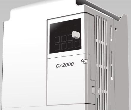
12 1.2 Product Details A Mounting hole B Heat sink C Button cover D Terminal cover E Screw M3 F Front cover G Sheath H Indicator light I -Fan J Fan cover 1-2

13 A Download interface B PNP/NPN select switch C Analog Input V/I select D Control terminal E Power supply terminal F Ground terminal 1-3
14 1.3 Product assembling & disassembling To remove the front cover: Press the both indented sides of the cover lightly and pull up. To change the inverter fan: Press the both sides of bottom cover lightly and pull out to your side. 1-4

15 Chapter 2 INSTALLATION & WIRING 2 INSTALLATION & WIRING 2.1 Installation precautions Handle the inverter with care to prevent damage to the plastic components. Do not hold the inverter by the front cover. It may fall off. Install the inverter in a place where it is immune to vibration or extrusion under allowable temperature (- 10 C~ 50 C) The installation environment of inverter will influence its service life directly, so the inverter shall be used in a condition with standard specification The inverter will be very hot during operation. Install it on a non-combustible surface, far away from hot sources and inflammables. Mount the inverter on a flat, vertical and level surface. Inverter orientation must be vertical. Also leave sufficient clearances around the inverter. Protect from moisture and direct sunlight. 2-1
16 Chapter 2 INSTALLATION & WIRING When two or more inverters are installed, the inverters must be installed in proper positions away from the outlet, whose distance shall be 2mm or more (refer to the following figure) Installed the inverter using screws or bolts to insure the inverter is firmly fastened. Two or more inverters are installed in a location where ambient temperature is over 30 please refer to temperature derating curve in chapter < For installing multiple inverters in a panel > Proper Installation Improper Installation Caution Take caution on proper heat ventilation when arraning control cabinet to form logical air convection to reduce the heat production of the inverter. Proper Installation Improper Installation 2-2
17 Chapter 2 INSTALLATION & WIRING 2.2 External sizes LTVF-C10001BAA LTVF-C10002BAA LTVF-C10003BAA LTVF-C20001BAA LTVF-C20002BAA LTVF-C20003BAA LTVF-C20006BAA LTVF-C40002BAA LTVF-C40003BAA LTVF-C10005BAA LTVF-C10008BAA LTVF-C20010BAA LTVF-C20012BAA LTVF-C40005BAA LTVF-C40007BAA 2-3
18 Chapter 2 INSTALLATION & WIRING LTVF-C10011BAA LTVF-C20018BAA LTVF-C40010BAA LTVF-C20030BAA LTVF-C20040BAA LTVF-C40016BAA LTVF-C40016BAA 2-4
19 Chapter 2 INSTALLATION & WIRING Inverter Power [kw] W [mm] W1 [mm] H [mm] H1 [mm] D [mm] Φ [mm] A [mm] B [mm] Weight [kg] 2-5
20 Chapter 2 INSTALLATION & WIRING 2.3 Terminal wiring Control terminal Name Description 24 24V Output P1 MF input terminal FX: Forward run P2 (Factory setting) RX: Reverse run CM Input signal common P3 EST: Emergency stop MF input terminal P4 RST: Trip reset (Factory setting) P5 JOG: Jog Operation VR 10V power supply for potentiometer AI Freq. Setting voltage signal input: 0~10V Freq. setting current signal input: 0~20mA CM Input signal common AM Multi-function analog out signal: 0~10V 3A Multi-function A contact output 3B relay output B contact output 3C terminal A/B contact common S+ S- RS485 communication terminal SA Safe stop terminal A (and SC, often closed Wiring of power supply terminal (0.1~7.5 KW) SB SC terminals, Inverter displays SAFA when breaking Safe stop terminal B (and SC, often closed terminals, Inverter displays SAFB when breaking Safe stop connection with public power source (24V) 2-6
 S (L2) T (L3) P1 P2 (+) (+) N(-) B U V W * Single phase inverter uses terminal R and T for power input (0.1~2.")
21 Chapter 2 INSTALLATION & WIRING 3 Phase AC Input Input rated voltage DB resistor DC reactor Motor R(L1) S(L2) T(L3) B P1(+) P2(+) N(-) U V W Power Input terminal DB Resistor/ DC reactor N - Motor connection terminal R (L1) S (L2) T (L3) P1 P2 (+) (+) N(-) B U V W * Single phase inverter uses terminal R and T for power input (0.1~2.2KW) 2-7
22 Chapter 2 INSTALLATION & WIRING 2.4 Specifications for power terminal block wiring 0. 1KW- 0. 4KW( si ngl e phase 200V) 0. 75KW- 1. 5KW( si ngl e phase 200V) 2. 2KW( si ngl e phase 200V) R T P1 P2 N R T B P1 P2 N U V W P1 P2 N B U V W R T B U V W 0. 1KW KW( t hree phase 400V) 1. 5KW- 2. 2KW( t hree phase 200V/ 400V) 3. 7kW( t hree phase 200V/ 400V) R S T P1 P2 N R S T B P1 P2 N U V W P1 P2 N B U V W R S T B U V W 5. 5KW- 7. 5KW( t hree phase 200V/ 400V) R S T P1 P2 B N U V W R,S,T Size U,V,W Size Ground Size Terminal Screw Torque mm 2 AWG mm 2 AWG mm 2 AWG Screw Size (Kgf.cm)/lb-in LTVF-C10001BAA M3.5 10/8.7 LTVF-C10002BAA M3.5 10/8.7 LTVF-C10003BAA M3.5 10/8.7 LTVF-C10005BAA M3.5 10/8.7 LTVF-C10008BAA M3.5 10/8.7 LTVF-C10011BAA M4 12.2/10.6 LTVF-C20001BAA M3.5 10/8.7 LTVF-C20002BAA M3.5 10/8.7 LTVF-C20003BAA M3.5 10/8.7 LTVF-C20006BAA M3.5 10/8.7 LTVF-C20010BAA M3.5 10/8.7 LTVF-C20012BAA M3.5 10/8.7 LTVF-C20018BAA M4 12.2/10.6 LTVF-C20030BAA M4 15/13 LTVF-C20040BAA M4 15/13 LTVF-C40002BAA M3.5 10/8.7 LTVF-C40003BAA M3.5 10/8.7 LTVF-C40005BAA M3.5 10/8.7 LTVF-C40007BAA M3.5 10/8.7 LTVF-C40010BAA M4 12.2/10.6 LTVF-C40016BAA M4 13.8/12 LTVF-C40023BAA M4 13.8/12 Strip the sheaths of the wire insulation 7.0mm when a ring terminal is not used for power connection. 2-8
23 Chapter 2 INSTALLATION & WIRING Caution 1Apply the rated torque to terminal screws. Loosen screws can cause of short circuit and malfunction. Tightening the screw too much can damage the terminals and cause short circuit and malfunction. 2Use copper wires only with 600V, 75 ratings for wiring. 3Make sure the input power is off before wiring. 4When power supply is switched off following operation, wait at least 10 minutes after LED keypad display is off before you start working on it. 5Applying input power supply to the output terminals U, V and W causes internal inverter damage. 6Use ring terminals with insulated caps when wiring the input power and motor wiring. 7Do not leave wire fragments inside the inverter. Wire fragments can cause faults, breakdowns and malfunctions. 8When more than one motor is connected to one inverter, total wire length should be less than 150m (492ft). Do not use a 3-wire cable for long distances. Due to increased leakage capacitance between wires, over-current protective feature may operate or equipment connected to the output side may malfunction. In case of long wire length, it should be required to lower carrier frequency or use Micro Surge Filter. 9DC reactor connects with P1 and P2 terminals, if unused, short P1 and P2, otherwise, the inverter will have no power. 10Never short B and P1 terminals or Band P2, Shorting terminals may cause internal inverter damage. 11Do not install a power factor capacitor, surge suppressor or RFI filters in the output side of the inverter. Doing so may damage these components. [Warning] Power supply must be connected to the R, S, and T Terminals. Connecting it to the U, V, W terminals causes internal damages to the inverter. Arranging the phase sequence is not necessary. Motor should be connected to the U, V, and W Terminals. If the forward command (FX) is on, the motor should rotate counter clockwise when viewed from the load side of the motor. If the motor rotates in the reverse, switch the U and V terminals. 2-9
 for 415V drives. Use the dedicated ground terminal to ground the inverter.")
24 Chapter 2 INSTALLATION & WIRING Warning Use the Type 3 grounding method (Ground impedance: Below 100Ω) for 230V drives. Use the Special Type 3 grounding method (Ground impedance: Below 10Ω) for 415V drives. Use the dedicated ground terminal to ground the inverter. Do not use the screw in the case or chassis, etc for grounding. Special ground terminal: Opening to access Note Grounding procedure 1) Remove the front cover. 2) Connect the Grounding wire to the ground terminal and secure the screw tightly. The grounding point shall be close to the inverter as possible as it can, and the grounding wire shall be short as possible as it can Note Grounding work guidance 230V Drives 415 V Drives Inverter capacity Wire Terminal Grounding Terminal Grounding Wire size size screw type screw type 0.1~3.7kW 3.5mm 2 M3 Type mm 2 M3 Special type 3 5.5~7.5kw 5.5mm 2 M4 Type mm 2 M4 Special type
25 Chapter 2 INSTALLATION & WIRING 2.5 Control terminal specification 24 P2 P3 P5 VR AI S+ S- 3A 3B 3C P1 CM P4 AM CM SA SB SC T/M Terminal Description Wire size (mm 2 ) Single Stranded Wire Screw size Torque [Nm] Specification P1 Multi-function input terminal P1-P M2 0.2 P5 CM Common terminal M2 0.2 VR Power supply for analog M2 0.2 Output voltage: 12V Max output current: 10mA Potentiometer:1 ~ 5kohm AI Input voltage:0~10v Analog (voltage and current) input M2 0.2 Input current:0 ~ 20mA Terminal Internal resistance: 250Ω AM Multi-function analog output terminal M2 0.2 Max output voltage: 11[V] Max output current: 10mA S+ RS485 communication terminal M2 0.2 S- RS485 communication terminal M External 24V power supply M2 0.2 Max output current: 100mA 3A Multi-function relay output A M AC 250V, less than 1A 3B Multi-function relay output B M DC 30V, less than 1A 3C Multi-function relay common terminal M SA Safe stop connection terminal A M2 0.2 SB Safe stop connection terminal B M2 0.2 SC Safety power supply (24V) M2 0.2 Note 1) Tie the control wires more than 15cm away from the control terminals. Otherwise, it interferes front cover reinstallation. Note 2) Use Copper wires rated 600V, 75 and higher. Note 3) Use the recommended tightening torque when securing terminal screws. 2-11
26 Chapter 2 INSTALLATION & WIRING Note When you use external power supply (24V) for multi-function input terminal (P1~P5), terminals will be active above 12V level. Take caution not to drop the voltage below 12V. 2.6 PNP/NPN selection and analog input V/I selection P1P5 When using DC 24V inside inverter [NPN] (Inside inverter) P1P5 When using external DC 24V [PNP] (Inside inverter) 2-12
27 Chapter 2 INSTALLATION & WIRING Analog input V/I select keypad J1 switch Selecting analog voltage V input: using external voltage source, J1 switches to V side, connect positive pole of voltage source to terminal AI, and negative pole to terminal CM. Max external voltage: 10V Selecting analog voltage I input: using external current source, J1 switches to I side, connect positive pole of current source to terminal AIand negative to terminal CM. Max external current: 20mA. 2-13


28 Chapter 3 Peripheral equipment 3.1 Peripheral equipment When applying inverter, please select appropriate peripheral equipment and install it correctly. Incorrect configuration and installation may cause system fault and loss of life span. It may even cause damage of inverter. Please carefully read and understand relevant notes of this manual. Apply inverter according to operation regulation. Please apply it within the allowable power AC power range of inverter. 230V V(-15% +10%) 415V V(-15% +10%) MCCB or When supplied with power, inverter may electric leakage produce surging current. Please select breaker breaker carefully. Electromagnetic contactor (optional) AC and DC reactor (optional) Inverter installation and wiring Inverter output side through electromagnetic contactor. Otherwise the operation lifetime of inverter will be shortened. (Electromagnetic contactor is only installed and used under necessary situations) In order to increase power factor or install large capacity system in the surrounding area of inverter, it is necessary to install AC reactor. Please select appropriate reactor according to model of inverter.(more than 10 multiples of inverter capacity. Wring distance is within 10 meters) To make inverter run under highperformance status for a long time, please install inverter at the correct place, leave appropriate space. Incorrect wiring may damage the equipment. Please don't install electric capacity, surging controller or noise filter to output side of inverter. Otherwise, the equipment and inverter will be damaged. 3-1
29 Chapter 3 Peripheral equipment 3.2 Recommend breaker and breaker specification Inverter model Single phase 230V Three phase 230V Three phase 415V L&T MCCB/Amp Electromagnetic contactor LTVF-C10001BAA DM16/2.5 MNX 9-2P LTVF-C10002BAA DM16/6.3 MNX 9-2P LTVF-C10003BAA DM16/12 MNX 9-2P LTVF-C10005BAA DM100/25 MNX 9-2P LTVF-C10008BAA DM100/30 MNX 12-2P LTVF-C10011BAA DM100/50 MNX 18-2P HD ND LTVF-C20001BAA DM16/1.6 DM16/2.5 MO9 LTVF-C20002BAA DM16/4 DM16/4 MO9 LTVF-C20003BAA DM16/4 DM16/7.5 MO9 LTVF-C20006BAA DM16/12 DM16/16 MO9 LTVF-C20010BAA DM16/16 DM100/25 MO-12 LTVF-C20012BAA DM100/25 DM100/25 MO-18 LTVF-C20018BAA DM100/35 DM100/50 MO-32 LTVF-C20030BAA DM100/50 DM100/60 MO-40 LTVF-C20040BAA DM100/60 DM100/80 MO-50 LTVF-C40002BAA DM16/4 DM16/5 MO9 LTVF-C40003BAA DM16/7.5 DM16/10 MO9 LTVF-C40005BAA DM16/10 DM16/12 MO9 LTVF-C40007BAA DM16/12 DM16/16 MO-12 LTVF-C40010BAA DM100/25 DM100/30 MO-18 LTVF-C40016BAA DM100/25 DM100/30 MO-32 LTVF-C40023BAA DM100/30 DM100/50 MO-32 NOTE 1) The current of selected breaker shall be 1.5 to 2 times of rated current. 2) In order to prevent the damage of AC equipment because of fault current, please use MCCB to replace overload protection device (150% rated output 1 minute protection) 3-2
30 Chapter 3 Peripheral equipment 3.3 Recommend fuse and reactor specification Inverter model AC input fuse (external) [Current] [Voltage] AC reactor DC reactor LTVF-C10001BAA 10 A 600 V 1.20 mh, 10A 4mH, 8.67A LTVF-C10002BAA 10 A 600 V 1.20 mh, 10A 4mH, 8.67A Single LTVF-C10003BAA 10 A 600 V 1.20 mh, 10A 4mH, 8.67A phase LTVF-C10005BAA 10 A 600 V 1.20 mh, 10A 4mH, 8.67A 230V LTVF-C10008BAA 15 A 600 V 0.88 mh, 14A 3mH, 13.05A LTVF-C10011BAA 20 A 600 V 0.56 mh, 20A 1.3mH, 18.45A LTVF-C20001BAA 10 A 600 V 1.20 mh, 10A 4mH, 8.67A LTVF-C20002BAA 10 A 600 V 1.20 mh, 10A 4mH, 8.67A LTVF-C20003BAA 10 A 600 V 1.20 mh, 10A 4mH, 8.67A Three LTVF-C20006BAA 10 A 600 V 1.20 mh, 10A 4mH, 8.67A phase LTVF-C20010BAA 15 A 600 V 0.88 mh, 14A 3mH, 13.05A 230V LTVF-C20012BAA 20 A 600 V 0.56 mh, 20A 1.3mH, 18.45A LTVF-C20018BAA 32 A 600 V 0.39 mh, 30A 1.3mH, 26.35A LTVF-C20030BAA 50 A 600 V 0.30 mh, 34A 1.6mH, 32A LTVF-C20040BAA 63 A 600 V 0.22 mh, 45A 1.25mH, 43A LTVF-C40002BAA 10 A 600 V 4.81 mh, 4.8A 16mH, 4.27A LTVF-C40003BAA 10 A 600 V 4.81 mh, 4.8A 16mH, 4.27A Three LTVF-C40005BAA 10 A 600 V 3.23 mh, 7.5A 12mH, 6.41A phase LTVF-C40007BAA 15 A 600 V 2.34 mh, 10A 8mH, 8.9A 415V LTVF-C40010BAA 20 A 600 V 1.22 mh, 15A 5.4mH, 13.2A LTVF-C40016BAA 32 A 600 V 1.12 mh, 19A 3.2mH, 17A LTVF-C40023BAA 35 A 600 V 0.78 mh 27A 2.5mH, 25A 3-3

31 4 Parameter setting 4.1 Keypad structure Display: SET/RUN LED FWD/REV LED 7-segment LED Key RUN STOP/RESET Up/Down Right/Left Enter Display FWD Lit during forward run Blinks when a fault occurs REV Lit during reverse run RUN Lit during operation SET Lit during parameter setting 7-segment Operation data and parameter information are displayed. Keys RUN Run command STOP/RESET STOP: Stop command during operation, RESET: Reset command when fault occurs. Up Used to move parameter codes or increase parameter values Down Used to move parameter codes or increase parameter values Left Used to switch parameter groups or move the cursor to the left when the parameters are written. Right Used to switch parameter groups or move the cursor to the right when the parameters are written. ENT ENT Used to read, write and keep the parameter values. Knob Volume The keypad potentiometer V2 is used for frequency setting.
32 4.2 Alpha-numeric table 0 A K U 1 B L V 2 C M W 3 D N X 4 E O Y 5 F P Z 6 G Q 7 H R 8 I S 9 J T
33 4.3 Moving to other parameter groups LTVF-Cx2000 series product consists of the following four parameter groups. Drive group FU group 1 FU group 2 I/O group Drive Set Basic parameters necessary for inverter operation, including target group frequency, Accel/Decel time and so on. Function Set basic function parameters, such as adjustment of input frequency, group 1 voltage and so on. Function Set advanced function parameters, for example, set application group 2 functions such as PID operation, second motor operation and so on. I/O (input/output) terminal Set multi-function input/ output terminals and analog input/output function group parameters. Moving to other parameter groups Moving to other parameter groups via the Moving to other parameter groups via the Right () key. Left () key. Drive group Drive group I/O group Function group 1 I/O group Function group 1 Function group 2 Function group 2 Note 1) Target frequency can be set at 0.0 (the 1st code of drive group). Even though the preset value is 0.0 while leaving factory, after setting of the target frequency, the changed frequency value will be displayed.
34 Moving to other parameter groups at the 1 st parameter of each group The 1 st code 0.00 in Drive group displayed is displayed after power is applied. -. Press the Right () key once to go to the Function group The 1 st code F0 in Function Group is displayed. -. Press the Right () key once to go to Function group The 1 st code H0 in Function group 2 is displayed. -. Press the Right () key to go to I/O group. -. The 1 st input / output code I 0 is displayed. -. Press the Right () key once to return to Drive group Return to the 1 st code 0.00 of Drive group. If the Left () key is used; the above will be executed in the reverse order. Moving to other parameter groups from any parameter code other than the 1 st code Pressing left or right arrow key in any code of each parameter group can move to the first code of the group. To move from F15 to function group 2 -. F 15 of Function group 1 is displayed Press the Right or Left key to return to the 1 st code of the parameter group. -. The 1 st code F 0 of Function group 1 is displayed Press the Right key.
35 3 -. The 1 st code H 0 of Function group 2 is displayed. 4.4 How to change the codes in a group Code change in Drive group The 1 st code 0.00 of Drive group is displayed. -. Press the Up () key once. -. The 2 nd code ACC of Drive group is displayed. -. Press the Up () key once. -. The 3 rd code dec of Drive group is displayed. -. Keep pressing the Up () key until the last code appears. -. The last code drc of Drive group is displayed. -. Press the Up () key again. Drive group 5 -. Return to the first code of Drive group. Use Down () key for the reverse order. Code jump method When moving from the F 0 to the F 15 in Function parameter group 1 directly -. The 1 st code F 0 of Function group 1 is 1 displayed. -. Press the ENT key is displayed (F1 code), -. Use the Up () key to set to Move the cursor to the left by pressing the Left () key, and 08 is displayed. If the number 0 is displayed brighter than 8, which means 0 is active. -. Use the Up () key to set to has been set, -. Press the ENT key F28 of Function group 1 is displayed. Function group 2 and I/O group are settable with the same method.
36 Navigating codes in the same parameter group When moving from F 1 to F 15 in Function group F1 of Function parameter group 1 is displayed, -. Continue pressing the Up () key until F28 is displayed. -. F28 of Function parameter group 1 is displayed. The same applies to Function group 2 and I/O group. Some codes will be skipped when the Up() or Down () is used, that is because the codes have not been activated due to no use, or some codes intentionally left blank for future use. Refer to the Ch.5 for more specific contents For example, when F24 [High/low frequency limit select] is set to O (No), F25 [High frequency limit] and F26 [Low frequency limit] are not displayed during code change. But When F24 is set to 1(Yes), F25 and F26 will appear on the display.
37 4.5 Parameter setting Parameter setting in Drive group When changing ACC time from 5.0 sec to 16.0 sec ENT ENT ENT Drive group The 1 st code of the parameter group is displayed when the Power is applied -. Press the Up () key. -. The second code ACC of Drive group is displayed. -. Press the ENT key. -. The default code is 5.0 and the cursor is in the digit Press the Left () key once to move the cursor to the left. -. The digit 5 is active, and then the parameter value can be changed. -. Press the Up () key. -. The value is increased to Press the Left () key to move the cursor to the left is displayed. The first 0 in 0.60 is active. -. Press the Up () key once is displayed. -. Press the ENT key is blinking 1) -. Press the ENT key once again to return to the parameter name ACC is displayed. Accel time is changed to Pressing the Left () or Right () key while 16.0 is blinking will disable the setting. Note 1) when the parameter value is changed, the blinking cursor means if any changed value is required, then Press the ENT key to complete the input of parameter change. Press any key of ()()()() if any parameter change is cancelled.
38 Frequency setting When setting run frequency to Hz in Drive group ENT ENT ENT Drive group The 1 st code is displayed when the power is applied. -. Press the ENT key. -. The second decimal 0 becomes active. -. Press the Up () key until 5 is displayed Press the left () key once Move the cursor to the left. -. Press the Left () key once Press the Left () key once Set to 3 using Up () key Press the ENT key is blinking. -. Press the ENT key Set operation frequency to LTVF-Cx2000 product displays 4 digits, but 5 digits can be displayed and set by using Left () key and Right () key. Under the condition that is blinking, pressing any key can cancel the parameter setting except the ENT key.
39 Parameter setting in Function group When changing the parameter value of F28 from 2 to 5 FU group The 1 st code F 0 of Function group 1 is displayed. -. Press the ENT key (F1 code) is displayed -. 8 is set by pressing the Up () key is displayed. -. Press the Left () key once so that the cursor is moved for one digit to the left is active is set by pressing the Up 5 -. Means the current location is for No. 28 parameter of Function group Press the ENT key F28 is displayed. -. Press the ENT key Present value of F28 is set to Increase the value to 5 by pressing Up () key Press the ENT key Parameter number will appear after 5 is blinking. Parameter change is complete. -. Press either Left () or Right () keys Moving to first code of Function group 1 is complete. The above is also applied to parameter setting in function group 2 and I/O group.
40 4.6 Monitoring of operation status Output current display Monitoring output current in Drive group ENT ENT Drive group The 1 st parameter of Drive group is displayed. -. Press the Up () or Down () key until [CUr] is displayed. -. Monitoring output current code is displayed -. Press the ENT key. -. Present output current of inverter is 5 [A]. -. Press the ENT key again Return to the output current monitoring code. The same method is used to monitor dcl (Inverter DC side voltage) or vol (Inverter output voltage) of Drive group and so on.
41 Fault display Monitoring faults in Drive group Overcurrent trip During Accel Current ENT Frequency Drive group STOP RESET -. This message appears when an Over-current fault occurs. -. Press the Enter key or UP ()/Down () key once. -. The run frequency at the time of fault is displayed. -. Press the Up () key once. -. The output current at the time of fault is displayed. -. Press the Up () key once. -. Operating status is displayed. A fault occurred during acceleration. -. Press the STOP/RST key non is displayed after the fault condition is cleared. More than one fault occur at the same time. Motor overheat Over voltage -. Maximum three faults information is displayed as shown left when more than one fault occur at the same time. Over current Drive group
42 Parameter initialize Initializing all the parameters in H93 parameter of Function group 2. ENT ENT ENT ENT The 1 st code of Function group 2 is displayed. -. Press the ENT key once. -. The parameter number 1 to be moved is displayed. -. Increase the value to 3 by pressing the Up () key. -. The parameter number to be moved is 3 -. Press the Left () key once is displayed, and 0 is active. -. Increase the value to 9 by pressing the Up () key. -. The parameter number to be moved is Press the ENT key. -. The present setting is H93 of Function group Press the ENT key. -. The setting value is Press the Up () key once. -. Press the ENT key. Press it again when the number is blinking, then the parameter initialization is active. -. The parameter number is displayed over again. The parameter initialization closes. -. Press the Left () or Right () key Return to the 1 st code H0 of Function group 2.
43 4.7 Frequency setting and Basic Operation Caution The following instructions are given based on the fact that all parameters are set to factory defaults. Results could not be consistent with the following contents if parameter values are changed after purchase of products by customers. In this case, initialize all parameter values and set them according to the instructions below. Frequency setting via key and driving via terminals 1 -. Apply power to the inverter. -. The inverter keypad displays Press the ENT key is displayed and the last 0 is lit Press the Left () key three times is displayed and the leftmost 0 is lit Press the Up () key once is displayed and then press the ENT key is blinking. Press the ENT key again. -. Run frequency is set to Hz when stops blinking Turn OFF (ON) the switch between P1 (FX) terminal and CM terminal on the connection diagram below. -. RUN (operating) lamp on the inverter keypad is blinking, with FWD (Forward Run) indicator light lit and accelerating frequency displayed on the keypad The run frequency reaches 10Hz. -. Turn off the switch between P1 (FX) and CM terminals. -. RUN lamp begins to blink over again and decelerating frequency is displayed on the panel When run frequency is reached to 0Hz, Run (operating) and FWD (Forward Run) lamp is turned off and is displayed on the keypad. Connection diagram Run curve
44 Frequency Setting via Terminal AI (V) and Driving via Terminals 1 -. Apply power to the inverter is displayed on the inverter keypad Press the Up () key four times. -. Freq. is displayed. Frequency setting mode is selectable Press the ENT key. -. Present frequency setting method is set to 0 (frequency setting via keypad) Press the Up () key three times is displayed [frequency setting via terminal AIN (V1)] 5 -. Press the ENT key. -. Press the ENT key again after 3 is blinking. -. Freq. is displayed; the frequency setting method is changed into terminal 6 AIN (V) setting frequency. -. Press the Down () key four times to move to frequency display status. -. V1 voltage is adjusted so that output frequency is Hz. -. Turn off (ON) the switch between P1 (FX) and CM terminals. -. RUN (operating) lamp on the inverter keypad begins to blink with FWD (Forward 7 Run) lamp lit and accelerating frequency displayed on the keypad. -. Run frequency reaches 10 Hz. -. Turn off the switch between P1 (FX) and CM terminals. -. Run (operating) lamp on the inverter keypad is blinking over again, and the number displayed indicates the decelerating frequency After run frequency reaches 0Hz, Run (operating) and FWD (forward run) lamps are blacked out, is displayed on the keypad. Connection diagram Run curve
45 Frequency setting via Terminal AIN (V1) and Driving via Pressing Run Key 1 -. Apply power to the inverter is displayed on the inverter keypad Press the Up () key three times. -. drv. is displayed and the drive pattern is selectable Press the ENT key. -. Present setting value is 1 (operation of inverter terminal) Press the Down () key once. -. Press the ENT key after 0 is displayed Press the ENT key again when 0 is blinking. -. drv is displayed, drive pattern is set via the Run key on the keypad Press the Up () key once. -. Freq. is displayed. Frequency setting method is selectable Press the ENT key. -. Present frequency setting is 0 (frequency setting via keypad) Press the Up () key three times. -. Press the ENT key after 3 is displayed [Terminal AIN (V1)] Press the ENT key over again when 3 is blinking. -. Freq. is displayed; frequency setting method is made via Terminal AIN (V1) Press the Down () key four times to move the frequency display status. -. V1 voltage is adjusted so that output frequency is Hz. -. Press Run key on the inverter keypad. -. Run lamp on the inverter keypad starts to blink with FWD lamp lit and accelerating 11 frequency displayed on the keypad. -. When frequency reaches 10 Hz, press (STOP/RST) key of inverter keypad once. -. RUN (operating) lamp on the inverter keypad blinks over again, with decelerating frequency displayed on the keypad When fun frequency reaches 0Hz, RUN and FWD lamps are blacked out and is displayed on the keypad. Connection diagram Run curve
46 5 Parameter list Drive Group Drive Group Address for comm Parameter name Frequency command Set range [Hz] ACC 1101 Accel time 0.0 Description This parameter sets the frequency that the inverter is commands to output. During stop: frequency command During run: output frequency During Multi-step operation: It cannot be set greater than F21(Max. frequency) During Multi-Accel/Decel operation, this Factory defaults Adj. during run Page 0.00 O O parameter serves as Accel/Decel time dec 1102 Decel time [sec] O 7-12 drv 1103 Drive Mode RUN/STOP via RUN/STOP key on the keypad Terminal operation FX: motor forward run RX: Motor reverse run FX: Run/Stop enable RX: reverse rotation select 1 X 3 RS-485 communication Digital Keypad setting Keypad setting Panel Potentiometer V2 set: 0 ~ 5 [V] 7-2 Frq 1104 Frequency Setting Method Analog Terminal A1 (J1 to V) : 0 ~ +10 [V] Terminal A1 set (J1 to I) :0 ~ 20 [ma] Panel Potentiometer 0 X V2 + Terminal A1 (J1 7-5 to I) setting Panel Potentiometer 6 V2 + Terminal A1 (J1 7-5 to V) setting
47 7 RS-485 communication Digital (UP/DOWN) rotation 8-4 Drive Group Address LED for display comm St St St CUr 1108 rpm 1109 dcl 110A vol 110B non 110C drc 110D drv2 1) 110E Parameter name Multi-step frequency 1 Multi-step frequency 2 Multi-step frequency 3 Output current Motor RPM DC link voltage User display select Fault Display Direction of motor rotation Drive mode 2 Adj. Set Factory Description during range defaults run Page Sets Multi-step frequency 1 during Multistep operation 0.00 O Sets multi-step frequency 2 during multistep operation [Hz] 0.00 O 7-7 Sets multi-step frequency 3 during multistep operation 0.00 O 7-7 [A] Displays the output current to the motor [rpm] Displays the number of Motor RPM [V] - - F, r 0 Displays DC link voltage inside the inverter This parameter displays the item selected at H73- [Monitoring item vol select]. vol Output voltage POr Output power tor Torque Displays the types of faults, frequency and operating status at the time of the fault Direction of motor rotation when drv (Drive mode) is set to 0. F O 7-8 F Forward r Reverse 0 Run/Stop via Run/stop key on the keypad 1 X 8-22
48 3 FX: Motor forward run 1 RX: Motor reverse run Terminal FX: RUN/STOP enable operation 2 RX: Reverse rotation select 3 RS-485 communication 1) : Only displayed when one of the Multi-function input terminals 1-5 [I17~I21] is set to 22. Drive Group LED display Address for commu nication Parameter name Set range Description Factory defaults Adj. during run Page 0 Keypad setting 1 Digital 1 Keypad setting 2 Panel Potentiometer 2 V2 : 0 ~ 5 [V] Terminal A set (J1 to 3 V) Frq2 1) 110F Frequency setting method Analog : 0 ~ +10 [V] Terminal A1 set (J1 TO 1): 0 ~ 20 [ma] 0 X 8-22 Panel Potentiometer 5 V2 +Terminal A1 (J1 to 1) setting Panel potentiometer 6 V2 + Terminal A1 (J1 to V) setting 7 RS-485 communication
49 ref 2) 1110 If H58 is 0, it is expressed as a [Hz] unit PID control If H58 is 1, it is expressed as a standard [%] unit. [Hz] or value In [Hz] unit, you can t set Max. 0 setting Frequency more than (F21). 100[%] In [%] unit, 100% means Max Frequency. Fbk 2) 1111 It indicates a feedback amount in 0.00 PID control. PID control If H58 is 0, it is expressed as a Feedback [Hz] or [Hz] unit. amount 0 If H58 is 1, it is expressed as a 100[%] [%] unit ) : Only displayed when one of the Multi-function input terminals 1-5 [I17~I22] is set to 22. 2) : It is indicated when H49 (PID control selection) is 1. Function group 1 Address Adj. LED Parameter Factory for Range Description During Page display name defaults comm run Sets the parameter code number to F Jump code O 4-5 jump 0 Fwd and rev run enable Forward/reverse F Forward run disable 0 X 7-10 run disable 2 Reverse run disable F Accel pattern 0 Linear Stop mode X 7-15 F S-curve select 0 Decelerate to stop Stop mode 1 DC brake to stop 7-20 F X Select 2 Free run to stop 3 Power Braking stop 8-25 This parameter sets DC brake start 0.10 DC brake frequency. F 8 1) X 8-1 start frequency It cannot be set below Start frequency [Hz] (F23).
50 F When DC brake frequency is reached, DC Brake the inverter holds the output for the wait time [sec] setting time before starting DC brake. This parameter sets the amount of DC F10 120A DC brake 0 voltage applied to a motor. Voltage 200[%] It is set in percent of Motor rated current (H33). F11 120B 0.0 The parameter sets the time taken to DC brake 60.0 apply DC current to a motor while Time [sec] motor is at a stop. This parameter sets the amount of DC F12 120C Brake start 0 voltage before a motor starts to run. voltage 200[%] It is set in percent of Motor rated current (H33). F13 120D 0.0 DC voltage is applied to the motor for DC brake 60.0 DC brake start time before motor start time [sec] accelerates. 1) : Only displayed when F4 (DC brake stop) is set to X 50 X 1.0 X 50 X 0.0 X 8-2 Function group 1 LED display Address for comm Parameter name Range Description Factory defaults Adj. During run Page F14 120E Time for magnetizing a motor [sec] This parameter applies the current to a motor for the set time before motor accelerates during sensorless vector control 0.5 X 8-15 F Jog frequency [Hz] This parameter sets the frequency for jog operation. It cannot be set above max frequency (F21) O 8-3 Highest frequency the inverter can F21 1) 1215 Max frequency [Hz] output. It is frequency reference for Accel/Decel (See H70) X 7-21 Caution
51 F Base frequency F Start frequency Frequency F high/low limit select F25 2) 1219 Frequency high limit F26 121A Frequency Low limit Except F22 (base frequency), any frequency which is set above F21 will automatically turn to the set value of F The inverter outputs its rated voltage to the motor at this frequency (see [Hz] motor nameplate) The inverter starts to output its 0.10 voltage at 10.00[Hz This frequency. It is the frequency low ] limit. This parameter sets high and low limit 0 1 of run frequency This parameter sets high limit of the 0.00 run frequency It cannot be set above Max frequency [Hz] (F21). This parameter sets low limit of the 0.00 run frequency It cannot be set above Frequency [Hz] high limit (F25) and below Start frequency (F23). 1) : If H40 is set to 3 (sensorless vector), Max frequency is settable up to 120Hz X X X X X 2) : Only displayed when F24 (Frequency high/low limit select) is set to 1. Function group 1 LED display Address for comm Parameter name Range Description Factory defaults Adj. During run Page F27 121B Torque boost select Manual torque boost 0 X 1 Auto torque boost F28 121C Torque boost in forward direction [%] This parameter sets the amount of torque boost applied to a motor during forward run. It is set in percent of Max output voltage. 3.0 X 7-19
52 F29 121D Torque boost in reverse direction [%] F30 121E V/F pattern 0 2 F31 1) 121F User V/F frequency 1 F User V/F voltage [Hz] [%] This parameter sets the amount of torque boost applied to a motor during reverse run. It is set as a percent of Max output voltage 3.0 X 0Linear Square 0 X User V/F F User V/F frequency 2 [Hz] F User V/F 0 voltage [%] F User V/F frequency 3 [Hz] F User V/F 0 voltage [%] F User V/F frequency 4 [Hz] F User V/F 0 voltage [%] 1) : Set F30 to 2(User V/F) to display this parameter It is used only when V/F pattern is set to 2 user/v/f). It cannot be set above F21- Max frequency. The value of voltage is set in percent of motor rated voltage. The values of lower-numbered parameters cannot be set above those of higher-numbered X 7-18
53 Function group 1 LED display Address for comm Parameter name Range Description Factory defaults Adj. During run Page F Output voltage adjustment [%] This parameter adjusts the amount of output voltage. The set value is the percentage of input voltage X 7-18 F Energy-saving level 0 30[%] This parameter decreases output voltage according to load status F Electronic thermal select 0 1 This parameter is activated when the motor is overheated (time-inverse) This parameter sets max current capable of flowing to the motor F51 1) 1233 Electronic thermal level for 1 minute [%] continuously for 1 minute. The set value is the percentage of Motor rated current (H33) It cannot be set below Electronic thermal level for continuous (F52). This parameter sets the amount of F Electronic thermal level for continuous [%] current to keep the motor running continuously. It cannot be set higher than Electronic thermal level for 1 minute (F51). Standard motor having cooling F Motor cooling method fan directly connected to the shaft 0 0 A motor using a separate motor to power a cooling fan. This parameter sets the amount of current to issue an alarm signal at a F Overload warning level [%] relay or multifunction output terminal (see I55) The set value is the percentage of Motor rated current (H33).
54 1) : Set F50 to 1 to display this parameter. Function group 1 LED display Address for comm Parameter name Range Description Factory defaults Adj. During run Page F Overload warning time [Sec] This parameter issues an alarm signal when the current greater than Overload warning level (F54) flows to the motor for Overload warning time (F55) F Overload trip select 0 1 This parameter turns off the inverter output when motor is overloaded. 1 0 This parameter sets the amount of overload F Overload trip level [%] current. The value is the percentage of Motor rated current (H33). F58 123A Overload trip time [Sec] This parameter turns off the inverter output when the F57- [Overload trip level] of current flows to the motor for Overload trip time (F58) This parameter stops accelerating during acceleration, decelerating during constant speed run and stops decelerating during deceleration. During During During Decel constant run Accel Stall Bit 2 Bit 1 Bit 0 F59 123B prevention select X
55 F60 123C Function group 1 LED display F61 1) F63 Address for comm 123D 123F F64 2) 1240 F F F67 3) 1243 Stall prevention level Parameter name When Stall prevention during deceleration, voltage limit select Save up/down frequency select Save up/down frequency [%] Range Up-down Mode select 0 2 Up-Down step frequency 200V input voltage [Hz] [V] This parameter sets the amount of current to activate stall prevention function during Accel, Constant or Decel run. The set value is the percentage of Motor rated current (H33). 150 X 10-3 Description Adj. Factory During defaults run Page In Stall prevention run during deceleration, if you want to limit output voltage, select 1 0 X 8-25 This parameter decides whether to save the specified frequency during up/down operation. When 1 is selected, the up/down frequency is 0 X 8-4 saved in F64. If Save up/down frequency is selected at F63, this parameter saves the frequency before the 0.00 X 8-4 inverter stops or decelerated. We can select up-down mode among three thing Increases goal frequency as a 0 standard of Max. frequency/min. frequency 0 X Increases step frequency 66 according to edge input F Available to combine 0 and 1 In case of choosing F65 as a 1 or 2, it means increase or decrease of frequency according 0.00 X 8-5 to up-down input. 200V inverter input voltage set
56 400V input 320 F68 3) V inverter input voltage set voltage 480[V] 1) : It is indicated when setting bit 2 of F59 as 1 2) : Set F63 to 1 to display this parameter. 3) : 200V inverter displays F67, 400V inverter displays F68. Function group 1 Address Adj. LED Parameter Factory for Range Description During Page display name defaults comm run 0 Inverter doesn t run as a draw mode 1 Analog terminal AI V terminal (0-10 V) F input drawn run Draw run Analog terminal AIV terminal (0-20 V) mode select input drawn run 0 X Panel potentiometer V2 (0-5V) input draw run F Draw rate 0 Set rate of draw 100[%] 0.0 O 8-27 F72 2) 1248 F73 1) 1249 F74 1) 124A ND/HD 0: HD (CT) heavy load X 8-22 selection 1: ND (VT) light load 200V DB 300 Set DB start voltage of 200V class inverter start voltage 400[V] 400V DB 600 Set DB start voltage of 400V class inverter start voltage 800[V] 1) : 200V inverter displays F73, 400V inverter displays F74. 2) : only HD selection for single phase 200V inverter Function group 2 Address LED Parameter Factory for Range Description display name defaults comm Adj. During Page run H Jump code 0 95 Sets the code number to jump. 1 O 4-5 H Fault history 1 - Stores information on the types of faults, non - H Fault history 2 - the frequency, the current and the non H Fault history 3 - Accel/Decel condition at the time of fault. non - H Fault history 4 - The latest fault is automatically stored in non -
57 H Fault history 5 - Fault history 1. non - H H H H10 130A H11 1) 130B H12 130C H13 130D H14 130E H15 130F H Reset fault history 0 1 Clears the fault history saved in H O When run frequency is issued, motor starts 0.10 Dwell frequency [Hz] 0.0 Dwell 10.0 time [sec] Skip frequency 0 1 select Skip frequency low limit 1 Skip frequency high limit 1 Skip frequency 0.10 low limit Skip frequency [sec] high limit 2 Skip frequency low limit 3 Skip frequency high limit 3 1) : only displayed when H10 is set to 1. to accelerate after dwell frequency is applied to the motor during Dwell time (H8). Dwell frequency can be set within the range of Max frequency (F21) and Start frequency (F23) X Sets the time for dwell operation. 0.0 X Sets the frequency range to skip to prevent undesirable resonance and vibration on the 0 X structure of the machine X Run frequency cannot be set within the range of H11 thru H16. The frequency values of the low numbered parameters cannot be set above those of the high numbered ones. Settable within the range of F21 and F X X X X X Function group 2 LED display Address for comm Parameter name Range Description Factory defaults Adj. During run Page H S-Curve accel/decal start side 1 100[%] Set the speed reference value to form a curve at the start during accel/decel. If it is set higher, linear zone gets smaller. 40 X 7-15
58 H S-Curve Set the speed reference value to form a 1 accel/decal curve at the end during accel/decel. If it is 100[%] end side set higher, linear zone gets smaller. Input/output Inverter input output lack phase H phase loss protection selection 0 3 protection Bit0: inverter output lack phase selection select Bit1: inverter input lack phase selection This parameter is activated when drv is H set to 1 or 2 (Run/Stop via Control Power On 0 1 terminal). Motor starts acceleration after Start select AC power is applied while FX or RX terminal is ON. This parameter is activated when drv is H set to 1 or 2 (Run/Stop via Control Restart after terminal). fault reset 0 1 Motor accelerates after the fault condition selection is reset while the FX or RX terminal is ON. # H17, H18 are used when F2, F3 are set to 1 (S-curve). 40 X 3 O O O 7-11
59 Function group 2 Address LED for display comm H22 1) 1316 Parameter name Range Description This parameter is active to prevent any possible fault when the inverter outputs its voltage to the running motor. Power Restart On start after Norm Operation instant al after fault power accel failure bit 3 bit 2 bit 1 bit Speed Search Select Factory defaults Adj. During Page run 0 X ) : H22 Normal acceleration has first priority. It has no relation with others. In acceleration, speed tracking works.
60 Function group 2 Address LED for display comm H H H Parameter name Range Current level 80 During Speed 200[%] search P gain during 0 Speed search 9999 I gain during 0 Speed search 9999 Number of Auto H26 131A 0 10 Restart try H27 131B Auto restart 0 time 60[sec] H30 131E 0.1 Motor type select 11.0 H31 131F H H Number of 2 12 motor poles 0.00 Rated slip frequency [Hz] Motor rated 0.1 current 150.0[A] 1) : H30 is preset based on inverter rating. Description This parameter limits the amount of current during speed search. The set value is the percentage of Motor rated current (H33). It is the Proportional gain used for Speed Search PI controller. It is the Integral gain used for Speed search PI controller. This parameter sets the number of restart tries after a fault occurs. Auto Restart is deactivated if the fault outnumbers the restart tries. This function is active when [drv] is set to 1 or 2 {Run/Stop via control terminal}. Deactivated during active protection function (OHT, LVT, EXT, HWT etc.). This parameter sets the time between restart tries kW kW This setting accords to nameplate of motor. Motor nameplate rated rotation speed conversion is frequency. The difference between input power frequency and this value. Enter motor rated current on the nameplate. Adj. Factory During Page defaults run 150 O O 200 O 0 O O ) X X ) X X 2) : H32 ~ H36 factory default values are set based on 200V/400V HIGEN motor.
61 Function group 2 Address LED for display comm H H H H H H H42 132A H44 132C Parameter Factory Range Description name defaults Enter the current value detected when the motor is rotating in rated rpm after the Adj. During Page run No load 0.1 load connected to the motor shaft is motor current 100.0[A] removed. Enter the 50% of the rated 0.7 X 8-15 current value when it is difficult to measure no Load Motor Current. Motor 50 Enter the motor efficiency (see motor efficiency 100[%] nameplate). 72 X - Select one of the following according to Load motor inertia. inertia Less than 10 times 0 X 8-1 rate 1 About 10 times 2 More than 10 times This parameter affects the audible sound of the motor, noise emission from the 5.0 1) inverter, inverter temp, and leakage Carrier current. If the set value is higher, the frequency [khz] inverter sound is quieter but the noise O 8-20 from the inverter and leakage current will 3.0 1) become greater. 0 V/F Control} 7-17 Control mode 1 Slip compensation control X select 2 3 Sensorless vector control 8-15 If this parameter is set to 1, it Auto 0 1 automatically measures parameters of tuning H42 and H44. 0 X Stator This is the value of the motor stator resistance (Rs) [ ] resistance. - X Leakage This is leakage inductance of the stator inductance (L ) and rotor of the motor. [mh] - X 1) :Default carrier frequency of 0.1~3.7KW series is 5KHzand default value of KW series is 3 KHz.
62 Function group 2 LED display H45 1) H46 H47 Address Adj. Factory for Parameter name Range Description During Page defaults comm run 132D 132E 132F H Sensorless P gain 0 P gain for Sensorless control 1000 O Sensorless l gain I gain for Sensorless control 100 O - Sensorless Limits output torque in sensorless Torque limit 220.0[%] mode X If you want to limit a inverter leakage current, select 2 phase PWM mode. It PWM mode has more noise in comparison to 0 1 select normal PWM mode. 0 X Normal PWM mode 1 2 phase PWM mode H PID select 0 1 Selects whether using PID control or not 0 X Analog input terminal AI (I :0 ~ 20 ma) H50 2) 1332 PID F/B select 0 2 Analog input terminal AI 0 X 1 (V :0 ~ 10 V) 2 RS-485 communication 0.0 H P gain for PID O [%] 8-10 H Integral time for This parameter sets the gains for the PID PID controller. [sec] 1.00 O H Differential time for PID (D gain) [sec] 0.00 O Selects PID control mode PID control H Normal PID control 0 X 8-10 mode select 1 Process PID control 1) : Set H40 to 3 (Sensorless vector control) to display this parameter. 2) : Set H49 to 1 (PID control) to display this parameter.
63 Function group 2 Address Adj. LED Factory for Parameter name Range Description During display defaults comm run PID output 0.10 This parameter limits the amount of the H55 1) 1337 frequency O output frequency through the PID control. high limit] [Hz] The value is settable within the range of PID output 0.10 Max frequency (F21) and Start frequency H frequency O (F23). low limit [Hz] Selects PID standard value. Standard value is indicated in ref of Drive group. H PID 0 0 Loader digital setting 1 standard 1 Loader digital setting 2 value select 4 2 V1 terminal setting : 0~10V 0 X 3 I terminal setting: 0~20mA 4 Setting as a RS-485 communication Selects a unit of the standard value or 0 PID control feedback amount. H58 133A 0 X unit select 0 Frequency [Hz] 1 1 Percentage [%] 0.0 H61 133D Sleep delay time Sets a sleep delay time in PID drive X [sec] H62 133E Sleep frequency Sets a sleep frequency when executing a 0.00 sleep function in PID control drive You can t set more than Max. frequency [Hz] (F21) 0.00 O H63 133F Wake up level 0.0 Sets a wake up level in PID control drive [%] 35.0 O H KEB drive select 0 1 Sets KEB drive. 0 X KEB action Sets KEB action start level according to H65 2) X start level 140.0[%] level. 1) : Set H49 to 1 (PID control) to display this parameter. Page ) : It is indicated when setting H64 to 1.# KEB does not operate when cut power after loading ting input (about 10% ). Function group 2
64 Address LED for display comm H66 1) 1342 H H H H Parameter Factory Range Description name defaults Adj. During Page run KEB action Sets KEB action stop level according to X stop level 145.0[%] level. KEB action 1 Sets KEB action gain. 50 X gain Frequency 0 Based on Max freq (F21) reference for X 7-12 accel/decel 1 Based on Delta freq. 0 Settable unit: 0.01 second. Accel/Decel Settable unit: 0.1 second. time scale 2 Settable unit: 1 second. 1 O 7-12 This parameter selects the parameter to be displayed on the keypad when the input power is first applied. 0 Frequency command 1 Accel time 2 Decel time 3 Drive mode 4 Frequency mode 5 Multi-Step frequency 1 6 Multi-Step frequency 2 Power on Multi-Step frequency 3 display 8 Output current 0 O Motor rpm 10 Inverter DC link voltage 11 User display select (H73) 12 Fault display 13 Direction of motor rotation select 14 Output current 2 15 Motor rpm 2 16 Inverter DC link voltage 2 17 User display select 2 (H73 set) 1) : It is indicated when setting H64 to 1.# KEB does not operate when cut power after loading ting input (about 10% ). Function group 2
65 Address LED for display comm H H74 134A H75 134B H76 134C H77 1) 134D H78 134E H79 134F Parameter Factory Range Description name defaults One of the following can be monitored via Adj. During Page run vol(user display select). Monitoring Output voltage [V] item select 1 Output power [kw] 0 O Torque [kgf m] Gain for This parameter is used to change the motor 1 Motor rpm rotating speed (r/min) to mechanical speed 1000[%] display (m/mi) and display it. DB resistor 0 Unlimited operating 0 1 rate limit 1 Use DB resistor for the rate set in H76. select DB resistor Set the percent of DB resistor operating rate 0 30 operating to be activated during one sequence of [%] rate operation. 0 Cooling fan is always on Keeps ON when its temp is higher than Cooling inverter protection limit temp. 0 1 fan control 1 Activated only during operation when its temp is below that of inverter protection limit. Operating Continuous operation when cooling fan 0 method malfunctions. select when 0 1 Operation stopped when cooling fan cooling fan 1 malfunctions. malfunctions 100 O O O 0 O O 8-29 S/W This parameter displays the inverter software X.X X.X X version version. 1) : Single phase 0.1/0.2kW, three phase 200V 0.1/0.2/0.4KW and three phase 400V 0.4KW are NO FAN TYPE, so this parameter has no displaying. Function group 2
66 Address LED Parameter for display name comm Range Description H81 1) nd motor 0.0 Accel time H nd motor [sec] Decel time H nd motor base This parameter actives when frequency [Hz] the selected terminal is ON H nd motor 0 2 after I17-I24 is set to 12 {2nd V/F pattern motor select}. H nd motor forward Torque boost [%] H nd motor reverse Torque boost H nd motor Stall 30 ~ 150 Multi-function terminal (1 17- prevention level [%] 121). When one set is 12 H nd motor (No 2 motor selects), switch 50 ~ 200 Electronic thermal on the terminal. No. 2 motor [%] level for 1 min parameter activates. 2nd motor H Electronic thermal 50 ~ 150 level for [%] continuous H90 135A 2nd motor rated 0.1 ~ current 100.0[A] 1) : It is indicated when choosing I17~I21 as a 12 (2nd motor select). Adj. Factory During defaults run 5.0 O 10.0 O X 0 X 5.0 X 5.0 X 150 X 150 O 100 O 1.8 X Page
67 Function group 2 LED display Address for comm Parameter name Range Description Factory defaults Adj. During run Page This parameter is used to initialize parameters back to the factory default value. 0 - H93 135D Parameter initialize 0 ~ 5 1 All parameter groups are initialized to factory default value. 0 X Only Drive group is initialized. 3 Only Function group 1 is initialized. 4 Only Function group 2 is initialized. 5 Only I/O group is initialized. H94 135E Password register 0 ~ FFFF Password for H95-[Parameter lock]. Set as Hexa value. 0 O 8-31 This parameter is able to lock or unlock parameters by typing password H95 135F Parameter lock 0 ~ FFFF registered in H94. UL Parameter change enable (Unlock) 0 X 8-32 L (Lock) Parameter change disable
68 Input/output group LED display Address for comm Parameter name Range Description Factory defaults Adj. During run Page I Jump code 0 87 Sets the code number to jump. 1 O 4-5 I I I I I I I I I I10 140A V2 input wave 0 Set panel potentiometer V2 input filtering filtering time 9999 wave time constant constant 10 O V2 input Min 0.00 voltage Sets Min. voltage of V2 input. 5.00[V] 0.00 O V2 input Min 0.00 voltage Sets the inverter output min. frequency at corresponding min. voltage of panel potentiometer input. [Hz] frequency 0.00 O V2 input 0.00 Sets the maximum voltage of panel Max voltage] 5.00[V] potentiometer V O V2 input Max voltage Sets the panel potentiometer V2 Max corresponding input voltage, corresponding frequency. [Hz] frequency O Filter time 0 Sets simulation input A1 (terminal V) input constant for 9999 filtering wave time constant. V1 input 10 O V1 input Min 0.00 voltage Sets the minimum voltage of the V1 Input [V] 0.00 O V1 input Min 0.00 voltage Sets simulation input A1 (terminal V) min corresponding input voltage, corresponding frequency. [Hz] frequency 0.00 O V1 input Max 0.00 Sets simulation input A1 (terminal V) Max. voltage 10.00[V] input voltage O V1 input Max. voltage corresponding frequency 0.00 Sets simulation input A1 (Terminal V) Max input voltage, corresponding frequency. [Hz] O
69 Input/output group LED display Address for comm Parameter name I11 140B I input I12 140C I input Min current 1 input Min. I13 140D current corresponding frequency I14 140E I input Max current 1 input Max. I15 140F current corresponding frequency Criteria for I Analog Input Signal loss Range [ma] [Hz] [ma] [Hz] 0 2 Description Sets simulation input A1 (terminal 1) input filtering wave time constant. Sets simulation input A1 (terminal 1) Min. input current Sets simulation input A1 (terminal 1) Max. Factory defaults 10 O 4.00 O Adj. During Page run input current, corresponding frequency O 7-3 Sets the Maximum current of I input O Sets simulation input A1 (terminal 1) Max. input current, corresponding frequency O 0: Disabled 1: activated below half of set value. 0 O : activated below set value.
70 Input/output group LED display Address for comm Parameter name Range Description Factory defaults Adj. During run Page I Multi-function input terminal P1 define 0 Forward run command 1 Reverse run command 0 O 7-8 I Multi-function input terminal P2 define 2 Emergency Stop Trip 3 Reset when a fault occurs 1 O I Multi-function input terminal P3 define 4 Jog operation command 5 Multi-Step freq Low 2 O 8-3 I Multi-function input terminal P4 define 6 Multi-Step freq Mid 7 Multi-Step freq High 3 O 7-7 I Multi-function input terminal P5 define 8 Multi Accel/Decel Low 9 Multi Accel/Decel Mid 1 Multi Accel/Decel High 0 4 O DC brake during stop nd motor select Reserved Reserved- 1 Frequency increase 5 Up- 1 Down command (UP) Frequency decrease command (DOWN) wire operation External trip: A Contact (EtA) External trip: B Contact (EtB) Reserved- -
71 2 Change from PID operation to V/F operation 2 2nd Source Analog Hold Accel/Decel Disable Up/Down save freq Initialization 8-3 # In I17-I21, please refer to Chapter 6 for fault signal input displaying. # Two or above multi-function input terminal cannot be set, which has the same function. Input/output group 2 6 JOG-FX 2 7 JOG-RX Address LED for display comm I I26 141A I27 141B I30 141E I31 141F I Adj. Parameter Factory Range Description During Page name defaults run Input terminal status display Output terminal status display Filtering time Constant for Multifunction Input terminal Multi-Step frequency 4 Multi-Step frequency 5 Multi-Step frequency 6 BIT 4 BIT 3 BIT 2 BIT 1 BIT P5 P4 P3 P2 P1 BIT AC 1 If the value is set higher, the responsiveness of the Input terminal is 15 getting slower It cannot be set greater than F21 [Max frequency]. [Hz] 4 O O 0.00 O O
72 I Multi-Step frequency O I Multi-Accel time O I Multi-Decel time O I Multi-Accel time O I Multi-Decel time O I Multi-Accel time O I Multi-Decel time O 0.0 I Multi-Accel time O I Multi-Decel time O [sec] I42 142A Multi-Accel time O I43 142B Multi-Decel time O I44 142C Multi-Accel time O I45 142D Multi-Decel Time O I46 142E Multi-Accel time O I47 142F Multi-Decel time O 7-14 Input/output group LED display Address for comm Parameter name Range Description Factory defaults Adj. During run Page Output item Output to 10[V] 200V 400V I Analog output item select Output freq. Max frequency 150% inverter rated 1 Output current current 0 O Output voltage AC 282V AC 564V 3 DC link voltage DC 410V DC 820V I Analog output level adjustment [%] Based on 10V 100 O 9-5 I I Frequency detection level 0.00 Frequency detection [Hz] Used when I54 or I55 is set to 0-4. Cannot be set higher than F O O 9-7 bandwidth
73 Input/output group Adj. LED Address for Parameter Factory Range Description During Page display comm name defaults run 0 FDT FDT-2 2 FDT FDT-4 4 FDT Overload (OL) 6 Inverter Overload (IOL) 7 Motor stall (STALL) I Multi 0 -function relay 19 select Fault 0 I Relay output 7 8 Over voltage trip (Ovt) 9 Low voltage trip (Lvt) 10 Inverter Overheat (OHt) 11 Command loss 12 During Run 13 During Stop 14 During constant run 15 During speed searching 16 Wait time for run signal input 17 Multi-function relay select 18 Warning for cooling fan trip 19 Brake signal select When setting Number of auto restart try (H26) When the trip other than low voltage trip occurs When the low voltage trip occurs bit 2 bit 1 bit
74 Input/output group Adj. LED Address for Parameter Factory Range Description During display comm name defaults run Page I59 143B Communic Set communication protocol. 0 ation protocol 0 Modbus RTU 1 select 0 X 11-2 I60 143C Inverter 1 number 250 Set for RS485 communication 1 O 11-2 Set communication speed [bps] [bps] I61 143D Baud rate [bps] 3 O [bps] [bps] [bps] It is used when freq command is given via AI Drive mode terminal or RS485. Select after 0 Continuous operation at the frequency I62 143E loss of 0 0 O 10-7 before its command is lost. frequency 2 1 Free Run stop (Output cut-off) command 2 Decel to stop I63 143F Wait time This is the time inverter determines whether 0.10 after loss there is the input frequency command or of not. If there is no frequency command input frequency during this time, inverter starts operation via [sec] command the mode selected at I O 10-7 Communic 2 I ation time 100 Frame communication time 5 O 11-2 setting [ms] When the protocol is set, the communication format can be set. I Parity/stop 0 0 Parity: None, Stop Bit: 1 bit setting 3 1 Parity: None, Stop Bit: 2 0 O Parity: Even, Stop Bit: 1 3 Parity: Odd, Stop Bit: 1
75 Input/output group LED display Address for communica tion Parameter name Range Description Factory defaults Adj. During run Page Read I address 5 register 1 Read I address 6 register 2 Read I address 7 register 3 Read I I address register 4 Read address The user can register up to 8 discontinuous addresses and read them all with one Read command register 5 Read I address 10 register 6 Read I address 11 register 7 Read I address 12 register 8 Write I74 144A address 5 register 1 I75 144B Write address register The user can register up to 8 discontinuous addresses and write them all with one Write command Write 7 I76 144C address register 3
76 Input/output group Address for LED communica display tion I77 144D I78 144E I79 144F I I I82 1) 1452 I I I I I Adj. Parameter Factory Range Description During Page name defaults run Write The user can register up to 8 8 address discontinuous addresses and write register 4 them all with one Write command Write 5 address register 5 Write 0 6 address register Write 7 address register 7 Write 8 address register Brake open current [%] Brake open 0.00 delay time 10.00[sec] Brake open 0.00 FX frequency [Hz] Brake 0.00 open RX frequency [Hz] Brake 0.00 close delay 10.00[sec] time Brake 0.00 close frequency [Hz] 1) : It is indicated when choosing I54~I55 as a 19 (Brake signal). Sets current level to open the brake. It is set according to H33 s (motor rated current) size 50.0 O Sets Brake open delay time X Sets FX frequency to open the brake 1.00 X 8-26 Sets RX frequency to open the brake 1.00 X Sets delay time to close the brake 1.00 X Sets frequency to close the brake 2.00 X
77 6. Control Block Diagram Frequency Setting D rive m ode A ccel/d ecel V/F C ontrol PW M M otor
78 6.1 Frequency Setting 1st R eference Frequency 2nd R eference Frequency M ulti-step Frequency JO G Frequency M ulti-function Input M ulti-function Input M ulti-function Input I/O Group I/O Group I/O Group I17~I21 I17~I21 I17~I21 1st Reference Frequency 2nd Reference Freq. Select M ulti-step Select 1. JO G Select 2. JO G _FX Select 3. JO G _R X Select Final Reference Freq.
79 K eypad V2 0 ~ +5 [V] V1 0 ~ +10 [V] I 0 ~ 20 [m A] D igital C om m unication K eypad V2 0 ~ +5 [V] V1 0 ~ +10 [V] I 0 ~ 20 [m A] C om m unication Analog Input Filter I/O Group I 1, 6, 11 Analog Input Filter I/O Group I 1, 6, 11 Analog Input Scale I/O Group I 2 ~ I15 Analog Input Scale I/O Group I 2 ~ I15 1st Freq. Select DRV Group Frq Keypad Setting 1 0 Keypad Setting 1 V2 : 0 ~ 5 V 2 V1 : 0 ~ 10V 3 I : 0 ~ 20m A 4 V2 + I 5 V2 + V1 6 C om m unication 7 8 Up Down Operation 2nd Freq. Select DRV Group Frq Keypad Setting 1 0 Keypad Setting 2 1 V2 : 0 ~ 5 V 2 V1 : 0 ~ 10V 3 I : 0 ~ 20m A 4 V2 + I 5 V2 + V1 6 C om m unication 7 1st R eference Freq. D igital Input Filter I/O Group P 1 I 27 P 2 P 3 P 4 P 5 2nd R eference Freq. M ulti-step Operation Select I/O Group I17 ~ I21 5,6,7 M ulti-step Freq. Select DRV Group S t1 S t2 S t3 I/O Group I30 I31 I32 I33 M ulti-step Freq.
80 6.2 Drive command setting P1 P2 P3 P4 P5 D igital Input Filter I/ O G roup I 27 Forw ard/r everse C om m and Select 3 W ire O peration I/ O Group I/ O Group I17 ~ I24 I17 ~ I21 0,1 17 Keypad 0 1,2 3 Com m unication D rive C om m and Select Drive Group drv Forw ard/reverse R un D isable Func. Group 1 F 1 0 FWD/REV Run 1 FWD Disable 2 REV Disable D rive C om m and
81 6.3 Accel/Decel setting and VF control P1 P2 P3 P4 P5 Digital input filter I/O group I27 A ccel/d ecel tim e Max freq. Drive group A C C D EC FU group 1 F21 R eference freq. for Accel/Decel FU group 2 P1 ~ P8 H M ulti-accel/d ecel time select I/O group I17 ~ I21 1st-7th Accel/ D eceltim e I/O group I34 ~ I47 1 ~ 7 Frequency setting 5,6,7 FU group 1 V/F pattern FU group 1 User V /F Voltage Freq. Linear Square User V/F F FU group 1 F31~F38 Torque boost value FU group 1 M anual Torque boost Select FU group 1 0 F27 F28 F29 Autom atic 1 R un com m and Accel/D ecel pattern FU group 1 F2, F3 0 Linear 1 S-curve 0 Shortest time 1 Optimal time + Dwell freq.& time Freq. high/low limit FU group 2 DC brake voltage&time H 7 FU group 1 FU group 1 H 8 F25 F8 ~ F11 Dwell Operation F26 DC brake start freq. O peration Stop Stop method select FU group 1 D C brake freq. voltage time 0 F4 FU group 1 F8 ~ F11 DC brake 1 2 Free Run Stop Output voltage adjustm ent Base/Start freq. FU group 1 FU group 1 F39 F22 PW M F23
82 Chapter 7 Basic Functions 7. Basic Functions 7.1 Frequency setting method Keypad frequency setting 1 Group Code Item Set value Range Initial Unit Drive group 0.00 Target frequency ~ Hz Frq Frequency setting mode 0 0 ~ 8 0 Set Frq code of Drive group to 0. In the frequency command code (0.00), after setting of the operating frequency, press the Ent() key to complete the frequency change. The set value shall not exceed the maximum frequency (F21). When remote keypad is connected, keypad keys on the body are deactivated but controlled by the button on the remote keypad. Keypad frequency setting 2 Group Code Item Set value Range Initial Unit Drive group 0.00 Target frequency ~ Hz Frq Frequency setting mode 1 0 ~ 8 0 Set Frq code of Drive group to 1. When the operating frequencies are set in the frequency command code of Drive group, press Up()/Down() key for frequency change. Take Up/Down key as a potentiometer with the same functions. The set value shall not exceed the maximum frequency (F21). When remote keypad is connected, keypad keys on the body are deactivated but controlled by the button on the remote keypad.
83 Chapter 7 Basic Functions Setting frequency for keypad potentiometer V2: 05 [V] Group Code Item Set value Range Initial Unit Drive group 0.00 Target frequency ~ Hz I/O group Frq Frequency setting mode 2 0 ~ 8 0 I 1 Filter time constant for V2 input - 0 ~ I 2 V2 input Min voltage ~ V I 3 Corresponding frequency for V2 input Min Voltage ~ Hz I 4 V2 input Max voltage ~ V I 5 Corresponding frequency for V2 input Max voltage ~ Hz Set Frq code of Drive group to 2. Use the knob setting frequency on the keypad. Monitor the frequency value set in the target frequency (0.00) of Drive group. Terminal AI setting frequency(dial J1 to V terminal): input 0 +10[V] Group Code Item Set value Range Initial Unit Drive group 0.00 Target frequency ~ Hz I/O group Frq Frequency setting mode 3 0 ~ 8 0 I 6 Filter time constant for V1 input - 0 ~ I 7 V1 input Min voltage ~ V I 8 Corresponding frequency for V1 input Min voltage ~ Hz I 9 V1 input Max voltage ~ V I 10 Corresponding frequency for V1 input Max voltage ~ Hz Set Frq code of Drive group to 3. Monitor the frequency setting value in the target frequency (0.00) of Drive group. Apply 0 +10V signal between inverter keypad terminal AI and CM. Dial J1 to V terminal. 0 ~ +10 V AI N CM 0~10V 0 ~ 10V input via external controller
84 Chapter 7 Basic Functions I7 ~ I10: the input voltage range and corresponding frequency of V1 terminal can be set. Ex) when minimum (+) input voltage is 2V with corresponding frequency 10Hz and Max voltage is 8V with run req. 50Hz. Wire the terminals as shown below VR AIN (V1) CM wiring diagram of potentiometer Terminal AI setting frequency(dial J1 to terminal I): input 0 ~ 20[mA] Group Code Item Set value Range Initial Unit Drive group 0.00 Target frequency ~ Hz Frq Frequency setting mode 4 0 ~ 8 0 I11 Filter time constant for I input - 0 ~ I/O group I12 I input minimum current ~ ma I13 Corresponding frequency of I input minimum current ~ Hz I14 I input maximum current ~ ma I15 Corresponding frequency of I input maximum current ~ Hz Set Frq code of Drive group to 4. Set frequency through input 0~20mA on AI terminal and CM terminal of inverter. Dial J1 to I terminal.
85 Chapter 7 Basic Functions Setting of keypad potentiometer V2+ terminal AI 0 ~ 20mA (dial J1 to terminal I) Group Code Item Set value Range Initial Unit Drive group 0.00 Target frequency ~ Hz Frq Frequency setting mode 5 0 ~ 8 0 Set Freq code of Drive group to 5. The main/ auxillary speed is adopted to adjust so as to reach the override function. (Override function available using Main/Auxiliary speed adjustment) Relevant codes: I 2 ~ I 5I11 ~ I15 Override function is to gain precise control and fast response by combining Main and Auxiliary speed input. Fast response can be achieved by Main speed and precise control can be accomplished by Aux. speed if the accuracy of Main/Aux speed is set differently. Follow the setting below when Main speed is given via 0 ~ 20mA with Aux. speed via keypad potentiometer (0 ~ 5V). When override function is used, select the Main/Aux. speed according to loads used. Group Code Item Set Value Unit I/O group I 2 V2 input Min voltage 0.00 V I 3 Corresponding frequency of V2 input Min voltage 0.00 Hz I 4 V2 input Max voltage 5.00 V I 5 Corresponding frequency of V2 input Max voltage 5.00 Hz I12 I input Min voltage 4.00 ma I13 Corresponding frequency of I input Min current 0.00 Hz I14 I input Max current ma I15 Corresponding frequency of I input Max current Hz After the setting is made as above, if 2.5V is applied to V2 terminal with 12mA given to terminal I, output frequency would be 32.5Hz. If 2.5V is applied to V2 terminal with 5V given to terminal V1, output frequency would be 32.5Hz, too.
86 Chapter 7 Basic Functions Setting of keypad potentiometer V2+ terminal AI (dial J1 to V terminal) Group Code Item Set value Range Initial Unit Drive group 0.00 Target frequency ~ Hz Frq Frequency setting mode 6 0 ~ 8 0 Set Frq code of Drive group to 6. Relevant parameters: I 2 ~ I 5,I 6 ~ I 10 Please refer to the method and example for setting frequency through keypad potentiometer V2+ terminal AI 0 ~ 20mA (dial J1 to terminal I). Frequency setting via RS-485 communication Group Code Item Set value Range Initial Unit Drive group 0.00 Target frequency ~ Hz Frq Mode of frequency setting 7 0 ~ 8 0 Set Frq code of Drive group to 7. Relevant parameters: I 59,I 60,I 61. Refer to Chapter 11. Communication Function Frequency setting via digital potentiometer (up-down) Group Code Item Set value Range Initial Unit Drive group 0.00 Target frequency ~ Hz Frq Frequency setting mode 8 0 ~ 8 0 Set Freq. code of Drive group to 8. Relevant parameters: I 17 ~ I 21 Refer to Up-Down Function in Chapter 8. Application Function.
87 Chapter 7 Basic Functions Analog frequency hold Group Code Item Set value Range Initial Unit Drive group Frq Frequency mode 2 ~ 7 0 ~ 8 0 I/O group Multi-function input terminal P1 0 ~ 27 I17 - function selection 0 ~ ~ I21 Multi-function input terminal P5 function selection 23 7 It is available when Freq. code setting is 2 ~ 7. Select one terminal to use for Analog frequency hold command among Multi-function input terminal (P1 ~ P5). When P5 terminal is selected, the following action: Set freq. Frequency P5 O peration C om m and
88 Chapter 7 Basic Functions 7.2 Method of multi-step frequency setting Group Code Item Set value Range Initial Unit Drive group 0.00 Target frequency ~ Hz Frq Frequency setting mode 0 0 ~ St1 Multi-step frequency ~ Hz St2 Multi-Step frequency St3 Multi-Step frequency I/O group Multi-function input terminal 0 ~ 27 I19 5 P3 function selection 2 - I20 Multi-function input terminal P4 function selection I21 Multi-function input terminal P5 function selection I30 Multi-step frequency ~ Hz I31 Multi-step frequency I32 Multi-step frequency I33 Multi-step frequency Select a terminal to give Multi-step frequency setting among P1-P5 terminals. If terminals P3-P5 are selected, set I19-I21 of I/O group to 5 ~ 7 respectively. Multi-step frequency 0 is set by frequency setting mode (Frq) and target frequency (0.00) in driving group. Multi-step frequency 1 ~ 3 are set at St1~ St3 in driving group, and multi-step frequency 4 ~ 7 are set at I30 ~ I33. Step2 Step1 Freq. Step0 Step3 Step4 Step5 Step7 Step0 Step freq FX or RX P5 P4 P Step P3 P4 P5 FX RX

89 Chapter 7 Basic Functions 7.3 Operating command setting method Operation via keypad RUN key and STOP/RST key Group Code Item Set value Range Initial Unit Drive group drv Drive mode 0 0 ~ 3 1 drc Selection of motor rotation direction - F,r F It is used only when the inverter uses the keypad control. Set drv code of Drive group to 0. Acceleration is started upon pressing the Run key while operating frequency is set. Motor decelerates to stop by pressing the STOP/RST key. Selecting the rotation direction of motor is available at drc - [Selection of motor rotation direction] when operating command is issued via keypad. drc Operating F Forward direction of motor r Reverse Operating command 1 via FX, RX terminals of inverter C ounter-clockw ise direction Group Code Item Setting Range Initial Unit Drive group drv Drive mode 1 0 ~ 3 1 I/O group I17 Multi-function input terminal P1 function selection 0 0 ~ 27 0 I18 Multi-function input terminal P2 function selection 1 0 ~ 27 1 Set drv of Drive group to 1. When the multi-function input terminals P1 and P2 are used for FX and RX, I17 and I18 in I/O group are set to 0 and 1 respectively. FX is forward run command and RX reverse run. Motor is stopped when FX/RX terminal is ON/OFF at the same time. Freq. FX RX
90 Chapter 7 Basic Functions Operating command 2 via FX, RX terminal Group Code Item Set value Range Initial Unit Drive group drv Drive mode 2 0 ~ 3 1 I/O group I17 Multi-function input terminal P1 function selection 0 0 ~ 27 0 I18 Multi-function input terminal P2 function selection 1 0 ~ 27 1 Set drv of Drive group to 2. When the multi-function terminals P1 and P2 are used for FX and RX, I17 and I18 in I/O group are set to 0 and 1 respectively. FX: Operating command setting. Motor runs in forward direction when RX terminal (P2) is OFF. RX: Direction of motor rotation select. Motor runs in reverse direction when RX terminal (P2) is ON. Freq. FX RX Communication operation Group Code Item Set value Range Initial Unit Drive group drv Drive mode 3 0 ~ 3 1 I/O group I59 Communication protocol select - 0 ~ 1 0 I60 Inverter number] - 1 ~ I61 Baud rate - 0 ~ 5 3 Set drv of Drive group to 3. Set I59, I60 and I61. Inverter operation is performed via RS485 communication. Refer to Chapter 11. Communication Function.
91 Chapter 7 Basic Functions FX/RX operation disables Group Code Item Set value Range Initial Unit Drive group drc Selection of motor rotation direction - F,r F Function group1 F1 Forward/ Reverse disable - 0 ~ 2 0 Select the direction of motor rotation. 0: Forward and Reverse run enable. 1: Forward run disable 2: Reverse run disable Power on Start select Group Code Item Set value Range Initial Unit Drive group drv Drive mode 1,2 0 ~ 3 1 Function group 2 H20 Power On Start select 1 0 ~ 1 0 H20 is set to 1. Setting drv to 1 or 2 (Run via control terminal) with FX or RX closed (ON), when input power is applied to inverter, the motor starts acceleration. When drv is set to 0 (keyboard runs) or 3 (communication operation), this parameter is inactive. warning When this function is used, the motor runs suddenly after power on. Please be careful. Input voltage Frequency R un C om m and W hen H 20 is 0 W hen H 20 is 1
92 Chapter 7 Basic Functions Restart after fault reset Group Code Item Set value Range Initial Unit Drive group drv Drive mode 1,2 0 ~ 3 1 Function group 2 H21 Restart after fault reset selection 1 0 ~ 1 0 Set H21 to 1. When drv is set to terminal operation (1 or 2) with FX or RX ON, the motor starts acceleration after the fault is reset. This parameter is inactive when drv is set to 0 {Run via keypad} or 3 {RS-485 Communication operation}. Warning When this function is used, fault is reset via terminal or keypad, the motor starts immediately. Particular attentions shall be directed to this function due to potential hazard. Freq. Reset Run Com m and W hen H 20=0 W hen H 20=1
93 Chapter 7 Basic Functions 7.4 Accel/Decel time and pattern setting Accel/Decel time setting based on Max frequency Group Code Item Set value Range Initial Unit Drive group ACC Accel time ~ Sec dec Decel time ~ Sec Function group1 F21 Max Frequency ~ Hz Function group2 H70 Frequency reference for Accel/Decel 0 0 ~ 1 0 H71 Accel/Decel time scale - 0 ~ 2 1 Set the desired Accel/Decel time at ACC/dEC in Drive group. If H70 in function group 2 is set to 0 (Max frequency), Accel/Decel time is the time that takes to reach the max freq from 0 Hz, it does not relate with the operation frequency. Desired Accel/Decel time unit is settable at the H71. Frequency reference for Accel/Decel (H70)is set to 0 (Max frequency), if Max frequency(f21) is set to 60Hz, Accel/Decel time 5 sec, when run frequency is set to 30Hz, time to reach 30Hz would be 2.5 sec. M ax.freq. 60HZ Run Freq. 30HZ Run com m and Accel tim e Decel tim e Corresponding to load property, when more precious Accel/Decel time is desired, the setting unit can be changed as follows. In LTVF-Cx2000, number display is available up to 5. Therefore, if time unit is set to 0.01 sec, Max Accel/Decel time would be sec., with changes as follows: Code Item Set value Setting range for Accel/Decel time Setting content H71 Setting unit for Accel/Decel time ~ Unit: 0.01sec 1 0.1~ Unit: 0. 1sec 2 1~60000 Unit: 1sec
94 Chapter 7 Basic Functions Accel/Decel time setting based on Operating Frequency Group Code Item Set value Range Initial Unit Drive group ACC Accel time - 0.0~ Sec dec Decel time - 0.0~ Sec Function group 2 H70 Frequency reference for Accel / Decel time 1 0 ~ 1 0 Desired Accel/Decel time is set at the ACC/dEC. If H70 in function group 2 is set to 1 (target frequency), Accel/Decel time is the time that takes to reach a target freq from constant run freq (Current operating freq.). As below: the frequency reference for Accel / Decel time (H70) is set to 1(target frequency), Accel time is set to 5 sec. The below graph in Section A shows the change in operating frequency when target frequency is set to 10Hz at first and then changed to 30Hz. O perating freq. Section A 30Hz O perating com m and 10Hz Tim e [Sec] 5sec 5sec
95 Chapter 7 Basic Functions Multi-Accel/Decel time setting via Multi-function terminals Group Code Item Set value Range Initial Unit Drive group ACC Accel time - 0.0~ Sec dec Decel time - 0.0~ Sec I/O group I17 Multi-function input terminal P1 function selection 0 0 I18 Multi-function input terminal P2 function selection 1 1 I19 Multi-function input terminal P3 function selection 8 0 ~ 27 2 I20 Multi-function input terminal P4 function selection 9 3 I21 Multi-function input terminal P5 function selection 10 4 I34 Multi-step Accel time 1-0.0~ Sec ~ I47 Multi-step Decel time Select terminals for Accel/Decel time command signal from multi-function input terminals (P1 ~ P5). If Accel/Decel time is set via P3 ~ P5 terminals, I19 ~ I21 codes are set to 8,9,10. Multi-step Accel/Decel time 0 is set at ACC, dec in Drive group. Multi-step Accel/Decel time 1 ~ 7 is set at I34 ~ I47. Frequency Accel tim e 1 Accel Tim e 0 Accel tim e 2 Accel tim e 3 D ecel tim e 4 D ecel tim e 5 D ecel tim e 6 D ecel tim e 7 Accel / Decel time P5 P4 P P P4 5 - P5 6 - FX 7
96 Chapter 7 Basic Functions Accel/Decel curve setting Group Code Item Range Initial Unit Function group 1 F 2 Accel pattern 0 Linear curve operation 0 F 3 Decel pattern 1 S curve operation Function group 2 H17 S-Curve Accel/Decel start curve H18 S-Curve Accel/Decel end curve 0 ~ % 40 % Accel pattern and Decel pattern can be settable at F2, F3 in function group 1. Linear curve operation: output frequency increases or decreases linearly according to a certain amount. It is usually used for constant torque. S curve operation: This curve allows the motor to accelerate and decelerate smoothly. And it is applied to application occasion such as lifting load or elevator. Warning When S-curve is used, the actual Accel/ Decel time is longer than the value set by user. Freq. O perating com m and Accel tim e Decel tim e H17 sets the starting ratio between S-curve and Linear in 1/2 of Accel/Decel Ref. Frequency, for smooth Accel/Decel starting, increase H17 to extend S-curve ratio. H18 sets the ending ratio between S-curve and Linear in 1/2 of Accel/Decel Ref. Frequency. For smooth and accurate speed arrival and stopping, increase H18 to extend S-curve ratio. Accel/Decel Ref.Freq. 1/2 of Accel/Decel Ref.Freq. Freq H17 H18 H17 H18 Accel End Decel Start Decel End
97 Chapter 7 Basic Functions Accel Note that setting Frequency Ref. for Accel/Decel (H70) is set to Max Freq and target freq is set below Max Start freq. the shape of S-curve may be distorted. Accel/Decel CAUTION Ref.Freq Target Freq If Target Frequency is lower than the Max Frequency, the waveform will be shown with Freq. the top portion cut out. H17 H18 H17 H18 Accel time for S-curve setting Decel time for S-curve setting ACC, dec mentioned above indicate the Accel/Decel time set in Drive group. Accel/Decel Disable Group Code Item Set value Range Initial Unit I/O group Multi-function input terminal 0 ~ 27 I17 - P1 function selection 0 ~ I21 Multi-function input terminal P5 function selection 24 4 Select one terminal among Multi-function input terminals (P1~P5) to define Accel/Decel disable. If P5 is selected, set I21 to 24. Freq. P5 O peration com m and
98 Chapter 7 Basic Functions 7.5 V/F control Linear V/F pattern operation Group Code Item Set value Range Initial Unit Function group 1 F22 Base frequency ~ Hz F23 Start frequency ~ Hz F30 V/F pattern 0 0 ~ 2 0 Function group 2 H40 Control mode select - 0 ~ 3 0 Set F30 to 0 (linear) This pattern maintains a linear Volts/frequency ratio from F23 (Start frequency) to F22 (Base frequency). Base Frequency: Inverter outputs its rated voltage frequency. Refer to the motor nameplate Data. Start Frequency: Inverter starts to output its voltage frequency. Base freq. Freq. Start freq. Inverter rated voltage Voltage Run com m and Square V/F pattern Group Code Item Set value Range Initial Unit Function group 1 F30 V/F pattern 1 0 ~ 2 0 Set F30 to 1(square). This pattern maintains squared volts/hertz ratio. Appropriate applications are fans, pumps, etc. 100% Voltage Base freq. Freq.
99 Chapter 7 Basic Functions User V/F pattern operation Group Code Item Set value Range Initial Unit Function group 1 F30 V/F pattern 2 0 ~ 2 0 F31 User V/F frequency ~ Hz ~ F38 User V/F voltage 4-0 ~ % Set F30 to 2 (user V/F). User can adjust the Volt/Frequency ratio according to V/F pattern of specialized motors and load characteristics. Caution In case of using a standard induction motor, if this value is set much higher than linear V/F pattern, it could result in torque shortage or motor overheating due to over-energizing. When User V/F curve is active, F28 - [Torque Boost in forward direction] and F29 - [Torque Boost in reverse direction] are deactivated. Voltage 100% F38 F36 F34 Linear F32 Freq. Start freq. F31 F33 F35 F37 Base freq. Output voltage adjustment Group Code Item Set value Range Initial Unit Function group 1 F39 Output voltage adjustment - 40 ~ % This function is used to adjust the output voltage of the inverter. This is useful when the raged voltage of the motor is different from the input voltage of the inverter. 100% 70% Voltage 100 Setting 70 Setting Base freq. Freq.
100 Chapter 7 Basic Functions Manual torque boost Group Code Item Set value Range Initial Unit Function group 1 F27 Torque boost selection 0 0 ~ 1 0 F28 Forward torque boost - 0 ~ 15 2 % F29 Reverse torque boost Set F27 to 0 ( Manual torque boost) Forward/ reverse torque boost are set at F28 and F29 respectively. Caution If the boost value is set much higher than required, it may cause motor overheating due to overenergizing. 100% Voltage FX torque boost R X torque boost N o torque boost Tim e FX R X Automatic torque boost Group Code Item Set value Range Initial Unit Function group 1 F27 Torque boost selection 1 0 ~ 1 0 Function group 2 H34 No Load Motor Current ~ 50 - A H41 Auto-turning 0 0 ~ 1 0 H42 Stator resistance (Rs) - 0 ~ 56 - Before the auto-torque boost setting, stator resistance (H42) and no-load current (H34 ) of motor shall be set correctly. (Refer to page 8-15). Set F27 to 1 (automatic torque boost). The inverter automatically calculates torque compensation according motor parameters and outputs the corresponding voltage.
101 Chapter 7 Basic Functions 7.6 Stop mode select Decel to stop Group Code Item Set value Range Initial Unit Function group 1 F4 Stop mode selection 0 0 ~ 3 0 Set F4 to 0 (Decel to stop). Motor decelerates to 0 Hz and stops during the setting time. Freq. O perating com m and DC braking to stop Group Code Item Set value Range Initial Unit Function group 1 F4 Stop mode selection 1 0 ~ 3 0 Set F4 to 1 (DC braking stop). Refer to page 8-1. Free run to stop Group Code Item Set value Range Initial Unit Function group 1 F4 Stop mode selection 2 0 ~ 3 0 Set F4 to 2 (Free run stop). When operating command is turned OFF, the inverter turn off the output frequency and voltage, then the motor stops in the matter of mechanical inertia. Freq.V oltage R un C om m and
102 Chapter 7 Basic Functions Electric braking Group Code Item Set value Range Initial Unit Function group 1 F4 Stop mode selection 3 0 ~ 3 0 Set F4 to 3 (electric braking) When operating command is turned off, the motor stops at the rapidest speed. Refer to page Frequency limit Frequency limit using Max Frequency and Start Frequency Group Code Item Set value Range Initial Unit Function group 1 F21 Max frequency ~ Hz F23 Start frequency ~ Hz Max Frequency: Frequency highest limit. Any frequency cannot be set above [Max frequency] except for F22 [Base frequency]. Start Frequency: Frequency lowest limit. If a frequency is set lower than this, 0.00 is automatically set. Frequency limit using High/Low frequency limit Group Code Item Set value Range Initial Unit Function group 1 F24 Frequency high/low limit select 1 0 ~ 1 0 F25 Frequency high limit ~ Hz F26 Frequency low limit ~ Hz Set F24 to 1 (High/low setting of operating frequency) The target frequency can be set within the range of F25 and F26. When frequency setting is done via Analog input (voltage or current input), the inverter operates within the range of high and low limit frequency as shown below. This setting is also valid when frequency setting is done via keypad. H igh lim it freq. Freq. W hen freq,lim it is not selected M ax freq. Low lim it freq. 10V 0 20m A V1 Voltage input I C urrent input
103 Chapter 7 Basic Functions Skip frequency operation Group Code Item Set value Range Initial Unit Function group 2 H10 Skip frequency selection 1 0 ~ 1 0 H11 Skip frequency low limit ~ Hz ~ ~ H16 Skip frequency high limit ~ Hz Set H10 to 1 (using skip frequency function). The operating frequency can t be set at H11~H16. The frequency value of low-number parameter can not be higher that of high-number parameter. Skip frequency is settable within max frequency (F21) and start frequency (F23). Freq. H 16 H 15 H 14 H 13 H 12 H 11 R un C om m and 10V V1(Voltage input) 0 20m A I (Current input) Freq. Up setting Freq. D ow n setting The skip-frequency function is to prevent that motor operates in the range of resonance frequency in the mechanical system. However, during acceleration or deceleration the motor can run through the skipfrequency range but can t run at a certain speed. When Accel is made, if the frequency setting value (setting via voltage, current, RS-485 communication or keypad) is within the skip-frequency range, the frequency setting shall maintain at the skip-frequency low limit, it starts to be increased beyond the range. When Decel is made, if the frequency setting value (setting via voltage, current, RS-485 communication or keypad) is within the skip-frequency range, the frequency setting shall maintain at the skip-frequency low limit, it starts to be decreased beyond the range.
104 Chapter 8 Application 8. Application 8.1 DC brake Measures to stop motor through DC brake Group Code Item Set Value Setting Range Initial Unit Function F 4 Stop mode select 1 0 ~ 3 0 Group 1 F 8 DC Brake start frequency ~ Hz F 9 DC Brake wait time ~ Second F10 DC Brake voltage - 0 ~ % F11 DC Brake time ~ Second Function group 1: Select 1 (DC brake to stop) in F4 code F8: Initial frequency for DC brake F9: Waiting time of inverter before DC brake F10: Set as per the rated current of motor (based on H33) F11: The time set shall be the time for work of DC braking voltage Caution The over-voltage or overlong time in DC brake will cause overheat or damage of motor. Setting F10 or F11 to 0 will disable DC brake. Waiting time of DC brake: When load inertia is large or DC Brake Start Frequency is high, over current trip may occur. It can be prevented using F9. In case of DC brake at high load inertia and frequency, change the DC brake controller gain according to H37 set value. H37 Load inertia ratio 0 Less than 10 times 1 About 10 times 2 More than 10 times
105 Chapter 8 Application Starting DC brake Group Code Item Set Value Setting Range Initial Unit Function Group 1 F12 DC Brake start voltage - 0 ~ % F13 DC Brake start time ~ sec F12: Set on the basis of rated current of motorh33 F13: Motor starts to accelerate after DC voltage is applied for the set timef13 Caution If excessive DC Brake voltage is set or DC Brake time is set too long, it may cause motor overheating and damage to the motor. Freq. Voltage R un C om m and Setting F12 or F13 to 0 will disable Starting DC brake. t: The inverter starts to accelerate after the time set in F13 ends. DC brake at a stop Group Code Item Set Value Setting Range Initial Unit Function Group 1 F12 DC Brake start voltage - 0 ~ % I/O Group I19 Multi-function input terminal P3 function selection 11 0 ~ 25 2 F12: Set on the basis of rated current of motorh33 One of the multi-function input terminal (P1~P5) may be selected to set as signal to stop DC brake If P3 terminal is set for this function, set I19 in I/O group to 11 (stop of DC brake) Caution If excessive DC Brake voltage is set or DC Brake time is set too long, it may cause motor overheating and damage to the motor.

106 Chapter 8 Application Voltage P3 8.2 Jog control Run command Jog Operation Group Code Item Set Value Setting Range Initial Unit Function Group 1 F20 Jog frequency ~ Hz I/O Group Multi-function input terminal I21 P5 function selection 4 0 ~ 27 4 Function group 1: set the jog frequency in F20. Select a terminal to use for jog operation from multi-function input terminals (P1~P8) If P5 is set for jog operation, set I21 to 4 (jog) Jog frequency can be set within the range of F21 [Max frequency] and F23 [Start frequency]. Frequency P5 (JOG) Run Command Jog operation overrides all other operations except Dwell operation. Therefore, if Jog frequency command is entered in the middle of Multi-Step, Up-Down or 3-wire operation, operation is executed at Jog frequency. JOG FX/RX Operation Group Code Item Set Value Setting Range Initial Unit Function Group 1 F20 Jog frequency ~ Hz I/O Group Multi-function input terminal I ~ 27 3 P4 function selection Multi-function input terminal I ~ 27 4 P5 function selection
107 Chapter 8 Application Function group 1: set the jog frequency in F20. Select a terminal to use for the Jog-FX from multi-function input terminals (P1~P5) If P4 is set for jog FX, set I20 to 26 (jog-fx) in I/O group. Jog frequency can be set within the range of F21 (Max frequency) and F23 (Start frequency). The following diagram is an example when target frequency is 30Hz and Jog frequency is 10 Hz. P1 P4 FX : I 17 = 0 JOG : I20=26 CM 30Hz Freq. F20 P4 Run Command 8.3 UP/Down operation UP/Down storage function Group Code Item Set Value Setting Range Initial Drive group Frq Frequency setting mode 8 0 ~ 8 0 I/O group I17 Multi-function input terminal P1 0 0 ~ 27 0 selection I19 Multi-function input terminal P3 selection 25 2 I20 Multi-function input terminal P4 selection 15 3 I21 Multi-function input terminal P5 selection 16 4 Function F63 Up-Down frequency save select - 0 ~ 1 0 group 1 F64 Up-Down frequency storage Unit Select 8 in Frq code of drive group Select the terminal which uses as a up-down drive among multi-function input terminals(p1~p5)
108 Chapter 8 Application If you select P4 and P5 as an up-down drive terminal, select each 15 (frequency increase command) and 16 (frequency decrease command) in the I20 and I21 of I/O group. If you select P3 terminal as an up-own save initial terminal, select 25 (up-down save initialization) in the I19 of I/O group. Up/down Save function: If F63, Save up/down frequency, is set to 1, the frequency before the inverter was stopped or decelerated is saved in F64. While up-down save operates, the user can initialize the saved up-down frequency by setting multifunction input terminal as a up-down frequency save initialization. F63 Save up/down frequency select 0 (Initial) Remove save up/down frequency 1 Set save up/down frequency F64 Save up/down frequency Up/down frequency saved If Up/Down Save Frequency Initialization signal is input while the multi-function input Up or Down function is applied, this signal is ignored. Up-down mode select Group Code Item Set Value Setting Range Initial Unit Drive group Frq Frequency setting mode 8 0 ~ 8 0 I/O group I17 Multi-function input terminal P1 selection 0 0 ~ 27 0 I20 Multi-function input terminal P4 selection 15 3 I21 Multi-function input terminal P5 selection 16 4 Function F65 Up-down mode select - 0 ~ 2 0 group 1 F66 Up-Down step frequency ~ Hz Select 8 in Frq code of drive group Select the terminal which uses as a up-down drive from multi-function input terminals(p1~p5) Operates in selected mode as a step frequency set in F66. The up-down mode is Select as follows F65 Up/down select The reference frequency is increased according to 0 base of Max/Min frequency. (Initial value) 1 Increased as many as step frequency (F66) according to edge input 2 Combination of 0 and 1 F66 Step frequency Frequency increased according to edge input When F65 is 0: If you press UP, it is increased up to Max. Frequency as a speed set in the above. (If frequency limit exist, speed is increased up to upper limit.) If press DOWN, It is decreased as a speed
109 Chapter 8 Application set in the above regardless of stop method. (If frequency limit exist, speed is decreased up to lower limit.) Frequency P4 (UP) P1 I17 = 0 P3 I19 = 25 P4 I20 = 15 P5 (DOWN) P5 CM I21 = 16 Run command (FX) Saved frequency Output frequency P3(CLEAR) P4(UP) Run command (FX) Run command (FX) When F65 is 1: It is increased as many as step frequency set as F66 at the rising edge of multifunction input set as UP and when up-down is defined, it saves frequency at the falling edge. It is decreased as many as step frequency set as F66 at the falling edge of rising edge of multifunction input set as DOWN and when up-down is defined, it saves frequency as the falling edge. In this case, while multifunction input set as UP or DOWN is defined, if stop command is inputted, previous falling edge value is saved and if multi-function input is not defined, present frequency is not saved. The accel/decel time is same with when stetted as 0. When F65 is 2: It is increased as many as step frequency set as F66 at the rising edge of multifunction input set as UP and if it is activated for 3 second, it operates like something set as 0. It is decreased as many as step frequency set as F66 at the rising edge of multi-function input set as DOWN and if it is activated for 3 second, it operates like something set as 0 and the accel/decel time is same with when stetted as 0. Fx or Rx Up Down 3 sec Up/Dn Clr Output Frequency Save Frequency
110 Chapter 8 Application Caution Because of UP or DOWN, when the input is entered again before it is increased as many as 1 step frequency, the input is ignored and the saved frequency is also frequency of the inactivated moment Wire Group Code Item Set Setting Value range Initial I/O I17 Multi-function Input terminal P1 select 0 0 ~ 27 0 group ~ ~ I21 Multi-function Input terminal P5 select 17 4 Unit Select the terminal from P1-P5 for use as 3-Wire operation If P5 is selected, set I21 to 17 (3-Wire operation) in the I/O group. P1 P2 P5 FX : I17 = 0 RX : I18 = 1 3-Wire : I21 = 17 CM Output frequency FX RX P5 (3-Wire) t Input signal is latched (saved) in 3-Wire operation. Therefore, inverter can be operated by Push-button switch. The bandwidth of pulse (t) should not be less than 50msec. 8.5 Dwell operation Group Code Item Set Value Setting Range Initial Unit Function group 2 H 7 Dwell frequency ~ Hz
111 Chapter 8 Application H 8 Dwell time ~ sec In this setting, motor begins to accelerate after dwell operation is executed for dwell time at the dwell frequency. It is mainly used to release mechanical brake in elevators after operating at dwell frequency. Dwell frequency: This function is used to output torque in an intended direction. It is useful in hoisting applications to get enough torque before releasing a mechanical brake. Rated Slip frequency is calculated by the formula shown below. Dwell freq. Start freq. Frequency D w ell tim e R un C om m and 8.6 Slip compensation Group Code Item Set Value Setting Range Initial Unit Function H30 Motor type select ~ group 2 H31 Number of motor poles - 2 ~ 12 4 H32 Rated slip frequency ~ Hz H33 Motor rated current ~ A H34 Motor No Load Current ~ A H36 Motor efficiency - 50 ~ % H37 Load inertia rate - 0 ~ 2 0 H40 Control mode select 1 0 ~ 3 0 Set H40 [Control mode select] to 1 (Slip compensation) in the function group 2 This function enables the motor to run in constant speed by compensating inherent slip in an induction motor. H30: Set the motor type H30 Motor type select kW ~ kW
112 Chapter 8 Application H31: Enter the pole number on the Motor nameplate. H32: Enter the slip frequency in accordance with the following formula and motor nameplate. f s f r rpm 120 P Where, fs = Rated slip frequency f r = Rated frequency rpm = Motor rated RPM P = Motor pole number Ex) Rated freq.: 60Hz, Rated RPM: 1740rpm, Poles: 4, f s 60 2Hz 120 H33: Enter the motor nameplate rated current. H34: Enter the measured current when the motor is running at rated frequency after the load is removed. Enter 50% of the rated motor current when it is difficult to measure the motor no load current. H36: Enter motor efficiency on the nameplate. H37: Select load inertia based on motor inertia as shown below. H37 Load inertia rate 0 Less than 10 times motor inertia 1 About 10 times motor inertia 2 Greater than 10 times motor inertia As the loads are heavier, the speed gap between rated RPM and synchronous speed is widening (see the figure below). This function compensates for this inherent slip. R PM Synchronous speed M otor reted R PM Slip com pensation Load
113 Chapter 8 Application 8.7 PID control Group Code Item Set Value Setting Range Initial Unit Function H49 PID Operation selection 1 0 ~ group 2 H50 PID Feedback selection - 0 ~ H51 P gain for PID controller - 0.0~ % H52 Integral time for PID controller (I gain) - 0.1~ sec H53 Differential time for PID controller (D gain) - 0.0~ sec H54 PID mode select - 0 ~ H55 PID output frequency high limit ~ Hz H56 PID output frequency low limit ~ Hz H57 PID reference select - 0 ~ H58 PID unit select - 0 ~ H61 Sleep delay time - 0.0~ sec H62 Sleep frequency ~ Hz H63 Wake-up level ~ % I/O group Multi-function input terminal I17 selection 21 0 ~ Drive 0.00 ~ Hz ref PID reference - group / 0.0 ~ / 0.0 / % FbK PID feedback ~ Hz / 0.0 ~ / 0.0 / % In order to control the amount of following water, pressure and temperature, do PID control to inverter output frequency. Select H49 of function group 2 as a 1 (PID drive select). Then REF and FBK category show. Set PID reference value in REF and real PID feedback amount is monitored at the FBK PID drive is classified as two which are Normal PID mode and Process PID mode. It can be set in the H54 (PID mode select) H50: Select the feedback type of PID controller. H50 PID Feedback 0 Terminal I input (0 ~ 20[mA] ) select 1 Terminal AI(V input) (0 ~ 10[V]) 2 Communication RS-485
114 Chapter 8 Application H51: Set the percentage of output to error. If P Gain is set to 50%, 50% of the error value will be output. Higher value can reach the target control value faster but it may cause oscillation. H52: Set the time to output the accumulated error value. Set the time required to output 100% when the error value is 100%. If H52 - [Integral time for PID controller (I gain)] is set to 1 sec and the error becomes 100%, 100% will be output in 1 sec. Adjusting the value may reduce the nominal error. If the value is reduced, response will be faster but setting too low may lead to controller oscillation. H53: Set the output value to the variation of the error. The error is detected by 0.01 sec. If differential time is set to 0.01 sec and the percentage variation of error per 1 sec is 100%, 1% per 10msec is output. H55, H56: It limits the output of the PID controller. H57: selects PID Reference H58: PID Reference and PID feedback s units are classified as two which is [Hz] and [%]. H58=0: [Hz], H58=1: [%] I17 ~ I21: To exchange PID to V/Fl operation, set one of P1-P5 terminal to 21 (switch between PID mode and V/F mode). rpm Calculates the feedback from H50 into motor frequency and displays it. ref: indicates PID controller s command value. Fbk: converts feedback amount set in H50 to motor frequency.
115 Chapter 8 Application Normal PID drive (H54=0) PID control diagram Frequency Conversion PID Gain H58 = 0 : Frequency Operation Concept H58 = 1 : % Operation Concept 9) Keypad V1 0 ~ +10 [V] I 0 ~ 20 [ma] Analog Input Filter I/O Group I 1, 6, 11 Analog Input Scale I/O Group I 2 ~ I15 PID Command Select Func. Group H 57 0 PID REF 4) Func. Group 2 H51 : P Gain H52 : I Gain H53 : D Gain KP KI/s PID Limit Func. Group 2 H55 : H-Limit H56 : L-Limit PID OUT 8) Multi Function Input I/O Group I17~I24 PID Operation Change 6) PID Output Frequency 7 Communication 0 1 Keypad Setting 1 Keypad Setting 2 KDs 2 V1 : 0 ~ 10V 3 I : 0 ~ 20mA 4 Communication V1 0 ~ +10 [V] Analog Input Filter I/O Group I 1, 6, 11 Analog Input Scale I/O Group I 2 ~ I15 PID F/B Select Func. Group 2 H50:PID F/B 0 1 PID FBK 5) I 0 ~ 20 [ma] 2 Communi- Cation 3 0 I : 0 ~ 20mA 1 V1 : 0 ~ 10V 2 Communication Note 3) Adds RS-485 communications to PID Feedback category. Note 4) PID REF value can be changed and checked in the ref of the DRV group. Unit is [Hz] when H58=0 and [%] when H58=1 Note 5) PID FBK value cab be checked in the Fbk of the DRV group. Unit is sane with the ref Note 6) If PID switching is inputted to the multi-input (P1~P8), though H58 is 1, [%] is converted into [Hz]. Note 7) Output frequency is displayed in the SPD of DRV group. Note 8) PID OUT of Normal PID is single polarity and it is limited by H55 (H-Limit) and H56 (L-Limit). Note 9) 100% is F21 (Max. frequency)
116 Chapter 8 Application Process PID drive (H54=1) Keypad-1/-2 KPD V2(0~5V) 1st/2nd Frequency Selection Drive. Group Frq Main frequency instruction 1) V1(0 ~ 10 V) 3 I(0 ~ 20 ma) 4 V2+1) V1+V2 Communication Keypad-1/-2 V1(0 ~ 10 V) I(0 ~ 20 ma) 5 PID Command Select Func. Group H 57 0 PID REF PID Gain Func. Group 2 H51 : P Gain H52 : I Gain H53 : D Gain KP KI/s PID Limit Func. Group 2 H55 : H-Limit Output frequency scale Func. Group 1 F21 : MaxFreq Func. Group 2 H56 : L-Limit Multi Function Input I/O Group I17~I21 PID Operation Change 2) PID Output Frequency Communication 4 PID OUT1 3) PID OUT2 4) KDs PID F/B Select Func. Group 2 H50:PID F/B I(0 ~ 20 ma) V1(0 ~ 10 V) 1 0 PID FBK Communication 2 H58 = 0 : Frequency Operation Concept H58 = 1 : % Operation Concept H58=0: Frequency Operation Concept H58=1:% Operation Concept Note 1) Speed command is the frequency (FRQ=8, except Up/Down) set by FRQ/FRQ2 and real output frequency is sum of speed command, PID OUT1 and PID OUT2. Note 2) If PID switching drive is selected; the actual output frequency shall be speed. Note 3) Differing with Normal PID, PID OUT1 s polarity is double in the module, and it is limited H55 (PID upper Limit). Note 4) Real output frequency PID OUT2 is limited by F21 (Max. Freq) and H56 (PID lower Limit) Other operation is same with the Normal PID.
117 Chapter 8 Application Sleep & Wake-up Sleep function means if output frequency of PID control is maintained at the set sleep frequency (H62) over sleep delay time (H61) due to not enough flux, Sleep function becomes sleep mode automatically and inverter is stop. Under sleep mode, if error of PID Reference and Feedback is over H63 (Wakeup Level), Sleep mode is released and the inverter restarts. If stop command is input, Sleep mode is released Sleep Freq. Wake up level PID Reference PID Feedback Output Frequency Run Command PID Active Sleep Delay 8.8 Auto-tuning Group Code Item Set Value Setting Range Initial Unit Function group 2 H41 Auto turning 1 0 ~ H42 Stator resistance (Rs) - 0 ~ 56 - H44 Leakage inductance (Lσ) ~ mh Automatic measuring of the motor parameters is provided. The measured motor parameters in H41 can be used in Auto Torque Boost and sensorless Vector Control. Press the STOP key for 5 seconds on the panel to start the automatic turning Caution Auto tuning should be executed after stopping the motor. Motor shaft must not run by the load during H41 [Auto tuning].
118 Chapter 8 Application H41: When H41 is set to 1 and press the Enter key, Auto tuning is activated and tun will appear on the LED keypad. When finished, H41 will be displayed. H42, H44: The values of motor stator resistance and leakage inductance detected in H41 are displayed, respectively. When Auto tuning is skipped or H93 (Parameter initialize) is done, the default value corresponding to motor type (H30) will be displayed. Press the STOP key on the keypad or turn on the EST terminal to stop the Auto Tuning. If Auto tuning is interrupted, the default value will be set. If auto-tuning of leakage inductance is interrupted, the measured value is used and the default of leakage inductance is set. See page 8-16 for motor parameter default values. Caution Do not enter any incorrect value as stator resistance and leakage inductance. Otherwise, the function of Sensorless vector control and Auto torque boost could be deteriorated. 8.9 Sensorless Vector Control Group Code Item Set Value Setting Range Initial Unit Function H40 Control mode select 3 0 ~ group 2 H30 Motor type select ~ kw H32 Rated slip frequency - 0~ 10 - Hz H33 Motor rated current ~ A H34 Motor No Load Current ~ 50 - A H42 Stator resistance (Rs) - 0 ~ 56 - H44 Leakage inductance (Lσ) - 0 ~ mh Function Group 1 F14 Time for energizing a motor - 0.0~ Sec If H40 [Control mode select] is set to 3, Sensorless vector control will become active. Caution Motor parameters should be set for high performance. It is highly recommended Auto tuning be done prior to proceeding operation via Sensorless vector control. Ensure that the following parameters are entered correctly for high performance in Sensorless vector control. H30: Select motor type connected to inverter output. H32: Enter rated slip frequency based on motor nameplate RPM and rated frequency (See 8-8). H33: Enter motor nameplate rated current. H34: After removing the load, select H40 [Control mode select] to 0 9V/F control) and run the motor at 60Hz. Enter the current displayed in Cur-[Output current] as motor no load current. If it is difficult to
119 Chapter 8 Application remove the load from the motor shaft, enter the value either 40 to 50% of the H33 [Motor rated current] or the factory default. In case that occur torque riffle while high speed driving, lower H34-[No load current] to 30%. H42, H44: Enter the value of the parameter measured during H41 [Auto tuning] or the factory default. F14: This parameter accelerates the motor after pre-exciting the motor for the set time. The amount of the pre-exciting current is set in H34- [Motor no load current]. Directly enter the motor nameplate value except motor rating when 0.2kW is used. Factory default by motor ratings Input voltage Motor rating [kw] Current rating [A] No-load Current [A] Rated slip freq [Hz] Stator Resistance [Ω] Leakage inductance [mh]
120 Chapter 8 Application 8.10 Energy-saving operation Group Code Item Set Value Setting Range Initial Unit Function Group 1 F40 Energy-saving level] - 0 ~ 30 0 % Set the amount of output voltage to be reduced in F40. Set as the percent of Max output voltage. For fan or pump applications, energy consumption can be dramatically reduced by decreasing the output voltage when light or no load is connected. Output Output 8.11 Speed search Group Code Item Set Value Setting Range Initial Unit Function group 2 H22 Speed search select - 0 ~ 15 0 H23 Current level - 80 ~ % H24 Speed search P gain ~ 9999 H25 Speed search I gain I/O Group I55 Multi-function relay select] 15 0 ~ This is used to prevent possible fault from occurring if the inverter outputs the voltage during operation after the load is removed. The inverter estimates the motor rpm based on output current. Therefore, detecting exact speed is difficult.
121 Chapter 8 Application The following table shows 4 types of Speed search selection. H22 Speed Speed search Speed search Speed search Speed search during H20 during Instant during H21- search Set select [Power ON start] Power Failure [Restart after during Value restart fault reset] Acceleration Bit 3 Bit 2 Bit 1 Bit H23: Limits current during Speed search. Set as the percent of H33. H24, H25: Speed search is activated via PI control. Adjust P gain and I gain corresponding to the load characteristics. I55: Signal of active Speed search is given to external sequence via Multi-function relay output (3ABC). EX) Speed search during Instant Power Failure restart Frequency Voltage C urrent Relay Output
122 Chapter 8 Application When the input power is cut off due to instant power failure, the inverter outputs Low voltage trip (LV) to hold the output. When the power is restored, the inverter outputs the frequency before the low voltage trip and the voltage is increased due to PI control. t1: If current is increasing over the preset level in H23, the rise in voltage will stop and the frequency is decreased. t2: If the opposite of t1 occurs, the increase in voltage starts again and the decrease in frequency stops. When the frequency and voltage are restored back to the nominal level, acceleration will continue at the frequency before trip. Speed search operation is suitable for loads with high inertia. Stop the motor and restart when friction in load is high. LTVF-Cx100 keeps normal operation when instant power failure occurs and power is restored in 15 msec for the use of its inverter rating. Inverter DC link voltage can vary depending on output load quantity. Therefore, Low Voltage trip may occur when instant power failure is maintained over 15msec or output is higher than its rating. Instant power failure specification is applied when input voltage to Inverter is 200~230V AC for 230V class, or 380~480V AC for 415V class Auto restart try Group Code Item Set Value Setting Range Initial Unit Function H26 Number of Auto Restart try - 0 ~ 10 0 group 2 H27 Auto Restart time - 0.0~ sec This parameter (H26) sets the number of times of auto restart. It is used to prevent the system down caused by internal protection function activated by the causes such as noise. H26: Auto restart will become active after the time set in H27. H26 [Number of Auto restart try] is reduced by 1 when it is active. If the trip outnumbers the preset restart try, auto restart function is deactivated. If the setting is reset via the control terminal or the STOP/RST key on the keypad, the number of auto restart try set by user is automatically entered Set Value. If there is no more trip occurring for 30 sec after Auto restart operation, the H26 is restored to the preset value. When operation is stopped due to Low voltage (Lvt) or Emergency stop (EST), Inverter Overheat (Oht), and Hardware Trip (HWt), Auto restart will be deactivated. After the H27- [Auto Restart time], the motor starts acceleration automatically via speed search (H22-25). The following pattern is shown when the H26 [Number of auto restart try] is set to 2.
123 Chapter 8 Application Constant Run Freq. Voltage : Trip occurred Speed Search Operation Reset H27 Run Command 30Sec Number of Auto restart try Carrier frequency select Group Code Item Set Value Setting Range Initial Unit Function group 2 H39 Carrier frequency select - 1 ~ 15 (0.1~3.7KW)5 khz (5.5~7.5KW)3 The carrier frequency select can adjust the noise of motor during operation When F72=0, the inverter is used for HD, H39 default value is 5kHz(default value of 5.5/7.5KW is 3KHz), max value is set to be 15kHz When F72=1, the inverter is used for ND, H39 default value is 2kHz, max value is set to be 5kHz. H39 When setting carrier frequency high, Motor sound reduced Inverter heat loss increased Inverter noise increased Inverter leakage current increased
124 Chapter 8 Application nd motor operation Group Code Item Set Value Setting Range Initial Unit Function H81 2nd motor accel time ~ Second group 2 H82 2nd motor decel time ~ Second H83 2nd motor base freq ~ Hz H84 2nd motor V/F pattern - 0 ~ 2 0 H85 2nd motor Positive torque boost - 0 ~ 15 5 % H86 2nd motor Negative torque boost - 0 ~ 15 5 % H87 2nd motor stall prevention level - 30 ~ % I/O Group H88 2nd motor electronic thermal level for 1 min - 50 ~ % H89 2nd motor electronic thermal level for continuous operation - 50 ~ % H90 2nd motor rated current - 0.1~ A I17 Multi-function Input terminal 0 ~ 27 - P1Function select 0 ~ ~ I21 Multi-function Input terminal P5Function select 12 4 Set the terminal among Multi-function input terminals (P1~ P5) for second motor operation. To define the terminal P5 as second motor operation, set I21 to 12 in the I/O group. Used when an inverter operates 2 motors connected to two different types of the loads. 2nd motor operation does not drive 2 motors at the same time. As the figure below, when using two motors with an inverter by exchanging them, select one motor from 2 motors connected. When 1 st selected motor operation is stopped, select a terminal for 2nd motor and define H81-H90 parameters to drive the 2nd motor. Define the 2nd motor select when a motor is stopped. H81 ~ H90 parameters function the same as 1 st motor. Cx2000 P5
125 Chapter 8 Application 8.15 HD/ND select Group Code Item Set Setting Value Range Initial Unit Function Group 1 F72 HD/ND Select - 0 ~ Select rated capacity of inverter. 0: used for HD for constant torque application 1: used for ND for decreasing torque application Rated current and applicable motors of inverter HD/ND refer to page 13-1, Caution Rated current of three-phase inverter will be changed if F72 changes. And overload capacity of the inverter is also different. Single-phase inverter is applicable for HD occasion only Frequency setting and 2nd drive method select Group Code Item Set Value Setting range Initial Unit Drive group drv Drive mode 1-0 ~ 3 1 Frq Frequency mode 1-0 ~ 8 0 drv2 Drive mode 2-0 ~ 3 1 Frq2 Frequency mode 2-0 ~ 7 0 I/O group Multi-function input terminal P1 I17~21 select 22 0 ~ 27 Drive mode 1 is used when the input set as 2 nd source is not entered into multi-input (I17~I21) Drive mode 2 can input frequency setting and drive command as a 2nd setting value by using multi-input terminal. In case of driving away from inverter by communication, it is used when quit the communication and operate by inverter. The switching method for Drive mode 1 and Drive mode 2 is as follows If multi-input terminal set as Drive mode 2 is off, it used as Drive mode 1 and frequency mode 1. If multi-input terminal set as Drive mode 2 is on, it used as Drive mode 2 and frequency mode 2.
126 Chapter 8 Application Selects the self drive in the 2nd switching of drv2 among the followings drv2 Drive mode 2 0 Operation via Run/Stop key on the Keypad 1 Terminal FX: Forward run command operation RX: Reverse run command 2 FX: Run/Stop command RX: Forward/Reverse Command 3 Operation via communication RS-485 Selects the self drive in the 2nd switching of Frq2 among the followings Frq2 Frequency 0 Digital Keypad digital frequency mode1 mode2 1 Keypad digital frequency mode2 2 Analog V2 potentiometer: 0~ 5V 3 AI terminal (J1 to V): 0 ~ +10V 4 AI terminal (J1 to I): 0 ~ 20mA 5 V2 potentiometer + AI terminal (J1 to I) set 6 V2 potentiometer + AI terminal (J1 to V) set 7 Operation via communication RS-485 The following is example for switching of drv1 and drv2. Group Code Item Set Value Setting Range Initial Drive group drv Drive mode ~ 3 1 Frq Frequency mode ~ 8 0 drv2 Drive mode ~ 3 1 Frq2 Frequency mode ~ 7 0 I/O group Multi-function input terminal 22 0 ~ 27 7 I 21 P5 input terminal Unit The following figure is drawn when setting is like the above and command frequency is 30 [Hz], F4 [stop method]=0
127 Chapter 8 Application Communication FX FX P5 : 2 nd change Output Freq : Accelerate for accel time up to setting frequency by Drive 1 mode, FX signal. 2: Drive continuously under FX is ON because DRV2 is 1 when P5 terminal input is ON and changes into 2nd. 3: Stop gradually as stop command because DRV is communication drive when P5 terminal input is OFF and changes into 1st. 4: Accelerate up to setting frequency for Drive 1 mode, FX signal is ON. 5: Stop gradually under FX is OFF because DRV2 is 1 when P8 terminal input is ON and changes into 2nd. Caution If you press ON while multi-function input terminal (P1 ~ P5) is set to 2nd Source, frequency command and drive command is changed to Drive mode 2. So you should check Drive mode 2 before input multi-function terminal.
128 Chapter 8 Application 8.17 Over voltage trip prevention during deceleration and Power Braking Group Code Item Set Value Setting range Initial Unit Function F 4 Select stop method 3 0 ~ 3 0 Group 1 F59 BIT 0: stall prevention under Accel BIT 1: stall prevention under constant speed - 0 ~ 7 0 BIT 2: stall prevention under Decel F61 Select voltage limit under Decel - 0 ~ 1 0 To prevent overvoltage trip when reducing speed, set BIT2 of F59 to 1 and set 3 of F4 for Power Braking. Overvoltage trip prevention when reducing speed: a function preventing overvoltage trip when reducing speed or at stop by using the regeneration braking power. Power Braking: Adjusting the deceleration slope or accelerate again, when inverter s DC voltage rises above a certain level by the electric motor s regeneration energy. It can be used when short deceleration time without braking resistance is needed. However, be aware that the deceleration time can get longer than the set one and when it s used at a load that frequently decelerates, be cautious of damage caused by the motor s over heating. Caution Stall prevention and Power Braking only operate when decelerating, and Power Braking has the precedence. That is, when BIT2 of F59 and Power Braking of F4 are both set, Power Braking operates. F61(selecting voltage restriction when decelerating) is visible when BIT2 of F59 is set. Overvoltage trip may occur, if the deceleration time is too short or the inertia too big.
129 Chapter 8 Application 8.18 External brake control Group Code Item Set Value Setting Range Initial Unit Function group 2 H40 Controlling method select 0 0~3 0 I/O group I 82 Brake open current - 0.0~ % I 83 Brake open delay time ~ sec I 84 Brake open CW Freq ~ Hz I 85 Brake open CCW Freq ~ Hz I 86 Brake close delay time ~ sec I 87 Brake close Freq ~ Hz I 55 Multi-function relay select 19 0~ I82~87 is visible only when I55 is set to 19. The function will be used to control ON/OFF of brake in the load system, in addition the Set Value shall be 0 (V/F control) for the control pattern (H40). The control pattern and order shall be confirmed before use. After brake control starts, prevent DC brake and frequency protection Brake open order Input motor operation command, the inverter accelerates to forward/reverse start frequency (I84, I85), and the motor current reaches the start current (I82), the output relay will release bake start signal, maintain the start delay time of brake before acceleration. Brake close order Input Stop command in operation, the motor will decelerate, and stop deceleration after the output frequency reaches the brake close frequency (I87), the output relay will release bake close signal, maintain the close delay time of brake (I86), and the output frequency will be 0. Output Freq. I 84,I 85 I 87 I 82 Output Current I 83 I 86 Motor Speed Brake output term inal Run Command Brake Close time Brake Open time Brake Close time Control method: V/F constant speed
130 Chapter 8 Application Caution External brake control is applicable for V/F control only, and the brake open frequency is lower than close Kinetic energy buffering Group Code Item Set Value Setting Range Initial Unit Function H64 KEB operation select 1 0~1 0 group 2 H65 KEB operation start level ~ H66 KEB operation stop level ~ % H67 KEB operation gain - 1 ~ H37 Load inertia 0 0~2 0 - When power failure occurs in the input power, DC link voltage of the inverter gets low and low voltage defect occurs resulting a cut of the output. Its function is to maintain the voltage of DC link by controlling output frequency of the inverter during the time of power failure. That is, it can keep the time from the point of power failure to low voltage defect long. H64 (KEB Select): Selects energy buffering operation when input power is cut. If H64 is set to 0, it operates normal deceleration run until low voltage occurs. When H64 is set to 1, it controls the inverter output frequency and charges the energy occurred from the motor to the inverter DC. H 65(KEB operation start level), H 66(KEB operation stop level) : Selects starting and stopping point of the energy buffering operation. Set the stop level(h65) higher than the start level(h 66) setting the low voltage defect level as standard. H 37(Load inertia) : Uses the momentum amount of the load inertia to control energy buffering operation. If the inertia ratio is set high, the frequency change range gets small when running energy buffering DRAW drive Group Code Item Set Value Setting Range Initial Unit Function F70 DRAW mode select - 0 ~ Group 1 F71 DRAW ratio ~ % It s a kind of open loop tension control that uses the speed difference of motor running under main frequency command to keep material s tension in between steady. The output frequency selected according to the F70(DRAW mode select) F70 Draw 0 Draw not operated Operation 1 AI V (0~10V) terminal input draw operation 2 AI I (0~20mA) terminal input draw operation 3 Potentiometer V2 (0~50V) input draw operation
131 Chapter 8 Application Select 1, 2 and 3 for F70 The center value of analogue input (selected by the set value of I6~I15) as standard, if the input is bigger than the standard (center value of analogue input), the frequency increases. If the input is smaller than the standard (center value of analogue input), the frequency decreases. And the frequency will increase or decrease according to draw ratio set in F71. Keypad V1 0 ~ +10 [V] Analog Input Filter I/O Group I 6, 11 Analog Input Scale I/O Group I 7 ~ I15 1st/2nd Frequency Select Drive Group Frq/Frq I 0 ~ 20 [ma] Keypad Setting 1 I/O Group I17~I21 Communication Keypad Setting 2 V2 : 0 ~ 5V V1 : 0 ~ 10V JOG Frequency Fi nal Ref erence Frequency 4 I : 0 ~ 20mA P1 P2 P3 P4 Digital Input Filter I/O Group I 27 Multi-Step Freq. Select I/O Group I17 ~ I21 5,6,7 7 Multi-Step Freq. I/O Group I30~I33 Drive Group St1~St3 Communication Func. Group 1 Center Freq. K Func. Group 1 F71 P5 V1 0 ~ +10 [V] I/O Group I 6, 11 I/O Group I3 ~ I15 F70 I 0 ~ 20 [ma] F70 = 3 V2 0 ~ 5 [V] Func. Group 1 F70 : DRAWMODE 0 NONE 1 V1 Mode 2 I Mode 3 V2 Mode Func. Group 1 F70 DRAW operation example If draw operation is set to 30Hz, F70=1(V1: 0V ~10V), F71=10.0% selected, (I7~I10 = initial), Frequency that gets changed by DRAW operation is 27Hz(V1=0V) ~33Hz(V1=10V). Caution When operating DRAW, command frequency set in FRQ/FRQ2 can t be selected in F70 (DRAW mode select). For example, if FRQ=3(V1) and F70=1(V1), it does not operate.
132 Chapter 8 Application Phase PWM drive Group Code Item Set Value Setting Range Initial Function group 2 H48 PWM controlling mode 1 0 ~ 1 0 0: NORMAL PWM 1: 2 phase PWM Unit Heat loss and leakage current from inverter can be reduced when H48 is set to 1(2 phase PWM) according to the ratio of load, but the motor noise will increase Cooling fan control Set Setting Group Code Item Initial Value Range Function group 2 H77 Cooling fan control 1 0 ~ 1 0 Unit Control the On/ Off of the cooling fan to cool the Inverter heat sink. When it is set to 0: -. Cooling fan begins to operate when power ON. -. Cooling fan is stopped when inverter main circuit voltage becomes low voltage due to power off. When it is set to 1: -.Cooling fan begins to operate when power is turned ON with operating command ON. -. Cooling fan is stopped when operating command is turned Off with inverter output shut off. -. Cooling fan keeps operating when heat sink temperature exceeds a certain limit regardless of operating command. -. Make the inverter power off, and cooling fan will stop when the voltage of main loop inside the inverter is under low voltage. -. Used when frequent Run/Stop or quite stop is required. This may make the cooling fan life longer Operating mode select when cooling fan trip occurs Group Code Item Set Value Setting Range Initial Unit Function Operating mode when H78-0 ~ group 2 cooling fan trip occurs I/O group I55 Multi-function relay select 18 0 ~ Select 0 or 1 in H78 code. If H78 code is set to 0 (continuous operation), alarm can be output in I54 when cooling fan trip occurs.
133 Chapter 8 Application 0: continuous operation when cooling fan trip occurs. -. Operation is not stopped regardless of cooling fan trip. -.When I55 is set to 18 (cooling fan fault alarm), fault alarm signal can be output using Multi-function relay. Caution If operation is continued after cooling fan trip occurs, Overheat trip may happen and protective function be activated. It also reduces the life of main components due to rise in inverter inner temperature. 1: operation stopped at cooling fan fault -.when cooling fan fault occurs, message is displayed on the LED and operation is stopped. -. If I55 is set to 17(Fault output), fault message is displayed Input voltage set of inverter Group Code Item Set Setting Value Range Initial Function Group 1 F67 Input voltage for 230V inverter 170~ Function Group 1 F68 Input voltage for 415V inverter 320~ Unit F67 set input voltage of 230V level inverter F68 set input voltage of 415V level inverter The adjustment of input voltage will influence the voltage level when failure of inverter occurs under low voltage 8.25 Parameter Initialize / Lock Parameter initialize Group Code Item Setting Range Initial Function group 2 H93 Parameter initialize All groups initialize 2 Drive group initialize 3 Function group 1 initialize 4 Function group 2 initialize 5 I/O group initialize Select the group to be initialized and perform it in H93 code.
134 Chapter 8 Application Press Enter ( ) key after setting in H93. H93 will be displayed again after initialization is complete. Password register Group Code Item Set Setting Value Range Initial Unit Function group 2 H94 Password register - 0 ~ FFFF 0 H95 Parameter lock - 0 ~ FFFF 0 Register password for Parameter lock (H95). Password should be Hex decimal. (0 ~ 9, A, B, C, D, E, F) Caution After setting modification lock function of H95, Do not forget the registered password. If you try to release lock, you need the registered password. Factory default password is 0. Enter the new password except 0. Follow the steps below when you register the password for the first time. No Note Keypad display 1 Move to H94 code H94 2 Press Enter () key twice. 0 3 Register password. (Ex: 123) will blink when Enter () key is pressed Press Enter () key. H94 Follow the table below to change the password. (Current PW: 123 -> New PW: 456) No Note Keypad display 1 Move to H94 code. H94 2 Press Enter () key. 0 3 Enter any number (e.g.: 122) Press the Enter () key. 0 is displayed because wrong value was entered. Password cannot be 0 changed in this status. 5 Enter the right password Press Enter () key Enter the new password Press the Enter () key. Then 456 will blink Press Enter () key. H94
135 Chapter 8 Application Parameter lock Group Code Item Set Setting Value Range Initial Unit Function group 2 H95 Parameter lock - 0 ~ FFFF 0 H94 Input password - 0 ~ FFFF 0 Use password to protect parameters set by users Use password registered in H94 to lock parameter No Note Keypad Display 1 Move to H95 code H95 2 Press Enter () key. UL 3 UL(Unlock) means unlock UL 4 Press Enter () key. 0 5 Input the value registered in H94 (e.g.: 123) Press Enter () key. L 7 L(lock)means lock L 8 Press Enter () key. H95 Use password registered in H94 to unlock the parameters No Note Keypad Display 1 Move to H95 code H95 2 Press Enter () key. L 3 L(lock) means lock L 4 Press Enter () key. 0 5 Input the value registered in H94 (e.g.: 123) Press Enter () key. UL 7 UL(Unlock) means unlock UL 8 Press Enter () key. H Voltage for DB start Group Code Item Setting Setting value Range Initial Unit Function group 1 F73 Start voltage for 230V inverter - 300~ V Function group 1 F74 Start voltage for 415V inverter - 600~ V F73 sets DB start voltage for 230V inverter F74 sets DB start voltage for 415V inverter F73 / F74 is set to improve braking performance.
136 Chapter 9 Monitoring 9 Monitoring 9.1 Operating status monitoring Output current Group Code Name Set Value Range Default Unit Drive group CUr Output current - Inverter output current can be monitored in Cur. Motor RPM Group Code Name Set Value Range Default Unit Drive group rpm Motor RPM - Function group 2 H31 Number of motor poles - 2 ~ 12 4 H49 PID control select - 0 ~ 1 0 H74 Gain for Motor rpm display - 1 ~ % Motor rpm can be monitored in rpm,. This rpm is the synchronous one imposed on the motor. When H40 is set to 0 (V/F control), the Inverter output frequency (f) is displayed in rpm using the formula below. Motor slip is not considered. RPM 120 f H 74 H In case that H49 code is 1 (PID control), Feed back amount is converted into frequency. H31: Enter the number of rated motor poles on the nameplate. H74: This parameter is used to change the motor speed display to mechanical speed. Inverter DC Link Voltage Group Code Name Set Value Range Default Unit Drive group dcl Inverter DC Link Voltage - Inverter DC link voltage can be monitored in dcl. 2 times the value of input voltage is displayed while motor is at a stop.
137 Chapter 9 Monitoring User display select Group Code Name Set Value Range Default Unit Drive group vol User display select - Function group 2 H73 Monitoring item select - 0 ~ 2 0 The selected item in H73 can be monitored in vol. If output power or torque is selected, Por or tor will be displayed by vol code. H73: Select one of the desired item numbers. H73 Monitoring item 0 Output voltage [V] select 1 Output power [kw] 2 Torque [kgf m] Enter motor efficiency indicated on motor nameplate to H36 to display correct torque. Power on display Group Code Name Setting Range Default Function group 2 H72 Power on display 0 Target frequency 0 1 Accel time (ACC) 2 Decel time (DEC) 3 Drive mode (drv) 4 Frequency mode (Frq) 5 Multi-step frequency 1 (St1) 6 Multi-step frequency 2 (St2) 7 Multi-step frequency 3 (St3) 8 Output current (CUr) 9 Motor rpm (rpm) 10 Inverter DC link voltage (dcl) 11 User display select (vol) 12 Fault display 1(nOn) 13 Operating direction select (drc) 14 Output current 2 15 Motor rpm 2 16 Inverter DC link voltage 2 17 User display select 2 Select the parameter set in H72 to be displayed when Power ON.
138 Chapter 9 Monitoring The output current, motor rpm, DC link voltage and User display select are displayed directly when 14~17 are set in H Monitoring the I/O terminal Input terminal status monitoring Group Code Name Set Value Range Default Unit I/O group I25 Input terminals status display Input terminal status (ON/Off) can be monitored in I25. The following is displayed when P1, P3, P4 are ON and P2, P5 are OFF. (ON) (OFF) P5 P4 P3 P2 P1 Output terminal status monitoring Group Code Name Set Value Range Default Unit I/O group Output terminals status I display Multi-function relays status (ON/Off) can be monitored in I26. The followings are displayed when Multi-function relay is ON. (ON) (OFF) 3AC
139 Chapter 9 Monitoring 9.3 Monitoring fault condition Monitoring current fault status Group Code Name Set Value Range Default Unit Drive group non Current Fault Display - Fault occurred during operation is displayed in non. Up to 3 kinds of faults can be monitored. This parameter gives information including frequency-->current-->accel/decel time on fault types and the operating status at the time of the fault. Refer to Page 4-11 or 9-5 for keypad setting. Fault types Frequency Current Accel/Decel Information Fault during Accel Fault during Decel Fault during constant run Refer to Page 12-1 on fault types. Fault History Monitoring Group Code Name Set Value Range Default Unit Function group 2 H 1 Fault history 1 - ~ ~ H 5 Fault history 5 - H 6 Reset fault history - 0 ~ 1 0 H 1 ~ H 5: Up to 5 faults information is stored. H 6: Previous fault information stored in the code H1 thru H5 is all cleared. When a fault occurs during operation, it can be monitored in the non.
140 Chapter 9 Monitoring When the fault condition is reset via the STOP/RST key or multi-function terminal, information displayed in the non will be moved to H1. In addition, the previous fault info stored in H1 will be automatically moved to H2. Therefore, the updated fault info will be stored in the H1. When more than 1 fault occurred at the same time, faults will be stored in one code. Data in H1~H5 will be initialized during the initialization of parameters. When H6 is set to 1, the data in H1~H5 will be initialized as well. After confirmation, the fault will be moved to other codes as follows: Fault Operating status at 9.4 Analog Output Group Code Name Set Value Range Default Unit I/O Group I50 Analog output item select - 0 ~ 3 0 I51 Analog output level adjustment - 10 ~ % Output item and the level from the AM terminal are selectable and adjustable. I50: The selected item will be output to Analog output terminal (AM). I50 Analog output item select Item corresponding to 10V 200V 400V 0 Output frequency. Max Frequency (F21) 1 Output current 150% of Inverter rated current 2 Output voltage 282Vac 564Vac 3 Inverter DC link voltage 410Vdc 820Vdc I51: If you want to use Analog output value as a gauge input, the value can be adjustable according to various gauge specifications. AMT CM 0 ~ 10Vdc
141 Chapter 9 Monitoring 9.5 Multi-function relay output select I55 Group Code Name Setting Range Initial I/O Group I55 0 FDT-1 1 FDT-2 2 FDT-3 3 FDT-4 4 FDT-5 5 Overload (OL) 6 Inverter Overload (IOL) 7 Motor stall (STALL) Multifunction 8 Over voltage trip (Ovt) 9 Low voltage trip(lvt) 17 Relay 10 Inverter overheat(oht) select 11 Command loss 12 During run 13 During stop 14 During constant run 15 During speed searching 16 Wait time for run signal input 17 Fault output 18 Cooling fan trip alarm 19 Brake control signal When setting Number of auto restart tries (H26) When the trip other than low voltage trip occurs When the Low voltage trip occurs bit 2 bit 1 bit 0 I Fault output select
142 Chapter 9 Monitoring Select the desired item to be output via the keypad of relay. I56: When 17 (Fault output) is selected in I55, Multi-function output terminal and relay will be activated with the value in I56. 0 : FDT-1 Check whether the output frequency matches the user-setting frequency. Active condition: Absolute value (preset frequency - output frequency) <= Frequency Detection Bandwidth/2 Group Code Name Set Value Range Initial Unit I/O Group Detected Frequency I53 Bandwidth Cannot be set above Max frequency (F21) ~ Hz When setting I53 to 10.0: 40Hz Freq. setting 20Hz 40Hz Freq. 15Hz 20Hz 35Hz MO Run Command 1 : FDT-2 Activated when the preset frequency matches frequency detection level (I52) and FDT-1 condition is met. Active condition: (Preset frequency = FDT level) & FDT-1 Group Code Name Set Value Range Default Unit I/O Group Detected Frequency I52 level Detected Frequency I53 Bandwidth Cannot be set above Max frequency (F21) ~ Hz
143 Chapter 9 Monitoring When setting I52 and I53 to Hz and Hz, respectively Freq. setting 30Hz 50Hz Freq. 25Hz MO Run command 2 : FDT-3 Activated when run frequency meets the following condition Active condition: Absolute value (FDT level - run frequency) <= FDT Bandwidth/2 Group Code Name Set Value Range Default Unit I/O Group Detected I52 Frequency level Detected I53 Frequency Bandwidth Cannot be set above Max frequency (F21) ~ Hz When setting I52 and I53 to 30.0Hz and 10.0 Hz, respectively Freq. MO Run command 30Hz 35Hz 25Hz
144 Chapter 9 Monitoring 3 : FDT-4 Activated when run frequency meets the following condition Accel time: Run Frequency >= FDT Level Decel time: Run Frequency > (FDT Level FDT Bandwidth/2) Group Code Name Set Value Range Default Unit I/O Group I52 Detected Frequency level ~ Hz I53 Detected Frequency Bandwidth Cannot be set above Max frequency (F21). When setting I52 and I53 to 30.00Hz and Hz, respectively Freq. 30Hz 25Hz MO Run command 4 : FDT-5 Activated contact contrast to FDT-4. Active condition: Accel time: Run Frequency >= FDT Level Decel time: Run Frequency > (FDT Level FDT Bandwidth/2) Group Code Name Set Value Range Default Unit I/O Group Detected Frequency I52 level Detected Frequency I53 Bandwidth Cannot be set above Max frequency (F21) ~ Hz
145 Chapter 9 Monitoring When setting I52 and I53 to 30.00Hz and Hz, respectively Freq. MO Run command 30Hz 25Hz 5 : Overload (OLt) Refer to page : Inverter Overload (IOLt) Refer to page : Motor stall (STALL) Refer to page : Over voltage trip (Ovt) Activated when over voltage trip occurs due to DC link voltage exceeded 400Vdc for 230V class and 820Vdc for 415V class. 9: Low voltage trip (Lvt) Activated when low voltage trip occurs due to DC link voltage under 180Vdc for 230V class and 360Vdc for 415V class 10: Inverter heatsink overheat (OHt) Activated when the heatsink is overheated 11: Command loss Activated when Analog (V1,I) and RS485 communication commands are lost. 12: During operation Activated when run command is input and inverter outputs its voltage. Freq. MO Run command
146 Chapter 9 Monitoring 13 : During stop Activated during stop without active command Freq. MO Run command 14 : During constant run Activated during constant speed operation Freq. MO 15: During speed searching Refer to page Run command 16: Wait time for run signal input This function becomes active during normal operation and that the inverter waits for active run command from external sequence. 17: Fault output The parameter set in I56 is activated. For example, if setting I55, I56 to 17 and 2, respectively, Multi-function output relay will become active when trip other than Low voltage trip occurred. 18: Cooling fan trip alarm Used to output alarm signal when H78 is set to 0(constant operation at cooling fan trip). Refer to page : Brake signal It is used for signal output when set for use of external brake signal. Refer to the page 8-26.
147 Chapter 10 Protective Functions 10. Protective Functions 10.1Electronic Thermal Group Code Parameter Set Value Range Initial Unit Function group 1 F50 F51 F52 ETH (Electronic thermal) select Electronic thermal level for 1 minute Electronic thermal level for continuous 1 0 ~ ~ % - 50 ~ % F53 Motor cooling type - 0 ~ 1 0 Select F50 [Electronic thermal select] to 1. It activates when the motor is overheated (time-inverse). If current is greater than that set in F51, inverter output is turned off for the preset time in F51. F51: Enter the value of max current that is capable of flowing to the motor continuously for one minute. It is set in percent of motor rated current. The value cannot be set lower than F52. F52: Enter the amount of current for continuous operation. Normally motor rated current is used. It cannot be set greater than F51. F53: For a standard motor, cooling fans are equipped; however, cooling effects can be achieved when a motor is running at low speed. A separately powered cooling fan is used. Standard motors having a cooling fan directly 0 connected to the shaft F53 Motor cooling type Special motor that uses a separately powered 1 cooling fan. Current for continuous operation [%] H53 = 1 H53 = 0 65 Output freq [Hz] 20 60
148 Chapter 10 Protective Function Current % F51 F52 60 ETH trip time (sec) 10.2 Overload warning and trip Overload warning Group Code Parameter Set Value Range Initial Unit Function F54 Overload warning level - 30 ~ % Group 1 F55 Overload warning time ~ Sec I/O Group Multi-function relay function I ~ select Set I55 (multi-function relay select) to 5 (Overload: OL) F54: Set the value as a percent of motor rated current. t: OL warning time t t Output current F54 Relay output Cx2000 AC Drive
149 Chapter 10 Protective Functions Overload trip Group Code Parameter Set Value Range Initial Unit Function F56 Overload trip select 1 0 ~ 1 1 group 1 F57 Overload trip level - 30 ~ % F58 Overload trip time - 0.0~ sec Set F56 to 1 in the function group 1 Inverter output is turned off when motor is overloaded. Inverter output is turned off when motor current reaches to over trip level (F57) for overload trip time (F58) Stall prevention Group Code Parameter Set Value Range Initial Unit Function F59 Stall prevention select - 0 ~ 7 0 group 1 F60 Stall prevention level - 30 ~ % I/O Group Multi-function relay I ~ function select During acceleration: Motor starts deceleration when current exceeding the value set in F60 flows. During constant run: Motor decelerates when current exceeding the value set in F60. During deceleration: Motor deceleration is stopped when inverter DC link voltage rises above a certain voltage level. F60: The value is set as the percent of motor rated current (H33). I55: Multi-function relay can transmit the stall status to the parts outside. The output can be achieved if the motor is connected though F59 is not selected for stall prevention.
150 Chapter 10 Protective Function F59: Stall prevention can be set as the table below. F59 Stall prevention During During During Accele constant Set Value Deceleration ration speed BIT 2 BIT 1 BIT For example, set F59 to 3 to make stall prevention active during Acceleration and constant run. When stall prevention is executed during acceleration or deceleration, Accel/Decel time may take longer than the user-setting time. When stall prevention is activated during constant run, t1, t2 executed in accordance with the value set in ACC - [Accel time] and dec - [Decel time]. Output current F60 Output frequency t1 t2 Relay output During acceleration During constant run DC voltage Output Freq. Relay output Cx2000 AC Drive During deceleration
151 Chapter 10 Protective Functions 10.4 Output phase loss protection Group Code Parameter Set Value Range Initial Unit Function Input/Output phase loss H ~ 3 3 group 2 protection select Set H19 value to 3 in the function group 2. Output phase loss: Inverter output is shut off at the event of more than one phase loss among 3 phase output (U, V and W). Input phase loss: Inverter output is blocked at the event of more than one p hase loss among R, S and T. Warning Set H33 [Motor rated current] correctly. If the actual motor rated current and the value of H33 are different, output phase loss protection function could not be activated. H19 Input/Output phase loss protection select Input loss phase protection Output loss phase protection Bit 1 Bit External trip signal Group Code Parameter Set Value Range Initial Unit I/O Group Multi-function input terminal 0 ~ 27 I17 P1 define 0 ~ ~ I20 Multi-function input terminal 18 P4 define 3 I21 Multi-function input terminal 19 P5 define 4 Select a terminal among P1 thru P5 to output external trip signal. Set I20 to 18 and I21 to 19 to define P4 and P5 as External A contact and B contact.
152 Chapter 10 Protective Function External trip signal input A contact (N.O.): Normal open contact input. When P4 terminal set to Ext trip-a is ON (Closed), inverter displays the fault and turns off its output. External trip signal input B contact (N.C.): Normal close contact input. When P5 terminal set to Ext trip-b is OFF (Open), inverter displays the fault and turns off its output. P1 P4 P5 FX : I17 = 0 N.O. : I20 = 1 N.C. : I21 = 1 CM Frequency P4 P5 Run command 10.6 Inverter Overload Group Code Parameter Set Value Range Initial Unit I/O group I55 Multi-function relay function select 6 0 ~ Inverter overload prevention function is activated when the current above inverter rated current according to the inverse time Multi-function relay prevention is used to transmit the relay signal to external parts during inverter overload trip. Cx2000 AC Drive
153 Chapter 10 Protective Functions 10.7 Speed command loss Group Code Parameter Set Value Range Initial Unit I/O Group Select criteria for analog I ~ 2 0 speed command loss Drive mode select at loss I62-0 ~ 2 0 of speed command Wait time after loss of I ~ Sec speed Command I55 Multi-function relay select 11 0 ~ Select the Drive mode when frequency reference set via Analog (V, I) input te rminal or communication option is lost. I16 Select criteria for analog speed command loss I16 Select criteria for a 0 Not used nalog speed When half the value set in I2, I7, I12 command loss 1 is Entered When less than the value set in I2, 2 I7, I12 is entered Ex 1) The inverter determines the freq reference is lost when DRV- Frq is set to 3 (Analog V input), I 16 to 1 and analog input signal is less than half the value set in I 7. Ex 2) The inverter determines the freq reference is lost when DRV- Frq is set to 5 (V2+I), I16 to 2 and V2 input signal is either below the value set in I2 or I input value is less than the I 12 value. I62: When no frequency command is given for the time set in I63, set the drive mode as the table below. I62 Drive mode select Continuous operation with the frequ 0 after loss of ency before command loss occurs frequency command 1 Free run stop (output cut off) 2 Decel to stop I55: Multi-function relay is used to output information on loss of frequency command to external sequence.
154 Chapter 10 Protective Function Set freq 5s Output freq Relay Run Command 10.8 DB Resistor Enable Duty setting Group Code Parameter Set Value Range Initial Unit Function H75 Enable duty limit 1 0 ~ 1 1 group 2 H76 Enable duty - 0 ~ % Set H75 to 1. Set %ED (Enable Duty) in H76. H75: DB resistor ED limit setting Not limit for use of DB resistor 0 Warning Take caution when DB resistor is used over its Watt rating. Fire may result from resistor overheat. When resistor having heat detection sensor is used, sensor output can be used as external trip signal in multifunction input. 1 ED is limited as the setting in H76. H76: set the resistor operating rate (%ED) in one sequence of operation. Continuous usage rate is Max 15 sec and usage signal is not issued over 15 seconds. The inverter capacity varies with DB resistor; please refer to Page For 230V inverter, when DC link voltage rises to the value set in F73, the DB resistor is activated. Cx2000 AC Drive
155 Chapter 10 Protective Functions For 415V inverter, when DC link voltage rises to the value set in F74, the DB resistor is activated. T _ dec EX1) H [%] T _ acc T _ steady T _ dec T _ stop Where, T_acc: Acceleration time to reach a setting freq. T_steady: Time for constant speed operation at setting freq. T_dec: Time to decelerate to lower freq. than that in constant speed or time to stop from freq. in constant speed. T_stop: waiting time at a stop before operation is resumed. Freq T_acc T_steady T_dec T_stop T _ dec EX2) H [%] T _ dec T _ steady 1 T _ acc T _ steady 2 Freq T_dec T_acc T_steady1 T_steady2
156 Chapter 11 Communication 11. Communication 11.1 Introduction This chapter describes specification, installation and operation instruction for communication between inverter and PC or FA computer. The communication of LTVF-Cx2000 inverter makes use of PC or F A computer (hereinafter called computer) remote operation or monitoring LTVF-Cx2000 inverters. Features: Inverter can be easily applied for factory automation because operation and monitoring is available by User-program Parameter change and monitoring is available via computer. (Ex: Accel/Decel time, Freq. Command etc.) Interface type of RS485 reference: 1) Allows the inverters to communicate with any other computers 2) Allows connection of up to 16 inverters with multi-drop link system 3) Noise-resistant interface Through RS converters in market, communication can be achieved between inverters and computer inside RS-485, and the specifications and performances of converters may vary with manufacturers. However, the basic functions are the same; refer to the converter manual for detailed specifications from manufacturers. Note Before installation and operation, this should be read thoroughly. If not, it can cause personal injury or damage to other equipment Specification Item Specification Item Specification Communication type RS-485 Control type Asynchronous communication system Transmission type Bus type, multi-drop Communication pattern Half-duplex system Inverter type LTVF-Cx2000 inverter Symbol system ASCII (8 bit) Converter RS-485 converter Sum check 2 bits Connection number Up to 16 sets Parity check None/Even/Odd Transmission distance Max 1200 (recommended 700m or less) Communication speed Option: 38400/19200/9600/4800/2400/1200 bps Stop bit length Modbus-RTU : 2 bit Installation type Connection to special terminal (S+, S-) on the keypad. Power supply Separated from the inverter
157 Chapter 11 Communication 11.3 Installation 1) Connecting the communication line Connect the RS-485 communication line to the inverter s (S+), (S-) terminals of the control terminals Check the connection and turn ON the inverter. If the communication line is connected correctly set the communication-related parameters as the following: Relevant functions: drv [Drive mode] : 3 (Communication run) Frq [Freq. mode] : 7 (Communication run) I 60 [Inverter Number] : 1~250 (Do not repeat, if more than 1 inverters are connected) I 61 [Baud-rate] : 3 (9,600 bps as Factory default) I 62 [Lost Mode] : 0 - (continue the frequency run before lost) I 63 [Wait Time for Command Lost]: 1.0 sec I 59 [Comm. Prot]: 0 (Modbus-RTU) 2) Computer and inverter connection System Configuration * The number of inverter to be connected is up to 16 pcs. * The specification of length of communication line is max. 1200m. To ensure stable communication, li mit the length below 700m Operation 11.4 operation 1) Operation steps Check whether the computer and the inverter are connected correctly. Turn ON the inverter. But do not connect the load until stable communication between the computer and the inverter is verified. Start the operating program for the inverter from the computer (Operate the inverter using the operating program for the inverter. Refer to Troubleshooting if the communication is not operating normally. *User program or the DriveConnect program supplied from LT Industrial Systems can be used as
158 Chapter 11 Communication the operating program for the inverter Communication protocol (MODBUS-RTU) Use Modbus-RTU protocol (Open protocol). Computer or other hosts can be Master and inverters Slave. Inverter responds to Read/Write command from Master. Code Function Code Exception Code 0x03 0x04 0x06 0x10 0x01 0x02 0x03 0x06 User defin e 0x14 Description Read Hold Register Read Input Register Preset Single Register Preset Multiple Register ILLEGAL FUNCTION ILLEGAL DATA ADDRESS ILLEGAL DATA VALUE SLAVE DEVICE BUSY 1. Write Disable (Address 0x0004 value is 0). 2. Read Only or Not Program during Running.
159 Chapter 11 Communication 11.6 Parameter code list <Common area> (note 1) Address Parameter Scale Unit R/W Allotment for Bits 0x0000 INV model R C: LTVF-Cx2000 0x0001 INV capacity R 0x0002 Inverter input voltage 0000:0.1kW :0.2kW :0.4kW :0.8kW :1.5kW :2.2kW :0.1kW :0.2kW :0.4kW :0.8kW-2 000A:1.5kW-2 000B:2.2kW-2 000C:3.7kW-2 000D:5.5kW-2 000E:7.5kW-2 000F:0.4kW :0.8KW :1.5KW :2.2KW :3.7KW :5.5KW :7.5KW R 0 : 1P 220V, 1 :3P 220V, 23P 440V 0x0003 Version - - R (Ex) 0x0010 : Version 1.0 0x0004 Parameter Lock - - R/W 0 : Lock(default), 1: Unlock 0x0005 0x0006 Freq. Reference Run Command B7, B6: drive type 0.01 Hz R/W Starting freq. ~ Max. freq. R B15, B14, B13 : Reserved B12, B11, B10, B9, B8 : Freq. command 0 DRV-00 1 Reserved 2 Multi-step speed 1 3 Multi-step speed 2 4 Multi-step speed 3 5 Multi-step speed 4 6 Multi-step speed 5 7 Multi-step speed 6 8 Multi-step speed 7 9 UP 10 DN 11 Up/Dn stop 12 V2 (knob) 13 V1 14 I 15 V2+I 16 V2+V1 17 JOG 18 PID 19 Commu. R/W 0 Terminal 1 Keypad 3 Commu. B5 Reversed B4 Emergency Stop B3 Reset B2 Reverse B1 Forward B0 Stop 0x0007 Acceleration Time 0.1 sec R/W See Function List 0x0008 Deceleration 0.1 sec R/W See Function List
160 Chapter 11 Communication Time 0x0009 Output Current 0.1 A R See Function List 0x000A Output Frequency 0.01 Hz R See Function List Address Parameter Scale Unit R/W Allotment for Bits 0x000B Output voltage 0.1 V R See Function List 0x000C DC Link Voltage 0.1 V R See Function List 0x000D Output Power 0.1 kw R See Function List B15 Reserved B14 REM. Freq. B13 REM. R/S B12 Reverse run command B11 Forward run command B10 Brake open 0x000E Inverter Status R B9 Not Used B8 Stopping B7 DC Braking B6 Speed arrived B5 Deceleration B4 Acceleration B3 Fault (Trip) B2 Reverse running B1 Forward running B0 Stop B15 LVT B14 IOLT B13 POT B12 FAN B11 EEP B10 EXT-B 0x000F Trip information B9 Reserved B8 OLT B7 ETH R -A B6 OHT B5 GFT B4 COL B3 EST B2 EXT-A B1 OVT B0 OCT B15~B5 : Reserved 0x0010 Input terminal status R B4 P5 B3 P4 B2 P3 B1 P2 B0 P1 0x0011 Output terminal B4 3ABC R status Other: Reserved 0x0012 V1 R 0~10 keypad terminal AIN V(0x0000 ~ 0x03FF) 0x0013 V2 R 0~5V keypad potentiometer (0x0000 ~ 0x03FF) 0x0014 I R 0~20mA keypad terminal AIN I (0x0000 ~ 0x03FF) 0x0015 RPM R Motor synchronous speed 0x001A Unit display R Not used 0x001B Pole number R Not used
161 Chapter 11 Communication 0x001C User version R Not used Address Parameter Scale Unit R/W Allotment for Bits B7 SAFB B6 SAFA 0x001D Trip information-b R B5 NBR B4 OC2 B3 REEP B2 NTC B1 Reserved B0 COM 0x001E PID feedback 0.1 % W PID Feedback is set by communication 0x0100 : I66 0x0101 : I67 0x0100 Read address reg 0x0102 : I68 0x0103 : I69 ~ ister (Note 3) 0x0104 : I70 0x0105 : I71 0x0107 0x0106 : I72 0x0107 : I73 0x0108 : I74 0x0109 : I75 0x0108 Write address regi 0x010A : I76 0x010B : I77 ~ W ster (Note 3) 0x010C : I78 0x010D : I79 0x010F 0x010E : I80 0x010F : I81 Note 1) the changed value in Common area affects the current setting but returns to the previous set ting when power is cycled or Inverter is reset. However, changing value is immediately reflected n other parameter groups even in the case of Reset or Power On/Off. Note 2) S/W version of Common area is displayed in Hexadecimal, while that of parameter area is displayed in decimal Troubleshooting Refer to Troubleshooting when RS-485 communication error occurs. Check points Corrective measures Is the power provided to the RS-485? Provide electric power to the converter. Are the connections between converter and c Refer to converter manual. omputer correct? Does the Drive start communication? Start communication Is baud rate of inverter correctly set? Set the correct value in accordance with 11-3 Installation
162 Chapter 11 Communication Is the data format of user program* right? Revise User Program (Note 1) Is the connection between converter and Refer to the correct wiring in accordance communication card right? with 11.3 Installation. Note 1) User program is User-made S/W for PC The (ASCII Code List) Character Hex Character Hex Character Hex Character Hex Character Hex A B C D E F G H I J K L M N O P Q R S T U V W X Y Z A 4B 4C 4D 4E 4F A a b c d e f g h i J k l m n o p q r s t u v w x y z A 6B 6C 6D 6E 6F A space! " # $ % & ' ( ) * +, -. / A 2B 2C 2D 2E 2F : ; < = [ \ ] ^ _ ` { } ~ BEL BS CAN CR DC1 DC2 DC3 DC4 DEL 3A 3B 3C 3D 3E 3F 40 5B 5C 5D 5E 5F 60 7B 7C 7D 7E D F DLE EM ACK ENQ EOT ESC ETB ETX FF FS GS HT LF NAK NUL RS SI SO SOH STX SUB SYN US VT B C 1C 1D 09 0A E 0F 0E A 16 1F 0B
163
164 Chapter 12 Troubleshoot and maintenance 12. Troubleshoot and maintenance 12.1 Protective functions Warning! When a fault occurs, the protective function will be activated, and the fault (shown as the below table) displays on keypad. The cause must be corrected before the fault can be cle ared. If the protective function keeps active, it could lead to the reduction of inverter lifetime and damage to the equipment. Protection on output current and input voltage of the inverter Fault display Protective function Description Over current The inverter turns off its output when the output current of the inverter flows more than the inverter rated current. Short circuit When IGBT s Arm is short and output short occurs, the inverter turns off its output Ground fault The inverter turns off its output when a ground fault occurs and the ground fault current is more than the internal setting value of the inverter. Inverter overload The inverter turns off its output when the output current of the inverter flows more than the rated level (150% for 1 minute). Overload protection The inverter turns off its output if the output current of the inverter flows at 150% of the inverter rated current for more than the current limit time (1 min). Overheating The inverter turns off its output if the heat sink overheats due to a damaged cooling fan or an alien substance in the cooling fan by detecting the temperature of the heat sink. Output phase loss The inverter turns off its output when the one or more of the output (U, V, W) phase is open. The inverter detects the output current to check the phase loss of the output. Over voltage The inverter turns off its output if the DC voltage of the main circuit increases higher than 400 V when the motor decelerates. This fault can also occur due to a surge voltage generated at the power supply system. Low voltage The inverter turns off its output if the DC voltage is below 180V because insufficient torque or overheating of the motor can occur when the input voltage of the inverter drops. 12-1
165 Chapter 12 Troubleshoot and maintenance Electronic thermal protection Input phase loss The internal electronic thermal of the inverter determines the overheating of the motor. If the motor is overloaded the inverter turns off the output. The inverter cannot protect the motor when driving a motor having more than 4 poles or multi motors.. Inverter output is blocked when one of R, S, T is open or the electrolytic capacitor needs to be replaced. 12-2
166 Chapter 12 Troubleshoot and maintenance Internal loop and external fault terminal of inverter Fault display Protective function Description Parameter save Abnormity It occurs when the parameters changed by user fail to be saved in the internal inverter and the power is applied. Hardware Abnormity It occurs when the software is abnormal. If the faults can not be cleared by STOP/RESET key or reset terminal on the panel. The input power supply of the inverter is cut off and the power is not applied again until the panel power disappears completely. When the communication between inverter and panel are abnormal, If the faults can not be cleared by STOP/RESET key Panel communicati or reset terminal on the panel. The input power supply of the on abnormity inverter is cut off and the power is not applied until the panel power disappears completely. Panel abnormity It occurs when the inverter panel is abnormal, which lasts a certa in of time. Cool fan abnormity It occurs when the cool fan of the inverter is abnormal. The cool fan can run consecutively or stop (refer to page 8-28). When the emergency stop (EST) terminal closes, the inverter out put is turned off. Emergency stop Caution: In case that the operation command signal (FX or RX) of the terminal closes, it can run again through shutoff of EST terminal. As for the function ( ) of the multi-function output terminal Contract A of group I/O, when the terminal set with 18 (external fault signal Fault signal input: contact A) closes, the inverter output is turned off. As for the function ( ) of the multi-function output terminal Contract B of group I/O, when the terminal set with 19 (external fault signal Fault signal input: contact B) closes, the inverter output is turned off. As for the abnormity of the frequency command, when the inverte Frequency command loss NTC disconnection r runs through analog input (010V or 020V) or RS-485 comm unications, the signals can not be input, while, the operation meth od set is chosen according to operation method when the speed command is lost. The output is turned off when NTC is disconnected. 12-3
167 Chapter 12 Troubleshoot and maintenance Brake control abnormity Safe stop Terminal A disconnection Safe stop Terminal B disconnection When the brake control is used, the output current is lower than the rated current value of the motor set (I82) and lasts for over 10s, then the inverter output is turned off and the brake is not opened. If safe stop is required, cut off panel SA and SC and turn off the inverter output. If safe stop is required, cut off panel SA and SC and turn off the inverter output Fault remedy Protective function Abnormal cause Countermeasures Over current Short circuit Ground fault Caution When an over current fault occurs, operation must be started after the cause is removed to avoid damage to IGBT inside the inverter. Accel/Decel time is too short Increase the Accel/Decel time. compared to the GD2 of the load. Replace the inverter with The inverter load is greater the greater capacity. rated value. Resume operation after stopping Inverter output is uploaded the motor or use H22. when the motor is free running. Check the output wiring. Occurrence of output short circuit Check the mechanical brake. and ground fault echanical brake of the motor is operating too fast. Occurrence of short circuit Check IGBT. between upper and lower IGBT arms Check the output wiring of the Output short circuit of the inverter inverter. occurs Increase the Accel/Decel time. Accel/Decel time is too short comparing the load inertia GD2. The ground fault of the output Check the output wiring of the wiring for the inverter occurs inverter. The motor insulation is damaged Please replace the motor. due to overheating. 12-4
168 Chapter 12 Troubleshoot and maintenance Inverter overload The load of the inverter exceeds its rated value. Torque compensation is oversize. Increase the capacity of motor and inverter. Decrease torque compensation. Overload protection Fault remedy Protective functions Abnormal causes Countermeasures Inverter Overheat Output phase loss Cool fan abnormity Over voltage Low voltage The cooling system is abnormal. The service time of the inverter exceeds the replacement period of the cool fan. The environmental temperature is too high. Output electromagnetic contactor has a bad contact. Bad output wiring There are some foreign substances i nhaled into the inverter intake. The service time of the inverter exceeds the replacement period of the inverter. Accel/Decel time is too short compared to the load inertia GD2. Regenerative load is available at the output end of the inverter. Supply voltage is too high. The supply voltage is too low. The low exceeds the power capacit y. The power electromagnetic contracto r has a bad contract. Check the air inlet and outlet and so on, to see if there is any foreign substance available. Replace the cool fan of the inverter. The environmental temperature of the inverter shall keep under 50 C. Check the output electromagnetic contactor of the inverter. Check the output wiring. Check the air inlet and outlet. Replace the cool fan of the inverter. Increase Decel time. Use brake resistance. Check if the supply voltage excee ds the value specified. Check if the supply voltage is lower than the value specified. Increase the capacity of the power supply. Replace the electromagnetic contractor. 12-5
169 Chapter 12 Troubleshoot and maintenance Electronic thermal protection Motor is overheated. The inverter load is greater than the rated value. The electric thermal protection is set too low. The inverter capacity is set incorrectly. Long operation at low speed. Reduce the load or running frequency. Increase the inverter capacity. The electronic thermal protection rating is set correctly. Set the inverter capacity correctly. Choose a cool fan with a separate power supply. Fault remedy Protective functions Abnormal causes Countermeasures Contract A Fault signal input The terminal with the function c hoice (117121)of multi-function in put terminal set with 18 is closed. Remove the abnormity of the loop connected on the external fault terminal and check the causes for external faults. Contract B Fault signal input Frequency command loss Brake control Abnormity The terminal with the function c hoice (117121)of multi-function in put terminal set with 19 is opened. Inverter terminal V1 and I has no frequency commands. Operation is not available if there is no brake open current. Check the connection wiring of AIN terminal and command grade. Check the capacity and wiring of motor. Contact your local LT Branch. EEP: Parameter save error HWT: Hardware fault ie7: Communication error between panel and inverter. COM: Keypad error NTC: NTC error 12-6
170 Chapter 12 Troubleshoot and maintenance Overload protection: IOLT: When HD is used, IOLT (inverter Overload) protection is activated at 150% of the inverter rated current for 1 minute and greater. While ND is used, IOLT (inverter overload) is activated at 110% of the inverter rated current for 1 minute. OLT: OLT parameter F56 is set to 1, the output current exceeds the set value of F57 and lasts the setting time of F58. The inverter is not provided with Over speed Protection. 12-7
171 Chapter 12 Troubleshoot and maintenance 12.3 Precautions for maintenance Warning Ensure to cut off the power supply before maintenance. Make sure to perform maintenance after checking the DC link capacitor has discharged. LTVF-Cx2000 series uses many semiconductor components. Take correct measures against electrostatic damage while installing or inspecting it. Do not change various apparatuses and connectors inside the inverter Inspection points Daily inspection Inspect if the installation environment is suitable or not. Inspect if there is any abnormity about the cooling system. Inspect if there is any vibration or noise. Inspect if there is any overheating or discoloration. Periodic inspection Inspect if screws and bolts may become loose or rust due to influences from external environment, do retighten or replace them. Check if there is any foreign substance in the inverter or radiator please remove it with an air blower if possible Check if there are such abnormities, for example, the cool fan runs abnormally, the outside change a nd capacity of the electrolytic capacitor reduce and the electromagnetic contractor has a bad contact, etc do replace them if possible Part replacement The inverter consists of electronic parts with semiconductor apparatuses. Due to service limit of parts about structures or properties, the inverter has worse performance or any fault occurs, so the parts shall be replaced periodically. Part name Change period Method of replacement Cool fan 3 New part DC link capacitor 4 New part Electrolytic capacitor on control board 4 New part Relay - Decide after investigation 12-8
172 Chapter 13 Product specifications and options 13 Product specifications and options 13.1 Basic specifications Input and output specifications: single-phase input voltage (230V) LTVF C1 BAA Applicable motor Output ratings Input ratings [HP] 1/8 1/4 1/ [kw] Rated capacity [kva] 2) Rated current[a] 3) Max. output frequency 400 [Hz] 4) Max. output voltage [V] Three phase 200 ~ 240V 5) Rated voltage [V] Single phase 200 ~ 240 VAC (+10%, -15%) Rated frequency 50 ~ 60 [Hz] ( 5%) Rated current[a] Cooling type Natural cooling Forced cooling Weight of inverter [kg] Input and output specifications: three-phase input voltage (230V) LTVF C2 BAA Applicable motor 1) Output ratings Input ratings HD ND Rated capacity [kva]2) [HP] 1/8 1/4 1/ [kw] [HP] 1/4 1/ [kw] HD ND Rated current HD [A] 3) ND Max. output frequency 400 [Hz] 4) Max. output voltage [V] Three phase 200 ~ 240V 5) Rated voltage [V] Three phase 200 ~ 240 VAC (+10%, -15%) Rated current[a] HD ND Rated frequency 50 ~ 60 [Hz] ( 5%) Cooling type Natural cooling Forced cooling Weight of inverter [kg]
173 Chapter 13 Product specifications and options Input and output specifications: three phase input voltage 415V class LTVF C4 BAA Applicable motor 1) Output ratings Input ratings Cooling type HD ND [HP] 1/ [kw] [HP] [kw] Rated HD capacity[kva] 2) ND Rated HD current [A] 3) ND Max. output frequency 400 [Hz] 4) Max. output voltage [V] Three phase 380 ~ 480V 5) Rated voltage [V] Three phase 380 ~ 480 VAC (+10%, -15%) Rated frequency 50 ~ 60 [Hz] ( 5%) Rated current[a] HD ND Natural cooling Forced cooling Weight of inverter [kg] Note 1) indicates the maximum applicable motor capacity when using a 4-pole standard motor of HIGEN. Note 2) Rated capacity is based on 220V for 230V class and 440V for 415V class. Note 3) Refer to 13-2 when Carrier frequency setting (H39) is above 6kHz. Note 4) The max. Frequency setting range can be extended to 120Hz when H40 is set to 3 (sensorless vector control).. Note 5) the maximum output voltage cannot be higher than the input voltage and it can be programmable below input voltage. 13-2
174 Chapter 13 Product specifications and options Control Control type Frequency precision setting Frequency precision V/F pattern Overload capacity Torque compensation Dynamic torque 20% Braking Max. brake torque 20% 1) Time/%ED V/F control, sensorless vector control Digital command: 0.01Hz Analog command: 0.03Hz (Max. frequency: 60Hz) Operation by digital command: 0.01% of max. output frequency. Analog command operation: 0.1% of max. output frequency. Linear, squared, user V/F HD: 150%/ 1min; ND: 110%/ 1min Manual/auto torque compensation 150% 2) when using optional DB resistor Note 1 ) Means average braking torque from deceleration to stop of a motor. Note 2 ) Refer to page 13-6 for DB resistor specification. Operation Operation mode Frequency setting Operational functions Input P1 ~ P5 Multi-function terminals (5 pcs) P1 ~ P5 Keypad / Terminal / Communication operation Analog type: 0 ~ 10[V], 0 ~ 20[mA] Digital type: Keypad Panel potentiometer PID control, Up-Down operation, 3-wiring operation Optional NPN / PNP (refer to page 2-12) Functions: Forward/Reverse operation, emergency stop, fault reset, Jog operation, multi-step frequency high, mid and low, multi-step Accel/ Decel- High, Mid, Low, DC braking at stop, 2 nd motor select, Up/Down operation function (Increase/Decrease of frequency), 3-wire operation, External fault signal input (contract A/B), General operation switched during PID operation, 2 nd Source, Analog hold, Accel/Decel stop, Up/Down Save Freq, jog forwards/reverse operation. Output Multi-function relay Analog output Fault output and Less than (N.O., N.C.) AC250V 1A, inverter status output Less than DC 30V 1A 0 ~ 10Vdc (less than 10mA): choose among Output Freq, Output Current, Output Voltage, DC link selectable. 13-3

: the rated input voltage is 220V for 230V class, 440V for 415V class, and the rated input is subject to HD.")
175 Chapter 13 Product specifications and options Protective function Over voltage, low voltage, over current, short circuit, ground current detection, inverter overheat, motor overheat, input and output phase loss, overload protection, Faults communication error, loss of frequency command, hardware fault, cool fan trip, brake error. Alarm Stall prevention, overload Momentary Below 16 msec: Continuous operation Power Loss 1) Above 16 msec: Auto restarting. Note 1): the rated input voltage is 220V for 230V class, 440V for 415V class, and the rated input is subject to HD. Structure and application environment Protection degree Opening (IP00), IP40 (Ambient Temperature 40 C) 2) Application temperature Storage temperature Application humidity Altitude/Vibration Atmospheric pressure Installation environment Note 2) under development HD operation: - 10 ~ 50 (no freezing) ND operation: - 10 ~ 40 (no freezing) -20 C ~ 65 C Below relative humidity 90% RH (no condensation) Below 1000m, 5.9/sec 2 (0.6G) 70~106 kpa There shall not be corrosive air, combustible gas, oil mist, dust and so on Rated current of inverter decreasing Influence of carrier frequency on rated current decreasing Influence of carrier frequency on rated current decreasing Carrier /K Hz Influence of carrier frequency on rated current decreasing Carrier /K Hz Caution 1) The above graph is only applied when the inverter is operated in the allowable temperature. Pay attention to the air cooling when the inverter is installed in a panel box, and the inside temperature should be within an allowable temperature range. 2) The output current value on the above graph is the proportion of inverter s rated current; it is applied to relative rated motor of the inverter. 13-4

 Figure 13-4 current decreasing for 415V")
176 Chapter 13 Product specifications and options Influence of input voltage on rated current decreasing Figure 13-3 current decreasing for 230V class inverter Input Voltage (V) Figure 13-4 current decreasing for 415V class inverter 13-5
177 Chapter 13 Product specifications and options 13.3 drive rating decreasing vs. ambient temperature curve for side-by-side mounting 100% IP20 / UL Open Drive Drive Rating 85% 70% 50% Side-by-side Mounting 0 30 Ambient Temperature Braking resistor 100% braking 150% braking Power Supply Inverter Resistance & Voltage capacity [kw] Power * ) Resistance [W] Power * ) [W] value [ ] value [ ] 230V V * The above power efficiency (%ED) totals 5%, and its continuous operation time total 15s. 13-6

178 Chapter 13 Product specifications and options 13.5 Remote option 7 segment LED Operation data and parameter information are displayed. SET Lit during parameter setting RUN Lit during operation REW Lit during reverse run Blinks when a fault occurs FWD Lit during forward run Run command 13-7
179 Chapter 13 Product specifications and options Used to move parameter codes or increase parameter values Used to move parameter codes or increase parameter values Used to switch parameter groups or move the cursor to the left when the parameters are written Used to switch parameter groups or move the cursor to the right when the parameters are written Used to read, write and keep the parameter values The keypad potentiometer V2 is used for frequency setting Specificationmm Remote control option set includes one remote keypad (1), one connection cable (3) and one installation panel for remote keypad (2). 13-8
180 Chapter 13 Product specifications and options
181 Chapter 13 Product specifications and options 13-10

182 Chapter 13 Product specifications and options Do not use the remote cable other than standard L&T. Otherwise, malfunction may occur due to noise input or voltage drop in the keypad. Check for disconnection of the communication cable and/or poor cable connection if ---- is displayed on the 7-segment display of the Remote keypad
GS S. Compact Space Ve VFD. Frequency and .5 5
 GS S Compact Space Ve VFD Frequency and.55.55 8 Thank you for purchasing CERUS Variable Frequency Drives! SAFETY INSTRUCTIONS Always follow safety instructions to prevent accidents and potential hazards
SAFETY INSTRUCTIONS WARNING
 Important User Information Thank you for purchasing LS Variable Frequency Drives! SAFETY INSTRUCTIONS Always follow safety instructions to prevent accidents and potential hazards from occurring. In this
SAFETY INSTRUCTIONS. Always follow safety instructions to prevent accidents and potential hazards from occurring.
 1 Thank you for purchasing LS Variable Frequency Drives! SAFETY INSTRUCTIONS Always follow safety instructions to prevent accidents and potential hazards from occurring. In this manual, safety messages
WorldDrive General Purpose VFD The WDGP: Operation and Instructional Manual
 WorldDrive General Purpose VFD The WDGP: Operation and Instructional Manual WorldWide Electric Corp. 3540 Winton Place Rochester, NY 14623 Phone: (800) 808-2131 Fax: (800) 711-1616 www.worldwideelectric.net
SAFETY INSTRUCTIONS. Always follow safety instructions to prevent accidents and potential hazards from occurring.
 Thank you for purchasing LS Variable Frequency Drives! SAFETY INSTRUCTIONS Always follow safety instructions to prevent accidents and potential hazards from occurring. In this manual, safety messages are
15P0073B1. Inverter SINUS M USER MANUAL. Eng lish
 15P0073B1 Inverter SINUS M USER MANUAL Update 04/12/05 R. 00 Eng lish This manual is integrant and essential to the product. Carefully read the instructions contained herein as they provide important hints
USER MANUAL -Installation and Programming Instructions-
 15P0073B1 SERIES M VARIABLE FREQUENCY DRIVE FULL DIGITAL INVERTER USER MANUAL -Installation and Programming Instructions- Issued on 14/05/09 R.02 SW Ver. EU2.2 English This manual is integrant and essential
IC5 Series. LG Variable Frequency Drive 1/2-3 HP (230V) LG Industrial SystemsG. Installation, Operation and Maintenance Instruction
 LG Industrial SystemsG. Installation, Operation and Maintenance Instruction") LG Variable Frequency Drive IC5 Series GGGGGGG G G G G G G G G GGGGGGG 1/2-3 HP (230V) GGGGGGGGGGGGGGGGGGGGGGGG G G G G GGGGGGG G G Installation, Operation and Maintenance Instruction G G G G G G G G G
LG Variable Frequency Drive IC5 Series GGGGGGG G G G G G G G G GGGGGGG 1/2-3 HP (230V) GGGGGGGGGGGGGGGGGGGGGGGG G G G G GGGGGGG G G Installation, Operation and Maintenance Instruction G G G G G G G G G
LG Variable Frequency Drive
 LG Variable Frequency Drive ig5 Series 0.5-5.4HP (200/400V) Installation, Operation and Maintenance Instruction Read this manual carefully before installing, wiring, operating, servicing or inspecting
This operation manual is intended for users with basic knowledge of electricity and electric devices.
 This operation manual is intended for users with basic knowledge of electricity and electric devices. Safety Information Safety Information Read and follow all safety instructions in this manual precisely
Compact & Powerful Inverter STARVERT ig5a 0.4~1.5kW 1phase 200~230Volts 0.4~22kW 3Phase 200~230Volts 0.4~22kW 3Phase 380~480Volts
 Compact & Powerful Inverter STARVERT ig5a 0.4~1.5kW 1phase 200~230Volts 0.4~22kW 3Phase 200~230Volts 0.4~22kW 3Phase 380~480Volts Inverter STARVERT ig5a LS Starvert ig5a is very competitive in its price
ig5a Compact AC Drive 0.4~1.5kW(0.5~2HP) 1-phase 200~230Volts 0.4~22kW(0.5~30HP) 3-Phase 200~230Volts 0.4~22kW(0.5~30HP) 3-Phase 380~480Volts
 1-phase 200~230Volts 0.4~22kW(0.5~30HP) 3-Phase 200~230Volts 0.4~22kW(0.5~30HP) 3-Phase 380~480Volts") iga Compact AC Drive ~1.kW(0.~2HP) 1-phase 200~230Volts ~22kW(0.~30HP) 3-Phase 200~230Volts ~22kW(0.~30HP) 3-Phase 380~480Volts Drive STARVERT iga LS Starvert iga is very competitive in its price and shows
iga Compact AC Drive ~1.kW(0.~2HP) 1-phase 200~230Volts ~22kW(0.~30HP) 3-Phase 200~230Volts ~22kW(0.~30HP) 3-Phase 380~480Volts Drive STARVERT iga LS Starvert iga is very competitive in its price and shows
SAFETY INSTRUCTIONS. After reading this manual, keep it in the place that the user always can contact easily.
 Thank you for purchasing LS Variable Frequency Drives! SAFETY INSTRUCTIONS To prevent injury and property damage, follow these instructions. Incorrect operation due to ignoring instructions will cause
ig5a 0.4~1.5kW (0.5~2HP) 1phase 200~230Volts 0.4~22kW (0.5~30HP) 3Phase 200~230Volts 0.4~22kW (0.5~30HP) 3Phase 380~480Volts Compact & Powerful Drive
 1phase 200~230Volts 0.4~22kW (0.5~30HP) 3Phase 200~230Volts 0.4~22kW (0.5~30HP) 3Phase 380~480Volts Compact & Powerful Drive") Compact & Powerful Drive iga ~1.kW (0.~2HP) 1phase 200~230Volts ~22kW (0.~30HP) 3Phase 200~230Volts ~22kW (0.~30HP) 3Phase 380~480Volts Drive Starvert iga LS Starvert iga is very competitive in its price
Compact & Powerful Drive iga ~1.kW (0.~2HP) 1phase 200~230Volts ~22kW (0.~30HP) 3Phase 200~230Volts ~22kW (0.~30HP) 3Phase 380~480Volts Drive Starvert iga LS Starvert iga is very competitive in its price
SAFETY INSTRUCTIONS. To prevent injury and property damage, follow these instructions during the installation and operation of the inverter.
 Thank you for purchasing LS Variable Frequency Drives! SAFETY INSTRUCTIONS To prevent injury and property damage, follow these instructions during the installation and operation of the inverter. Incorrect
Variable Speed Drive Getting Started Manual
 Variable Speed Drive Getting Started Manual Variable speed drive Getting Started Manual Edition: October 2012 SD25IM02AI Rev. A SD250 - DEVICENET POWER ELECTRONICS 2 POWER ELECTRONICS SD250 SAFETY SYMBOLS
WARNING CAUTION. Fire Prevention. Electrical Shock Prevention. Damage Prevention
 ! WARNING! CAUTI Electrical Shock Prevention 1. Do not remove the front cover when input power is applied. Doing so can result in electric shock. 2. Do not operate the inverter with the front cover removed.
Elettronica Santerno is responsible for the information contained in the original version of the Italian manual.
 15P0087B5 VEGA DRIVE SPACE VECTOR CONTROL UPD. 09/10/02 R. 01 English This manual is integrant and essential to the product. Carefully read the instructions contained herein as they provide important hints
D SERIES EM16 IP 20 / NEMA 1 & IP 66 / NEMA 4X COMPACT VECTOR CONTROL DRIVE EM 16 COMPACT VECTOR CONTROL DRIVE
 D SERIES EM16 IP 20 / NEMA 1 & IP 66 / NEMA 4X COMPACT VECTOR CONTROL DRIVE EM 16 COMPACT VECTOR CONTROL DRIVE 1 2 SERIES 1 2 pag. 4 pag. 5 Applications Model identification 3 pag. 5 4 pag. 6 Capacity
Variable Speed Drive. User's Manual
 Variable Speed Drive User's Manual VARIABLE SPEED DRIVE User s Manual SD10MT01BI Rev. B POWER ELECTRONICS ESPAÑA C/ Leonardo da Vinci, 24-26 PARQUE TECNOLOGICO 46980 PATERNA VALENCIA ESPAÑA Atención al
AV-300i Specifications. Saftronics Inc. PC10 Product Specifications PC10. Mini Vector AC Drive
 Saftronics Inc. www.saftronics.com TM AV-300i Specifications PC10 Product Specifications PC10 Mini Vector AC Drive 1 (1) T hree-phas e 230V input Drive Hp 1/8 1/4 1/2 1 2 3 5 7.5 10 Nominal applicable
Ambient Conditions Storage Conditions Installation Minimum Clearances and Air Flow...2 3
 CHAPTER INSTALLATION 2 AND WIRING Contents of this Chapter... Ambient Conditions..............................2 2 Storage Conditions...............................2 2 Installation.....................................2
VFD - D700 Series Specifications. The latest low-cost variable speed control solution for centrifugal pumps.
 VFD - D700 Series Specifications The latest low-cost variable speed control solution for centrifugal pumps. Built-in PID Control to maintain pressure, flow, measured value, and much more 125% overload
P Series. Installation, Programming Operation, & Maintenance Manual. Fan & Pump Optimized Variable Frequency Drive.
 I n t e l l i g e n t M o t o r C o n t r o l s P Series Fan & Pump Optimized Variable Frequency Drive P Series Manual 0.5 40HP (200~230VAC), 3Ø 0.5 700HP (380~480VAC), 3Ø 0.5-150HP (525~600VAC), 3Ø Dual
INDEX. i 1. B Braking Resistor Dimensions: A 24 Braking Resistors: A 20 Braking Units: A 20. DURAPULSE AC Drive User Manual
 INDEX A AC Drive Cover: 1 6 Dimensions: 2 4 External Parts and Labels: 1 6 Heat Sink Fins: 1 6 Input Mode Switch (Sink/Source): 1 6 Introduction to DuraPulse GS3 AC drive: 1 3 Keypad: 1 6 Model Number
This section is specifically about safety matters
 6 4 ) 1 6 4 1 -, 1 8-4 6-4 1 6 4 7 + 6 1 ) 7 ) 4 ) 6 1-6 6-4. 4. 0 J E? A Thank you for choosing this Mitsubishi transistorized Inverter option. This instruction manual gives handling information and precautions
Warning!! 2. The drive contains high voltage that can cause electric shock resulting in personal injury or loss of life.
 ! Warning!! 1. Please read this manual completely before installing the drive. 2. The drive contains high voltage that can cause electric shock resulting in personal injury or loss of life. 3. Be sure
Manual Overview...1 2
 GETTING STARTED CHAPTER 1 Contents of this Chapter... Manual Overview.....................................1 2 Overview of this Publication..................................1 2 Who Should Read This Manual...............................1
Thank you for purchasing FCS (Franklin Control Systems former Cerus) VFD SAFETY INSTRUCTIONS
 VFD SAFETY INSTRUCTIONS") Thank you for purchasing FCS (Franklin Control Systems former Cerus) VFD SAFETY INSTRUCTIONS To prevent injury and property damage, follow these instructions during the installation and operation of VFD.
Thank you for purchasing FCS (Franklin Control Systems former Cerus) VFD SAFETY INSTRUCTIONS To prevent injury and property damage, follow these instructions during the installation and operation of VFD.
Index 2. G Gain settings 4 31 Glossary of terms A 2 Grommets 2 13
 Index A A Group functions 3 9 AC reactors 5 3 Acceleration 1 15, 3 8 characteristic curves 3 26 second function 3 24 two-stage 4 19 Acceleration stop function 3 21 Access levels 3 5, 3 36, 4 25 Access
RSi SG Series Sensorless Vector Variable Frequency Drive
 RSi SG Series Sensorless Vector Variable Frequency Drive 7.5 to 40HP - 230V 7.5 to 700HP - 460V 7.5 to 150HP - 600V Instruction Manual 890046-00-01 2012 Benshaw Inc. Benshaw retains the right to change
Thank you for purchasing Marathon Drive Variable Frequency Drives! SAFETY INSTRUCTIONS
 Safety Instructions Thank you for purchasing Variable Frequency Drives! SAFETY INSTRUCTIONS To prevent injury and property damage, follow these instructions during the installation and operation of the
VS1SM Single Phase AC Drive
 VS1SM Single Phase AC Drive 10/07 Installation & Operating Manual MN761 Any trademarks used in this manual are the property of their respective owners. Important: Be sure to check www.baldor.com for the
Cat. No. I528-E1-2 USER S MANUAL SYSDRIVE 3G3JV. Compact Simplified Inverters
 Cat. No. I528-E1-2 USER S MANUAL SYSDRIVE 3G3JV Compact Simplified Inverters Thank you for choosing this SYSDRIVE 3G3JV-series product. Proper use and handling of the product will ensure proper product
TECO F510 Inverter. Quick Start Guide. Step 1. Supply & Motor connection
 Quick Start Guide TECO F510 Inverter This guide is to assist you in installing and running the inverter and verify that it is functioning correctly for it s main and basic features. For detailed information
TOSVERT TM VF-nC3 Parameter List
 TOSVERT TM VF-nC Parameter List E658664 - Setting information * Please fill it in if necessary. Item Content Item Content Setting date / person Customer Application Application model Motor manufacturer
TECHNICAL SPECIFICATION INVERTER VEGA DRIVE
 TECHNICAL SPECIFICATION INVERTER VEGA DRIVE ELETTRONICA SANTERNO Contents Overview 3 Features & selection guide 4/5 Data sheet 6/7 Wiring & connection terminals 8/9 Keypad & parameters navigation 10/11
CHAPTER AC DRIVE PARAMETERS. In This Chapter...
 CHAPTER AC DRIVE 4 PARAMETERS In This Chapter... GS2 Parameter Summary....................4 2 Detailed Parameter Listings.................4 11 Motor Parameters........................4 11 Ramp Parameters.........................4
Rsi S Series. Instruction Manual. Low Voltage Variable Frequency Drive Benshaw Corporation
 Rsi S Series Low Voltage Variable Frequency Drive Instruction Manual 890049-00-00 2016 Benshaw Corporation Benshaw retains the right to change specifications and illustrations in text without prior notification.
Operating Instructions
 4XH35QB151210 Small General Frequency Converter Operating Instructions 220V 0.75KW 5.5KW 400V 0.75KW 15KW Please read the instruction carefully and understand the contents so that it can be installed and
NX Series Inverters. HVAC Pocket Programming Guide
 NX Series Inverters HVAC Pocket Programming Guide HVAC Pocket Programming Guide HVAC Pocket Programming Guide / Contents This guide provides a single reference document for the user of NXL HVAC (product
SJ100 Series Inverter Quick Reference Guide. Single-phase Input 200V Class Three-phase Input 200V Class Three-phase Input 400V Class
 HITACHI SJ1 Series Inverter Quick Reference Guide Single-phase Input 2V Class Three-phase Input 2V Class Three-phase Input 4V Class Hitachi Industrial Equipment Systems Co., Ltd. Manual No. NB5821XD Dec.
FREQUENCY INVERTER VFR-013 QUICK START GUIDE
 FREQUENCY INVERTER VFR-013 QUICK START GUIDE Inoréa Automation & Industry 9 rue du Lugan 33130 BEGLES www.inorea.com Table of contents 1. PEOPLE SAFETY... 3 2. MATERIAL SAFETY... 3 3. NAME PLATE... 4 a.
S11 Adjustable Speed Drive Engineering Specification
 PART 1 - GENERAL 1.0 Scope This specification shall cover Toshiba S11 AC Variable Frequency Drives, 6 pulse for 3- phase 200-240VAC, 380-500VAC and single phase 200V to 240VAC. 1.1 References A. National
AV-300i Specifications. Saftronics Inc. VG10 Product Specifications VG10. Dynamic Vector Drive
 Saftronics Inc. www.saftronics.com TM AV-300i Specifications VG10 Product Specifications VG10 Dynamic Vector Drive 1 Category Item Description Nominal Motor 230 VAC, 3 Phase 1/4 Hp to 125 Hp 460 VAC, 3
EI-450 Series. 220V Class 1HP~7½ HP 440V Class 1HP~10 HP. EI-450 User Manual RICH ELECTRIC CO., LTD.
 EI-450 User Manual EI-450 Series 220V Class 1HP~7½ HP 440V Class 1HP~10 HP Read this manual carefully before installing, wiring, operating, servicing or inspecting the drive. Keep this manual within easy
13. Before making a service call Trip information and remedies
 . Before making a service call Trip information and remedies.1 Trip causes/warnings and remedies When a problem arises, diagnose it in accordance with the following table. If it is found that replacement
High on efficiency big on reliability AC Drive for Fans & Pumps
 High on efficiency big on reliability AC Drive for Fans & Pumps Three Phase 415V (5.5 ~ 450kW) Two decades of application knowledge For over two decades, various industry sectors have been reaping the
HITACHI. L100-M Series Inverter Quick Reference Guide. Hitachi Industrial Equipment Systems Co., Ltd. Single-phase Input 100V Class
 HITACHI L1-M Series Inverter Quick Reference Guide Single-phase Input 1V Class Hitachi Industrial Equipment Systems Co., Ltd. Manual No. NB5741XD December 23 Caution: Be sure to read the L1 Inverter Manual
6.9 Jump frequency - Avoiding frequency resonance
 E581595.9 Jump frequency - Avoiding frequency resonance : Jump frequency : Jumping width Function Resonance due to the natural frequency of the mechanical system can be avoided by jumping the resonant
This section is specifically about safety matters
 6 4 ) 5 1 5 6 4 1 -, 1 8-4 6-4 1 5 6 4 7 + 6 1 ) 7 ) 5 2 - -,, - 6 - + 6 4. 4. 2 J E? A Thank you for choosing this Mitsubishi transistorized Inverter option. This instruction manual gives handling information
VSC. Instruction Manual - English
 VSC Instruction Manual - English Quick Start Guide This guide is to assist in installing and running the inverter to verify that the drive and motor are working properly. Starting, stopping and speed control
GS1 Parameter Summary Detailed Parameter Listings...4 9
 CHAPTER AC DRIVE 4 PARAMETERS Contents of this Chapter... GS1 Parameter Summary...............................4 2 Detailed Parameter Listings..............................4 9 Motor Parameters.........................................4
A510 INVERTER. 230VClas3~ kW 1-3HP HP kW 1-425HP. 460VClas3~ 575/690VClas3~ 1-270HP INSTRUCTIONMANUAL
 A510 INVERTER INSTRUCTIONMANUAL 230VClas1/3~ 0.75-2.2kW 1-3HP 230VClas3~ 460VClas3~ 575/690VClas3~ 3.7-10kW 5-150HP 0.75-315kW 1-425HP 0.75-20kW 1-270HP Readaloperatinginstructionsbeforeinstaling, connecting(wiring),operating,servicing,orinspecting
SYSDRIVE 3G3HV Inverter Models The following 200- and 400-V class 3G3HV Inverter models are available.
 Function The 3G3HV High-capacity General-purpose Inverter is an easy-to-use inverter that has advanced features, such as PID control and energy-saving operations. SYSDRIVE 3G3HV Inverter Models The following
ADJUSTABLE SPEED DRIVES. AS1 Drive
 ADJUSTABLE SPEED DRIVES AS1 Drive Toshiba s New ASD Product Line The AS1 drive builds on Toshiba s history of supplying powerful, reliable, and versatile drives. We have combined our best drive features
Variable Frequency Drive / Inverter (0.4 ~ 280kW)
") Variable Frequency Drive / Inverter (0.4 ~ 280kW) & Standard Features Configuration Comparison Comparison Table Enclosure IP00 IP20 NEMA 1 Rating Single phase 0.4 2.2kW 0.4 1.5kW Three phase 0.4 4kW Constant
Variable Frequency Drive / Inverter (0.4 ~ 280kW) & Standard Features Configuration Comparison Comparison Table Enclosure IP00 IP20 NEMA 1 Rating Single phase 0.4 2.2kW 0.4 1.5kW Three phase 0.4 4kW Constant
Global standard ic5, serves a wide variety of applications to meet the majority of user needs.
 Global standard ic5, serves a wide variety of applications to meet the majority of user needs. Modbus communication PID control Sensorless vector control Motor parameter auto tuning Models 05 Wiring 07
ATV12H018F1 variable speed drive ATV kW hp V - 1ph
 Characteristics variable speed drive ATV12-0.18kW - 0.25hp - 100..120V - 1ph Main Range of product Altivar 12 Product or component type Product destination Product specific application Assembly style Component
CHAPTER KEYPAD OPERATION AND QUICKSTART. In This Chapter... The GS2 Digital Keypad GS2 Quickstart...3 6
 CHAPTER KEYPAD OPERATION 3 AND QUICKSTART In This Chapter... The GS2 Digital Keypad.....................3 2 LED Display.........................................3 2 LED Indicators.......................................3
INSTRUCTION MANUAL FVR-E11S-7EN
 INSTRUCTION MANUAL FVR-E11S-7EN Three-phase 400V input FVR-E11S-4EN Single-phase 200V input Low noise high performance inverter Caution Thank you for purchasing our FVR-E11S series inverter. This product
P-SERIES VFD 1-40HP (200~230VAC), 1-400HP (380~480VAC),3Ø Dual Rated for Constant & Variable Torque Integrated PID Control
, 1-400HP (380~480VAC),3Ø Dual Rated for Constant & Variable Torque Integrated PID Control") P-SERIES VFD 1-40HP (200~230VAC), 1-400HP (380~480VAC),3Ø Dual Rated for Constant & Variable Torque Integrated PID Control NEW FIRMWARE MAKES SETUP A SNAP Application based commissioning allows parameters
P-SERIES VFD 1-40HP (200~230VAC), 1-400HP (380~480VAC),3Ø Dual Rated for Constant & Variable Torque Integrated PID Control NEW FIRMWARE MAKES SETUP A SNAP Application based commissioning allows parameters
THYFREC-VT230S 200V System 0.4 to 90kW 400V System 0.4 to 370kW INSTRUCTION MANUAL
 MEIDEN AC SPEED CONTROL EQUIPMENT THYFREC-VT230S 200V System 0.4 to 90kW 400V System 0.4 to 370kW INSTRUCTION MANUAL NOTICE 1. Read this manual thoroughly before using the VT230S, and store in a safe place
CHAPTER MAINTENANCE AND TROUBLESHOOTING. In This Chapter... Maintenance and Inspection Troubleshooting...6 3
 CHAPTER MAINTENANCE AND 6 TROUBLESHOOTING In This Chapter... Maintenance and Inspection.................6 2 Monthly Inspection:..................................6 2 Annual Inspection....................................6
ATV12H037F1 variable speed drive ATV kW hp V - 1ph - with heat sink
 Characteristics variable speed drive ATV12-0.37kW - 0.55hp - 100..120V - 1ph - with heat sink Main Range of product Altivar 12 Product or component type Product destination Product specific application
Foreword Thank you for purchasing the general-purpose VF series inverter produced by Panasonic Electric Works Automation Controls (Shanghai) Co., Ltd.
 Co., Ltd.") Inverter VF Instruction Manual [Support model] Three phase 4V (.75kW3.7kW) Read this manual carefully before attempting to operate the inverter and store it for further reference. 8A3 645 7 2 Foreword
Inverter VF Instruction Manual [Support model] Three phase 4V (.75kW3.7kW) Read this manual carefully before attempting to operate the inverter and store it for further reference. 8A3 645 7 2 Foreword
STARVERT ig5a. Compact & Powerful Inverter. 0.4~7.5kW 3Phase 200~230Volts 0.4~7.5kW 3Phase 380~480Volts. Automation Equipment
 Leader in Electrics & Automation STARVERT iga Compact & Powerful Inverter.4~7.kW 3Phase 2~23Volts.4~7.kW 3Phase 38~48Volts Automation Equipment Inverter STARVERT iga LS Starvert iga is very competitive
ADJUSTABLE SPEED DRIVES VF-S11 Sords Electric
 ADJUSTABLE SPEED DRIVES VF-S11 The Next Generation of Micro Inverters is Here. The S11 provides maximum torque with precise speed control. It features an easy-to-use, quiet and compact design. In addition,
N3 INVERTER SERIES. Operating Manual. 230V 1Ø 0.5-3HP kW. 230V 3Ø HP kW. 460V 3Ø 1-75HP kW. Revision: 2.03.
 N3 INVERTER SERIES Operating Manual 230V 1Ø 0.5-3HP 0.4-2.2kW 230V 3Ø 0.5-40HP 0.4 30kW 460V 3Ø 1-75HP 0.75 55kW Revision: 2.03.05 Table of Contents 1.0 Introduction... 1 2.0 Product Inspection... 2 2.1
Operation Instructions NORDAC SK 400E. Frequency Inverter. SK 400E B / SK 400E B (0.4kW / 0.7kW, 1~ 115V)
") NORDAC SK4E Safety Instructions Operation Instructions NORDAC SK 4E Frequency Inverter SK 4E-2-111-B / SK 4E-4-111-B (.4kW /.7kW, 1~ 115V) SK 4E-2-123-B... SK 4E-151-323-B (.2kW 1.5kW, 1/3~ 23V, 3~ 23V)
NORDAC SK4E Safety Instructions Operation Instructions NORDAC SK 4E Frequency Inverter SK 4E-2-111-B / SK 4E-4-111-B (.4kW /.7kW, 1~ 115V) SK 4E-2-123-B... SK 4E-151-323-B (.2kW 1.5kW, 1/3~ 23V, 3~ 23V)
General Specifications FECA-TE /2010. Phone: Fax: Web:
 General Specifications FECA-TE-117 06/2010 1. Standard Specifications 1) Three-phase 230V series Output ratings Input ratings Braking Item Specifications Type (FRN C1S-2U) F12 F25 F50 001 002 003 005 Nominal
Instruction Manual. General application Inverter. IMO idrive2 XKL
 Instruction Manual General application Inverter IMO idrive2 XKL Thank you for purchasing our idrive2 XKL series of inverters. This product is designed to drive a three-phase induction motor. Read through
Fan and Pump AC Inverter
 Fan and Pump AC Inverter Key Features for Fan and Pump Applications PID and Auto Energy Saving Functions. Input Phase Loss and Output Phase Loss Protection. LCD Keypad can be used to copy parameter settings
ATV12HU22M2. Main. Range of product Altivar 12. Component name Quantity per set Set of 1. Built-in fan. Motor power hp Communication port protocol
 Product datasheet Characteristics ATV12HU22M2 Complementary Main Range of product Altivar 12 Product or component type Product destination Product specific application Assembly style Component name Variable
VF-nC1 Adjustable Speed Drive Engineering Specification
 PART 1 - GENERAL 1.0 Scope This specification shall cover Toshiba VF-nC1 AC Variable Frequency Drives, 6 pulse for 100V single-phase 0.1 to 0.75kW, 200V single-phase 0.2 to 2.2kW and 200V threephase 0.1
9. RS485 Communication
 9. RS485 The communication between inverter and external controller is doing by RS485 using modular connector in cling to inverter controller. Function Initial Minimum Maximum code Value Unit Description
4.2.3 Main Circuit Cable Size and Tightening Torque Control Circuit Control Circuit Terminals
 1 Table of Contents Chapter 1 Safety... 6 1.1 General Safety... 6 1.1.1 Usage... 6 1.1.2 Receiving... 6 1.1.3 Installation... 6 1.1.4 Wiring... 6 1.1.5 Operation... 7 1.1.6 Maintenance... 8 1.2 Warning
INSTALLATION AND OPERATION MANUAL IODA INPUT/OUTPUT MULTI-FUNCTION BOARD (Part No. 9668)
") INSTALLATION AND OPERATION MANUAL IODA INPUT/OUTPUT MULTI-FUNCTION BOARD (Part No. 9668) Use with Models KBDA-24D, 27D, 29, 45, 48 See Safety Warning, on page 4. RoHS The information contained in this
INSTALLATION AND OPERATION MANUAL IODA INPUT/OUTPUT MULTI-FUNCTION BOARD (Part No. 9668) Use with Models KBDA-24D, 27D, 29, 45, 48 See Safety Warning, on page 4. RoHS The information contained in this
Troubleshooting and Maintenance
 6 In This Chapter... page... 2 Monitoring Trip Events, History, & Conditions.. 5 Restoring Factory Default Settings... 8 Maintenance and Inspection... 9 Warranty... 16 6 2 Safety Messages Please read the
CHAPTER 8 PARAMETER SUMMARY
 CHAPTER PARAMETER SUMMARY Group 0: System Parameter VFD-V Series 00-00 Identity Code Based on the model type 00-01 Rated Current Display 00-02 Parameter Reset 00-03 00-04 Star-up Display of the Drive Definitions
VS-616PC5/P5 Series User s Manual
 VS-616PC5/P5 Series User s Manual Variable Torque Inverter PRECAUTIONS! WARNING 1) Read this manual in its entirety before installing or operating the VS- 616PC5/P5 inverter. 2) Do not connect or disconnect
Before you operate the inverter, the parameters that you must first program are the basic parameters.
 . Main parameters Before you operate the inverter, the parameters that you must first program are the basic parameters..1 Searching for changes using the history function () : History function History
SYSDRIVE 3G3XV Inverter 3G3XV- -EV2 Operation Manual
 SYSDRIVE 3G3XV Inverter 3G3XV- -EV2 Operation Manual Revised November 1997 iv Notice: OMRON products are manufactured for use according to proper procedures by a qualified operator and only for the purposes
E3 Adjustable Speed Drive Engineering Specification
 E3 Adjustable Speed Drive Engineering Specification PART 1 - GENERAL 1.0 Scope This specification shall cover Toshiba E3 AC Variable Frequency Drives, 6 pulse for 230V and 460V. 1.1 References A. National
Invertek Optidrive E3 Frequency Inverter (IP20, 3ph output) Easy Start Guide
 Easy Start Guide") Invertek Optidrive E3 Frequency Inverter (IP20, 3ph output) Easy Start Guide The Invertek Optidrive E3 Frequency Inverter range is available to order from inverterdrive.com This guide is intended to complement
Invertek Optidrive E3 Frequency Inverter (IP20, 3ph output) Easy Start Guide The Invertek Optidrive E3 Frequency Inverter range is available to order from inverterdrive.com This guide is intended to complement
idrive EDX AC micro-inverters for small 3-phase induction motors
 idrive EDX AC micro-inverters for small 3-phase induction motors 100V series, 1-ph / 0.2 0.75kW 200V series, 1-ph & 3-ph / 0.2 2.2kW 400V series, 3-ph / 0.75 2.2kW Version V1.0 Quick Start Guide Quick
Multifunction Keypad OP-KP-LCD. Multi-function Keypad with LCD & LED display for programming IMO Jaguar Inverters.
 Instruction Manual Multifunction Keypad OP-KP-LCD Multi-function Keypad with LCD & LED display for programming IMO Jaguar Inverters. Thank you for purchasing our JAGUAR series of inverters. This product
AF91 Adjustable Frequency Drives Series B
 Effective: January, 00 Page New Information AF9 Adjustable Model AF9 Description Model AF9 Adjustable Frequency AC Drives are designed to provide adjustable speed control of -phase motors. These microprocessor-based
Instruction Manual. Designed for Elevating Machinery. Fuji Electric FA Components & Systems Co., Ltd.
 Instruction Manual Designed for Elevating Machinery Thank you for purchasing our FRENIC-Lift series of inverters. This product is designed to drive a three-phase induction motor and synchronous motor.
EMHEATER. EM11 Series Frequency Inverter. User s Manual. China EM Technology Limited. Address:
 EM11 Series Inverter User s Manual User s Manual EMHEATER EM11 Series Frequency Inverter China EM Technology Limited Address: No.80, Baomin 2 road, Xixiang, Bao'an District,Shenzhen,China Phone: 86-0755-29985851
Table of Contents Preface Chapter 1 Safety Precautions Chapter 2 Model Description Chapter 3 Environment and Installation...
 Table of Contents Preface...0-1 Chapter 1 Safety Precautions...1-1 1.1 Before Supplying Power to the Inverter...1-1 1.2 Wiring...1-2 1.3 Before Operation...1-3 1.4 Parameters Setting...1-3 1.5 Operation...1-4
ATV12HU40M3 variable speed drive ATV12-4kW - 5hp V - 3ph - with heat sink
 Characteristics variable speed drive ATV12-4kW - 5hp - 200..240V - 3ph - with heat sink Main Range of product Altivar 12 Product or component type Product destination Product specific application Assembly
Emotron VSA Variable Speed Drive
 Emotron VSA Variable Speed Drive Instruction manual English Quick Start Guide This guide is designed to assist in installing and running the variable speed drive to verify that the drive and motor are
INSTRUCTION MANUAL (BASIC)
") TRANSISTORIZED INVERTER FR-S500 INSTRUCTION MANUAL (BASIC) FR-S540E-0.4K to 3.7K-EC FR-S520SE-0.2K to 1.5K-EC Thank you for choosing this Mitsubishi transistorized inverter. If this is the first time for
TRANSISTORIZED INVERTER FR-S500 INSTRUCTION MANUAL (BASIC) FR-S540E-0.4K to 3.7K-EC FR-S520SE-0.2K to 1.5K-EC Thank you for choosing this Mitsubishi transistorized inverter. If this is the first time for
ATV12H037F1 variable speed drive ATV kW hp V - 1ph - with heat sink
 Characteristics variable speed drive ATV12-0.37kW - 0.55hp - 100..120V - 1ph - with heat sink Product availability : Stock - Normally stocked in distribution facility Price* : 191.76 USD Main Range of
Content. Goodrive20 inverters
 Goodrive20 Series Inver ter Content Content Content... 1 1 Safety Precautions... 2 1.1 Safety definition... 2 1.2 Warning symbols... 2 1.3 Safety guidelines... 2 2 Product Overview... 5 2.1 Quick start-up...
Varispeed V7 INSTRUCTION MANUAL
 YASKAWA Varispeed V7 INSTRUCTION MANUAL COMPACT GENERAL-PURPOSE INVERTER (VOLTAGE VECTOR CONTROL) FOR CC-Link COMMUNICATIONS Upon receipt of the product and prior to initial operation, read these instructions
D SERIES LM16. COMPACT DRIVE V/f and SLV CONTROL. LM16 COMPACT DRIVE V/f and SLV CONTROL
 D SERIES LM16 COMPACT DRIVE V/f and SLV CONTROL LM16 COMPACT DRIVE V/f and SLV CONTROL 1 2 SERIES 1 2 page 4 page 6 Introduction Fields of application 3 page 7 4 page 8 Designation Product offer 5 6 page
MSI 10 Inverter MasterDrive
 MSI 10 Inverter MasterDrive 2 MSI 10 inverter MasterDrive 3 Content Content... 4 1 Safety Precautions... 5 1.1 Safety definition... 5 1.2 Warning symbols... 5 1.3 Safety guidelines... 5 2 Product overview...
Installation, Programming Operation, & Maintenance Manual V
 Base Drive, Bypass Drive, Drive with Disconnect 200~480V (3~28A) Q-Link Manual Fan & Pump Optimized Variable Frequency Drive Installation, Programming Operation, & Maintenance Manual V2.00.09.17 CAUTION,