Table of Contents Preface Chapter 1 Safety Precautions Chapter 2 Model Description Chapter 3 Environment and Installation...
|
|
|
- Charles Boone
- 5 years ago
- Views:
Transcription


1
2 Table of Contents Preface Chapter 1 Safety Precautions Before Supplying Power to the Inverter Wiring Before Operation Parameters Setting Operation Maintenance, Inspection and Replacement Disposal of the Inverter Chapter 2 Model Description Nameplate Data Inverter Models-Motor Power Rating Chapter 3 Environment and Installation Environment Installation Installation Spaces External View External View (IP00/ IP20) External View (IP55) Warning Labels Removing the Front Cover and Keypad Standard Type (IP00/IP20) Built-in Filter Type (IP20/IP00) Built-in Filter Type (IP55) Inverter Wiring Wire Gauges and Tightening Torque Wiring Peripheral Power Devices General Wiring Diagram Single/ Multi- Pump Dedicated Wiring Diagram Wiring for Control Circuit Terminals Wiring for Main Circuit Terminals Wiring Precautions Input Power and Cable Length Inverter Specifications Inverter Derating Based on Carrier Frequency Inverter Derating Based on Temperature Inverter Dimensions Standard Type (IP00/IP20) Models with Built-in Filter (IP00/IP20) Models with Built-in Filter (IP55) Chapter 4 Keypad and Programming Functions LED Keypad Keypad Display and Keys Seven Segment Display Description LED Indicator Description Power-up Monitor I
3 4.1.5 Modifying Parameters/ Set Frequency Reference Operation Control LCD keypad Keypad Display and Keys Keypad Menu Structure Parameters Description of Parameters Built-in PLC Function Basic Command Basic Command Function Application Functions Modbus Protocol Descriptions Communication Connection and Data Frame Register and Data Format BacNET Protocol Descriptions BACnet Services BACnet Protocol Structure BACnet Specifications BACnet Object Properties MetaSys N2 Communication Protocol Introduction and Setting MetaSys N2 Specification Definition of MetaSys N2 Communication Protocol MetaSys N2 Communication Protocol in F510 Model Chapter 5 Check Motor Rotation and Direction Chapter 6 Speed Reference Command Configuration Reference from Keypad Reference from External Analog Signal (0-10V / 4-20mA) Reference from Serial Communication RS485 (00-05=3) Reference from two Analog Inputs Change Frequency Unit from Hz to rpm Chapter 7 Operation Method Configuration (Run / Stop) Run/Stop from the Keypad (00-02=0) Default Setting Run/Stop from External Switch / Contact or Pushbutton (00-02=1) Run/Stop from Serial Communication RS485 (00-02=3) Chapter 8 Motor and Application Specific Settings Set Motor Nameplate Data (02-01, 02-05) Acceleration and Deceleration Time (00-14, 00-15) Torque Compensation Gain (01-10) Automatic Energy Savings Function (11-19) Emergency Stop Direct / Unattended Startup Analog Output Setup Chapter 9 Using PID Control for Constant Flow / Pressure Applications What is PID Control? II
4 9.2 Connect Transducer Feedback Signal (10-01) Engineering Units Sleep / Wakeup Function Chapter 10 Troubleshooting and Fault Diagnostics General Fault Detection Function Warning / Self-diagnosis Detection Function Auto-tuning Error PM Motor Auto-tuning Error Chapter 11 Inverter Peripheral devices and Options Braking Resistors and Braking Units AC Line Reactors V Class AC Reactor Dimensions V Class AC Reactor Dimensions Input Noise Filters Input Current and Fuse Specifications Other options Communication options Profibus Communication Option Card Introduction Specification of JN5-CM-PBUS Wiring Diagram of JN5-CM-PBUS Installation Descriptions of Terminals, LEDs and DIP switch Related Parameters for Communication Profibus I/O List Error Massage GSD File Protective Cover Appendix-A Instructions for UL... A-1 III
5 Preface The F510 product is an inverter designed to control a three-phase induction motor. Please read this manual carefully to ensure correct operation, safety and to become familiar with the inverter functions. The F510 inverter is an electrical / electronic product and must be installed and handled by qualified service personnel. Improper handling may result in incorrect operation, shorter life cycle, or failure of this product as well as the motor. All F510 documentation is subject to change without notice. Be sure to obtain the latest editions for use or visit our website at Available Documentation: 1. F510 Start-up and Installation Manual 2. F510 Instruction Manual Read this instruction manual thoroughly before proceeding with installation, connections (wiring), operation, or maintenance and inspection. Ensure you have sound knowledge of the inverter and familiarize yourself with all safety information and precautions before proceeding to operate the inverter. Please pay close attention to the safety precautions indicated by the warning and caution symbol. Warning Caution Failure to ignore the information indicated by the warning symbol may result in death or serious injury. Failure to ignore the information indicated by the caution symbol may result in minor or moderate injury and/or substantial property damage. 0-1
6 Chapter 1 Safety Precautions 1.1 Before Supplying Power to the Inverter Warning The main circuit must be correctly wired. For single phase supply use input terminals (R/L1, T/L3) and for three phase supply use input terminals (R/L1, S/L2, T/L3). Terminals U/T1, V/T2, W/T3 must only be used to connect the motor. Connecting the input supply to any of the U/T1, V/T2 or W/T3 terminals will cause damage to the inverter. Caution To avoid the front cover from disengaging or other physical damage, do not carry the inverter by its cover. Support the unit by its heat sink when transporting. Improper handling can damage the inverter or injure personnel, and should be avoided. To avoid the risk of fire, do not install the inverter on or near flammable objects. Install on nonflammable objects such as metal surfaces. If several inverters are placed inside the same control panel, provide adequate ventilation to maintain the temperature below 40 C/104 F (50 C/122 F without a dust cover) to avoid overheating or fire. When removing or installing the digital operator, turn off the power first, and then follow the instructions in this manual to avoid operator error or loss of display caused by faulty connections. Warning This product is sold subject to IEC In a domestic environment this product may cause radio interference in which case the user may need to apply corrective measures. Over temperature protection function on motor is disabled. 1-1
7 1.2 Wiring Warning Always turn OFF the power supply before attempting inverter installation and wiring of the user terminals. Wiring must be performed by a qualified personnel / certified electrician. Make sure the inverter is properly grounded. (200V Class: Grounding impedance shall be less than 100Ω. 400V Class: Grounding impedance shall be less than 10Ω.) It is required to disconnect the ground wire in the control board to avoid the sudden surge causing damage on electronic parts if it is improperly grounded. Please check and test emergency stop circuits after wiring. (Installer is responsible for the correct wiring.) Never touch any of the input or output power lines directly or allow any input or output power lines to come in contact with the inverter case. Do not perform a dielectric voltage withstand test (megger) on the inverter or this will result in inverter damage to the semiconductor components. Caution The line voltage applied must comply with the inverter s specified input voltage. (See product nameplate section 2.1) Connect braking resistor and braking unit to the designated terminals. (See section 3.3.5) Do not connect a braking resistor directly to the DC terminals P(+) and N(-),otherwise fire may result. Use wire gauge recommendations and torque specifications. (See Wire Gauge and Torque Specification section 3.3.1) Never connect input power to the inverter output terminals U/T1, V/T2, W/T3. Do not connect a contactor or switch in series with the inverter and the motor. Do not connect a power factor correction capacitor or surge suppressor to the inverter output Ensure the interference generated by the inverter and motor does not affect peripheral devices. 1-2
8 1.3 Before Operation Warning Make sure the inverter capacity matches the parameters before supplying power. Reduce the carrier frequency (parameter 11-01) If the cable from the inverter to the motor is over 80 ft (25m). A high-frequency current can be generated by stray capacitance between the cables and result in an overcurrent trip of the inverter, an increase in leakage current, or an inaccurate current readout. Be sure to install all covers before turning on power. Do not remove any of the covers while power to the inverter is on, otherwise electric shock may occur. Do not operate switches with wet hands, otherwise electric shock may result. Do not touch inverter terminals when energized even if inverter has stopped, otherwise electric shock may result. 1.4 Parameter Setting Caution Do not connect a load to the motor while performing an auto-tune. Make sure the motor can freely run and there is sufficient space around the motor when performing a rotational auto-tune. 1-3
9 1.5 Operation Warning Be sure to install all covers before turning on power. Do not remove any of the covers while power to the inverter is on, otherwise electric shock may occur. Do not connect or disconnect the motor during operation. This will cause the inverter to trip and may cause damage to the inverter. Operations may start suddenly if an alarm or fault is reset with a run command active. Confirm that no run command is active upon resetting the alarm or fault, otherwise accidents may occur. Do not operate switches with wet hands, otherwise electric shock may result. An external emergency stop switch is enabled when parameter is set for the run permissive function. It provides an independent external hardware emergency switch, which emergently shuts down the inverter output in the case of danger. If automatic restart after power recovery (parameter 07-00) is enabled, the inverter will start automatically after power is restored. Make sure it is safe to operate the inverter and motor before performing a rotational auto-tune. Do not touch inverter terminals when energized even if inverter has stopped, otherwise electric shock may result. Do not check signals on circuit boards while the inverter is running. After the power is turned off, the cooling fan may continue to run for some time. Caution Do not touch heat-generating components such as heat sinks and braking resistors. Carefully check the performance of motor or machine before operating at high speed, otherwise Injury may result. Note the parameter settings related to the braking unit when applicable. Do not use the inverter braking function for mechanical holding, otherwise injury may result. Do not check signals on circuit boards while the inverter is running. 1-4
10 1.6 Maintenance, Inspection and Replacement Warning Wait a minimum of 5 minutes after power has been turned OFF before starting an inspection. Also confirm that the charge light is OFF and that the DC bus voltage has dropped below 25Vdc. Wait a minimum of 15 minutes while inverter is over 20HP. Never touch high voltage terminals in the inverter. Make sure power to the inverter is disconnected before disassembling the inverter. Only authorized personnel should perform maintenance, inspection, and replacement operations. (Take off metal jewelry such as watches and rings and use insulated tools.) Caution The Inverter can be used in an environment with a temperature range from F ( C) and relative humidity of 95% non-condensing. The inverter must be operated in a dust, gas, mist and moisture free environment. 1.7 Disposal of the Inverter Caution Please dispose of this unit with care as an industrial waste and according to your required local regulations. The capacitors of inverter main circuit and printed circuit board are considered as hazardous waste and must not be burned. The Plastic enclosure and parts of the inverter such as the top cover board will release harmful gases if burned. 1-5
11 Chapter 2 Model Description 2.1 Nameplate Data It is essential to verify the F510 inverter nameplate and make sure that the F510 inverter has the correct rating so it can be used in your application with the proper sized AC motor. Unpack the F510 inverter and check the following: (1) The F510 inverter and quick setting guide are contained in the package. (2) The F510 inverter has not been damaged during transportation there should be no dents or parts missing. (3) The F510 inverter is the type you ordered. You can check the type and specifications on the main nameplate. (4) Check that the input voltage range meets the input power requirements. (5) Ensure that the motor HP matches the motor rating of the inverter. Inverter Model and Motor Rating Input Power Specifications Output Power Specifications P/N BARCODE S/N BARCODE Series No. UL and CE Marks 2.2 Model Identification F H 3 F F510 Inverter Series Protection Class Blank: N4: IP00/IP20 IP55 Voltage Rating 2: 4: 200V 400V Motor Rating 005: 008: 150: 175: 215: 535: 800: 5 HP 8 HP 150 HP 175 HP 215 HP 535 HP 800 HP H: C: Operator Type LED Operator LCD Operator Blank: F: Noise Filter Input 3: 3Ph No RFI RFI Filer 2-1
12 Inverter Models Motor Power Rating: 200V Class Voltage (Vac) & Frequency (Hz) 3ph 200~240V +10%/-15% 50/60Hz F510 Model Motor Power (Hp) Applied Filter Operator Motor (kw) with without LED LCD F H F C F H F C F H F C F H F C F H F C F H F C F H F C F H F C F H F C F H F C F H F C F H F C F H F C F H F C F H F C Protection Class (IP55) Note: Short Circuit Rating: 200V Class: 5KA. 2-2
13 400V Class Voltage (Vac) & Frequency (Hz) 3ph 380~480V +10%/-15% 50/60Hz F510 Model Motor Power (Hp) Applied Filter Operator Motor (kw) with without LED LCD F H F H3F F C F C3F Protection Class (IP55) F C3FN F H F H3F F C F C3F F C3FN F H F H3F F C F C3F F C3FN F H F H3F F C F C3F F C3FN F H F H3F F C F C3F F C3FN F H F H3F F C F C3F F C3FN F H F H3F F C F C3F F C3FN F H F H3F F C F C3F F C3FN
14 Voltage (Vac) & Frequency (Hz) 3ph 380~480V +10%/-15% 50/60Hz F510 Model Motor Power (Hp) Applied Filter Operator Motor (kw) with without LED LCD F H F H3F F C F C3F Protection Class (IP55) F C3FN F H F H3F F C F C3F F C3FN F H F H3F F C F C3F F C3N F H F C F C3N F H F C F H F C F H F C F H F C F H F C F H F C F H F C F H F C F H F C F H F C F H F C Note: Short Circuit Rating: 400V Class: 5KA. 2-4
15 Chapter 3 Environment and Installation 3.1 Environment The environment will directly affect the proper operation and the life span of the inverter. To ensure that the inverter will give maximum service life, please comply with the following environmental conditions: Protection Protection IP20/ NEMA 1, IP00 Class IP55/ NEMA 12 Ambient Environment Ambient Temperature: -10 C C ( F) Without Cover: -10 C C ( F) Operating Temperature Storage Temperature Humidity Altitude Installation Site Shock If several inverters are placed in the same control panel, provide a heat removal means to maintain ambient temperatures below 40 C -20 C C ( F) 95% non-condensing Relative humidity 5% to 95%, free of moisture. (Follow IEC standard) < 1000m (3,281 ft.) Avoid direct sunlight. Avoid exposure to rain or moisture. Avoid oil mist and salinity. Avoid corrosive liquid and gas. Avoid dust, lint fibers, and small metal filings. Avoid electromagnetic interference (soldering machines, power machines). Keep away from radioactive and flammable materials. Avoid vibration (stamping, punching machines etc.). Add a vibration-proof pad if the situation cannot be avoided. Maximum acceleration: 1.2G (12m/s²), from to 150 Hz Displacement amplitude : 0.3mm (peak value), from 10 to Hz (Follow IEC standard) 3-1


 for inverter ratings 22kW or higher Important Note:")

16 3.2 Installation Installation Spaces When installing the inverter, ensure that inverter is installed in upright position (vertical direction) and there is adequate space around the unit to allow normal heat dissipation as per the following Fig in. 150mm 5.9in. 150mm X X 5.9in. 150mm 5.9in. 150mm Air Flow Fig 3.2.1: F510 Installation space X = 1.18 (30mm) for inverter ratings up to 18.5kW X = 1.96 (50mm) for inverter ratings 22kW or higher Important Note: The inverter heatsink temperature can reach up to 90 C/ 194 F during operation; make sure to use insulation material rated for this temperature. 3-2
17 3.2.2 External View External View (IP00/ IP20) (a) 200V 5-7.5HP/ 400V 5-10HP (Wall-mounted type, IEC IP00) (Wall-mounted type, IEC IP20, NEMA1) (b) 200V 10-30HP/ 400V 15-40HP (Wall-mounted type, IEC IP00) (Wall-mounted type, IEC IP20, NEMA1) 3-3
18 (c) 200V 40-50HP/ 400V 50-75HP (Wall-mounted type, IEC IP20, NEMA1) (d) 200V HP/ 400V HP (Wall-mounted type, IEC IP00) (Wall-mounted type, IEC IP20, NEMA1) 3-4
19 (e) 200V HP/ 400V HP (Wall-mounted type, IEC IP00) (Wall-mounted type, IEC IP20) (f) 400V HP (Wall-mounted type, IEC IP00) (Wall-mounted type, IEC IP20) 3-5
20 External View (IP55) (a) 400V 5-25HP (b) 400V HP (Wall-mounted type, IEC IP55) (Wall-mounted type, IEC IP55) 3-6
 200V: 5-7.")
21 3.2.3 Warning Labels Important: Warning information located on the front cover must be read upon installation of the inverter. (a) 200V: 5-7.5HP/ 400V: 5-10HP (IP20) (b) 200V: 10-15HP/ 400V: 15-20HP (IP20) (c) 200V: HP/ 400V: HP(IP20) (d) 400V:5-100HP (IP55) 3-7
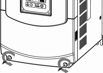
22 3.2.4 Removing the Front Cover and Keypad Before making any wiring connections to the inverter, the front cover needs to be removed. IP00/ IP20 Type Caution It is not required to remove the digital operator before making any wiring connections. Models 200V, 5 30 HP and 400V, 5 40 HP have a plastic cover. Loosen the screws and remove the cover to gain access to the terminals and make wiring connections. Place the plastic cover back and fasten screws when wiring connections have been made. Models 200V, HP and 400V, HP have a metal cover. Loosen the screws and remove the cover to gain access to the terminals and make wiring connections. Place the metal cover back and fasten screws when wiring connections have been made. IP55 Type Caution It is essential to remove the digital operator before making any wiring connections. Model 400V, 5 25 HP has a plastic cover. Loosen the screws and remove the cover to gain access to the terminals and make wiring connections. Place the plastic cover back and fasten screws when wiring connections have been made. Models 400V, HP has a metal cover. Loosen the screws and remove the cover to gain access to the terminals and make wiring connections. Place the metal cover back and fasten screws when wiring connections have been made. 3-8


23 Standard Type (IP00/ IP20) (a) 200V 5-7.5HP/ 400V 5-10HP Step 1: Unscrew Step 2: Remove cover Step 3: Make wire connections and place cover back Step 4: Fasten screw 3-9


24 (b) 200V 10-30HP/ 400V 15-40HP Step 1: Unscrew Step 2: Remove cover Step 3: Make wire connections and place cover back Step 4: Fasten screw 3-10


25 (c) 200V 40-50HP/ 400V 50-75HP Step 1: Unscrew cover Step 2: Remove cover Step 3: Make wire connections and place cover back Step 4: Fasten screw 3-11


26 (d) 200V HP/ 400V HP Step 1: Unscrew cover Step 2: Remove cover Step 3: Make wire connections and place cover back Step 4: Fasten screw 3-12


27 (e) 200V HP/ 400V HP Step 1: Unscrew cover Step 2: Remove cover Step 3: Make wire connections and place cover b Step 4: Fasten screw 3-13


28 (f) 400V HP Step 1: Unscrew cover Step 2: Remove cover Step 3: Make wire connections and place cover back Step 4: Fasten screw 3-14


29 Built-in Filter Type (IP20/ IP00) 400V 5-75HP Step 1: Unscrew cover Step 2: Remove cover Step 3: Unscrew filter section Step 4: Remove filter cover Step 5: Make connections and place filter cover back Step 6: Fasten screw 3-15


")


30 Built-in Filter Type (IP55) (a) 400V 5-25HP Step 1: Unscrew operator Step 2: Remove operator Waterproof gasket Step 3: Pull out operator and remove power line Step 4: Unscrew cover Step 5: Check the inside waterproof gasket is not pulled away from cover while opening the cover 3-16


31 (b) 400V HP Step 1: Unscrew operator Step 2: Remove operator Waterproof gasket Step 3: Pull out operator and remove power line Step4: Unscrew cover and remove it 3-17
32 3.3 Inverter Wiring Wire Gauges and Tightening Torque To comply with UL standards, use UL approved copper wires (rated 75 C) and round crimp terminals (UL Listed products) as shown in table below when connecting to the main circuit terminals. Teco recommends using crimp terminals manufactured by NICHIFU Terminal Industry Co., Ltd and the terminal crimping tool recommended by the manufacturer for crimping terminals and the insulating sleeve. Wire size mm2 (AWG) 0.75 (18) 1.25 (16) 2 (14) 3.5/5.5 (12/10) 8 (8) 14 (6) 22 (4) 30/38 (3 / 2) 50/ 60 (1/ 1/ 0) 70 (2/0) 80 (3/0) 100 (4/0) Table Wire gauges and tightening torque terminal screw size Terminal Screw size Model of round crimp terminal Tightening torque kgf.cm (in.lbs) 3-18 Model of insulating sleeve Model of crimp tool M3.5 R to 10 (7.1 to 8.7) TIC 1.25 NH 1 M4 R to 14 (10.4 to 12.1) TIC 1.25 NH 1 M3.5 R to 10 (7.1 to 8.7) TIC 1.25 NH 1 M4 R to 14 (10.4 to 12.1) TIC 1.25 NH 1 M3.5 R to 10 (7.1 to 8.7) TIC 2 NH 1 / 9 M4 R to 14 (10.4 to 12.1) TIC 2 NH 1 / 9 M5 R to 24 (17.7 to 20.8) TIC 2 NH 1 / 9 M6 R to 30.0 (22.1 to 26.0) TIC 2 NH 1 / 9 M4 R to 14 (10.4 to 12.1) TIC 3.5/5.5 NH 1 / 9 M5 R to 24 (17.7 to 20.8) TIC 3.5/5.5 NH 1 / 9 M6 R to 30.0 (22.1 to 26.0) TIC 3.5/5.5 NH 1 / 9 M8 R to 66.0 (53.0 to 57.2) TIC 3.5/5.5 NH 1 / 9 M4 R to 14 (10.4 to 12.1) TIC 8 NOP 60 M5 R to 24 (17.7 to 20.8) TIC 8 NOP 60 M6 R to 30.0 (22.1 to 26.0) TIC 8 NOP 60 M8 R to 66.0 (53.0 to 57.2) TIC 8 NOP 60 M4 R to 14 (10.4 to 12.1) TIC 14 NH 1 / 9 M5 R to 24 (17.7 to 20.8) TIC 14 NH 1 / 9 M6 R to 30.0 (22.1 to 26.0) TIC 14 NH 1 / 9 M8 R to 66.0 (53.0 to 57.2) TIC 14 NH 1 / 9 M6 R to 30.0 (22.1 to 26.0) TIC 22 NOP 60/ 150H M8 R to 66.0 (53.0 to 57.2) TIC 22 NOP 60/ 150H M6 R to 30.0 (22.1 to 26.0) TIC 38 NOP 60/ 150H M8 R to 66.0 (53.0 to 57.2) TIC 38 NOP 60/ 150H M8 R to 66.0 (53.0 to 57.2) TIC 60 NOP 60/ 150H M10 R to 120 (88.5 to 104) TIC 60 NOP 150H M8 R to 66.0 (53.0 to 57.2) TIC 60 NOP 150H M10 R to 120 (88.5 to 104) TIC 60 NOP 150H M10 R to 120 (88.5 to 104) TIC 80 NOP 150H M16 R to 280 (221 to 243) TIC 80 NOP 150H M10 R to 120 (88.5 to 104) TIC 100 NOP 150H M12 R to 157 (124 to 136) TIC 100 NOP 150H M16 R to 280 (221 to 243) TIC 80 NOP 150H
33 3.3.2 Wiring Peripheral Power Devices Caution After power is shut off to the inverter, the capacitors will slowly discharge. Do NOT touch the inverter circuitry or replace any components until the CHARGE indicator is off. Do NOT wire or connect/disconnect internal connectors of the inverter when the inverter is powered up or when powered off and the CHARGE indicator is on. Do NOT connect inverter output U, V and W to the supply power. This will result in damage to the inverter. The inverter must be by properly grounded. Use terminal E to connect earth ground and comply with local standards. It is required to disconnect the grounded wire in the control board when the inverter is not grounded or floating ground power system. Do NOT perform a dielectric voltage withstand test (megger) on the inverter this will result in inverter damage to the semiconductor components. Do NOT touch any of the components on the inverter control board to prevent damage to the inverter by static electricity. Caution Refer to the recommended wire size table for the appropriate wire to use. The voltage between the power supply and the input of the inverter may not exceed 2%. Phase-to-phase voltage drop (V) = 3 resistance of wire (Ω/km) length of line m) current (km=3280 x feet) / (m=3.28 x feet ) Reduce the carrier frequency (parameter 11-01) If the cable from the inverter to the motor is greater than 25m (82ft). A high-frequency current can be generated by stray capacitance between the cables and result in an overcurrent trip of the inverter, an increase in leakage current, or an inaccurate current readout. To protect peripheral equipment, install fast acting fuses on the input side of the inverter. Refer to section 11.4 for additional information. 3-19
34 Power Supply Molded Circuit Breaker Magnetic Contactor AC Reactor Fast Acting Fuse Input Noise Filter F510 Inverter Ground Output Noise Filter Induction Motor Ground MCCB Power supply: Make sure the correct voltage is applied to avoid damaging the inverter. Molded-case circuit breaker (MCCB) or fused disconnect: A molded-case circuit breaker or fused disconnect must be installed between the AC source and the inverter that conforms to the rated voltage and current of the inverter to control the power and protect the inverter. Do not use the circuit breaker as the run/stop switch for the inverter. Ground fault detector / breaker: Install a ground fault breaker to prevent problems caused by current leakage and to protect personnel. Select current range up to 200mA, and action time up to 0.1 second to prevent high frequency failure. Magnetic contactor: Normal operations do not need a magnetic contactor. When performing functions such as external control and auto restart after power failure, or when using a brake controller, install a magnetic contactor. Do not use the magnetic contactor as the run/stop switch for the inverter. AC line reactor for power quality: When inverters are supplied by a high capacity power source (> 600KVA), an AC reactor can be connected to improve the power factor. Install Fast Acting Fuse: To protect peripheral equipment, install fast acting fuses in accordance with the specifications in section 11.4 for peripheral devices. Input Noise filter: A filter must be installed when there are inductive loads affecting the inverter. The inverter meets EN55011 Class A, category C3 when the TECO special filter is used. See section 11.3 for peripheral devices. Inverter: Output terminals T1, T2, and T3 are connected to U, V, and W terminals of the motor. If the motor runs in reverse while the inverter is set to run forward, swap any two terminals connections for T1, T2, and T3. To avoid damaging the inverter, do not connect the output terminals T1, T2, and T3 to AC input power. Connect the ground terminal properly. (200V series: Rg <100Ω; 400V series: Rg <10Ω.) Output Noise filter: An output noise filter may reduce system interference and induced noise. Motor: If the inverter drives multiple motors the output rated current of the inverter must be greater than the total current of all the motors. 3-20
35 3.3.3 General Wiring Diagram The following is the standard wiring diagram for the F510 inverter ( indicates main circuit terminals and indicates control circuit terminals ). Locations and symbols of the wiring terminal block might be different due to different models of F510. The description of control circuit terminals and main circuit terminals can be referred to Table , and
36 3.3.4 Single/ Multi- Pump Dedicated Wiring Diagram PUMP Wiring Diagram for Pressure Sensor of Voltage Type Single Pump: F510 Single Pump Operation = 1 (Control Circuit Terminal); = 5 (PID) = 0 (0~10V); 10-00=0 (Target Source: Keypad) = 2 (Feedback Source: AI2) = XXX1b( PID is enabled) = 1 (Pump); = 0 (Single Pump) TM2 J P 1 SW3 NPN J P 2 SW2 V I S(+) S(-) S1 S3 S5 24V +10V MT GND GND AI1 AI2 E 24VG S2 S4 S6 F1 F2 PO P I AO1 AO2 E R1A R1B R1C R2A R2C R3A R3C Operation Switch + - Pressure Converter Multi-Pump: S(+) S(-) S1 S3 S5 24V +10V MT GND GND AI1 AI2 E 24VG S2 S4 S6 F1 F2 PO P I AO1 AO2 E S(+) S(-) S1 S3 S5 24V +10V MT GND GND AI1 AI2 E 24VG S2 S4 S6 F1 F2 PO P I AO1 AO2 E R1A R1B R1C R2A R2C R3A R3C R1A R1B R1C R2A R2C R3A R3C 3-22
37 PUMP Wiring Diagram for Pressure Sensor of Current Type Single Pump: Multi-Pump: Notes: 1. The position of dip switch requires being correct (SW2, SW3). 2. It is required to reconnect after setting Master/ Slave. 3-23
38 3. 24VG and GND require short circuit. 4. When the communication modes is selected to be multiple pumps in parallel connection (09-01=3), the baud rate settings (09-02) of Master and Slave are required to be consistent. Refer to parameter for the actions in parallel connection modes. 5. In the wiring of multi-pump current type pressure sensor, it is required to adjust Slave to be 04-07(AI2 Gain) =252.0% and 04-08(AI1 Bias) =25.0%. 3-24
39 3.3.5 Wiring for Control Circuit Terminals Control circuit terminals identification IP20 type 200V: 5HP~50HP,400V: 5HP~75HP S(+) S(-) S1 S3 S5 24V +10V MT GND GND AI1 AI2 E 24VG S2 S4 S6 F1 F2 PO P I AO1 AO2 E R1A R1B R1C R2A R2C R3A R3C 200V: 60HP~125HP,400V: 100HP~800HP S(+) S(-) S1 S3 S5 24V +10V MT GND GND AI1 AI2 E 24VG S2 S4 S6 F1 F2 PO P I AO1 AO2 E R1A R1B R1C R2A R2C R3A R3C IP55 type 400V: 5HP~100HP S(+) S(-) S1 S3 S5 24V +10V MT GND GND AI1 AI2 E 24VG S2 S4 S6 F1 F2 PO P I AO1 AO2 E R1A R1B R1C R2A R2C R3A R3C 3-25
40 Table Description of control circuit terminals Type Terminal Terminal function Signal level/ information S1 2-wire forward rotation/ stop command (default), multifunction input terminals * 1 Digital input signal 24V Power supply Analog input signal S2 S3 S4 S5 2-wire reversal rotation/ stop command (default), multifunction input terminals * 1 Multi-speed/ position setting command 1 (default), multifunction input terminals * 1 Multi-speed/ position setting command 2 (default), multifunction input terminals * 1 Multi-speed/ position setting command 3 (default), multifunction input terminal* 1 S6 Fault reset (default), multi-function input terminal * 1 24V Digital signal SOURCE point (SW3 switched to SOURCE ) 24VG Common terminal of Digital signals Common point of digital signal SINK ( SW3 switched to SINK ) +10V Power for external speed potentiometer MT AI1 AI2 Motor temperature detector of externally connecting PTC Multi-function analog input for speed reference (0-10V input) Multi-function analog input terminals *2, can use SW2 to switch voltage or current input (0~10V)/(4-20mA) GND Analog signal ground terminal ---- E Shielding wire s connecting terminal (Ground) ---- Signal Level 24 VDC (opto-isolated) Maximum current: 8mA Maximum voltage: 30 Vdc Input impedance: 4.22kΩ ±15%, Max. output current: 250mA (The sum of all loads connected) ±5% (Max. current: 20mA ) 1330Ω movement, 550Ω return From 0 to +10V Input impedance: 20KΩ Resolution: 12bit From 0 to +10V Input impedance: 20KΩ From 4 to 20 ma Input impedance: 250Ω Resolution: 12bit Analog output signal AO1 AO2 Multi-function analog output terminals *3 (0~10V/ 4-20mA output) Multi-function analog output terminals *3 (0~10V/ 4-20mA output) From 0 to 10V Max. current: 2mA From 4 to 20 ma Pulse output signal Pulse input signal GND Analog signals ground terminal Max. Frequency: 32KHz PO Pulse output, Band width 32KHz Open Collector output Load: 2.2 KΩ GND Analog signals ground terminal ---- L: from 0.0 to 0.5V PI Pulse command input, frequency width of 32KHz H: from 4.0 to 13.2V Max. Frequency: 0-32KHz Impedance: 3.89 KΩ GND Analog signals ground terminal
41 Table Description of control circuit terminals (Continued) Type Terminal Terminal function Signal level/ information Relay output Safety input R1A- R1B- R1C RS-485 port S (-) Grounding Relay A contact (multi-function output terminal) Relay B contact (multi-function output terminal) Relay contact common terminal, please refer to parameter group 03 in this manual for more functional descriptions. R2A-R2C With the same functions as R1A/R1B/R1C R3A-R3C With the same functions as R1A/R1B/R1C Rating: 250Vac: 10 ma ~ 1A 30Vdc: 10 ma ~ 1A Rating: 250Vac: 10 ma ~ 1A 30Vdc: 10 ma ~ 1A F1 On: normal operation. Off: emergency stop. (Jumper wired has to be removed to use external safety function to stop.) 24Vdc, 8mA, pull-high F2 Safety command common terminal 24V Ground S (+) RS485/MODBUS differential input and output E (G) Grounding to earth Shield the connecting terminal Notes: *1: Multi-function digital input can be referred to in this manual. - Group 03: External Terminals Digital Input / Output Function Group. *2: Multi-function analog input can be referred to in this manual. - Group 04 - External Terminal Analog Signal Input (Output) Function Group. *3: Multi-function analog output can be referred to in this manual. - Group 04 - External Terminal Analog Signal Input (Output) Function Group Caution Maximum output current capacity for terminal 10V is 20mA. Multi-function analog output AO1 and AO2 are for use for an analog output meter. Do not use these output for feedback control. Control board s 24V and 10V are to be used for internal control only. Do not use the internal power-supply to power external devices. 3-27
42 3.3.6 Wiring for Main Circuit Terminals Table Description of main circuit terminals (IP00/IP20 Type) Terminal 200V:5~30HP 400V:5~40HP 200V: 40~175HP 400V: 50~800HP R/L1 S/L2 T/L3 B1/P B2 B1/P- :DC power supply B1/P-B2:external braking resistor - U/T1 V/T2 W/T3 E Input Power Supply Inverter output Ground terminal - :DC power supply or connect braking module - Table Description of main circuit terminals (IP55 Type) Terminal R/L1,S/L2, T/L3 U/T1,V/T2, W/T3 400V 5-100HP Input Power Supply Inverter output B1, B2 Braking resistor connecting terminal *1 1, 2 DC reactor connecting terminal *2 B1, B2, DC power supply (DC+, DC-) Braking module connecting terminal ( PE) Ground terminal *1. The model of 400V 25HP (18.5KW) or below is built-in braking transistor. *2. Before connecting DC reactor, please remove short circuit between terminal 1 and


43 Main circuit terminals identification and screw size IP20 Type 200V: 5-7.5HP/ 400V: 5-10HP T 200V: 10-15HP/ 400V: 15-20HP T Terminal screw size T M4 M4 Terminal screw size T M4 M4 200V: 20-30HP/ 400V: 25-40HP T Terminal screw size T M6 M6 200V: 40-50HP/ 400V: 50-75HP T Terminal screw size T M8 M8 3-29


44 200V: 60-75HP/ 400V: HP T Terminal screw size Power supply T 400V 100HP M8 M10 200V 60-75HP/ 400V 125HP M10 M10 200V: HP/ 400V: HP Terminal screw size T M10 M10 200V: HP/ 400V: HP 400V: HP Terminal screw size T M12 M10 Terminal screw size T M10 M

45 IP55 Type 400V: 5-7.5HP 400V: 10-15HP Terminal screw size T M4 M4 Terminal screw size T M4 M4 400V: 20-25HP Terminal screw size T M6 M6 400V: 30-50HP Terminal screw size T1 M6 M6 3-31


46 400V: 60-75HP Terminal screw size T1 M8 M8 400V : 100HP Terminal screw size T1 T2 M8 M10 M8 3-32
47 Input / Output Power Section Block Diagram The following diagrams show the basic configuration of the power sections for the range of horsepower and input voltages. This is shown for reference only and is not a detailed depiction. IP00/IP20 Type 1. IP20 200V: 5~30HP 400V: 5~40HP 2. IP20 200V: 40~50HP 400V: 50~75HP B1/P B2 R/L1 S/L2 T/L3 U/T1 V/T2 W/T3 R/L1 S/L2 T/L3 U/T1 V/T2 W/T3 SPS CONTROL CIRCUITS SPS CONTROL CIRCUITS E E 3. IP20 200V: 60~75HP 400V: 100~125HP 4. IP20 200V: 100~125HP P P DCL DCL R/L1 S/L2 T/L3 + U/T1 V/T2 W/T3 R/L1 S/L2 T/L3 + U/T1 V/T2 W/T3 N N SPS C/B SPS C/B E SPS E AC/DC 5. IP20 400V: 150~250HP 6. IP20 200V: 150~175HP P P DCL DCL R/L1 S/L2 T/L3 N + U/T1 V/T2 W/T3 R/L1 S/L2 T/L3 N + U/T1 V/T2 W/T3 SPS C/B SPS C/B E AC/DC E AC/DC 3-33
48 7. IP20 400V: 300~425HP 8. IP20 400V: 535~800HP P P DCL R/L1 S/L2 T/L3 N + U/T1 V/T2 W/T3 R/L1 S/L2 T/L3 N U/T1 V/T2 W/T3 SPS C/B SPS C/B E AC/DC E AC/DC IP55 Type 1. IP55 400V: 5~15HP 2. IP55 400V: 20~25HP B1 B2 B1 B2 1 DCL 1 DCL 2 2 R/L1 S/L2 T/L3 Filter U/T1 V/T2 W/T3 R/L1 S/L2 T/L3 Filter U/T1 V/T2 W/T3 SPS C/B SPS C/B E E 3. IP55 400V: 30~100HP 1 DCL 2 R/L1 S/L2 T/L3 Filter U/T1 V/T2 W/T3 SPS C/B E 3-34
49 Cooling Fan Supply Voltage Selection (400V class) The inverter input voltage range of the F V class models ranges from 380 to 460Vac. In these models the cooling fan is directly powered from the power supply. Inverter models F / 4150/ 4175/ 4215/ 4250/ 4300/ 4375/ 4425/ 4535/ 4670/ 4800-H3 requires the user to select the correct jumper position based on the inverter input voltage ("440V" is the default position for these models). Please select the correct position according to the input voltage. If the voltage setting is too low, the cooling fan will not provide adequate cooling for the inverter resulting in an over-heat error. If the input voltage is greater than 460Vac, select the 460V position. (1) 400V: 150HP~250HP TB4(220V) 26CN 440V 33CN FU1 34CN 35CN 220V SA4(220V) 2 1 TB3 + DM1 25CN 220V 32CN 31CN 380V 400/ V 460V 440V S R 4KA69X571W01 4P108C VER.04 36CN JP1 JP2 JP3 JP (2) 400V:300HP~800HP TB4(220V) 26CN 33CN FU1 2 SA4(220V) 1 TB3 + DM1 440V 220V 25CN 36CN 32CN 31CN 34CN 380V 1 35CN 400/ V 220V 440V 460V S R TB2 4KA69X613W JP1 JP2 JP3 JP4 3-35
50 Power Input Wire Size, NFB and MCB Part Numbers The following table shows the recommended wire size, molded case circuit breakers and magnetic contactors for each of the F510 models. It depends on the application whether or not to install a circuit breaker. The NFB must be installed between the input power supply and the inverter input (R/L1, S/L2, T/L3). Note: When using a ground protection, make sure the current setting is above 200mA and trip delay time is 0.1 sec of higher. Power supply 200V 3 Ø 400V 3 Ø NFB *3 Table Wiring Instrument for 200V/400V class (IP00/IP20 type) F510 Model Wire size (mm 2 ) Horse power Rated Rated Main Grounding Control MC *3 (HP) KVA current (A) circuit *1 E(G) line *2 5HP ~ ~ ~2 TO-50EC(30A) CU HP ~2 TO-50EC(30A) CU-16 10HP ~8 0.5~2 TO-100S(50A) CU-18 15HP ~8 0.5~2 TO-100S(50A) CU-25 20HP ~2 TO-100S(100A) CU-50 25HP ~2 TO-100S(100A) CU-65 30HP ~2 TO-225S(100A) CU-80 40HP ~2 TO-225S(150A) CN HP ~2 TO-225S(175A) CN HP ~2 TO-225S(200A) CN HP ~2 TO-225S(225A) CN HP ~2 TO-400S(300A) CN HP ~2 TO-400S(400A) CN HP ~2 TO-600S(600A) S-K HP *2P ~2 TO-800S(800A) S-K600 5HP ~ ~ ~2 TO-50EC(15A) CU HP ~ ~ ~2 TO-50EC(15A) CU-18 10HP ~ ~ ~2 TO-50EC(20A) CU-18 15HP ~2 TO-50EC(30A) CU-25 20HP ~2 TO-100S(50A) CU-25 25HP ~2 TO-100S(50A) CU-35 30HP ~2 TO-100S(50A) CU-50 40HP ~2 TO-100S(75A) CU-50 50HP ~2 TO-100S(100A) CU-65 60HP ~2 TO-100S(100A) CN-80 75HP ~2 TO-225S(150A) CN HP ~2 TO-225S(175A) CN HP ~2 TO-225S(225A) CN HP ~2 TO-400S(300A) CN HP ~2 TO-400S(300A) CN HP ~2 TO-400S(400A) CN HP ~2 TO-400S(400A) S-K HP ~2 TO-600S(600A) S-K HP *2P ~2 TO-800S(800A) S-K HP *2P ~2 TE-1000(1000A) S-K HP *2P ~ HP *2P ~ HP *2P ~
51 *1. The main circuit terminals: R/L1, S/L2, T/L3, U/T1, V/T2, W/T3, B1/P, B2,,. *2. Control line is the terminal wire on the control board. *3. The NFB and MCB listed in the table are of TECO product numbers, products with same rated specification of other brands may be used. To reduce electrical noise interference, ensure that a RC surge absorber (R: 10Ω/ 5W, C: 0.1μf/1000VDC) is added to both sides of MCB coil. Power supply 400V 3 Ø Table Wiring Instrument for 400V class (IP55 type) F510 Model Wire size(mm 2 ) Horse Rated Rated Main Grounding Control NFB *3 MC *3 power current KVA circuit *1 E(G) line *2 (HP) (A) 5HP ~ ~ ~2 TO-50EC(15A) CU HP ~ ~ ~2 TO-50EC(15A) CU-18 10HP ~ ~ ~2 TO-50EC(20A) CU-18 15HP ~2 TO-50EC(30A) CU-25 20HP ~2 TO-100S(50A) CU-25 25HP ~2 TO-100S(50A) CU-35 30HP ~2 TO-100S(50A) CU-50 40HP ~2 TO-100S(75A) CU-50 50HP ~2 TO-100S(100A) CU-65 60HP ~2 TO-100S(100A) CN-80 75HP ~2 TO-225S(150A) CN HP ~2 TO-225S(175A) CN-150 *1. The main circuit terminals: R(L1), S(L2), T(L3),, 1, 2, U(T1), V(T2), W(T3),B1, B2 (Polyethylene power line of 600V is recommended to be used.) *2. Control line is the terminal wire on the control board. *3. The NFB and MCB listed in the table are of TECO product numbers, products with same rated specification of other brands may be used. To reduce electrical noise interference, ensure that a RC surge absorber (R: 10Ω/ 5W, C: 0.1μf/1000VDC) is added to both sides of MCB coil. 3-37
52 3.3.7 Wiring Precautions! Do NOT remove any protective covers or attempt any wiring while input power is applied. Connect all wiring before applying input power. When making wiring changes after power up, remove input power and wait a minimum of five minutes after power has been turned off before starting. Also confirm that the charge lamp is off and that DC voltage between terminals B1/P or (+) and (-) does not exceed 25V, otherwise electric shock may result. Only authorized personnel should work on the equipment. (Take off metal jewelry such as watches and rings and use insulated tools.), otherwise electric shock or injury may result. (A) Wiring for control circuit: (1) Separate the wiring for control circuit terminals from main circuit wiring for terminals (R/L1, S/L2, T/L3, U/T1, V/T2, and W/T3). (2) Separate the wiring for control circuit terminals (R1A, R1B, R1C / R2A, R2C /R3A, R3C) from wiring for terminals S1~S6, A01, A02, GND, +10V-, AI1, AI2, and GND wiring. (3) Use shielded twisted-pair cables (#24 - #14 AWG / mm 2 ) shown in Fig for control circuits to minimize noise problems. The maximum wiring distance should not exceed 50m (165 ft). Figure Shielded Twisted-Pair (B) Wiring for main circuit: (1) The Input power supply voltage can be connected in any phase sequence to power input terminals R/L1, S/L2, or T/L3 on the terminal block. (2) DO NOT connect the AC input power source to the output terminals U/T1, V/T2 and. W/T3. (3) Connect the output terminals U/T1, V/T2, W/T3 to motor lead wires U/T1, V/T2, and W/T3, respectively. (4) Check that the motor rotates forward with the forward run source. If it does not, swap any 2 of the output cables to change motor direction. (5) DO NOT connect phase correcting capacitors or LC/RC noise filter to the output circuit. 3-38
53 (C) Grounding: (1) Connect the ground terminal (E) to ground having a resistance of less than 100Ω. (2) Do not share the ground wire with other devices, such as welding machines or power tools. (3) Always use a ground wire that complies with the local codes and standards for electrical equipment and minimize the length of ground wire. (4) When using more than one inverter, be careful not to loop the ground wire, as shown below in Fig Figure F510 Inverter Grounding 3-39
54 3.3.8 Input Power and Cable Length Cable size The length of the cables between the input power source and /or the motor and inverter can cause a significant phase to phase voltage reduction due to the voltage drop across the cables. The wire size shown in Tables & is based on a maximum voltage drop of 2%. If this value is exceeded, a wire size having larger diameter may be needed. To calculate phase tot phase voltage drop, apply the following formula: Phase-to-phase voltage drop (V) = 3 resistance of wire (Ω/km) length of line m) current (km=3280 x feet) (m=3.28 x feet) Cable length vs. Carrier frequency The allowable setting of the PWM carrier frequency is also determined by motor cable length and is specified in the following Table Table Cable Length vs. Carrier Frequency Cable length between the inverter and Motor in m (ft.). < 30 (100) ( ) ( ) > 100 (329) Recommended carrier frequency allowed Parameter kHz (max) 10 khz (max) 5 khz (max) 2 khz (max) Installing an AC line reactor If the inverter is connected to a large-capacity power source (600kVA or more), install an optional AC reactor on the input side of the inverter. This also improves the power factor on the power supply side. 3-40
55 3.4 Inverter Specifications Basic Specifications (a) 200V class Output Rated Inverter capacity (HP) Rated Output Capacity (KVA) Rated Output Current (A) Maximum Applicable Motor *1 HP (KW) (3.7) (5.5) (7.5) (11) (15) (18.5) (22) (30) (37) (45) (55) (75) (90) (110) (130) Maximum Output Voltage (V) 3-phase 200V~240V Maximum Output Frequency (Hz) Based on parameter setting 0.1~400.0 Hz Power supply Rated Voltage, Frequency 3-phase 200V~240V, 50/60Hz Allowable Voltage Fluctuation -15% ~ +10% Allowable Frequency Fluctuation ±5% (b) 400V class Output Rated Power supply Inverter capacity (HP) Rated Output Capacity (KVA) Rated Output Current (A) Maximum Applicable Motor *1 HP (KW) Maximum Output Voltage (V) Maximum Output Frequency (Hz) 5 (3.7) 7.5 (5.5) 10 (7.5) 15 (11) 3-phase 380V~480V 20 (15) 25 (18.5) 30 (22) 40 (30) Based on parameter setting 0.1~400.0 Hz Rated Voltage, Frequency 3-phase 380V ~ 480V, 50/60Hz Allowable Voltage Fluctuation Allowable Frequency Fluctuation -15% ~ +10% ±5% 50 (37) 60 (45) 75 (55) 100 (75) 125 (90) 150 (110) 175 (132) 215 (160) 250 (185) 300 (220) 375 (280) Output Rated Power supply Inverter capacity (HP) Rated Output Capacity (KVA) Rated Output Current (A) Maximum Applicable Motor *1 HP (KW) Maximum Output Voltage (V) Maximum Output Frequency (Hz) Rated Voltage, Frequency (315) (400) 3-phase 380V~480V Allowable Voltage Fluctuation -15% ~ +10% Allowable Frequency Fluctuation *1: Take standard 4-pole induction motor as the base (500) 800 (600) Based on parameter setting 0.1~400.0 Hz 3-phase 380V ~ 480V, 50/60Hz *2: F510 model is designed to be used in normal duty (ND), whose overload capability is 120% for 1 min. ±5%
56 *3: If it is greater than default carrier frequency, you need to adjust the load current based on the de-rating curve. 200V class Carrier freq. default setting Carrier freq. range 400V class Carrier freq. default setting Carrier freq. range 5~25HP 2KHz 2~16KHz 5~30HP 4KHz 2~16KHz 30HP 2KHz 2~12KHz 40HP 2KHz 2~16KHz 40~50HP 2KHz 2~12KHz (*4) 50~60HP 4KHz 2~12KHz (*4) 60~125HP 2KHz 2~10KHz (*4) 75~215HP 4KHz 2~10KHz (*4) HP 2KHz 2~8KHz 150~175HP 2KHz 2~5KHz 300~375HP 4KHz 2~5KHz HP 2KHz 2~5KHz ~800HP 4KHz 2~5KHz *4: If control mode is set to SLV mode and maximum frequency (01-02) is larger than 80 Hz, the carrier frequency range is 2~8Hz. The following table shows the maximum output frequency for each control mode. Control mode Other settings Maximum output frequency V/F Unlimited 400Hz 200V 5~15HP, 400V 5~20HP 150Hz 200V 20~30HP, 400V 25HP 110Hz 400V 30~40HP 100Hz SLV 200V 40~125HP, 400V 50~215HP, carrier (11-01) is set as 8K or below 8K. 100Hz 200V 40~125HP, 400V 50~215HP, carrier (11-01) is set as above 8K. 80Hz 200V 150~175HP, 400V 250~800HP 100Hz PMSLV Unlimited 400Hz 3-42
57 General Specifications Control Characteristics Protection Function Environment Specifications Operation Modes LED keypad with seven-segment display *5 and LCD keypad (Optional HOA LCD keypad); all LCD keypad with parameter copy function Control Modes V/F, SLV, PMSLV with space vector PWM mode Frequency Control Range 0.1Hz~400.0Hz Frequency Accuracy (Temperature change) Digital references: ±0.01%(-10 to +40 ), Analog references: ±0.1% (25 ±10 ) Speed Control Accuracy ±0.5% (Sensorless Vector Control Mode) *1 Frequency Setting Resolution Digital references: 0.01Hz, Analog references: 0.06Hz/60Hz Output Frequency Resolution 0.01Hz Inverter Overload 120%/1 min Frequency Setting Signal DC 0~+10V / 0~20mA or 4~20mA Acceleration/ Deceleration Time 0.0~ seconds ( separately set acceleration and deceleration time ) Voltage, Frequency Characteristics Custom V/F curve based on parameters Braking Torque About 20% Auto tuning, Soft-PWM, Over voltage protection, Dynamic braking, Speed search, Restart upon momentary power Main Control Functions loss, 2 sets of PID control, Slip Compensation, RS-485 communication standard, Simple PLC function, 2 sets of analog outputs, Safety switch Accumulated power-on/ run time, 4 sets of fault history records and latest fault record state, Energy-saving function Other Functions setting, Phase loss protection, Smart braking, DC braking, Dwell,S curve acceleration and deceleration, Up/Down operation, Modbus, BACnet MS/TP and Metasys N2 communication protocol, Display of multi-engineering unit, Local/ Remote switch, SINK/SOURCE input interface selection, User parameter settings Stall Prevention Current level can be setting (It can be set separately in acceleration or constant speed; it can be set with or without protection in deceleration) Instantaneous Over Current (OC) and Output Short- Inverter stops when the output current exceeds 160% of the inverter rated current Circuit (SC) Protection Inverter Overload Protection (OL2) If inverter rated current 120%/1min is exceeded, inverter stops. The factory default carrier frequency is 2~4KHZ *2 Motor Overload Protection (OL1) Electrical overload protection curve Over voltage (OV) Protection If the main circuit DC voltage rises over 410V (200V class)/ 820V (400V class), the motor stops running. Under voltage (UV) If the main circuit DC voltage falls below 190V (200V class) /380V (400V class), the motor stops running. Protection Auto-Restart after Momentary Power Loss Overheat(OH) Protection Ground Fault (GF) Protection Power loss exceeds 15ms. Auto-restart function available after momentary power loss in 2 sec. Use temperature sensor for protection. Use current sensor for protection. DC Bus Charge Indicator When main circuit DC voltage 50V, the CHARGE LED turns on. Output Phase Loss (OPL) Protection Installation Location Ambient Temperature If the OPL is detected, the motor stops automatically. Indoor (protected from corrosive gases and dust) Storage Temperature -20~+70 (-4 ~+158 ) Humidity -10~+40 (14 ~104 ) (IP20/NEMA1 or IP55/NEMA12), -10~+50 (14 ~122 ) (IP00) without de-rating; with de-rating, its maximum operation temperature is 60 (140 ). 95%RH or less (no condensation) Altitude and Vibration Altitude of 1000m (3181ft) or below, below 5.9m/s 2 (0.6G) Communication Function Built-in RS-485 as standard (Modbus protocol with RJ45/ BACnet/ Metasys N2) PLC Function EMI Protection EMS Protection Safety Certification CE Declaration Built-in UL Certification UL508C The built-in noise filter complies with EN available for inverters 400V 75HP or below (IP20) / 400V 60HP or below (IP55) in compliance with EN in compliance with EN (CE & RE) and EN (LVD, Low-Voltage Directive) Accessories 1 to 8 Pump card, HOA LCD keypad, Profibus card *1: Speed control accuracy will be different from the installation conditions and motor types. *2: The factory default carrier frequency is different from models. 3-43
58 3.5 Inverter Derating Based on Carrier Frequency Note: Derating curve current of carrier frequency means inverter rated current. (a) 200V Models Rated Current Ratio 100% A B 200V 5~20HP Model A 76% 83% 83% B 61% 67% 67% Model A 83% 84% 87% B 66% 67% 70% 0 2KHz 8KHz 16KHz Carrier Frequency (Fc) Rated Current Ratio 100% A B 200V 30~50HP Model A 92% 77% 83% B 74% 62% 67% 0 2KHz 6KHz 12KHz Carrier Frequency (Fc) Rated Current Ratio 100% A 200V 60~175HP Model A 85% 90% 86% B 68% 72% 69% B Model A 91% 87% 92% B 73% 78% 83% 0 2KHz 5KHz 10KHz Carrier Frequency (Fc) 3-44
59 (b) 400V Models Rated Current Ratio 100% A B 400V 5~30HP Model A 100% 83% 85% 78% B 60% 50% 51% 47% Model A 77% 82% 89% B 46% 49% 53% 0 4KHz 8KHz 16KHz Carrier Frequency (Fc) Rated Current Ratio 100% 78% 400V 40HP 47% 0 2KHz 8KHz 16KHz Carrier Frequency (Fc) Rated Current Ratio 100% A B 400V 50~60HP Model A 83% 85% B 67% 68% 0 4KHz 5KHz 12KHz Carrier Frequency (Fc) 3-45
60 Rated Current Ratio 100% A B 400V 75~215HP Model A 88% 81% 91% B 62% 57% 64% Model A 87% 86% 88% B 61% 60% 61% 0 4KHz 5KHz 10KHz Carrier Frequency (Fc) Rated Current Ratio 100% 88% 400V 250HP 78% 0 2KHz 3KHz 5KHz Carrier Frequency (Fc) Rated Current Ratio 100% 400V 300~375HP A Model A 77% 79% 0 4KHz 5KHz Carrier Frequency (Fc) 3-46
61 Rated Current Ratio 100% 87% 400V 425HP 78% 0 2KHz 3KHz 5KHz Carrier Frequency (Fc) Rated Current Ratio 100% 400V 535~800HP 90% 80% 70% 0 2KHz 3KHz 4KHz 5KHz Carrier Frequency (Fc) 3-47
62 3.6 Inverter Derating Based on Temperature Note: User needs to adjust the inverter rated current for ambient temperature to ensure the appropriate industrial application. Rated Current Ratio 100% 60% Temperature 3-48

 (10.98) (6.97) (4.80) (10.51) (0.28) (8.")


63 3.7 Inverter Dimensions Standard Type (IP00/IP20) (a) 200V: 5-7.5HP/ 400V: 5-10HP Inverter Model F H3 F H3 F H3 F H3 F H3 Dimensions in mm (inch) W H D W1 H1 t d NW in kg(lbs) M6 (5.51) (10.98) (6.97) (4.80) (10.51) (0.28) (8.38) M6 (5.51) (10.98) (6.97) (4.80) (10.51) (0.28) (8.38) M6 (5.51) (10.98) (6.97) (4.80) (10.51) (0.28) (8.38) M6 (5.51) (10.98) (6.97) (4.80) (10.51) (0.28) (8.38) M6 (5.51) (10.98) (6.97) (4.80) (10.51) (0.28) (8.38) (b) 200V: 10-30HP/ 400V: 15-40HP 3-48
 W H D W1 H1 t d NW in kg(lbs) 210 300 215 192 286 1.6 6.2 M6 (8.27) (11.81) (8.46) (7.56) (11.")
 (14.17) (8.86) (9.65) (13.39) (0.06) (22.05) 265 360 225 245 340 1.6 10 M8 (10.43) (14.17) (8.86) (9.65) (13.39) (0.06) (22.05) 265 360 225 245 340 1.6 10 M8 (10.43) (14.17) (8.86) (9.65) (13.39) (0.06) (22.05) 210 300 215 192 286 1.")
 (14.17) (8.86) (9.65) (13.39) (0.06) (22.")
 (c) 200V: 40-50HP/ 400V: 50-75HP Inverter Model F510-2040-H3 F510-2050-H3 F510-4050-H3 F510-4060-H3 F510-4075-H3 Dimensions in mm")
 284 525 252 220 505 1.6 30 M8 (11.18) (20.67) (9.92) (8.66) (19.88) (0.06) (66.14) 284 525 252 220 505 1.6 30 M8 (11.18) (20.67) (9.92) (8.66) (19.88) (0.06) (66.14) 284 525 252 220 505 1.6 30 M8 (11.18) (20.67) (9.92) (8.66) (19.88) (0.06) (66.14) 284 525 252 220 505 1.6 30 M8 (11.18) (20.67) (9.92) (8.66) (19.88) (0.06) (66.14) 3-49")

64 Inverter Model F H3 F H3 F H3 F H3 F H3 F H3 F H3 F H3 F H3 F H3 Dimensions in mm (inch) W H D W1 H1 t d NW in kg(lbs) M6 (8.27) (11.81) (8.46) (7.56) (11.26) (0.06) (13.67) M6 (8.27) (11.81) (8.46) (7.56) (11.26) (0.06) (13.67) M8 (10.43) (14.17) (8.86) (9.65) (13.39) (0.06) (22.05) M8 (10.43) (14.17) (8.86) (9.65) (13.39) (0.06) (22.05) M8 (10.43) (14.17) (8.86) (9.65) (13.39) (0.06) (22.05) M6 (8.27) (11.81) (8.46) (7.56) (11.26) (0.06) (13.67) M6 (8.27) (11.81) (8.46) (7.56) (11.26) (0.06) (13.67) M8 (10.43) (14.17) (8.86) (9.65) (13.39) (0.06) (22.05) M8 (10.43) (14.17) (8.86) (9.65) (13.39) (0.06) (22.05) M8 (10.43) (14.17) (8.86) (9.65) (13.39) (0.06) (22.05) (c) 200V: 40-50HP/ 400V: 50-75HP Inverter Model F H3 F H3 F H3 F H3 F H3 Dimensions in mm (inch) W H D W1 H1 t d NW in kg(lbs) M8 (11.18) (20.67) (9.92) (8.66) (19.88) (0.06) (66.14) M8 (11.18) (20.67) (9.92) (8.66) (19.88) (0.06) (66.14) M8 (11.18) (20.67) (9.92) (8.66) (19.88) (0.06) (66.14) M8 (11.18) (20.67) (9.92) (8.66) (19.88) (0.06) (66.14) M8 (11.18) (20.67) (9.92) (8.66) (19.88) (0.06) (66.14) 3-49
65 (d) 200V: HP/ 400V: HP (IP00) Inverter Model F H3 F H3 F H3 F H3 F H3 F H3 F H3 F H3 F H3 F H3 Dimensions in mm (inch) W H D W1 H1 t d NW in kg(lbs) 344 (13.54) 344 (13.54) 459 (18.07) 459 (18.07) 344 (13.54) 344 (13.54) 459 (18.07) 459 (18.07) 459 (18.07) 459 (18.07) 580 (22.83) 580 (22.83) 790 (31.10) 790 (31.10) 580 (22.83) 580 (22.83) 790 (31.10) 790 (31.10) 790 (31.10) 790 (31.10) 300 (11.81) 300 (11.81) (12.78) (12.78) 300 (11.81) 300 (11.81) (12.78) (12.78) (12.78) (12.78) 250 (9.84) 250 (9.84) 320 (12.60) 320 (12.60) 250 (9.84) 250 (9.84) 320 (12.60) 320 (12.60) 320 (12.60) 320 (12.60) 560 (22.05) 560 (22.05) 760 (29.92) 760 (29.92) 560 (22.05) 560 (22.05) 760 (29.92) 760 (29.92) 760 (29.92) 760 (29.92) 1.6 (0.06) 1.6 (0.06) 1.6 (0.06) 1.6 (0.06) 1.6 (0.06) 1.6 (0.06) 1.6 (0.06) 1.6 (0.06) 1.6 (0.06) 1.6 (0.06) M10 M10 M10 M10 M10 M10 M10 M10 M10 M (89.29) 40.5 (89.29) 74 (163.14) 74 (163.14) 40.5 (89.29) 40.5 (89.29) 74 (163.14) 74 (163.14) 74 (163.14) 74 (163.14) 3-50
66 (e) 200V: HP/ 400V: HP (IP20) Inverter Model F H3 F H3 F H3 F H3 F H3 F H3 F H3 F H3 F H3 F H3 Dimensions in mm (inch) W H D W1 H1 t d NW in kg(lbs) (13.72) (13.72) (18.25) (18.25) (13.72) (13.72) (18.25) (18.25) (18.25) (18.25) 740 (29.13) 740 (29.13) 1105 (43.50) 1105 (43.50) 740 (29.13) 740 (29.13) 1105 (43.50) 1105 (43.50) 1105 (43.50) 1105 (43.50) 300 (11.81) 300 (11.81) (12.78) (12.78) 300 (11.81) 300 (11.81) (12.78) (12.78) (12.78) (12.78) 250 (9.84) 250 (9.84) 320 (12.60) 320 (12.60) 250 (9.84) 250 (9.84) 320 (12.60) 320 (12.60) 320 (12.60) 320 (12.60) 560 (22.05) 560 (22.05) 760 (29.92) 760 (29.92) 560 (22.05) 560 (22.05) 760 (29.92) 760 (29.92) 760 (29.92) 760 (29.92) 1.6 (0.06) 1.6 (0.06) 1.6 (0.06) 1.6 (0.06) 1.6 (0.06) 1.6 (0.06) 1.6 (0.06) 1.6 (0.06) 1.6 (0.06) 1.6 (0.06) M10 M10 M10 M10 M10 M10 M10 M10 M10 M10 44 (97.00) 44 (97.00) 81 (178.57) 81 (178.57) 44 (97.00) 44 (97.00) 81 (178.57) 81 (178.57) 81 (178.57) 81 (178.57) 3-51
67 (f) 200V: HP/ 400V: HP (IP00) Inverter Model F H3 F H3 F H3 F H3 F H3 Dimensions in mm (inch) W H D W1 W2 H1 t d NW in kg(lbs) 690 (27.17) 690 (27.17) 690 (27.17) 690 (27.17) 690 (27.17) 1000 (39.37) 1000 (39.37) 1000 (39.37) 1000 (39.37) 1000 (39.37) 410 (16.14) 410 (16.14) 410 (16.14) 410 (16.14) 410 (16.14) 530 (20.87) 530 (20.87) 530 (20.87) 530 (20.87) 530 (20.87) 265 (10.43) 265 (10.43) 265 (10.43) 265 (10.43) 265 (10.43) 960 (37.80) 960 (37.80) 960 (37.80) 960 (37.80) 960 (37.80) 1.6 (0.06) 1.6 (0.06) 1.6 (0.06) 1.6 (0.06) 1.6 (0.06) M12 M12 M12 M12 M (405.65) 184 (405.65) 184 (405.65) 184 (405.65) 184 (405.65) 3-52
68 (g) 200V: HP/ 400V: HP (IP20) Inverter Model F H3 F H3 F H3 F H3 F H3 Dimensions in mm (inch) W H D W1 W2 H1 t d NW in kg(lbs) 690 (27.17) 690 (27.17) 690 (27.17) 690 (27.17) 690 (27.17) (51.69) (16.14) (51.69) (16.14) (51.69) (16.14) (51.69) (16.14) (51.69) (16.14) 530 (20.87) 530 (20.87) 530 (20.87) 530 (20.87) 530 (20.87) (10.43) (37.80) (10.43) (37.80) (10.43) (37.80) (10.43) (37.80) (10.43) (37.80) 1.6 (0.06) 1.6 (0.06) 1.6 (0.06) 1.6 (0.06) 1.6 (0.06) M12 M12 M12 M12 M (427.70) 194 (427.70) 194 (427.70) 194 (427.70) 194 (427.70) 3-53
69 (h) 400V: HP (IP00) Inverter Model F H3 F H3 F H3 Dimensions in mm (inch) W H D W1 W2 W3 H1 H2 H3 t d NW in kg(lbs) 958 (37.72) 958 (37.72) 958 (37.72) 1356 (53.38) 1356 (53.38) 1356 (53.38) 507 (19.96) 507 (19.96) 507 (19.96) 916 (36.06) 916 (36.06) 916 (36.06) 158 (6.22) 158 (6.22) 158 (6.22) 600 (23.62) 600 (23.62) 600 (23.62) 1200 (47.24) 1200 (47.24) 1200 (47.24) 300 (11.81) 300 (11.81) 300 (11.81) 63.5 (2.50) 63.5 (2.50) 63.5 (2.50) 6.2 (0.24) 6.2 (0.24) 6.2 (0.24) M12 M12 M (739) 335 (739) 335 (739) 3-54
70 (i) 400V: HP (IP20) Inverter Model F H3 F H3 F H3 Dimensions in mm (inch) W H D W1 W2 W3 H1 H2 H3 t d NW in kg(lbs) 958 (37.72) 958 (37.72) 958 (37.72) 1756 (69.13) 1756 (69.13) 1756 (69.13) 507 (19.96) 507 (19.96) 507 (19.96) 916 (36.06) 916 (36.06) 916 (36.06) 158 (6.22) 158 (6.22) 158 (6.22) 600 (23.62) 600 (23.62) 600 (23.62) 1200 (47.24) 1200 (47.24) 1200 (47.24) 300 (11.81) 300 (11.81) 300 (11.81) 63.5 (2.50) 63.5 (2.50) 63.5 (2.50) 6.2 (0.24) 6.2 (0.24) 6.2 (0.24) M12 M12 M (772) 350 (772) 350 (772) 3-55
 (a) 400V: 5-10HP Inverter")
 W")
 (15.")
 (12.13) 140 385 28) (12.")
 (b) 400V: 15-40HP 3-56")

71 3.7.2 Models with Built-in Filter (IP00/IP20) (a) 400V: 5-10HP Inverter Model F H3F F H3F F H3F Dimensions in mm (inch) W H D W1 H1 H2 t d NW in kg(lbs) M6 (5.51) (15.16) (6.97) (4.80) (10.51) (10.98) (0.28) (12.13) M6 (5.51) (15.16) (6.97) (4.80) (10.51) (10.98) (0.28) (12.13) M6 (5.51) (15.16) (6.97) (4.80) (10.51) (10.98) (0.28) (12.13) (b) 400V: 15-40HP 3-56
72 Inverter Model F H3F F H3F F H3F F H3F F H3F Dimensions in mm (inch) W H D W1 H1 H2 t d NW in kg(lbs) M6 (8.27) (16.40) (8.46) (7.56) (11.26) (11.81) (0.06) (17.64) M6 (8.27) (16.40) (8.46) (7.56) (11.26) (11.81) (0.06) (17.64) M8 (10.43) (19.69) (8.86) (9.65) (13.39) (14.17) (0.06) (27.56) M8 (10.43) (19.69) (8.86) (9.65) (13.39) (14.17) (0.06) (27.56) M8 (10.43) (19.69) (8.86) (9.65) (13.39) (14.17) (0.06) (27.56) (c) 400V: 50-75HP Inverter Model F H3F F H3F F H3F Dimensions in mm (inch) W H D W1 H1 H2 t d NW in kg(lbs) M8 (11.18) (26.73) (9.92) (8.66) (19.88) (20.67) (0.06) (71.65) M8 (11.18) (26.73) (9.92) (8.66) (19.88) (20.67) (0.06) (71.65) M8 (11.18) (26.73) (9.92) (8.66) (19.88) (20.67) (0.06) (71.65) 3-57
73 3.7.3 Models with Built-in Filter (IP55) (a) 400V: 5-25HP Inverter Model F C3FN4 F C3FN4 F C3FN4 F C3FN4 F C3FN4 F C3FN4 Dimensions in mm (inch) W H D W1 H1 t d NW in kg(lbs) M5 (7.44) (11.18) (7.32) (6.73) (10.47) (0.05) (15.43) M5 (7.44) (11.18) (7.32) (6.73) (10.47) (0.05) (15.43) M5 (9.06) (12.60) (8.27) (8.27) (12.01) (0.08) (23.15) M5 (9.06) (12.60) (8.27) (8.27) (12.01) (0.08) (23.15) M5 (10.43) (15.59) (8.94) (9.80) (14.96) (0.08) (37.48) M5 (10.43) (15.59) (8.94) (9.80) (14.96) (0.08) (37.48) 3-58
74 (b) 400V: 30-60HP (Models of 75~100HP without built-in filter) Inverter Model F C3FN4 F C3FN4 F C3FN4 F C3FN4 F C3N4 F C3N4 Dimensions in mm (inch) W H D W1 H1 t d NW in kg(lbs) M10 (8.82) (20.75) (12.24) (7.09) (19.88) (0.08) (71.65) M10 (8.82) (20.75) (12.24) (7.09) (19.88) (0.08) (71.65) M10 (8.82) (20.75) (12.24) (7.09) (19.88) (0.08) (71.65) M10 (12.83) (27.36) (13.50) (10.87) (26.42) (0.09) (121.25) M10 (12.83) (27.36) (13.50) (10.87) (26.42) (0.09) (121.25) M10 (12.83) (27.36) (13.50) (10.87) (26.42) (0.09) (121.25) 3-59


75 Chapter 4 Keypad and Programming Functions 4.1 LED Keypad Keypad Display and Keys DISPLAY Description 5 Digit LED Display Monitor inverter signals, view / edit parameters, fault / alarm display. LED INDICATORS FAULT LED ON when a fault or alarm is active. FWD LED ON when inverter is running in forward direction, flashing when stopping. REV SEQ REF LED On when inverter is running in reverse direction, flashing when stopping. LED ON when RUN command is from the external control terminals or from serial communication. LED ON when Frequency Reference command is from the external control terminals or from serial communication. 4-1
76 KEYS (8) Description RUN RUN inverter STOP STOP inverter Parameter navigation Up, Increase parameter or reference value LOC/REM DSP/FUN / RESET READ / ENTER Parameter navigation down, decrease parameter or reference value Used to switch between Local Mode and Remote Mode REMOTE Mode: Set by parameters, controlled by control circuit terminals, communication or other ways. LOCAL Mode: Controlled by operator. It displays REMOTE Mode at power-up. Users can switch between LOCAL and REMOTE Mode if they press LOC/ REM keys when the inverter stops. Parameter of can determine if LOC/REM keys are enabled or not. Used to scroll to next screen Frequence screen Function selection Monitor parameter Selects active seven segment digit for editing with the keys Used to reset fault condition. Used to read and save the value of the active parameter. Auto-Repeat Keys Holding the UP or DOWN key for a longer period of time will initiate the auto-repeat function resulting in the value of the selected digit to automatically increase or decrease. 4-2
77 4.1.2 Seven Segment Display Description Actual LED Display Actual LED Display Actual LED Display Actual LED Display 0 A L Y 1 B n 2 C o - 3 D P _ 4 E q. 5 F r 6 G S 7 H t 8 I u 9 J V Display output frequency Frequency Reference Set Frequency Reference LED lights on LED flashes Flashing digit At power-up, the display will show the frequency reference setting and all LEDs are flashing. Press the (UP) or (DOWN) key to enter the frequency reference edit mode, use the /RESET key to select which digit to edit (flashing). Use the (UP) or (DOWN) key to modify the value and press the READ / ENTER key to save the frequency reference and switch back to the frequency reference display mode. During run operation, the display will show the output frequency. Note: When in edit mode and the READ / ENTER is not pressed within 5 sec, the inverter will switch back to the frequency reference display mode. 4-3
78 LED Display Examples Seven Segment Display Description 1. Displays the frequency reference at power-up. 2. Displays the actual output frequency during run operation. Displays parameter code. Displays the setting value of parameter. Displays input voltage. Displays inverter current. Displays DC Bus Voltage. Displays temperature. Displays PID feedback value; The displayed digit is set by Error display; refer to chapter 5 Troubleshooting and Maintenance. Displays AI1/ AI2 input (0~100%) 4-4
79 4.1.3 LED Indicator Description Fault LED State Description FAULT LED Off No Fault Active Illuminated Fault Active Forward LED State Description FWD LED Off Inverter in reverse direction Illuminated Inverter is running in forward direction Flashing Forward direction active, no run command Reverse LED State Description REV LED Off Inverter in forward direction Illuminated Inverter is running in reverse direction Flashing Reverse direction active, no run command RUN LED State Description RUN LED Off Inverter stopped Illuminated Inverter running Flashing Inverter stopped or stopping 4-5
80 SEQ LED State Description SEQ LED Off Sequence controlled from keypad Illuminated Sequence set from external source REF LED State Description REF LED Off Frequency reference set from keypad Illuminated Frequency reference set from external source Run / Stop Status Indicators 0 Output Frequency STOP RUN STOP Frequency Setting RUN STOP ON Flashing OFF 4-6
81 4.1.4 Power-up Monitor Power-up Changing Monitor at Power-up Display Selection Highest bit -> <- Lowest bit The setting range for each bit is 0 ~ 7 from the highest bit to the lowest bit. Range 0: No display 4: Temperature 1: Output current 5: PID feedback 2: Output voltage 6: AI1 value 3: DC voltage 7: AI2 value Example: 12-00= DSP/FUN After 3 sec. Display Voltage Class at Power-up Output Current DSP/FUN Parameter Selection DSP/FUN Switch Mode Frequency Reference 4-7
82 Example: 12-00= Modifying Parameters/ Set Frequency Reference Example: Modifying Parameters 4-8
83 Example: Set Frequency Reference Inverter stopped: Inverter is running: Note: When upper or lower limit is reached during editing of the frequency reference, the edit value will automatically rollover from the lower limit to the upper limit or from the upper limit to the lower limit. 4-9
84 4.1.6 Operation Control Stopped Running Stopping Stopped Output Frequency Stop command FWD command REV command RUN command FWD command REV command Power on FWD Indicator FWD FWD FWD FWD FWD FWD FWD FWD REV Indicator REV REV REV REV REV REV REV REV RUN Indicator RUN RUN RUN RUN RUN RUN RUN RUN STOP Indicator STOP STOP STOP STOP STOP STOP STOP STOP 4-10
85 4.2 LCD keypad Keypad Display and Keys Forward Direction Status Indicator Fault Status Indicator Reverse Direction Status Indicator Local/ Remote Indicator External Reference Indicator External Sequence Indicator LCD Display Run Status Indicator 8 button Membrane Keypad Stop Status Indicator DISPLAY Description LCD Display Monitor inverter signals, view / edit parameters, fault / alarm display. LED INDICATORS FAULT LED ON when a fault or alarm is active. FWD LED ON when inverter is running in forward direction, flashing when stopping. REV SEQ REF LED On when inverter is running in reverse direction, flashing when stopping. LED ON when RUN command is from the external control terminals or from serial communication. LED ON when Frequency Reference command is from the external control terminals or from serial communication. 4-11
86 KEYS (8) Description RUN RUN inverter STOP STOP inverter Parameter navigation Up, Increase parameter or reference value LOC/REM DSP/FUN / RESET READ / ENTER Parameter navigation down, decrease parameter or reference value Used to switch between Local Mode and Remote Mode REMOTE Mode: Set by parameters, controlled by control circuit terminals, communication or other ways. LOCAL Mode: Controlled by operator. It displays REMOTE Mode at power-up. Users can switch between LOCAL and REMOTE Mode if they press LOC/ REM keys when the inverter stops. Parameter of can determine if LOC/REM keys are enabled or not. Used to scroll to next screen Frequence screen Function selection Monitor parameter Selects active seven segment digit for editing with the keys Used to reset fault condition. Used to read and save the value of the active parameter. Auto-Repeat Keys Holding the UP or DOWN key for a longer period of time will initiate the auto-repeat function resulting in the value of the selected digit to automatically increase or decrease. Note: HOA LCD keypad is available with an optional accessory. 4-12
87 4.2.2 Keypad Menu Structure Main Menu The F510 inverter main menu consists of two main groups (modes). The DSP/FUN key is used to switch between the monitor mode and the parameter group mode. Refer to Figure Mode Monitor Mode Parameter Group Mode Description View inverter status, signals and fault data. Access to available parameter groups. All the available parameter groups are listed in the Parameter Group Mode. Use the up and down keys to select a group and press READ/ ENTER to access its parameters. Parameter Group Mode Select parameter group READ ENTER DSP FUN Parameter Mode Select parameter READ ENTER DSP FUN Parameter Edit Mode Change parameter setting RUN DSP FUN Auto-Tune Mode Auto-tune motor Fig Parameter Group Structure Notes: - Always perform auto-tune on the motor before operating the inverter in vector control (sensorless vector or flux vector). Auto-tuning mode will not be displayed when the inverter is running or when a fault is active. - To scroll through the available modes, parameter groups or parameter list press and hold the up or down key. 4-13
88 Monitor Mode In monitor mode inverter signals can be monitored such as output frequency, output current and output voltage, etc ) as well as fault information and fault trace. See Fig for keypad navigation. Parameter Group Selection Mode Monitor Mode Power ON DSP FUN Group 00 Basic Func. 01 V/F Pattern. 02 Motor Parameter DSP FUN Monitor Freq Ref 12-16=005.00Hz 12-17=000.00Hz 12-18=0000.0A DSP FUN Monitor Flt Freq Ref 12-15=000.00Hz 12-17=000.00Hz 12-18=0000.0A DSP FUN Monitor Flt DC Voltage 12-14=0000.0V 12-17=000.00Hz 12-18=0000.0A Fig Monitor Mode 4-14
89 Programming Mode In programming mode inverter parameters can be read or changed. See Fig for keypad navigation. Monitor Mode Power ON Monitor Freq Ref 12-16=005.00Hz 12-17=000.00Hz 12-18=0000.0A DSP FUN Parameter Group Selection Mode Parameter Group Mode Parameter Edit Mode DSP FUN Group 00 Basic Func. 01 V/F Pattern 02 Motor Parameter READ ENTER DSP FUN PARA Control Method -01 Motor Direction -02 Run Source READ ENTER DSP FUN Edit Control Method 0 V/F (0~4) <0> PARA Control Method -01 Motor Direction -02 Run Source READ ENTER DSP FUN Edit Motor Direction 0 Forward (0~1) <0> Press / to edit the setting value or READ/ENTER to save the changes. PARA Control Method -01 Motor Direction -02 Run Source READ ENTER DSP FUN Edit Digital Op (0~4) <1> Run Source DSP FUN Group 00 Basic Fun. 01 V/F Pattern 02 Motor Parameter READ ENTER DSP FUN DSP FUN Group 00 Basic Fun. 01 V/F Pattern 02 Motor Parameter READ ENTER DSP FUN As the above parameter setting Fig Programming Mode Notes: - The parameters values can be changed from the data set/read screen with the (up) or (down) and < / RESET shift key. - To save a parameter press the READ/ENTER key. Return to the previous sub-menu screen press DSP/FUN key. - Press the (up) or (down) key to scroll parameter groups or parameter list. When pressing DSP/FUN in the parameter edit mode, it will return to the previous screen of parameter group mode; when pressing DSP/FUN in the parameter group mode, it will return to the previous screen of parameter group selection mode. - Refer to section 4.4 for parameter details. 4-15
90 Parameter Group Selection Mode Group G English (0~0) <0> Language Parameter Code Parameter Name Setting Value Setting Range Default Value Fig Parameter Group Selection Mode Screen 4-16
91 4.3 Parameters Parameter Group Group 00 Group 01 Group 02 Group 03 Group 04 Group 05 Group 06 Group 07 Group 08 Group 09 Group 10 Group 11 Group 12 Group 13 Group 14 Group 15 Group 16 Group 17 Group 18 Group 19 Group 20 Group 21 Group 22 Group 23 Group 24 Name Basic Parameters V/F Control Parameters IM Motor Parameters External Digital Input and Output Parameters External Analog Input and Output Parameters Multi-Speed Parameters Automatic Program Operation Parameters Start/ Stop Parameters Protection Parameters Communication Parameters PID Parameters Auxiliary Parameters Monitoring Parameters Maintenance Parameters PLC Setting Parameters PLC Monitoring Parameters LCD Parameters IM Motor Automatic Tuning Parameters Slip Compensation Parameters Reserved Speed Control Parameters Torque Control Parameters PM Motor Parameters Pump & HVAC 1 to 8 Pump Card Function Group Parameter Attribute *1 Parameters can be changed during run operation. *2 Read-only parameters for communication. *3 Parameter will not reset to default during a factory reset *4 Read-only parameter *5 Only displayed in using LED keypad *6 Refer to the supplementation 1 if software V1.3 is used. *7 New added parameters in software V1.4 *8 Refer to the supplementation 2 if software V1.5 is used. *9 New added parameters in software V
92 Supplementation 1 Setting range and default value in software V1.3 Code Paramter Name Setting Range Default Value Maximum Output Frequency 10.0~400.0 the same as that in V Poles 2~8 (even) the same as that in V Multi-function Terminal Function Setting-S3 Multi-function Terminal Function Setting-S4 Multi-function Terminal Function Setting-S5 the same as that in V1.4 8 the same as that in V1.4 9 the same as that in V Relay (R1A-R1C) Output 0~ Relay (R2A-R2C) Output 0~ Relay (R3A-R32C) Output 0~ Pre-excitation Level 100~200 the same as that in V Baud-Rate Setting (bps) the same as that in V PID Unit 0~21 the same as that in V Sub-screen Monitoring 1 5~76 the same as that in V Sub-screen Monitoring 2 5~76 the same as that in V Sub-screen Monitoring 3 5~76 the same as that in V Selection of Engineering Unit 0~21 the same as that in V Pole Number of Motor 2~8 (even) the same as that in V Function Selection 0~2 the same as that in V Operation Pressure Setting 0.01 ~ the same as that in V Maximum Pressure Setting 0.01 ~ the same as that in V Tolerance Range of Contant Pressure 0.10 ~ the same as that in V Maximum Pressure Limit 0.10 ~ the same as that in V Minimum Pressure Limit 0.10 ~ the same as that in V Range of Water Pressure Detection 0.10 ~ 2.50 the same as that in V1.4 Parameter in inverter software V1.3 has been transferred to parameter in V
93 Supplementation 2 Setting range and default value in software V1.5 Code Paramter Name Setting Range Default Value Main Frequency Command Source Selection Alternative Frequency Command Source Selection Operation Pressure Setting Tolerance Range of Constant Pressure Maxium Pressure Limit Minimum Pressure Limit Range of Water Pressure Detection Pressure Change Range of Leak Detection Restart Tolerance Range of Leak Detection Restart 0: Keypad 1: External Terminal (Analog) 2: Terminal Command UP/ DOWN 3: Communication Control (RS-485) 4: Reserved 5: PID Given 6: RTC 7: Auxiliary Frequency AI2 0: Keypad 1: External Terminal (Analog) 2: Terminal Command UP/ DOWN 3: Communication Control (RS-485) 4: Reserved 5: PID Given 6: RTC 7: Auxiliary Frequency AI ~ (23-20=0) 0~100%(23-20=1) 0.01 ~ (23-20=0) 0~100%(23-20=1) 0.01 ~ (23-20=0) 0~100%(23-20=1) 0.01 ~ (23-20=0) 0~100%(23-20=1) 0.01 ~ (23-20=0) 0~100%(23-20=1) 0.01 ~ (23-20=0) 0~100%(23-20=1) 0.01~ (23-20=0) 0~100%(23-20=1) the same as that in V1.4 the same as that in V1.4 the same as that in V1.4 (23-20=0) 20% (23-20=1) the same as that in V1.4 (23-20=0) 5% (23-20=1) the same as that in V1.4 (23-20=0) 50% (23-20=1) the same as that in V1.4 (23-20=0) 5% (23-20=1) the same as that in V1.4 (23-20=0) 1% (23-20=1) the same as that in V1.4 (23-20=0) 1% (23-20=1) the same as that in V1.4 (23-20=0) 5% (23-20=1) 4-19
94 Group 00 Basic Parameters Control Mode Code Parameter Name Setting Range Default Unit PM Attribute V/F SLV SLV 0: V/F 1: Reserved Control Mode Selection 2: SLV 0 - O O O *3 3~4: Reserved 5: PM SLV Motor s Rotation Direction 0: Forward 1: Reverse 0 - O O O *1 0: Keypad 1: External Terminal (Control Circuit) Main Run Command Source : Communication Control Selection (RS-485) 0 *note1 - O O O 3: PLC 4: RTC 0: Keypad 1: External Terminal (Control Circuit) Alternative Run Command : Communication Control Source Selection (RS-485) 2 - O O O 3: PLC 4: RTC 0: English Language Selection 1: Simple Chinese 0 - O O O 2: Tranditional Chinese 0: Keypad 1: External Terminal (Analog AI1) 2: Terminal Command UP/ DOWN 3: Communication Control Main Frequency Command (RS-485) Source Selection 4: Reserved 5: PID given 6: RTC 0 *note1 - O O O 7. AI2 Auxiliary Frequency *7 0: Keypad 1: External Terminal (Analog) 2: Terminal Command UP/ DOWN 3: Communication Control Alternative Frequency (RS-485) Command Source Selection 4: Reserved 5: PID 6: RTC 3 - O O O 7. AI2 Auxiliary Frequency *7 0: Main Frequency Main and Alternative : Main Frequency + Alternative Frequency Command Modes Frequency 0 - O O O Communication Frequency Command Range Hz O O O Communication Frequency 0: Do not save when power is off Command Memory Selection 1: Save when power is off. 0 - O O O ~ Reserved Upper Limit Frequency 0.1~ % O O O 4-20
95 Group 00 Basic Parameters Control Mode Code Parameter Name Setting Range Default Unit PM Attribute V/F SLV SLV Lower Limit Frequency 0.0~ % O O O Acceleration Time 1 0.1~ s O O O * Deceleration Time 1 0.1~ s O O O * Acceleration Time 2 0.1~ s O O O * Deceleration Time 2 0.1~ s O O O * Jog Frequency 0.00~ Hz O O O * Jog Acceleration Time 0.1~ s O O O * Jog Deceleration Time 0.1~ s O O O * Acceleration Time 3 0.1~ s O O O * Deceleration Time 3 0.1~ s O O O * Acceleration Time 4 0.1~ s O O O * Deceleration Time 4 0.1~ s O O O *1 Switch-Over Frequency of Acc/Dec Time 1 and Time 4 0.0~ Hz O O O Emergency Stop Time 0.1~ s O O O Reserved 0: Positive Characteristic (0~10V/4~20mA is ~ Main Frequency Command Characteristic Selection corresponding to 0~100%) 1: Negative Characteristic (0~10V/4~20mA is corresponding to 100~0%) 0: Default Value 1: Water Supply Pump Reserved O O O 2: Conveyor * Application Selection Presets 3: Exhaust fan 4: HVAC 0 - O O O 5: Compressor *7 6: Hoist *7 7: Crane * Modified Parameters 0: Enable 1: Disable 0 - O O O ~ Reserved User Parameter 0 Set = 1, and enable user - O O O User Parameter 1 parameter. - O O O User Parameter 2 Setting Range: ~ O O O User Parameter 3 (only used in LCD keypad) - O O O User Parameter 4 - O O O User Parameter 5 - O O O User Parameter 6 - O O O User Parameter 7 - O O O User Parameter 8 - O O O User Parameter 9 - O O O User Parameter 10 - O O O User Parameter 11 - O O O User Parameter 12 - O O O User Parameter 13 - O O O
96 Group 00 Basic Parameters Control Mode Code Parameter Name Setting Range Default Unit PM Attribute V/F SLV SLV User Parameter 14 - O O O User Parameter 15 - O O O *note1: Default value is 1 in software V1.1 or the previous (external control); Default value is 0 in software V1.2 or the following (keypad). Group 01 V/F Control Parameters Control Mode Code Parameter Name Setting Range Default Unit PM Attribute V/F SLV SLV V/F Curve Selection 0~FF 6 - O X X * Reserved Maximum Output Frequency 20.0~ Hz O O O *6 200V: 0.1~ Maximum Output Voltage V O X X 400V: 0.2~ Middle Output Frequency 2 0.0~ Hz O X X 200V: 0.0~ Middle Output Voltage V O X 400V: 0.0~510.0 X Middle Output Frequency 1 0.0~ Hz O X X Middle Output Voltage 1 200V: 0.0~ V: 0.0~ V O X X Minimum Output Frequency 0.0~ Hz O O O Minimum Output Voltage 200V: 0.0~ V: 0.0~ V O X X Torque Compensation Gain 0.0~ O X X * Reserved Base Frequency 10.0~ Hz O O O Base Output Voltage 200V: 0.0~ V: 0.0~ V O X X Input Voltage Setting 200V: 155.0~ V: 310.0~ V O O O Torque Compensation Time 0~ ms O X X Group 02 IM Motor Parameters Control Mode Code Parameter Name Setting Range Default Unit PM Attribute V/F SLV SLV No-Load Current 0.01~ KVA A O X X Rated Current V/F mode is 10%~200% of inverter s rated current; SLV mode is 25%~200% of KVA A O O X inverter s rated current Reserved Rated Rotation Speed 0~60000 KVA Rpm O O X Rated Voltage 200V: 50.0~ V: 100.0~ V O O X Rated Power 0.01~ KVA kw O O X Rated Frequency 10.0~ Hz O O X Poles 2~16 (Even) 4 - O O X * Reserved Excitation Current 15.0~70.0 KVA % X O X 4-22
97 Group 02 IM Motor Parameters Code Parameter Name Setting Range Default Unit Control Mode V/F SLV Core Saturation Coefficient 1 0~100 KVA % X O X Core Saturation Coefficient 2 0~100 KVA % X O X Core Saturation Coefficient 3 80~300 KVA % X O X Core Loss 0.0~15.0 KVA % O X X Reserved Resistance between Wires 0.001~ KVA Ω O O X Rotor Resistance 0.001~ KVA Ω X O X Leakage Inductance 0.01~ KVA mh X O X Mutual Inductance 0.1~ KVA mh X O X No-Load Voltage 200V: 50~ V: 100~480 KVA V X O X ~ Reserved Leakage Inductance Ratio 0.1~15.0 KVA % X O X Slip Frequency 0.10~20.00 KVA Hz X O X PM Attribute SLV Group 03 External Digital Input and Output Parameters Control Mode Code Parameter Name Setting Range Default Unit Multi-function Terminal Function Setting-S1 Multi-function Terminal Function Setting-S2 Multi-function Terminal Function Setting-S V/F SLV 0: 2-Wire Sequence (ON: Forward Run Command) 1: 2-Wire Sequence 0 O O O (ON: Reverse Run Command) 2: Multi-Speed Setting Command 1 O O O 3: Multi-Speed Setting Command 2 1 O O O 4: Multi-Speed Setting Command 3 O O O 5: Multi-Speed Setting Command 4 O O O 2 6: Forward Jog Run Command - O O O 7: Reverse Jog Run Command O O O 8: UP Frequency Increasing 3 Command O O O 9: DOWN Frequency Decreasing Command O O O 10: Acceleration/ Deceleration Setting Command 1 4 O O O 11: Inhibit Acceleration/ Deceleration Command O O O 12: Main/Alternative Run command Switching 17 13: Main/Alternative Frequency Command Switching 14: Emergency Stop (Decelerate to Zero and Stop) - O O O 15: External Baseblock Command (Rotation freely to Stop) 16: PID Control Disable 17: Fault Reset (RESET) PM Attribute SLV *6 *6 *6
98 Group 03 External Digital Input and Output Parameters Control Mode Code Parameter Name Setting Range Default Unit Multi-function Terminal Function Setting-S4 V/F SLV 18: Reserved : Speed Search 1(from the maximum frequency) - O O X 20: Manual Energy Saving Function - O X X 21: PID Integral Reset - O O O 22~23: Reserved : PLC Input 25: External Fault 26: 3-Wire Sequence (Forward/ Reverse Command) 27: Local/ Remote Selection - O O O 28: Remote Mode Selection 29: Jog Frequency Selection 30: Acceleration/ Deceleration Setting Command 2 31: Inverter Overheating Warning 32: Reserved : DC Braking - O X X 34: Speed Search 2 (from Frequency Command) - O X O 35: Timing Function Input 36: PID Soft Start Disable 17 - O O O 37~40: Reserved PM Attribute SLV ~ Multi-function Terminal Function Setting-S5 Multi-function Terminal Function Setting-S (S1~S6) DI Scan Time Multi-Function Terminal (S1-S4 Selection) 41: PID Sleep - O O O 42~46: Reserved : Fire Mode (Forced to Run Mode) - O O O 48: KEB Acceleration - O X X 49: Parameters Writing Allowable - O O O 50: Unattended Start Protection (USP) - O O O 51~52: Reserved : 2-Wire Self Holding Mode (Stop Command) 54: Switch PID1 and PID2 55: RTC Time Enable 56: RTC Offset Enable 57: Forced Frequency Run 58: Run Permissive Function 0: Scan Time 4ms 1: Scan Time 8ms xxx0b:s1 A Contact xxx1b:s1 B Contact xx0xb:s2 A Contact xx1xb:s2 B Contact x0xxb:s3 A Contact x1xxb:s3 B Contact 0xxxb:S4 A Contact 1xxxb:S4 B Contact Reserved O O O 1 - O O O 0000b - O O O
99 Group 03 External Digital Input and Output Parameters Control Mode Code Parameter Name Setting Range Default Unit Multi-Function Terminal (S5-S6 Selection) Relay (R1A-R1C) Output Relay (R2A-R2C) Output 4-25 V/F SLV PM Attribute SLV xxx0b:s5 A Contact xxx1b:s5 B Contact xx0xb:s6 A Contact xx1xb:s6 B Contact x0xxb: Reserved x1xxb: Reserved 0000b - O O O 0xxxb: Reserved 1xxxb: Reserved 0: During Running 1: Fault Contact Output 0 - O O O *6 2: Frequency Agree 3: Setting Frequency Agree (03-13 ± 03-14) O O O 4: Frequency Detection 1 (> 03-13, Hysteresis interval O O O 03-14) 5: Frequency Detection 2 (< 03-13, Hysteresis interval O O O 03-14) 6: Automatic Restart O O O 7~8: Reserved : Baseblock O O O 10~11: Reserved : Over-Torque Detection 13: Current Agree *7 O O O 14~17: Reserved : PLC Status 19: PLC Control 20: Zero Speed 1 - *6 21: Inverter Ready 22: Undervoltage Detection 23: Source of Operation Command O O O 24: Source of Frequency Command 25: Low Torque Detection 26: Frequency Reference Missing 27: Timing Function Output 28~31: Reserved : Communication Control Contacts 33: RTC Timer 1 34: RTC Timer 2 35: RTC Timer 3 O O O 36: RTC Timer 4 37: Detection Output of PID Feedback Loss *7 38: Brake Release *7 X O X Frequency Detection Level 0.0~ Hz O O O Frequency Detection Width 0.1~ Hz O O O Current Agree Level 0.1~ A O O O *7 Delay Time of Current Agree Detection 0.1~ s X O X * ~ Reserved 03-18
100 Group 03 External Digital Input and Output Parameters Control Mode Code Parameter Name Setting Range Default Unit Relay(R1A-R3C)Type ~ UP/DOWN Frequency Hold/ Adjust Selection xxx0b: R1 A Contact xxx1b: R1 B Contact xx0xb: R2 A Contact xx1xb: R2 B Contact x0xxb: R3 A Contact x1xxb: R3 B Contact Reserved 0: Keep UP/DOWN frequency when stopping. 1: Clear UP/DOWN frequency when stopping. 2: Allow frequency UP/DOWN when stopping. 3: Refresh frequency at acceleration. V/F SLV 0000b - O O O 0 - O O O PM Attribute SLV ~ Reserved Pulse Input Selection 0: Common Pulse Input 1: PWM (Pulse Width Modulation) 0 - O O O * Pulse Input Scaling 50~ Hz O O O * Pulse input gain 0.0~ % O O O * Pulse input bias ~ % O O O * Pulse input filter time 0.00~ Sec O O O * ~ Reserved Timer ON Delay (DI/DO) 0.0~ s O O O Timer OFF Delay (DI/DO) 0.0~ s O O O Relay (R3A-R3C) Output Setting range and definition are the same as those of and O O O Up/down Frequency Width Setting 0.00~ Hz O O O * Torque Detection Level 0~ % X O X * Delay Time of Braking Action 0.00~ s X O X *7 4-26
101 Group 04 External Analog Input and Output Parameters Code Parameter Name Setting Range Default Unit AI Input Signal Type AI1 Signal Scanning and Filtering Time 0: AI2: 0~10V/ 0~20mA 1: AI2: 4~20mA/ 2~10V 4-27 Control Mode V/F SLV PM SLV 1 - O O O 0.00~ s O O O Attribute AI1 Gain 0.0~ % O O O * AI1 Bias ~ % O O O * Reserved AI2 Function Setting AI2 Signal Scanning and Filtering Time 0: Auxiliary Frequency O O O 1: Frequency Reference Gain O O O 2: Frequency Reference Bias O O O 3: Output Voltage Bias O X O 4: Coefficient of Acceleration and Deceleration Reduction O O O 5: DC Braking Current O O X 6: Over-Torque Detection Level O O O 7: Stall Prevention Level During Running O X X 8: Frequency Lower Limit 0 - O O O 9: Jump Frequency 4 O O O 10: Added to AI1 O O O 11: Positive Torque Limit X O O 12: Negative Torque Limit X O O 13: Regenerative Torque Limit X O O 14: Positive / Negative Torque Limit X O O 15: Reserved : Torque Compensation X O X 17: Reserved ~ s O O O AI2 Gain 0.0~ % O O O * AI2 Bias ~ % O O O * ~ AO1 Function Setting Reserved 0: Output Frequency 0 - O O O 1: Frequency Command O O O 2: Output Voltage O O O 3: DC Voltage O O O 4: Output Current O O O 5: Output Power O O O 6: Motor Speed O O O 7: Output Power Factor O O O 8: AI1 Input O O O 9: AI2 Input O O O 10: Torque Command X O O
102 Group 04 External Analog Input and Output Parameters Code Parameter Name Setting Range Default Unit Control Mode V/F SLV PM SLV 11: q-axis Current X O O 12: d-axis Current X O O 13: Speed deviation X X O 14: Reserved : ASR Output X X O 16: Reserved : q-axis Voltage X O O 18: d-axis Voltage X O O 19~20: Reserved : PID Input O O O 22: PID Output O O O 23: PID Target Value O O O 24: PID Feedback Value O O O 25: Output Frequency of the Soft Starter O O O 26: PG feedback : PG compesation : Communication Control *6 O O O Attribute AO1 Gain 0.0~ % O O O * AO1 Bias ~ % O O O * ~ Reserved AO2 Function Setting Setting range and definition are the same as O O O AO2 Gain 0.0~ % O O O * AO2 Bias ~ % O O O * AO Output Signal Type 0: AO1:0~10V AO2:0~10V 1: AO1:0~10V AO2:4~20mA 2: AO1:4~20mA AO2:0~10V 0 O O O 3: AO1:4~20mA AO2: 4~20mA Filter Time of AO Signal Scan 0.00~ s O O O *1 *7 4-28
103 Group 05 Multi-Speed Function Group Code Parameter Name Setting Range Default Unit Acceleration and Deceleration Selection of Multi-Speed Frequency Setting of Speed-Stage 0 Frequency Setting of Speed- Stage 1 Frequency Setting of Speed- Stage 2 Frequency Setting of Speed- Stage 3 Frequency Setting of Speed- Stage 4 Frequency Setting of Speed- Stage 5 Frequency Setting of Speed- Stage 6 Frequency Setting of Speed- Stage 7 Frequency Setting of Speed- Stage 8 Frequency Setting of Speed- Stage 9 Frequency Setting of Speed- Stage 10 Frequency Setting of Speed- Stage 11 Frequency Setting of Speed- Stage 12 Frequency Setting of Speed- Stage 13 Frequency Setting of Speed- Stage 14 Frequency Setting of Speed- Stage 15 Acceleration Time Setting of Multi Speed 0 Deceleration Time Setting of Multi Speed 0 Acceleration Time Setting of Multi Speed 1 Deceleration Time Setting of Multi Speed 1 Acceleration Time Setting of Multi Speed 2 0: Acceleration and deceleration time are set by ~ : Acceleration and Deceleration Time are set by ~ Control Mode V/F SLV PM SLV 0 - O O O Attribute 0.00~ Hz O O O *1 0.00~ Hz O O O *7 0.00~ Hz O O O *7 0.00~ Hz O O O *7 0.00~ Hz O O O *7 0.00~ Hz O O O *7 0.00~ Hz O O O *7 0.00~ Hz O O O *7 0.00~ Hz O O O *7 0.00~ Hz O O O *7 0.00~ Hz O O O *7 0.00~ Hz O O O *7 0.00~ Hz O O O *7 0.00~ Hz O O O *7 0.00~ Hz O O O *7 0.00~ Hz O O O *7 0.1~ s O O O 0.1~ s O O O 0.1~ s O O O 0.1~ s O O O 0.1~ s O O O
104 Group 05 Multi-Speed Function Group Code Parameter Name Setting Range Default Unit Deceleration Time Setting of Multi Speed 2 Acceleration Time Setting of Multi Speed 3 Deceleration Time Setting of Multi Speed 3 Acceleration Time Setting of Multi Speed 4 Deceleration Time Setting of Multi Speed 4 Acceleration Time Setting of Multi Speed 5 Deceleration Time Setting of Multi Speed 5 Acceleration Time Setting of Multi Speed 6 Deceleration Time Setting of Multi Speed 6 Acceleration Time Setting of Multi Speed 7 Deceleration Time Setting of Multi Speed 7 Acceleration Time Setting of Multi Speed 8 Deceleration Time Setting of Multi Speed 8 Acceleration Time Setting of Multi Speed 9 Deceleration Time Setting of Multi Speed 9 Acceleration Time Setting of Multi Speed 10 Deceleration Time Setting of Multi Speed 10 Acceleration Time Setting of Multi Speed 11 Deceleration Time Setting of Multi Speed 11 Acceleration Time Setting of Multi Speed 12 Deceleration Time Setting of Multi Speed 12 Acceleration Time Setting of Multi Speed 13 Deceleration Time Setting of Multi Speed Control Mode V/F SLV PM SLV 0.1~ s O O O 0.1~ s O O O 0.1~ s O O O 0.1~ s O O O 0.1~ s O O O 0.1~ s O O O 0.1~ s O O O 0.1~ s O O O 0.1~ s O O O 0.1~ s O O O 0.1~ s O O O 0.1~ s O O O 0.1~ s O O O 0.1~ s O O O 0.1~ s O O O 0.1~ s O O O 0.1~ s O O O 0.1~ s O O O 0.1~ s O O O 0.1~ s O O O 0.1~ s O O O 0.1~ s O O O 0.1~ s O O O Acceleration Time Setting of 0.1~ s O O O Attribute
105 Group 05 Multi-Speed Function Group Code Parameter Name Setting Range Default Unit Multi Speed 14 Deceleration Time Setting of Multi Speed 14 Acceleration Time Setting of Multi Speed 15 Deceleration Time Setting of Multi Speed 15 Control Mode V/F SLV PM SLV 0.1~ s O O O 0.1~ s O O O 0.1~ s O O O Attribute Group 06 Automatic Program Operation Parameters Control Mode Code Parameter Name Setting Range Default Unit PM Attribute V/F SLV SLV 0: Disable 1: Execute a single cycle operation mode. Restart speed is based on the previous stopped speed. 2: Execute continuous cycle operation mode. Restart speed is based on the previous stopped speed Automatic Operation Mode Selection Frequency Setting of Operation-Stage 1 Frequency Setting of Operation -Stage 2 Frequency Setting of Operation -Stage 3 Frequency Setting of Operation -Stage 4 3: After the completion of a single cycle, the on-going operation speed is based on the speed of the last stage. Restart speed is based on the previous stopped speed. 4: Execute a single cycle operation mode. Restart speed will be based on the speed of stage 1. 5: Execute continuous cycle operation mode. Restart speed will be based on the speed of stage 1. 6: After the completion of a single cycle, the on-going operation speed is based on the speed of the last stage. Restart speed is based on the previous stopped speed O O X 0.00~ Hz O O O *1 0.00~ Hz O O O *1 0.00~ Hz O O O *1 0.00~ Hz O O O *1
106 Group 06 Automatic Program Operation Parameters Code Parameter Name Setting Range Default Unit Frequency Setting of Operation -Stage 5 Frequency Setting of Operation -Stage 6 Frequency Setting of Operation -Stage 7 Frequency Setting of Operation -Stage 8 Frequency Setting of Operation -Stage 9 Frequency Setting of Operation -Stage 10 Frequency Setting of Operation -Stage 11 Frequency Setting of Operation -Stage 12 Frequency Setting of Operation -Stage 13 Frequency Setting of Operation -Stage 14 Frequency Setting of Operation -Stage 15 Time Setting of Operation -Stage 0 Time Setting of Operation -Stage 1 Time Setting of Operation -Stage 2 Time Setting of Operation -Stage 3 Time Setting of Operation -Stage 4 Time Setting of Operation -Stage 5 Time Setting of Operation -Stage 6 Time Setting of Operation -Stage 7 Time Setting of Operation -Stage 8 Time Setting of Operation -Stage 9 Time Setting of Operation -Stage 10 Time Setting of Operation -Stage 11 Control Mode V/F SLV PM SLV Attribute 0.00~ Hz O O O *1 0.00~ Hz O O O *1 0.00~ Hz O O O *1 0.00~ Hz O O O *1 0.00~ Hz O O O *1 0.00~ Hz O O O *1 0.00~ Hz O O O *1 0.00~ Hz O O O *1 0.00~ Hz O O O *1 0.00~ Hz O O O *1 0.00~ Hz O O O *1 0.0~ s O O X *1 0.0~ s O O X *1 0.0~ s O O X *1 0.0~ s O O X *1 0.0~ s O O X *1 0.0~ s O O X *1 0.0~ s O O X *1 0.0~ s O O X *1 0.0~ s O O X *1 0.0~ s O O X *1 0.0~ s O O X *1 0.0~ s O O X *1 4-32
107 Group 06 Automatic Program Operation Parameters Code Parameter Name Setting Range Default Unit Time Setting of Operation -Stage 12 Time Setting of Operation -Stage 13 Time Setting of Operation -Stage 14 Time Setting of Operation -Stage 15 Direction Selection of Operation -Stage 0 Direction Selection of Operation -Stage 1 Direction Selection of Operation -Stage 2 Direction Selection of Operation -Stage 3 Direction Selection of Operation -Stage 4 Direction Selection of Operation -Stage 5 Direction Selection of Operation -Stage 6 Direction Selection of Operation -Stage 7 Direction Selection of Operation -Stage 8 Direction Selection of Operation -Stage 9 Direction Selection of Operation -Stage 10 Direction Selection of Operation -Stage 11 Direction Selection of Operation -Stage 12 Direction Selection of Operation -Stage 13 Direction Selection of Operation -Stage 14 Direction Selection of Operation -Stage 15 Control Mode V/F SLV PM SLV Attribute 0.0~ s O O X *1 0.0~ s O O X *1 0.0~ s O O X *1 0.0~ s O O X *1 0: Stop 1: Forward 2: Reverse 0 - O O X 0: Stop 1: Forward 2: Reverse 0 - O O X 0: Stop 1: Forward 2: Reverse 0 - O O X 0: Stop 1: Forward 2: Reverse 0 - O O X 0: Stop 1: Forward 2: Reverse 0 - O O X 0: Stop 1: Forward 2: Reverse 0 - O O X 0: Stop 1: Forward 2: Reverse 0 - O O X 0: Stop 1: Forward 2: Reverse 0 - O O X 0: Stop 1: Forward 2: Reverse 0 - O O X 0: Stop 1: Forward 2: Reverse 0 - O O X 0: Stop 1: Forward 2: Reverse 0 - O O X 0: Stop 1: Forward 2: Reverse 0 - O O X 0: Stop 1: Forward 2: Reverse 0 - O O X 0: Stop 1: Forward 2: Reverse 0 - O O X 0: Stop 1: Forward 2: Reverse 0 - O O X 0: Stop 1: Forward 2: Reverse 0 - O O X 4-33
108 Group 07: Start /Stop Parameters Code Parameter Name Setting Range Default Unit Momentary Power Loss/ Fault Restart Selection 0: Disable 1: Enable 4-34 Control Mode V/F SLV PM SLV 0 - O O O Fault Auto-Restart Time 0~ s O O O Number of Fault Auto-Restart Attempts Reserved DC injection braking starting frequency Automatic start delay at power up DC Injection Braking Start Frequency 0~ O O O 0: DC injection braking is enabled at power up when external run command issues. 1: DC injection braking is disabled at power up when external run command issues. 1 - O O O 1.0~ Sec O O O 0.0~ Hz O O X DC Injection Braking Current 0~ % O O X DC Injection Braking Time at Stop Stop Mode Selection ~ Low Voltage Detection Level 0.00~ s O O X 0: Deceleration to Stop 1: Coast to Stop 2: DC Braking Stop 3: Coast to Stop with Timer Reserved 200V: 150~ V: 300~ O O O V O O O Pre-excitation Time 0.00~ s X O X Attribute Pre-excitation Level 50~ % X O X * DC Injection Braking Time at Start Reserved 0.00~ s O O X Minimum Base block Time 0.1~5.0 - Sec O O O Direction-Detection Speed Search Operating Current Speed Search Operating Current Integral Time of Speed Searching 0~ % O O X 0~ % O O X 0.1~ Sec O O X Delay Time of Speed Search 0.0~ Sec O O X Voltage Recovery Time 0.1~ Sec O O X Direction-Detection Speed Search Selection 0: Disable 1: Enable 0 - O O X Low voltage Detection Time 0.00~ Sec O O O SLV Speed Search Function 0: Enable 1: Disable 0 - X O X
109 Group 07: Start /Stop Parameters Code Parameter Name Setting Range Default Unit Start Selection after Fault during SLV Mode Start Selection after External Base Block 0: Speed search start 1: Normal Start 0: Speed search start 1: Normal Start Control Mode V/F SLV PM SLV 0 - X O O 0 - O O X Attribute Group 08 Protection Parameters Code Parameter Name Setting Range Default Unit Stall Prevention Function Stall Prevention Level in Acceleration xxx0b: Stall prevention is enabled in acceleration. xxx1b: Stall prevention is disabled in acceleration. xx0xb: Stall prevention is enabled in deceleration. xx1xb: Stall prevention is disabled in deceleration. x0xxb: Stall prevention is enabled in operation x1xxb: Stall prevention is disabled in operation 0xxxb: Stall prevention in operation decelerates based on deceleration time 1 1xxxb: Stall prevention in operation decelerates based on deceleration time Control Mode PM Attribute V/F SLV SLV 0000b - O O O 30~ % O O O Stall Prevention Level in 200V: 330~ Deceleration 400V: 660~ Stall Prevention Level in Operation Reserved Selection for Motor Overload Protection (OL1) V O O O 30~ % O O O xxx0b: Motor Overload Protection is disabled xxx1b: Motor Overload Protection is enabled xx0xb: Cold Start of Motor Overload xx1xb: Hot Start of Motor Overload x0xxb: Standard Motor x1xxb: Special motor 0xxxb: Reserved 1xxxb: Reserved 0001b - O O O
110 Group 08 Protection Parameters Code Parameter Name Setting Range Default Unit Start-up Mode of Overload Protection Operation (OL1) 0: Stop Output after Overload Protection 1: Continuous Operation after Overload Protection Reserved ~ Automatic Voltage Regulation (AVR) Selection of Input Phase Loss Protection Selection of Output Phase Loss Protection Selection of Over-Torque Detection Selection of Over-Torque Operation Level of Over-Torque Detection Time of Over-Torque Detection Selection of Low-Torque Detection Selection of Low-Torque Operation Level of Low-Torque Detection 0: Enable 1: Disable 0: Disable 1: Enable 0: Disable 1: Enable Reserved 0: Over-Torque Detection is Disabled. 1: Start to Detect when Reaching the Set Frequency. 2: Start to Detect when the Operation is Begun. 0: Deceleration to Stop when Over- Torque is Detected. 1: Display Warning when Over- Torque is Detected. Go on Operation. 2: Coast to Stop when Over Torque is Detected 4-36 Control Mode V/F SLV PM SLV 0 - O O O 0 - O O O 0 - O O O 0 - O O O 0 - O O O 0 - O O O 0~ % O O O 0.0~ Sec O O O 0: Low-Torque Detection is Disabled. 1: Start to Detect when Reaching the Set Frequency. 2: Start to Detect when the Operation is Begun. 0: Deceleration to Stop when Low- Torque is Detected. 1: Display Warning when Low- Torque is Detected. Go on Operation. 2: Coast to Stop when Low-Torque is Detected 0 - O O O 0 - O O O 0~ % O O O Time of Low-Torque Detection 0.0~ Sec O O O Limit of Stall Prevention in Acc 0~ % O O O Attribute
111 Group 08 Protection Parameters Code Parameter Name Setting Range Default Unit over Base Speed Stall Prevention Detection Time in Operation Ground Fault (GF) Selection ~ ~ Operation Selection of External Fault Detection selection of External Fault Selection of Run Permissive Function Fault Selection of Motor Overheat Time Coefficient of PTC Input Filter Fan Control Function 4-37 Control Mode V/F SLV PM SLV 2~ ms O O O 0: Disable 1: Enable 0: Deceleration to Stop 1: Coast to Stop 2: Continuous Operation 0: Immediately Detect when the Power is Supplied. 1: Start to Detect during Operation 0: Deceleration to Stop 1: Coast to Stop 0: Disable 1: Deceleration to Stop 2: Coast to Stop Reserved Reserved 0 - O O O 0 - O O O 0 - O O O 0 - O O O 0 - O O O 0.00 ~ Sec O O O 0: Start at Operation 1: Permanent Start 2: Start at High Temperature* 0 - O O O Delay Time of Fan Off 0~ Sec O O O Delay Time of Motor Overheat Protection 1~ Sec O O O * Models of inverter ratings above 2040 and 4050 in IP20 enclosure do not have this function. Group 09: Communication Parameters Code Parameter Name Setting Range Default Unit INV Communication Station Addreess Communication Mode Selection Baud Rate Setting (bps) Attribute Control Mode PM Attribute V/F SLV SLV 1~ O O O *2 0: MODBUS 1: BACNET 2: METASYS 3: PUMP in Parallel Connection 4: PROFIBUS 0:1200 1:2400 2:4800 3:9600 4: O O O 3 - O O O *2
112 Group 09: Communication Parameters Code Parameter Name Setting Range Default Unit Stop Bit Selection Parity Selection 5: :1 Stop Bit 1: 2 Stop Bit 0: No Parity 1: Even Bit 2: Odd Bit Reserved Communication Error Detection Time Fault Stop Selection Control Mode PM Attribute V/F SLV SLV 0 - O O O *2 0 - O O O *2 0.0~ S O O O 0: Deceleration to Stop Based on Deceleration Time 1 when Communication Fault Occurs. 1: Coast to Stop when Communication Fault Occurs. 2: Deceleration to Stop Based on Deceleration Time 2 when Communication Fault Occurs. 3: Keep Operating when Communication Fault Occurs. 3 - O O O Comm. Fault Tolerance Count 1~ O O O Waiting Time 5~65 5 ms O O O Device Instance Number 1 ~ O O O Group 10: PID Parameters Control Mode Code Parameter Name Setting Range Default Unit PM Attribute V/F SLV SLV 0: Keypad (for PUMP or HVAC mode) 1: AI1 Given PID Target Value Source : AI2 Given 1 - O O O Setting 3: Reserved 4:10-02 Given PID Feedback Value Source Setting 5: Reserved 1:AI1 Given 2:AI2 Given 3: Reserved O O O PID Target Value 0.0~ % O O O PID Control Mode xxx0b: PID Disable 0000b - O O O xxx1b: PID Enable xx0xb: PID Positive Characteristic xx1xb: PID Negative Characteristic x0xxb: PID Error Value of D Control x1xxb: PID Feedback Value of D Control 0xxxb: PID Output
113 Group 10: PID Parameters Control Mode Code Parameter Name Setting Range Default Unit PM Attribute V/F SLV SLV 1xxxb: PID Output + Target Value Feedback Gain 0.01~ O O O * Proportional Gain (P) 0.00~ O O O * Integral Time (I) 0.00~ s O O O * Differential Time (D) 0.00~ s O O O * Reserved PID Bias ~ % O O O * PID Primary Delay Time 0.00~ s O O O * PID Feedback Loss Detection Selection PID Feedback Loss Detection Level PID Feedback Loss Detection Time 0: Disable 1: Warning 2: Fault O O O 0~100 0 % O O O 0.0~ s O O O PID Integral Limit 0.0~ % O O O * ~ Reserved Start Frequency of PID Sleep 0.00~ Hz O O O Delay Time of PID Sleep 0.0~ s O O O Frequency of PID Waking up 0.00~ Hz O O O Delay Time of PID Waking up 0.0~ s O O O ~ Reserved PID Limit 0.00~ % O O O * PID Output Gain 0.0~ O O O PID Reversal Output Selection PID Target Acceleration/ Deceleration Time 0: Do not Allow Reversal Output 1: Allow Reversal Output 0 - O O O 0.0~ s O O O PID Feedback Display Bias ~ O O O PID Feedback Display Gain 0.00~ O O O PID Sleep Selection 0: Disable 1: Enable 2: Set by DI 1 - O O O Upper Limit of PID Target 0.0 ~ % O O O Lower Limit of PID Target 0.0 ~ % O O O PID Switching Function PID Maximum Feedback Value 0: PID1 1: PID2 2: Set by DI 3: Switch to PID2 when RTC Timer Enables 0 O O O 1~ O O O PID Decimal Width 0~4 1 - O O O PID Unit 0: % 0 - O O O *6
114 Group 10: PID Parameters Control Mode Code Parameter Name Setting Range Default Unit PM Attribute V/F SLV SLV 1: FPM 2: CFM 3: PSI 4: GPH 5: GPM 6: IN 7: FT 8: /s 9: /m 10: /h 11: F 12: inw 13: HP 14: m/s 15: MPM 16: CMM 17: W 18: KW 19: m 20: C 21: RPM 22: Bar 23: Pa PID2 Proportional Gain (P) 0.00~ O O O * PID2 Integral Time (I) 0.0~ s O O O * PID2 Differential Time (D) 0.00~ s O O O * PID Output Frequency Setting during disconnection 00.00~ Hz O O O *6 Group 11: Auxiliary Parameters Code Parameter Name Setting Range Default Unit Direction Lock Selection Carrier Frequency Soft PWM Function Selection Automatic carrier lowering selection 0: Allow Forward and Reverse Rotation 1: Only Allow Forward Rotation 2: Only Allow Reverse Rotation 0: Carrier Output Frequency Tuning 1: 1.5KHz 2~16: 2~16KHz 0: Disable 1: Enable 0: Disable 1: Enable Control Mode PM Attribute V/F SLV SLV 1 - O O O Inverter KVA *a - O O X 1 *b - O O O 0 - O X X 4-40
115 Group 11: Auxiliary Parameters Code Parameter Name Setting Range Default Unit S-curve Time Setting at the Start of Acceleration S-curve Time Setting at the End of Acceleration S-curve Time Setting at the Start of Deceleration S-curve Time Setting at the End of Deceleration 4-41 Control Mode PM Attribute V/F SLV SLV 0.00~ s O O O 0.00~ s O O O 0.00~ s O O O 0.00~ s O O O Jump Frequency 1 0.0~ Hz O O O Jump Frequency 2 0.0~ Hz O O O Jump Frequency 3 0.0~ Hz O O O Jump Frequency Width 0.0~ Hz O O O Manual Energy Saving Gain 0~ % O X X Automatic Return Time 0~ Sec O O O * ~ Reserved Manual Energy Saving Frequency 0.00~ Hz O X X 0: Automatic Energy Saving is Automatic Energy Saving Disabled Function 1: Automatic Energy Saving is Enabled 0 - O X X ~ Filter Time of Automatic Energy Saving Voltage Upper Limit of Energy Saving Tuning Adjustment Time of Automatic Energy Saving Detection Level of Automatic Energy Saving Coefficient of Automatic Energy Saving Auto De-rating Selection ~ Variable Carrier Frequency Max. Limit Variable Carrier Frequency Min. Limit Variable Carrier Frequency Proportional Gain Reference Frequency Loss Detection 0~ ms O X X 0~ % O X X 0~ ms O X X *1 0~ % O X X 0.00~ KVA *a - O X X 0: Disable 1: Enable Reserved 0 - O X X 2~16 KVA *a KHz O X X 2~16 KVA *a KHz O X X 00~ O X X Reserved 0: Deceleration to Stop when Reference Frequency Disappears 0 - O O O
116 Group 11: Auxiliary Parameters Code Parameter Name Setting Range Default Unit Reference Frequency Loss Level 1: Operation is Set by when Reference Frequency Disappears Control Mode PM Attribute V/F SLV SLV 0.0~ % O O O Hold Frequency at Start 0.0~ Hz O O O Frequency Hold Time at Start 0.0~ s O O O Hold Frequency at Stop 0.0~ Hz O O O Frequency Hold Time at Stop 0.0~ s O O O EB Deceleration Time 0.0~ s O X X * KEB Detection Level ~ ~ Braking Selection of Zero Speed Initialization of Cumulative Energy STOP Key Selection UP/DOWN Selection 200V: 190~ V: 380~ : Disable 1: Enable Reserved Reserved 0: Do not Clear Cumulative Energy 1: Clear Cumulative Energy 0: Stop Key is Disabled when the Operation Command is not Provided by Keypad. 1: Stop Key is Enabled when the Operation Command is not Provided by Keypad. 0: When UP/DOWN in Keypad is Disabled, it will be Enabled if Press ENTER after Frequency Modification. 1: When UP/DOWN in Keypad is Enabled, it will be Enabled after Frequency Modification Reserved Record Reference Frequency 0: Disable 1: Enable V O X X 0 - O X X 0 - O O O *1 1 - O O O 0 - O O O 0 - O O O * Prevention of Oscillation Gain 0.01~ O X X * Prevention of Oscillation Upper Limit Prevention of Oscillation Time Parameters Prevention of Oscillation Selection 0~ % O X X *7 0~100 0 O X X *7 0: Mode 1 1: Mode 2 1 O X X *7 *a: KVA means the default value of this parameter will be changed by different capacities of inverter. *b: Default value is 1 only for V/F mode. 4-42
117 Group 12: Monitoring Parameters Control Mode Code Parameter Name Setting Range Default Unit V/F SLV PM SLV Display Screen Selection PID Feedback Display Mode PID Feedback Display Unit Setting Attribute 00000~77777 From the leftmost bit, it displays the screen when press DSP key in order. 0: No display 1: Output Current 2: Output Voltage 3: DC Bus Voltage 4: Heatsink Temperature 5: PID Feedback 6: AI1 Value 7: AI2 Value O O O *5 0: Display the Feedback Value by Integer (xxx) 1: Display the Feedback Value by the Value with First Decimal Place (xx.x) 2: Display the Feedback Value by the Value with Second Decimal Place (x.xx) 0: xxxxx (no unit) 1: xxxpb (pressure) 2: xxxfl (flow) 0 O O O *5 0 O O O * Line Speed Display (LED) 0~ RPM O O O *5 0: Display Inverter Output Frequency 1: Line Speed Display at Integer.(xxxxx) Line Speed Display Mode (LED) 2: Line Speed Display at One Decimal Place. (xxxx.x) 3: Line Speed Display at Two Decimal Places. (xxx.xx) 4: Line Speed Display at Three Decimal Places. (xx.xxx) LED display is shown as below no input 0 O O O * Status display of digital input terminal (LED / LCD) correspondences to input and output - - O O O 4-43

118 Group 12: Monitoring Parameters Control Mode Code Parameter Name Setting Range Default Unit V/F SLV PM SLV Attribute ~ Output Current of Current Fault Output Voltage of Current Fault Output Frequency of Current Fault DC Voltage of Current Fault Frequency Command of Current Fault Frequency Command Output Frequency LCD display is shown as below :OPEN 1:CLOSE Input Terminal(S6) Input Terminal(S5) Input Terminal(S4) Input Terminal(S3) Input Terminal(S2) Input Terminal(S1) Output Terminal(R3) Output Terminal(R2) Output Terminal(R1) Reserved Display the output current of current fault Display the output voltage of current fault Display the output frequency of current fault Display the DC voltage of current fault Display the frequency command of current fault If LED enters this parameter, it only allows monitoring frequency command. Display the current output frequency A O O O - V O O O - Hz O O O - V O O O - Hz O O O - Hz O O O - Hz O O O Output Current Display the current output current - A O O O Output Voltage Display the current output voltage - V O O O DC Voltage Display the current DC voltage - V O O O Output Power Display the current output power - kw O O O Motor s Rotation Speed Display motor s current rotation speed in VF/SLV mode Motor s rotation speed = output power x(120/motor s pole number) In PG/SV mode, motor s rotation speed is calculated by feedback frequency. Max limit is rpm O O O Output Power Factor Display the current output power - - O O O
119 Group 12: Monitoring Parameters Control Mode Code Parameter Name Setting Range Default Unit V/F SLV PM SLV Control Mode AI1 Input AI2 Input Torque Command factor Display control mode 0 : VF 2 : SLV 5 : PM SLV Display the current Al1 input (0V corresponds to 0%, 10V corresponds to 100%,) Display the current Al2 input (0V or 4mA corresponds to 0%, 10V or 20mA corresponds to 100%) Display the current torque command (100% corresponds to motor torque ) - - O O O - % O O O - % O O O - % X O O Motor Torque Current (Iq) Display the current q-axis current - % X O O Motor Excitation Current (Id) Display the current d-axis current - % X O O ~ Reserved PID Input PID Output PID Setting PID Feedback Display input error of the PID controller (PID target value - PID feedback) (100% corresponds to the maximum frequency set by or 01-16) Display output of the PID controller (100% corresponds to the maximum frequency set by or 01-16) Display the target value of the PID controller (100% corresponds to the maximum frequency set by or 01-16) Display the feedback value of the PID controller (100% corresponds to the maximum frequency set by or 01-16) Reserved Heatsink Temperature Display the heatsink temperature of IGBT temperature % O O O - % O O O - % O O O - % O O O - O O O Attribute RS-485 Error Code 1: CRC Error 1: Data length Error 1: Data Function Error 1: Parity Error 1: Overrun Error 1: Framing Error 1: Framing Error Reserved O O O *7
120 Group 12: Monitoring Parameters Control Mode Code Parameter Name Setting Range Default Unit V/F SLV PM SLV Attribute Inverter Status 1: Inverter ready 1: During running 1: During zero speed 1: During speed agree 1: During fault detection (minor fault) 1: During fault detection (major fault) 101B - O O O Reserved Reserved Recent Fault Message Display current fault message - - O O O Previous Fault Message Display previous fault message - - O O O Previous Two Fault Messages Previous Three Fault Messages Previous Four Fault Messages DIO Status of Current Fault Inverter Status of Current Fault Display previous two fault messages Display previous three fault messages Display previous four fault messages Display the DI/DO status of current fault Description is similar to Display the inverter status of current fault Description is similar to O O O - - O O O - - O O O - - O O O - - O O O Trip Time 1 of Current Fault Display the operation time of - Hr O O O current fault, is the days, Trip Time 2 of Current Fault while is the ahemeral hours. - day O O O Frequency Command of Previous Fault Output Frequency of Previous Fault Output Current of Previous Fault Output Voltage of Previous Fault DC Voltage of Previous Fault DIO Status of Previous Fault Inverter Status of Previous Fault Display frequency command of previous fault Display output frequency of previous fault Display output current of previous fault Display output voltage of previous fault Display DC voltage of previous fault Display DI/DO status of previous fault Description is similar to Display inverter status of previous fault Description is similar to Hz O O O - Hz O O O - A O O O - V O O O - V O O O - - O O O - - O O O Trip time 1 of last fault Display the operation time of last - Hr O O O Trip time 2 of last fault time s fault, is the days, while is the ahemeral hours. - day O O O Recent warning messages Previous warning message Display the recent warning messages Display the previous warning message - - O O O - - O O O 4-46
121 Group 12: Monitoring Parameters Control Mode Code Parameter Name Setting Range Default Unit PM V/F SLV SLV ~ Reserved Accumulative Energy (kwhr) 0.0 ~ Accumulative Energy (MWHr) 0 ~ Accumulative Electricity Price ($) Accumulative Electricity Price (10000$) Flow Meter Feedback 1 ~ RTC Date ~ kwh r MW Hr O O O O O O 0 ~ 9999 $ O O O 0 ~ $ O O O GP M O O O O O O RTC Time 00:00 ~ 23:59 00:00 O O O Operating Pressure Setting 0.01 ~ PSI O X X Pressure Feedback Value 0.01 ~ PSI O X X Non-Load Voltage 0.0 ~ V X O X Flow Meter Target Setting 1 ~ Reserved GP M Attribute O O O * Pulse Input Percetage 0.0~ % O O O *7 * Models of inverter ratings above 200V 50HP (including 50HP) and 400V 75HP (including 75HP) in IP20 enclosure do not support functions of heatsink temperature display. All models in IP55 enclosure support functions of heatsink temperature display. * Maximum upper limit in motor speed (rpm) of parameter is Group 13 Maintenance Function Group Control Mode Code Parameter Name Setting Range Default Unit PM Attribute V/F SLV SLV Inverter Rating Selection 00H~FFH - - O O O * Software Version O O O * Reserved Cumulative Operation Hours 1 0~23 - hr O O O * Cumulative Operation Hours 2 0~ day O O O *4 Selection of Accumulative 0: Accumulative time in power on Operation Time 1: Accumulative time in operation 0: Parameters out of are Parameters Locked read-only. 1: Only user parameter is enabled. 2: All parameters are writable Parameter Password Function 0~ O O O Restore Factory Setting 0: No Initialization 2: 2 wire Initialization (200/400V, 60Hz) O O O
122 Group 13 Maintenance Function Group Code Parameter Name Setting Range Default Unit Fault History Clearance Function 3: 3 wire Initialization (200/400V, 60Hz) 4: 2 wire Initialization (200/400V, 50Hz) 5: 3 wire Initialization (200/400V, 50Hz) 6: 2 wire Initialization (200/400V, 50Hz) 7: 3 wire Initialization (200/400V, 50Hz) 8: PLC Initialization 9: 2 Wire Initialization (230V/460V, 60Hz) 10: 3 Wire Initialization (230V/460V, 60Hz) Others: Reserved 0: Do not Clear Fault History 1: Clear Fault History Control Mode V/F SLV PM SLV Attribute 0 - O O O * Password Function 2 0 ~ O O O C/B CPLD Ver. 0.00~ O O O * Option Card Id 0~255 0 O O O * Option Card CPLD Ver. 0.00~ O O O *7 Group 14: PLC Setting Parameters Control Mode Code Parameter Name Setting Range Default Unit PM Attribute V/F SLV SLV T1 Set Value 1 0~ O O O T1 Set Value 2(Mode 7) 0~ O O O T2 Set Value 1 0~ O O O T2 Set Value 2(Mode 7) 0~ O O O T3 Set Value 1 0~ O O O T3 Set Value 2(Mode 7) 0~ O O O T4 Set Value 1 0~ O O O T4 Set Value 2(Mode 7) 0~ O O O T5 Set Value 1 0~ O O O T5 Set Value 2(Mode 7) 0~ O O O T6 Set Value 1 0~ O O O T6 Set Value 2(Mode 7) 0~ O O O T7 Set Value 1 0~ O O O T7 Set Value 2(Mode 7) 0~ O O O T8 Set Value 1 0~ O O O T8 Set Value 2(Mode 7) 0~ O O O C1 Set Value 0~ O O O C2 Set Value 0~ O O O 4-48
123 Group 14: PLC Setting Parameters Code Parameter Name Setting Range Default Unit Control Mode V/F SLV C3 Set Value 0~ O O O C4 Set Value 0~ O O O C5 Set Value 0~ O O O C6 Set Value 0~ O O O C7 Set Value 0~ O O O C8 Set Value 0~ O O O AS1 Set Value 1 0~ O O O AS1 Set Value 2 0~ O O O AS1 Set Value 3 0~ O O O AS2 Set Value 1 0~ O O O AS2 Set Value 2 0~ O O O AS2 Set Value 3 0~ O O O AS3 Set Value 1 0~ O O O AS3 Set Value 2 0~ O O O AS3 Set Value 3 0~ O O O AS4 Set Value 1 0~ O O O AS4 Set Value 2 0~ O O O AS4 Set Value 3 0~ O O O MD1 Set Value 1 0~ O O O MD1 Set Value 2 0~ O O O MD1 Set Value 3 0~ O O O MD2 Set Value 1 0~ O O O MD2 Set Value 2 0~ O O O MD2 Set Value 3 0~ O O O MD3 Set Value 1 0~ O O O MD3 Set Value 2 0~ O O O MD3 Set Value 3 0~ O O O MD4 Set Value 1 0~ O O O MD4 Set Value 2 0~ O O O MD4 Set Value 3 0~ O O O PM SLV Attribute 4-49
124 Group 15: PLC Monitoring Parameters Code Parameter Name Setting Range Default Unit Control Mode V/F SLV T1 Current Value 1 0~ O O O T1 Current Value 2(Mode 7) 0~ O O O T2 Current Value 1 0~ O O O T2 Current Value 2(Mode 7) 0~ O O O T3 Current Value 1 0~ O O O T3 Current Value 2(Mode 7) 0~ O O O T4 Current Value 1 0~ O O O T4 Current Value 2(Mode 7) 0~ O O O T5 Current Value 1 0~ O O O T5 Current Value 2(Mode 7) 0~ O O O T6 Current Value 1 0~ O O O T6 Current Value 2(Mode 7) 0~ O O O T7 Current Value 1 0~ O O O T7 Current Value 2(Mode 7) 0~ O O O T8 Current Value 1 0~ O O O T8 Current Value 2(Mode 7) 0~ O O O C1 Current Value 0~ O O O C2 Current Value 0~ O O O C3 Current Value 0~ O O O C4 Current Value 0~ O O O C5 Current Value 0~ O O O C6 Current Value 0~ O O O C7 Current Value 0~ O O O C8 Current Value 0~ O O O AS1 Results 0~ O O O AS2 Results 0~ O O O AS3 Results 0~ O O O AS4 Results 0~ O O O MD1 Results 0~ O O O MD2 Results 0~ O O O MD3 Results 0~ O O O MD4 Results 0~ O O O TD Current Value 0~ O O O PM SLV Attribute 4-50
125 Group 16: LCD Function Parameters Code Parameter Name Setting Range Default Unit Main Screen Monitoring Sub-Screen Monitoring Sub-Screen Monitoring Selection of Display Unit Selection of Engineering Unit 5~79 When using LCD to operate, the monitored item displays in the first line. (default is frequency command) 5~79 (Parameter 12-05~12-79) When using LCD to operate, the monitored item displays in the second line. (default is output frequency) 5~76(Parameter 12-05~12-79) when using LCD to operate, the monitored item displays in the third line. (default is output current) 0~39999: Determine the display way and unit of frequency command 0: Frequency display unit is 0.01Hz 1: Frequency display unit 0.01% 2: Rpm display; motor rotation speed is set by the control modes to select IM (02-07)/ PM (22-03) motor poles to calculate. 40~9999: Users specify the format, Input 0XXXX represents the display of XXXX at 100% ~19999: Users specify the format; Input 1XXXX represents the display of XXX.X at 100% ~29999: Users specify the format, Input 2XXXX represents the display of XX.XX at 100% ~39999: Users specify the format, Input 3XXXX represents the display of X.XXX at 100%. 0: No Unit 1: FPM 2: CFM 3: PSI 4: GPH 5: GPM 6: IN 7: FT 8: /s 9: /m 10: /h 4-51 Control Mode V/F SLV PM SLV 16 - O O O 17 - O O O 18 - O O O 0 - O O O Attribute *1 *6 *1 *6 *1 *6 0 - O O O *6
126 Group 16: LCD Function Parameters Code Parameter Name Setting Range Default Unit 11: F 12: inw 13: HP 14: m/s 15: MPM 16: CMM 17: W 18: KW 19: m 20: C 21: RPM 22: Bar 23: Pa 4-52 Control Mode V/F SLV PM SLV Attribute LCD Backlight 0~7 5 - O O O * Reserved Copy Function Selection 0: Do not copy parameters 1: Read inverter parameters and save to the operator. 2: Write the operator parameters to inverter. 3: Compare parameters of inverter and operator. 0: Do not allow to read inverter parameters and save to the operator Selection of Allowing Reading 1: Allow to read inverter parameters and save to the operator Selection of Operator Removed (LCD) RTC Time Display Setting 0: Keep operating when LCD operator is removed. 1: Display fault to stop when LCD operator is removed 0: Hide 1: Display RTC Date Setting ~ O O O 0 - O O O 0 - O O O *1 0 O O O O O O RTC Time Setting 00:00 ~ 23:59 00:00 O O O RTC Timer Function 0: Disable 1: Enable 2: Set by DI 0 O O O P1 Start Time 00:00 ~ 23:59 08:00 O O O P1 Stop Time 00:00 ~ 23:59 18:00 O O O P1 Start Date 1:Mon, 2:Tue, 3:Wed, 1 O O O P1 Stop Date 4:Thu,:5:Fri,:6:Sat, 7:Sun 5 O O O P2 Start Time 00:00 ~ 23:59 08:00 O O O P2 Stop Time 00:00 ~ 23:59 18:00 O O O
127 Group 16: LCD Function Parameters Code Parameter Name Setting Range Default Unit 4-53 Control Mode V/F SLV P2 Start Date 1:Mon,2:Tue,3:Wed, 1 O O O P2 Stop Date 4:Thu,:5:Fri,:6:Sat, 7:Sun 5 O O O P3 Start Time 00:00 ~ 23:59 08:00 O O O P3 Stop Time 00:00 ~ 23:59 18:00 O O O P3 Start Date 1:Mon,2:Tue,3:Wed, 1 O O O P3 Stop Date 4:Thu,:5:Fri,:6:Sat, 7:Sun 5 O O O P4 Start Time 00:00 ~ 23:59 08:00 O O O P4 Stop Time 00:00 ~ 23:59 18:00 O O O P4 Start Date 1:Mon, 2:Tue, 3:Wed, 1 O O O P4 Stop Date 4:Thu, 5:Fri, 6:Sat, 7:Sun 5 O O O Selection of RTC Offset 0: Disable 1: Enable 2: Set by DI PM SLV 0 O O O RTC Offset Time Setting 00:00 ~ 23:59 00:00 - O O O Source of Timer 1 0: None,1:P1, 1 O O O Source of Timer 2 2:P2,3:P1+P2 2 O O O Source of Timer 3 4:P3,5:P1+P3, 4 O O O Source of Timer 4 6:P2+P3,7:P1+P2+P3, 8:P4,9:P1+P4, 10:P2+P4, 11:P1+P2+P4 12:P3+P4 13:P1+P3+P4, 14:P2+P3+P4 15:P1+P2+P3+P4, 16:Off,17:Off+P1 18:Off+P2, 19:Off+P1+P2 20:Off+P3, 21:Off+P1+P3 22:Off+P2+P3 23:Off+P1+P2+P3 24:Off+P4 25:Off+P1+P4 26:Off+P2+P4 27:Off+P1+P2+P4 28:Off+P3+P4 29:Off+P3+P4 30:Off+P2+P3+P4 31:Off+P1+P2+P3+P4 8 O O O Selection of RTC Speed 0: Off 1: By Timer 1 2: By Timer 2 3: By Timer 3 4: By Timer 4 0 O O O Attribute
128 Group 16: LCD Function Parameters Code Parameter Name Setting Range Default Unit Selection of RTC Rotation Direction 5: By Timer 1+2 xxx0b: RTC Run1 Forward Rotation xxx1b: RTC Run1 Reverse Rotation xx0xb: RTC Run2 Forward Rotation xx1xb: RTC Run2 Reverse Rotation x0xxb: RTC Run3 Forward Rotation x1xxb: RTC Run3 Reverse Rotation 0xxxb: RTC Run4 Forward Rotation 1xxxb: RTC Run4 Reverse Rotation Control Mode V/F SLV PM SLV O O O Attribute Group 17: IM Motor Automatic Tuning Parameters Control Mode Code Parameter Name Setting Range Default Unit PM Attribute V/F SLV SLV 0: Rotation Auto-tune 1: Static Auto-tune Mode Selection of Automatic : Stator Resistance Measurement Tuning 3: Reserved 4: Loop Tuning 2 *c - O O X Motor Rated Output Power 0.00~ KW O O X Motor Rated Current 0.1~ A O O X Motor Rated Voltage 200V: 0.0~ V:0.0~ V O O X Motor Rated Frequency 10.0~ Hz O O X Motor Rated Speed 0~24000 KVA *a rpm O O X Pole Number of Motor 2~16 (Even) 4 Pole O O X * Reserved Motor No-load Voltage Motor Excitation Current Automatic Tuning Start Error History of Automatic Tuning 200V: 50~ V100~ ~ (15%~70% motor rated current) 0: Disable 1: Enable 0: No Error 1: Motor Data Error 2. Stator Resistance Tuning Error 3. Leakage Induction Tuning Error 4. Rotor Resistance Tuning Error KVA *a V O O X KVA *a A O O X 0 - O O X 0 - O O X
129 Group 17: IM Motor Automatic Tuning Parameters Code Parameter Name Setting Range Default Unit 5. Mutual Induction Tuning Error 6. Reserved 7. DT Error 8. Motor Acceleration Error 9. Warning Control Mode V/F SLV Leakage Inductance Ratio 0.1 ~ % X O X Slip Frequency 0.10 ~ Hz X O X PM SLV *c: Default value is 2 in V/F mode while it is 0 in SLV mode. *a: KVA means the default value of this parameter will be changed by different capacities of inverter. Attribute Group 18: Slip Compensation Parameters Code Parameter Name Setting Range Default Unit Slip Compensation Gain at Low Speed Slip Compensation Gain at High Speed Control Mode V/F SLV PM Attribute SLV 0.00~ *d - O O X *1-1.00~ O O X * Slip Compensation Limit 0~ % O X X Slip Compensation Filter Time 0.0~ Sec O X X Regenerative Slip Compensation Selection 0: Disable 1: Enable 0 - O X X FOC Delay Time 1~ ms X O X FOC Gain 0.00~ X O X *d: Default value is 0.00 in V/F mode while it is 1.0 in SLV mode. Group 19 Reserved Group 20 Speed Control Parameters* Code Parameter Name Setting Range Default Unit 4-55 Control Mode V/F SLV PM SLV Attribute ASR Gain ~ X O O * ASR Integral Time ~ SLV: PMSLV :0.08, Sec X O O * ASR Gain ~ X O O * ASR Integral Time ~ SLV: PMSLV :0.08, Sec X O O * ASR Integral Time Limit 0~ % X O O Reserved
130 Group 20 Speed Control Parameters* Code Parameter Name Setting Range Default Unit ~ Selection of Acceleration and Deceleration of P/PI 0: PI speed control will be enabled only in constant speed. For accel/ ecal, only use P control. 1: Speed control is enabled either in constant speed or accel/decal. Control Mode V/F SLV PM SLV 1 - X O X ASR Delay Time 0.000~ Sec X O X Speed Observer Proportional (P) Gain 1 Speed Observer Integral(I) Time Speed Observer Proportional (P) Gain 2 Speed Observer Integral(I) Time Low-pass Filter Time Constant of Speed Feedback 1 Low-pass Filter Time Constant of Speed Feedback 2 Attribute 0.00~ X O X *1 0.01~ Sec X O X *1 0.00~ X O X *1 0.01~ Sec X O X *1 1~ ms X O X 1~ ms X O X ASR Gain Change Frequency 1 0.0~ Hz X O X ASR Gain Change Frequency 2 0.0~ Hz X O X Torque Compensation Gain at Low Speed Torque Compensation Gain at High Speed ~ ~ X O -10~10 0 % X O Reserved Constant Speed Detection Level 0.1~ X O O * Derating of Compensation Gain 0~ X O X * Derating of Compensation Time 0~ ms X O X *7 *: This parameter group is enabled in SLV and PMSLV modes. X X *1 *1 Group 21 Torque Control Parameters Code Parameter Name Setting Range Default Unit ~ Reserved 4-56 Control Mode V/F SLV PM Attribute SLV Positive Torque Limit 0~ % X O O Negative Torque Limit 0~ % X O O Forward Regenerative Torque Limit 0~ % X O O Reversal Regenerative Torque 0~ % X O O
131 Group 21 Torque Control Parameters Code Parameter Name Setting Range Default Unit Limit Control Mode V/F SLV PM SLV Attribute Group 22: PM Motor Parametersonly available when PM Control Mode is selected 4-57 Control Mode Code Parameter Name Setting Range Default Unit V/F SLV PM SLV Rated Power of PM Motor 0.00~ KVA kw X X O Rated Voltage of PM Motor 200V: 50.0~ V: 100.0~ V X X O Rated Current of PM Motor 0.1~999.9 KVA A X X O Pole Number of PM Motor 2~ Rated Rotation Speed of PM Motor Maximum Rotation Speed of PM Motor 1~60000 (22-04, 22-06, only need to set one of them, the program will calculate the other.) pole s X X O 1500 rpm X X O 1~ rpm X X O PM Motor Rated Frequency 0.0~ Hz X X O ~ Reserved PM SLV Start Current DC Injection Current 0 ~ 120% Motor Rated Current 0 ~ 100% Motor Rated Current 50 % X X O 40 % X X O Attribute Speed Estimation kp Value 1~ X X O * Speed Estimation ki Value 1~ X X O * PM Motor Armature Resistance ~ Ω X X O PM Motor D-axis Inductance ~ mh X X O PM Motor Q-axis Inductance ~ mh X X O ~ Reserved SLV PM Motor Tuning Fault History of SLV PM Motor Tuning 0: Disable 1: Enable 0. No Error 1~4: Reserved 5: Circuit tuning time out. 6: Reserved 7: Other motor tuning errors 8: Reserved 9: Current Abnormity Occurs while Loop Adjustment. 10: Reserved 11: Stator Resistance Measurement Timeout 12: Reserved 0 - X X O 0 -- X X O *4
132 Group 23 Pump & HVAC Function Parameters Code Parameter Name Setting Range Default Unit Function Selection Setting of Single & Multiple Pumps and Master & Slave Machines 0: Disable 1: Pump 2: HVAC 3: Compressor *7 0: Single Pump 1: Master 2: Slave 1 3: Slave 2 4: Slave 3 Control Mode V/F SLV PM SLV 0 - O O O 0 O X X Attribute Operation Pressure Setting 0.01 ~ PSI O X X *6 * Maximum Pressure Setting 0.01 ~ PSI O X X *6 Pump Pressure Command 0: Set by Source 1: Set by AI 0 0 O X X Display Mode Selection 0: Display of Target and Preesure Feedback * 1: Only Display Target Pressure 2: Only Display Feedback Pressure 0 % O X X Proportion Gain (P) 0.00~ O X X Integral Time (I) 0.0~ Sec O X X Differential Time (D) 0.00~ Sec O X X Tolerance Range of Constant Pressure Sleep Frequency of Constant Pressure Sleep Time of Constant Pressure 0.10 ~ PSI O X X 0.00 ~ Hz O X X 0.0 ~ Sec O X X Maximum Pressure Limit 0.00 ~ PSI O X X Warning Time of High Pressure 0.0 ~ Sec O X X Stop Time of High Pressure 0.0 ~ Sec O X X Minimum Pressure Limit 0.00 ~ PSI O X X Warning Time of Low Pressure 0.0 ~ Sec O X X Fault Stop Time of Low Pressure 0.0 ~ Sec O X X Detection Time of Loss Pressure 0.0 ~ Sec O X X Detection Proportion of Loss Pressure Percentage of Pressure Level ~ Direction of Water Pressure Detection 0 ~ % O X X 0: Pressure Unit Setting 1: Pressure Percentage Setting 0: Upward Detection Reserved 1: Downward Detection *6 *8 *6 *8 *6 *8 0 O X X *9 1 - O Range of Water Preesure 0.0 ~ PSI O X X *6 X X X X 4-58
133 Group 23 Pump & HVAC Function Parameters Code Parameter Name Setting Range Default Unit Control Mode V/F SLV PM SLV Attribute Detection *8 Period of Water Preesure Detection Acceleration Time of Water Pressure Detection Deceleration Time of Water Pressure Detection 0.0 ~ Sec O X X 0.1 ~ KVA Sec O X X 0.1 ~ KVA Sec O X X Foreced Run Command 0.0 ~ Hz- O X X Switching Time of Multiple Pumps in Parallel 0 ~ Hr O X X Detection Time of Multiple Pumps in Parallel Running Start 0.0 ~ Sec O X X Synchronous Selection of Multiple Pumps in Parallel ~ : Disable 1: Pressure Setting and Run/Stop 2: Pressure Setting 3: Run/Stop Reserved O X X Leakage Detection Time 0.0~ Sec O X X *7 Pressure Variation of Leakage Detection Restart Pressure Tolerance Range of Leakage Detection Restart Reserved Local/ Remote Key Energy Recaculating 0.01~ PSI O X X *7 0.01~ PSI O X X *7 0: Disable 1: Enable 0: Disable (Energy Accumulating) 1: Enable 1 O O O 0 O O O Electricity Price per kwh ~ $ O O O Selection of Accumulative Electricity Pulse Output Unit Given Modes of Flow Meters Feedback 0: Disable 1: Unit for 0.1kWh 2: Unit for 1kWh 3: Unit for 10kWh 4: Unit for 100kWh 5: Unit for 1000kWh 0: Disable 1: Analog Input 2: Pulse Input 0 O O O 1 O O O Maximum Value of Flow Meters 1 ~ GPM O O O Target Value of Flow Meters 1 ~ GPM O O O Maximum Flow Value of Feedback Maximum Flow Warning Time of Feedback 0.01 ~ % O O O 0.0 ~ Sec O O O Maximum Flow Stop Time of 0.0 ~ Sec O O O
134 Group 23 Pump & HVAC Function Parameters Code Parameter Name Setting Range Default Unit Feedback Minimum Flow Value of Feedback Minimum Flow Warning Time of Feedback Minimum Flow Stop Time of Feedback Detection Function of Low Suction Control Mode V/F SLV PM SLV 0.01 ~ % O O O 0.0 ~ Sec O O O 0.0 ~ Sec O O O 0: Disable 1: PID Error Value 2: Current 3: Current and PID Error Value 0 O O O Detection Time of Low Suction 0 ~ Sec O O O PID Error Level of Low Suction 0 ~ % O O O Current Level of Low Suction(Motor Rated Current) Reaction of Low Suction Source of HVAC Pressure Command ~ ~ % O O O 0: Disable 1: Warning 2: Fault 3: Fault & Restart 0: Set by : Set by AI Reserved 0 O O O 0 O O O Derating of Current Level 10~ % O X X Derating of Delay Time 1.0~ Sec O X X Derating of Frequency Gain 1~ % O X X OL4 Current Level 10~ % O X X OL4 Delay Time 0~ Sec O X X *Note: With LED keypad, setting of needs to be lower than 9.9 PSI in the pump modes; is lower than 1000 and 10-34=1 in the PID modes. Attribute 4-60
135 Group 24 Pump Control Function Parameters Control Mode Code Parameter Name Setting Range Default Unit V/F SLV PM SLV Selection of Pump Control Function Selection of Relay 2-4 Function Selection of Relay 5-8 Function Duration of Upper Limit Frequency Duration of Lower Limit Frequency Switching Time of Magnetic Contactor 0: Function of 1 to 8 Pump Card is Disabled 1: Fixed Modes of Inverter Pump: First on and Last off; then Stop All. 2: Fixed Modes of Inverter Pump: Only Stop Inverter Pump. 3: Fixed Modes of Inverter Pump: First on and First Off; then Stop All. 4: Cycle Modes of Inverter Pump: First on and First Off; then Stop All. 5: Cycle Modes of Inverter Pump: Only Stop Inverter Pump. 6: 1 to 3 Relay of Cycle Modes of Inverter Pump: First on and First off; then Stop All xxx0b: Reserved xxx1b: Reserved xx0xb: Realy 2 Disable xx1xb: Realy 2 Enable x0xxb: Realy 3 Disable x1xxb: Realy 3 Enable 0xxxb: Realy 4 Disable 1xxxb: Realy 4 Enable xxx0b: Realy 5 Disable xxx1b: Realy 5 Enable xx0xb: Realy 6 Disable xx1xb: Realy 6 Enable x0xxb: Realy 7 Disable x1xxb: Realy 7 Enable 0xxxb: Realy 8 Disable 1xxxb: Realy 8 Enable 0 - O O O 0000b O O O 0000b O O O Attribute 1.0 ~ Sec O O O *1 1.0 ~ Sec O O O *1 0.1 ~ Sec O O O * Allowable Bias of Pump Switch 0.0 ~ % O O O *1 0: 1 to 8 pump card Pump Control Source Selection 1: Built-in 1 to 3 control mode 0 O O O 4-61
136 4.4 Description of Parameters Group 00-Basic Parameters Control Mode Selection 0 : V/F 1 : Reserved 2 : SLV Range 3 : Reserved 4 : Reserved 5 : PMSLV The inverter offers the following control modes: 00-00=0: V/F Mode Select the required V/F curve (01-00) based on your motor and application. Perform a stationary auto-tune (17-00=2). If the motor cable length is longer than 50m (165ft), see parameter for details =2: Sensorless Vector Control Verify the inverter rating matches the motor rating. Perform rotational auto-tune to measure and store motor parameters for higher performance operation. Perform non-rotational auto-tune if it s not possible to rotate the motor during auto-tune. Refer to parameter group 17 for details on auto-tuning =5: PM Sensorless Vector Control Verify the inverter rating matches the motor rating. Set PM motor data in parameters to Refer to parameter for details on PM Motor tuning. Braking Resistor Choose a braking resistor based on application and drive model used. A braking module is required for Inverters ratings 200V 30HP, 400V/40HP or greater. Note: Parameter is excluded from initialization Motor s Rotation Direction Range 0 : Forward 1 : Reverse Use the FWD/REV key to change motor direction when Run Command Selection (00-02 = 0) is set to keypad control. In keypad control operation the direction is stored in Direction of this function will be limited to the motor direction lock selection of parameter Main Run Command Source Selection 0 :Keypad control 1 :External terminal control Range 2 :Communication control 3 :PLC 4 :RTC 00-02=0: Keypad Control Use the keypad to start and stop the inverter and set direction with the forward / reverse key. Refer to section 4-1 for details on the keypad. 4-62
137 00-02=1: External Terminal Control External terminals are used to start and stop the inverter and select motor direction. The inverter can be operated in 2-wire and 3-wire mode Alternative Run Command Source Selection 0 :Keypad control 1 :External terminal control Range 2 :Communication control 3 :PLC 4 :RTC 00-03=0: Keypad Control Use the keys (Stop/ Run or FWD/ REV) in the keypad via the setting of 00-03=0 to run the inverter (please refer to section 4.1 for details on the keypad) =1: External Terminal Control External terminals are used to start and stop the inverter and select motor direction via the setting of 00-03=1. Note: It is required to switch the command via the setting of multi-function digital input terminals (03-00~03-05) to 12 (Main/Alternative Run command Switching). 2-wire operation For 2-wire operation, set (S1 terminal selection) to 0 and (S2 terminal selection) to 0. Terminal S1 Terminal S2 Operation Open Open Stop Inverter Closed Open Run Forward Open Closed Run Reverse Closed Closed Stop Inverter, Display EF9 Alarm after 500ms Parameter to 2, 4 or 6 for 2-wire program initialization, multi-function input terminal S1 is set to forward, operation/ stop, and S2 is set for reverse, operation / stop. Forward, Run / Stop S1 Reverse Run / Stop S2 24VG Figure Wiring example of 2-wire 4-63
138 3-wire operation For 3-wire operation set any of parameters to (terminal S3 ~ S6) to 26 to enable 3-wire operation in combination with S1 and S2 terminals set to operation command and stop command. Parameter to 3, 5 or 7 for 3-wire program initialization, multi-function input terminal S1 is set to run operation, S2 for stop operation and S5 for forward/reverse command. Note: Terminal S1 must be closed for a minimum of 50ms to activate operation. Figure Wiring example of 3-wire Figure wire operation 4-64
139 2-wire operation with hold function To enable 2-wire operation with hold function, set any of parameters to (terminal S1 ~ S6) to 53. When this mode is enabled set terminal S1 (03-00=0) to forward and S2 (03-01=1) to reverse run command. Note: Terminal S1, S2 and S5 must be closed for a minimum of 50ms to activate operation. Note: The inverter will display SE2 error when input terminals S1-S6 is set to 53 and 26 simultaneously. >50 ms Forward Command ON OFF ON OFF Time >50 ms Reverse Command OFF ON OFF >50 ms Time Stop Command OFF (Inverter On) ON Time Motor Speed Time Stop Forward Reverse Stop Forward 00-03=2: Communication control The inverter is controlled by the RS-485 port. Refer to parameter group 9 for communication setup =3: PLC control The inverter is controlled by the inverter built-in PLC logic. Refer to section =4: RTC control The inverter is controlled by RTC timer when run command is set to RTC Language Selection 0 : English Range 1 : Simple Chinese 2 : Traditional Chinese It is only for LCD keypad to select. This parameter is allowed not to be modified when (restore 4-65
140 factory setting) is active but it is still initialized in inverter software V1.3) =0: English Display 00-04=1: Simple Chinese Display = 2: Traditional Chinese Display Main Frequency Command Source Selection Alternative Frequency Source Selection 0 :Keypad 1 :External control (analog AI1) 2 :Terminal UP / DOWN 3 :Communication control Range 4 :Reserved 5 :PID 6 :RTC 7 :AI2 Auxiliary frequency *1 *1: It is new added in inverter software V /00-06= 0: Keypad Use the keypad to enter frequency reference or to set parameter (frequency reference 1) as alternative frequency reference source. Refer to section for details. If alternative frequency setting is set to the keypad control (00-06=0) 00-05/00-06= 1: External control (Analog Input) When 04-05=0, give frequency reference command from control circuit terminal AI1 (voltage input). If auxiliary frequency is used, refer to p4-91 for descriptions of multi-speed functions. When frequency reference command AI1 &AI2 is controlled indepently, setting procedures are as follows: / are set individually to be 1 and 7. 2 Set depending on input signal type selection of AI1 & AI2. 3 Set 04-05=0 (Auxiliary frequency setting). 4 Set multi-function terminal to be 13, then frequency reference command can be switched to AI1 control or AI2 control. When 04-05=1, give frequency reference command from control circuit terminal AI1 (voltage input) or AI2 (current input, set by 04-00). Use AI1 terminal when voltage input signal is the main frequency reference command. Use AI2 terminal when current input signal (4-20mA) is the main frequency reference command. Use analog reference from analog input AI1 or AI2 to set the frequency reference (as shown in Figure 4.4.4). Refer to parameter to select the signal type. AI1 Analog Input 1 Voltage input Current input Setting (Default = 1) 0 ~ 10V Dipswitch SW2 (Default V ) AI2 Analog 0 ~ 10V : AI2 0~10V Set to V Input ~ 20mA 1: AI2 4~20mA Set to I Note: Set parameter to 10 to add frequency reference AI2 to AI1. Remark Default 04-05= Set 04-05= 10 (Note) 4-66
141 + 10 V 2KΩ AI1 Main Frequency Reference Command (voltage input) AI2 Main Frequency Reference Command (current input) GND V I SW 2 Figure Analog input as main frequency reference command 00-05/00-06= 2: Terminal UP / DOWN The inverter accelerates with the UP command closed and decelerates with the DOWN command closed. Please refer to parameter ~ for additional information. Note: To use this function both the UP and DOWN command have to be selected to any of the input terminals /00-06= 3: Communication Control The frequency reference command is set via the RS-485 communication port using the MODBUS RTU/ BacNet/ MetaSys protocol. Refer to parameter group 9 for additional information /00-06= 5: PID Enables PID control, reference frequency is controlled by the PID function. Refer to parameter group 10 for PID setup. When 00-05/00-06=5, PID control mode 10-03=xxx1b is automatically set to enable PID. (Note: It is new added in inverter software V1.4.) 00-05/00-06= 6: RTC Enables RTC control, reference frequency is controlled by the RTC function, Refer to parameter group 16 for RTC setup /00-06=7: AI2 Auxiliary frequency *1 When is set to 0 (auxiliary frequency), frequency command is set by multi-function analog input AI2. Maximum output frequency (01-02, Fmax) =100%; if is not set to 0, the frequency is 0. Refer to p4-94 for descriptions of multi-speed functions Main and Alternative Frequency Command Modes Range 0 :Main reference frequency 1 :Main frequency + alternative frequency When set to 0 the reference frequency is set by the main reference frequency selection of parameter When set to 1 the reference frequency is sum of the main reference frequency (00-05) and alternative frequency (00-06). 4-67
142 Note: The inverter will display the SE1 error when = 1 and parameter and are set to the same selection. When parameter is set to 0 (Keypad) the alternative frequency reference is set by parameter (Frequency setting of speed-stage 0) Communication Frequency Command READ ONLY Range 0.00~ Hz Display the frequency reference when or is set to communication control (3) Communication Frequency Command Memory Range 0 :Do not store the communication frequency command at power down 1 :Store communication frequency reference at power down Note: This parameter is only effective in communication mode Upper Limit Frequency Range 0.1~109.0 % Set the maximum frequency reference as a percentage of the maximum output frequency. Maximum output frequency depends on motor selection. Motor 1: Maximum frequency parameter Motor 2: Maximum frequency parameter Lower Limit Frequency Range 0.0~109.0 % Set the minimum frequency reference as a percentage of the maximum output frequency. Maximum output frequency depends on motor selection. Motor 1: Maximum frequency is set by parameter and Motor 2 Maximum frequency is set by parameter Notes: - When the frequency lower limit is set to a value greater than 0 and the inverter is started the output frequency will accelerate to the frequency lower limit with a minimum frequency defined by parameter for motor 1 and parameter for motor 2. - Frequency upper limit has to greater or equal to the frequency lower limit otherwise the inverter will display a SE01 (Set range error). - Frequency upper and lower limit is active for all frequency reference modes. Figure Frequency reference upper and lower limits 4-68
143 00-14 Acceleration Time 1 Range 0.1~ Sec Deceleration Time 1 Range 0.1~ Sec Acceleration Time 2 Range 0.1~ Sec Deceleration Time 2 Range 0.1~ Sec Acceleration Time 3 Range 0.1~ Sec Deceleration Time 3 Range 0.1~ Sec Acceleration Time 4 Range 0.1~ Sec Deceleration Time 4 Range 0.1~ Sec Switching Frequency of Acceleration and Deceleration Range 0.00~ Hz 0.0~ Hz (When = 1) Acceleration time is the time required to accelerate from 0 to 100% of maximum output frequency. Deceleration time is the time required to decelerate from 100 to 0% of maximum output frequency. Motor 1: Maximum frequency is set by parameter and Motor 2 Maximum frequency is set by parameter Note: Actual acceleration and deceleration times can be affected by the inverter driven load. The default values for the acceleration, deceleration times are dependent on the inverter size. Size Acceleration / Deceleration 200V Class 400V Class Default Value 5~15HP 5~20HP 10s 20~30HP 25~40HP 15s 40~175HP 50~800HP 20s A: Select acceleration and deceleration time via the digital input terminals The following table shows the acceleration / deceleration selected when the digital input function Accel/Decel time 1 (#10) and Accel/Decel time 2 1(#30) are used. Table Acceleration / deceleration time selection Accel/decel time 2 (Set ~ = 30) Accel/decel time 1 (Set to = 10) Acceleration time Deceleration time 0 0 Taccc1 (00-14) Tdec1 (00-15) 0 1 Taccc2 (00-16) Tdec2 (00-17) 1 0 Taccc3 (00-21) Tdec3 (00-22) 0: OFF, 1: ON 1 1 Taccc4 (00-23) Tdec4 (00-24) 4-69
144 Output Frequency Tacc1 Rate Tacc2 Rate Tdec2 Rate Tdec1 Rate time Digital Input Terminal S5 ( 03-04= 10 ) time Figure 4.4.6: Terminal S5 switch between Tacc1/Tacc2 and Tdec1/Tdec2 B. Automatically acceleration / deceleration time switch-over based on output frequency Set acceleration / deceleration switch over frequency parameter to a value greater than 0 to automatically switch between Tacc1 (00-14) / Tdec1 (00-23) and Tacc4 (00-24) / Tdec4 (00-15). Tacc1 (00-14) / Tdec1 (00-23) are active when the output frequency < and Tacc4 (00-24) / Tdec4 (00-15) are active when the output frequency >= Refer to the Figure for details. Note: Multi-function input function #10 (Accel/Decel time 1) and #30 (Accel/Decel time 2) have a higher priority than switch over frequency parameter Figure Automatic acceleration / deceleration time switch-over based on output frequency Jog Frequency Range 0.00~ Hz 0.0~ Hz (When = 1) Jog Acceleration Time Range 0.1~ Sec Jog Deceleration Time Range 0.1~ Sec Jog acceleration time (00-19) is the time required to accelerate from 0 to 100% of maximum output frequency. Jog deceleration time (00-20) is the time required to decelerate from 100 to 0% of maximum output frequency. Motor 1: Maximum frequency is set by parameter and Motor 2 Maximum frequency is set by parameter The inverter uses the Jog frequency (00-18, default 6.0 Hz) as its frequency reference when jog is active. 4-70
145 00-26 Emergency Stop Time Range 0.0~ Sec The emergency stop time is used in combination with multi-function digital input function #14 (Emergency stop). When emergency stop input is activated the inverter will decelerate to a stop using the Emergency stop time (00-26) and display the [EM STOP] condition on the keypad. Note: To cancel the emergency stop condition the run command has to be removed and emergency stop input deactivated. Multi-function digital input terminals (03-00 ~ 03-05) are set to 14: When the emergency stop input is activated the inverter will decelerate to a stop using the time set in parameter Note: After an emergency stop command the run command and emergency stop command have to be removed before the inverter can be restarted. Please refer to Figure The emergency stop function can be used to stop inverter in case of an external event. Multi-function digital input terminals (03-00 ~ 03-05) set to 15: When the base block input is activated the inverter output will turn off and the motor will coast to a stop. Emergency stop command S5 (03-04 =14 ) ON OFF time Run command ON time Output Frequency Emergency stop deceleration time Figure Emergency stop example time Selection of Main Frequency Command Characteristic Range 0 : Positive characteristic (0~10V/4~20mA = 0~100%) 1 : Negative / inverse characteristic (0~10V/4~20mA = 100~0%) 00-28= 0: Positive reference curve, 0 10V / 4 20mA = 0 100% main frequency reference = 1: Negative reference curve, 0 10V / 4 20mA = 100 0% main frequency reference. Note: Selection applies to analog input AI1 and AI2. 100% ( % ) ( % ) -10V 0V (4 ma) 10V (20 ma) Analog input signal -10V 0V 10V (4 ma) (20 ma) Analog input signal - 100% (a) Forward Characteristics (b) Reverse Characteristics Figure Positive/negative analog input as main frequency reference command. 4-71
146 00-32 Application 0 : Default Value 1 : Water supply pump 2 : Conveyor *1 Range 3 : Exhaust fan 4 : HVAC 5 : Compressor *1 6 : Hoist *1 7 : Crane *1 *1: It is new added in inverter software V1.4. (1) Water supply pump Parameter Name Value Control mode selection 0 : V/F Direction lock selection 1 : Forward direction only V/F curve selection 6 (60Hz) 4 (50Hz) Momentary stop and restart selection 1 : Enable Stall prevention function xx0xb : Stall prevention is enabled during deceleration Function Selection 1: Pump (2) Conveyor Parameter Name Value Control mode selection 0: V/F Acceleration time sec Deceleration time sec HD/ND selection 0: HD Stall prevention function xx0xb: Stall prevention is enabled during deceleration (3) Exhaust fan Parameter Name Value Control mode selection 0 : V/F Direction lock selection 1 : Forward direction only V/F curve selection F Middle output frequency Hz Middle output voltage V Momentary stop and restart selection 1 : Enable Stall prevention function xx0xb : Stall prevention is enabled during deceleration (4) HVAC Parameter Name Value Control mode selection 0 : V/F Direction lock selection 1 : Forward direction only Carrier frequency 8.0kHz 4-72
147 Parameter Name Value Momentary stop and restart selection 1 : Enable Automatic carrier frequency reduction 1 : Enable V/F curve selection 6 (60Hz) 4 (50Hz) Function Selection 2: HVAC (5) Compressor Parameter Name Value Control mode selection 0: V/F Direction lock selection 1: Forward direction only Acceleration time sec Deceleration time sec HD/ND selection 0: HD V/F curve selection F Middle Output Voltage 1 Half of the maximum voltage Momentary stop and restart selection 1: Enable Stall prevention function xx0xb: Stall prevention during deceleration Function Selection 3: Compressor (6) Hoist Parameter Name Value Control mode selection 2: SLV Main Frequency command source selection 0: keypad Hold Frequency at start 3.0 Hz Frequency hold Time at start 0.3 sec Acceleration time sec Deceleration time sec HD/ND selection 0 : HD Carrier frequency 5.0kHz Frequency setting of speed-stage Hz Frequency setting of speed-stage Hz Frequency setting of speed-stage Hz V/F curve selection F Relay output (R3A-R3C) 5 : frequency detection Minimum baseblock time 0.3 sec Stall prevention function xx1xb: Stall prevention is disabled in deceleration Frequency detection level 2.0 Hz Frequency detection width 0.0 Hz Selection of low-torque operation 0: Deceleration to stop when low- torque is detected Level of low-torque detection 2 % Time of low-torque detection 0.5 sec Selection of input phase loss protection 1 : Enable Selection of output phase loss protection 1 : Enable Selection of reducing carrier automatically 1 : Enable 4-73
148 (7) Crane Parameter Name Value Control mode selection 0: V/F Main Frequency Command Source Selection 0: keypad Acceleration time sec Deceleration time sec HD/ND Mode selection 0: HD Carrier frequency 5.0kHz Frequency setting of speed-stage Hz Frequency setting of speed-stage Hz Frequency setting of speed-stage Hz Multi-function terminal Function setting-s5 2: Multi-Speed Setting Command Multi-function terminal Function setting-s6 3: Multi-Speed Setting Command Relay output (R3A-R3C) 23 : Frequency command source Stall prevention function xx1xb : Stall prevention is disabled in deceleration Selection of input phase loss protection 1: Enable Selection of output phase loss protection 1: Enable Modified Parameters Range 0 : Disable 1 : Enable This parameter automatically lists all the adjusted parameters. When the default value is adjusted and 00-33=1, it will list all the parameters different from default values in the advanced modes and these parameters can be edited directly. The adjusted parameters list displays only when is set from 0 to 1 or 00-33=1 at start up. If user wants to restore to the original editing interface, it is only required to set parameter 00-33=0. This function can display 250 adjusted parameters. If they are more than 250 parameters, it will list the adjusted parameters before 250. Example: set (Alternative Run Command Source Selection) to be different default value. 4-74
149 Steps LCD Display Descriptions Group 00 Basic Func V/F Pattern The starting parameter group (00) in the setting modes of (Up)/ 02 Motor Parameter (Down) selection groups. 2 PARA Motor Direction -02. RUN Source -03. Sub RUN Source Press READ/ ENTER key and (Up)/ (Down) to select alternative run command source (00-03). 3 4 Edit Sub RUN Source 1 Terminal (0 ~4) <2> PARA Modify parameter -41. User P1-42. User P2 Press READ/ ENTER key and adjust the value. The selected setting value will flash. Press DSP/ FUN to the menu of modified parameters (00-33). 5 Edit Modify parameter 1 Enable (0 ~1) <0> Press READ/ ENTER key to adjust the value to 1 (The modified parameter is enabled.) The selected setting value will flash. 6 Modify Sub RUN Source Modify parameter Press DSP/ FUN back to the advanced modes. 4-75
150 User Parameter Setting (00-41 ~ 00-56) (only for LCD ) User Parameter 0 Function Setting User Parameter 1 Function Setting User Parameter 2 Function Setting User Parameter 3 Function Setting User Parameter 4 Function Setting User Parameter 5 Function Setting User Parameter 6 Function Setting User Parameter 7 Function Setting User Parameter 8 Function Setting User Parameter 9 Function Setting User Parameter 10 Function Setting User Parameter 11 Function Setting User Parameter 12 Function Setting User Parameter 13 Function Setting User Parameter 14 Function Setting User Parameter 15 Function Setting User parameter (00-41 ~ 00-56) can select 16 sets of parameters (01-00 group ~ group) and put them into the list to do the fast access setting. When the access setting of parameter is set to 1, user parameter ~ can be displayed and changed. User parameter ~ can be changed in the advanced modes, exclusive of being in operation. Set value in the parameter of ~ and set to 1. When 13-06=1, only parameter of ~ can be set or read in the advanced modes =1 is enabled in the parameter setting of 00-41~ When user would like to leave the screen of user parameters, press RESET key and then DSP/FUN key to select parameter Group
151 Example 1: Set (Multi-function terminal Function Setting-S1) to user parameter 0 (00-41) Steps LCD Display Descriptions Group 00 Basic Func. 01 V/F Pattern 1 02 Motor Parameter Select the start parameter group (00) in the advanced modes. 2 PARA User P0-42. User P1-43. User P2 Press (READ/ ENTER) key and (Up) / (Down) to select user parameter 0 (00-41). 3 4 Edit User P0= User P0 < > Edit User P0= S1 Function Sel < > Press (READ/ ENTER) key to the screen of data setting/ read. * The selected setting value will flash. Press (Left) / (Right) and (Up) / (Down) key to set the value to ( Multi-function terminal Function Setting-S1) 5 6 Edit User P0= S1 Function Sel < > Monitor Freq Ref 12-16=000.00Hz =000.00Hz 12-18=0000.0A Press (READ/ ENTER) key to save and the digit stops flashing and the screen displays User P0 = 03-00; (Multi-function terminal Function Setting-S1) has been defined as Few seconds later, the selected digit will flash again. Press (DSP/ FUN) key to the display of main screen. * If users do not press BACK key in one minute, the screen will automatically display the monitor mode shown as the left figure. The automatically return time can be set via
152 . Example 2: After one or more parameters in ~ are set, user parameters settings are as follows. Step LCD Display Descriptions Group 13 Driver Status 1 14 PLC Setting 15 PLC Monitor Select the start parameter group (03) in the advanced modes PARA Access Level -07. Password Initialize Edit Access Level User Level (0~2) < 2 > ADV G01-02 Access Level 1 User Level (0-2) < 2 > PARA Access Level Press (READ/ ENTER) and (Up) / (Down) key to enter the access level of parameter (13-06). Press (READ/ ENTER) key to enter the screen of the data setting/ read. * The selected setting value will flash. Press (Up) / (Down) key to change setting value to 1 (13-06=1, user level) and Press (READ/ ENTER) key to save the setting value (03-00). Then, the digit stops flashing and the screen displays the setting value. Few seconds later, the selected digit will flash again. User level (13-06=1) can be set by one or more parameters in the user parameters of ~ If users do not set user parameters, will not be set in the user level (setting value=1). Press (DSP/FUN) key to the display of subdirectory. 6 Group 00.User Function Press (DSP/FUN) key to the display of group directory. It is required to press (Up) key to select Group 00 User Function. 7 Monitor Freq Ref 12-16=000.00Hz =000.00Hz 12-18=0000.0A Press (DSP/ FUN) key to enter the main screen. If user would like to leave the screen of user parameters, press RESET key and then DSP/FUN key to select parameter Group 13. Hotkeys are only enabled in inverter software V Group 00. User Function00 User 13.Driver Status can be selected to be adjusted so leave parameters or enter parameter group 00 to edit user parameters is allowable. 9 PARA S1 Function Sel Press (READ/ ENTER) key and (Up) / (Down) key to select user parameter 0 (00-41) display. 10 Edit S1 Function Sel 00 2-Wire (FWD-RUN) (00~57) < 00 > < > Press (READ/ ENTER) key to enter the screen of data setting/ read. *The selected setting value will flash. In this example, (Multi-function terminal Function Setting-S1) has been defined as user parameters (00-41). The right bottom location displays the original parameter group. 4-78
153 Step LCD Display Descriptions Edit S1 Function Sel 06 FJOG (00~57) < 00 > < > Monitor Freq Ref 12-16=000.00Hz =000.00Hz 12-18=0000.0A Press (Up) / (Down) key to change the setting value to 2. Use (READ/ ENTER) key to save the setting value. When the selected setting value does not flash again, the setting value will be saved to and simultaneously. Press (DSP/FUN) key to the display of main screen. * If users do not press (DSP/ FUN) key in one minute, the screen will automatically display the monitor mode shown as the left figure. The automatically return time can be set via User Parameter Run Mode Structures A. Define Parameter Group 0~24 as user parameters except parameter and 00-41~ [ Main Screen ] [ Main Menu] [ Subdirectroy] [ READ/ ENTER ] 1 2 Monitor Freq Ref = Hz = Hz = A DSP FUN Group 00 Basic Func. 01 V/F Pattern 02 Motor Parameter READ ENTER DSP FUN PARA Control Method -01 Motor Direction -02 RUN Source READ DSP FUN PARA User P0-42 User P1-43 User P2 ENTER DSP FUN Edit User P V/F Pattern. Sel ( ) DSP FUN PARA User P13-55 User P14-56 User P Note: User level (13-06=1) can be set by one or more parameters in the user parameters of ~
154 [ Main Screen ] [ Main Menu ] [ Subdirectory ] [ READ/ ENTER ] 1 2 Monitor Freq Ref = Hz = Hz = A DSP FUN Group 13 Driver Status 14 PLC Setting 15 PLC Monitor READ ENTER DSP FUN PARA KVA Sel -01 S/W Version 1-02 Elapsed Time1 READ DSP FUN PARA Access Level -07 Password 1-08 Initialize ENTER DSP FUN Edit Access Level User Level (0~2) <2> 4-80
155 Group 01-V/F Control Parameters V/F Curve Selection Range 0~FF The V/F curve selection is enabled for V/F mode. Make sure to set the inverter input voltage parameter There are three ways to set V/F curve: (1) = 0 to E: choose any of the 15 predefined curves (0 to E). (2) = 0F, use 01-02~01-09 and ~ 01-13, with voltage limit. (3) = FF: use 01-02~01-09 and ~ 01-13, without voltage limit. The default parameters (01-02 ~ and ~ 01-13) are the same when is set to F (default) and is set to 1. Parameters ~ are automatically set when any of the predefined V/F curves are selected. This parameter will be affected to reset by the initialization parameter (13-08). Consider the following items as the conditions for selecting a V/F pattern. (1) The voltage and frequency characteristic of motor. (2) The maximum speed of motor. 4-81
156 Table HP V/F curve selection Type Specification V/F curve *1 Type Specification V/F *1 General purpose 60Hz 50Hz 0 60Hz Saturation 50Hz Saturation 1 F 2 (V) (V) (0) (2) (1),(F) (Hz) (Hz) High Staring Torque 50Hz 60Hz Low Starting Torque High Starting Torque Low Starting Torque High Starting Torque 8 9 A B (V) (V) (9) (B) (8) (A) 50 (Hz) 60 (Hz) (V) 200 (V) Hz 3 (3) 90Hz C (C) Variable Torque Characteristic 50Hz Variable Torque 1 Variable Torque 2 Variable Torque (Def. Val.) (V) 200 (5) (V) (Hz) (4) 50 (Hz) Constant-power torque(reducer) 120Hz D (V) 200 (D) (V) (Hz) (Hz) 60Hz Variable Torque 4 7 (7) (6) (Hz) Hz E (E) (Hz) Type Specification V/F curve *1 Rated Horsepower Torque (Reducer) 1200Hz F (V) 200 *1. Values shown are for 200V class inverters; double values for 400V class inverters. : Select high starting torque only for the following conditions. (1) The power cable length is > 50m (492ft). (2) Voltage drop at startup is high. (3) An AC reactor is used on the input side or output side of the inverter. (4) Motor power is lower than the inverter rated power (Hz)
157 Table HP and above V/F curve selection Type Specification V/F curve *1 Type Specification V/F curve *1 General purpose 60Hz 50Hz 0 60Hz Saturation 50Hz Saturation 1 F 2 (V) (V) (0) (2) (1),(F) (Hz) (Hz) High Staring Torque 50Hz 60Hz Low Starting Torque High Starting Torque Low Starting Torque High Starting Torque 8 9 A B (V) (V) (9) (B) (8) (A) 50 (Hz) 60 (Hz) (V) 200 (V) Hz 3 (3) 90Hz C (C) Variable Torque Characteristic 50Hz 60Hz Variable Torque 1 Variable Torque 2 Variable Torque 3 Variable Torque (Def. Val.) (V) (5) (V) (7) (Hz) (4) (Hz) 50 (6) (Hz) 60 Constant-power torque(reducer) 120Hz 180Hz D E (V) 200 (D) (V) 200 (E) (Hz) (Hz) (Hz) *1. Values shown are for 200V class inverters; double values for 400V class inverters. : Select high starting torque only for the following conditions. (1) The power cable length is > 50m (492ft). (2) Voltage drop at startup is high. (3) An AC reactor is used on the input side or output side of the inverter. (4) Motor power lower than the inverter rated power. 4-83
158 01-02 Maximum Output Frequency Range 20.0~400.0 Hz * Maximum Output Voltage Range 200V: 0.1~255.0 V 400V: 0.2~510.0 V Middle output frequency 2 Range 0.0~400.0 Hz Middle Output Voltage 2 Range 200V: 0.0~255.0 V 400V: 0.0~510.0 V Middle Output Frequency 1 Range 0.0~400.0 Hz Middle Output Voltage 1 Range 200V: 0.0~255.0 V 400V: 0.0~510.0 V Minimum Output Frequency Range 0.0~400.0 Hz Minimum Output Voltage Range 200V: 0.0~255.0 V 400V: 0.0~510.0 V Base Frequency Range 10.0~400.0 Hz Base Output Voltage Range 200V: 0.0~255.0 V 400V: 0.0~510.0 V *1: The setting range of in inverter software V1.3 is 40.0~400.0 V/F curve setting (01-02 ~ and ~ 01-13) Select any of the predefined V/F curves setting 0 to E that best matches your application and the load characteristic of your motor, choose a custom curve setting F or FF to set a custom curve. Important: Improper V/F curve selection can result in low motor torque or increased current due to excitation. For low torque or high speed applications, the motor may overheat. Make sure to provide adequate cooling when operating the motor under these conditions for a longer period of time. If the automatic torque boost function is enabled (parameter 01-10), the applied motor voltage will automatically change to provide adequate motor torque during start or operating at low frequency. Custom V/F Curve Setting: A custom curve selection allows users to set parameters ~ whereas a predefined curve selection does not. 4-84
159 Output Voltage (V) ( 01-03) Vmax ( 01-13) Vbase ( ) Vmid 2 ( 01-07) Vmid1 ( 01-09) Vmin Fmin (01-08) Fmid1 Fmid 2 (01-06) (01-04) Fbase (01-12) Fmax (01-02) Output Frequency (Hz) Figure Custom V/F curve When setting the frequency related parameters for a custom V/F curve values make sure that: F max > F base > F mid2 > F mid1 >F min (01-02) (01-12) (01-04) (01-06) (01-08) The SE03 V/F curve tuning error is displayed when the frequency values are set incorrectly. When and (or and 01-09) are set to 0, the inverter ignores the set values of Fmin2 and Vmin2. When the control mode is changed parameter 00-00, (F min ) and (V min ) will automatically be changed to the default setting of the selected control mode. SLV (Sensorless vector control) Enter the motor data in parameter group 17 for SV and SLV control mode (00-00) and perform auto-tuning. In the SLV mode the V/F curve normally does not have to be re-adjusted after a successful auto-tune. The maximum output frequency setting (Fmax), base frequency (Fbase) or minimum output frequency (Fmin) can be adjusted but the voltage is automatically adjusted by the internal current controller. Set the base frequency (01-12, Fbase) to the motor rated frequency on the motor nameplate. Perform the auto-tuning procedure after adjusting parameters or to reduce the voltage at no-load operation. Motor jitter can be reduced by lowering the no-load voltage. Please note that lowering the no-load voltage increases the current at no-load. 4-85
160 01-10 Torque Compensation Gain Range 0.0~2.0 In V/F mode the inverter automatically adjusts the output voltage to adjust the output torque during start or during load changes based on the calculated loss of motor voltage. The rate of adjustment can be changed with the torque compensation gain parameter. Refer to the torque compensation gain adjustment shown in Figure Output Voltage 100% Torque Increase Torque Decrease Base frequency Figure Torque compensation gain to increase/decrease output torque Increase value when: The wiring between the inverter and the motor is too long The motor size is smaller than the inverter size Note: Gradually increase the torque compensation value and make sure the output current does not exceed inverter rated current. Reduce value when: When experiencing motor vibration Important: Confirm that the output current at low speed does not exceed the rated output current of the inverter Input Voltage Setting Range 200V: 155.0~255.0 V 400V: 310.0~510.0 V Set the inverter input voltage (E.g. 200V / 208V / 230V / 240V or 380V / 415V / 440V / 460V / 480V). This parameter is used as a reference for predefined V/F curve calculation (01-00 = 0 to E), over-voltage protection level, stall prevention, etc Torque Compensation Time Range 0~10000 ms Set the torque compensation delay time in milliseconds. Only adjust in the following situations: Increase value when: When experiencing motor vibration Decrease value when: When motor torque response is too slow 4-86
161 02-00 No-load Current Range 0.01~ A Rated Current Group 02-IM Motor Parameter Range V/F mode is 10%~200% of inverter s rated current. SLV mode is 25%~200% of inverter s rated current Rated Rotation Speed Range 0~60000 rpm Rated Voltage Range 200V: 50.0~240.0 V 400V: 100.0~480.0 V Rated Power Range 0.01~ KW Rated Frequency Range 10.0~400.0 Hz Poles Range 2~16 (Even) * Excitation Current Range 15.0~70.0 % Core Saturation Coefficient 1 Range 0~100 % Core Saturation Coefficient 2 Range 0~100 % Core Saturation Coefficient 3 Range 80~300 % Core Loss Range 0.0~15.0 % Resistance between Wires Range 0.001~ Ω Rotor Resistance Range 0.001~ Ω Leakage Inductance Range 0.01~ mh Mutual Inductance Range 0.1~ mh No-Load Voltage Range 200V: 50~240 V 400V: 100~480 V Leakage Inductance Ratio Range 0.1~15.0 % Slip Frequency Range 0.1~20.0 Hz *1: The setting range of in inverter software V1.3 is 2~8 (Even). In most case no adjustment is required after performing an auto-tune except when using the inverter in special applications (e.g. machine tool, positioning, etc ). Please refer to parameter group 22 for permanent magnet motor parameters. 4-87
162 (1) Number of motor poles (02-07) Set the number of motor pole according to the motor nameplate. (2) Motor rated power (02-05) Set the motor power according to the motor nameplate. (3) Motor rated current (02-01) Set the motor rated current according to the motor nameplate. (4) Motor rated voltage (02-04) Set the motor rated voltage according to the motor nameplate. (5) Rated frequency of motor (02-06) Set the motor rated frequency according to the motor nameplate. (6) Rated rotation speed of motor (02-03) Set the motor rpm according to the motor nameplate. (7) No-load motor voltage (02-19) Parameter determines the rated flux during motor s rated rotation in SLV control mode. Set the value of this parameter to the same value as parameter (02-19 for motor 2). A value of 10~50V below the input voltage level ensures that the motor is capable of providing adequate torque performance when operating at nominal speed (or higher speed). Setting the value to small can result in a reduction in no-load current, weakened motor flux and an increase in motor current while the motor is loaded. (8) Motor excitation current (02-09) This parameter is automatically set via auto-tuning. It required manual adjustment without auto-tuning. Start tunig from 33% when doing manual adjustment. If the output value of no-load voltage (12-67) is higher than the setting value of no-load voltage (17-08), the motor excitation current is adjusted downward; if the value (12-67) is lower than the value (17-08), the motor excitation current is adjusted upward. Adjust the value of motor excitation current (02-09) will change the value of the motor leakage inductance (02-17) and motor mutual inductance (02-18). (9) Setting of motor core saturation coefficients 1, 2 and 3 (02-10, 02-11, 02-12) These parameters are automatically set during auto-tune. No adjustment required. Parameters are set to 50% for 02-10, 75% for and 137.5% for to reduce the impact of core saturation. The motor core s saturation coefficient is defined as a percentage of the motor excitation current. When the motor flux reaches 137.5% level, the core s saturation coefficient shall be greater than 137.5%. When the motor flux is 50% or 75%, the core s saturation coefficient is required to be less than 50% and 75%. Im: Motor Excitation Current Ks1: Motor Core Saturation Coefficients 1 Ks2: Motor Core Saturation Coefficients 2 Ks3: Motor Core Saturation Coefficients 3 Figure a Y-equivalent model of an induction motor 4-88
163 (10) Motor core loss (02-13) Set motor core loss as the percentage of the motor rated power. 3 Motor core loss (watt) % W core (02-13) = Motor rated power (watts, 02-05) 100% Note: In V/F mode motor core loss (02-13) is used to for torque compensation. (11) Motor line to line resistance (02-15) (12) Motor rotor resistance R2 (02-16) (13) Motor leakage inductance (02-17) (14) Motor mutual inductance (02-18) (15) Motor no-load current (02-00). Value is calculated based on the motor rated frequency (17-05) and motor rated current (17-03). In V / F control mode, the output current is greater than the no-load current with slip compensation is enabled. Note: The value of needs to be greater than the value set in parameter 02-00, otherwise warning message "SE01" out of range error will be displayed. Figure b Y-equivalent model of an induction motor (16) Motor Leakage Inductance Ratio (02-33) This parameter is set by the conversion of manual adjustment function. This adjustment does not have the magnetic function. Normally, it does not require adjustment. Definition of leakage inductance ratio is the ratio of leakage inductance to rotor inductance. If default setting is 3.4%, adjust this ratio changes the parameter of motor leakage inductance. The formula of this ratio is as follows: ξ = 4-89 LlKg Lr When the ratio of leakage inductance is too high or too low, it may cause the motor jittering with different sound and without operation. The general setting range is 3.0%~5.0% and 4.0% is the relatively common value for motor operation normally. The ratio of leakage inductance is adjusted depending on different motor types. (17) Motor Slip Frequency (02-34) This parameter is set by the conversion of manual adjustment function. This adjustment does not have the magnetic function. Normally, it does not require adjustment. The default setting is 1Hz and the value of motor slip frequency is obtained from motor nameplate. Take 4-pole motor with 60Hz for example, 120 Frequence = Pole Slip = 1. 67Hz 60 Synchronous speed is = = 1800 rpm and the rated speed in the N motor nameplate is 1700 rpm, then =.
164 Note: Adjusting the motor slip frequency changes the parameter of rotor resistance and the value of slip frequency is adjusted depending on different motor types. Group 03- External Digital Input and Output Parameters Multi-function terminal function setting S Multi-function terminal function setting S Multi-function terminal function setting S Multi-function terminal function setting S Multi-function terminal function setting S Multi-function terminal function setting S6 0 :2-Wire Sequence (ON: Forward Run Command) 1 :2-Wire Sequence (ON: Reverse Run Command) 2 :Multi-Speed Setting Command 1 3 :Multi-Speed Setting Command 2 4 :Multi-Speed Setting Command 3 5 :Multi-Speed Setting Command 4 6 :Forward Jog Run Command 7 :Reverse Jog Run Command 8 :UP Frequency Increasing Command 9 :DOWN Frequency Decreasing Command 10 :Acceleration/ Deceleration Setting Command 1 11 :Inhibit Acceleration/ Deceleration Command 12 :Main/Alternative Run command Switching 13 :Main/Alternative Frequency Command Switching 14 :Emergency Stop (Decelerate to Zero and Stop) 15 :External Baseblock Command (Rotation freely to Stop) *1 16 :PID Control Disable 17 :Fault Reset (RESET) 18 :Reserved 19 :Speed Search 1(from the maximum frequency) *1 Range 20 :Manual Energy Saving Function 21 :PID Integral Reset 22 ~ 23 :Reserved 24 :PLC Input 25 :External Fault 26 :3-Wire Sequence (Forward/ Reverse Command) 27 :Local/ Remote Selection 28 :Remote Mode Selection 29 :Jog Frequency Selection 30 :Acceleration/ Deceleration Setting Command 2 31 :Inverter Overheating Warning 32 :Reserved 33 :DC Braking* 1 34 :Speed Search 2 (from Frequency Command)* 1 35 :Timing Function Input 36 :PID Soft Start Disable 37 ~ 40 :Reserved 41 :PID Sleep 42 ~ 46 :Reserved 47 :Fire Mode (Forced to Run Mode) 48 :KEB Acceleration 4-90
165 49 :Parameters Writing Allowable 50 :Unattended Start Protection (USP) 51 ~ 52 :Reserved 53 :2-Wire Self Holding Mode (Stop Command) 54 :Switch PID1 and PID2 55 :RTC Time Enable 56 :RTC Offset Enable 57 :Forcing Frequency Run 58 :Run Permissive Function *1: It can not be selected on the items 15, 19, 33, and 34 while using the permanent magnetic (PM) motor. Refer to the multi-function digital input and related parameters in the following Fig Related Parameters S S S S S S VG Figure Multi-function digital input and related parameters 4-91
166 Table Multi-function digital input setting (03-00 ~ 03-05) ( O : Enable, X : Disable) Function Control mode Value Description Name LCD Display V/F SLV PM SLV 2-wire type 2-Wire 2- wire (ON : Forward operation 0 (Forward (FWD-RUN) command). O O O operation) wire type (Reverse operation) Multi-Speed Setting Command 1 Multi-Speed Setting Command 2 Multi-Speed Setting Command 3 Multi-Speed Setting Command 4 Forward Jog Run Command Reverse Jog Run Command UP Frequency Increasing Command DOWN Frequency Decreasing Command Acceleration/ Deceleration Setting Command 1 Inhibit Acceleration/ Deceleration Command Main/Alternative Run command Switching Main/Alternative Frequency Command Switching 2-Wire (REV-RUN) 2- wire (ON : Reverse operation command). O O O Muti-Spd Ref 1 Multi-Speed Reference 1 O O O Muti-Spd Ref 2 Multi-Speed Reference 2 O O O Muti-Spd Ref 3 Multi-speed Reference 3 O O O Muti-Spd Ref 4 Multi-speed Reference 4 O O O FJOG RJOG UP command DOWN command Acc/Decel Time Selection 1 ACC/DEC Inhibit Run Change Sel Freq Change Sel ON: Forward operation in jog mode (00-18) ON: Reverse operation in jog mode (00-18) ON: Command of output frequency increasing (only used by support of DOWN command). ON: Command of output frequency decreasing (only used by support of UP command). Acceleration/deceleration time selection command O O O O O O O O O O O O O O O ON: Acceleration/deceleration prohibition O O O Run command source is set by alternative run command (00-03). Frequency command source is set by alternative frequency command (00-06). O O O O O O 14 Emergency Stop (Decelerate to E-Stop ON: Emergency stop input O O O Zero and Stop) 15 External Baseblock Command Ext. BB ON: Inverter base interdiction O O O (Rotation freely to Stop) 16 PID Control Disable PID Disable ON: PID control disable O O O 17 Fault Reset Fault Reset Fault reset O O O 18 Reserved Reserved Reserved Speed Search 1(from the maximum frequency) Speed Search 1 ON: Search the speed from the maximum output frequency O O O
167 Value 20 Name Manual Energy Saving Function Function LCD Display Energy saving 4-93 Description ON: Manual energy saving control is based on the settings of and Control mode V/F SLV PM SLV O X O 21 PID Integral Reset PID I-Reset ON: PID integral value reset O O O 22~23 Reserved Reserved Reserved PLC input PLC Input ON: Digital PLC input O O O 25 External fault Ext. Fault ON: External fault alarm O O O 3-wire control (forward/reverse command). ON: Reverse; OFF: Forward Wire Sequence 3-Wire (Forward/ Reverse (FWD/REV) Command) Local/ Remote Selection Remote Mode Selection Jog Frequency Selection Acceleration/ Deceleration Setting Command 2 Inverter Overheating Warning (OH2) Local/Remote Remote Mode Sel When the parameter is set to 26,terminal S1 and terminal will become operation command and stop command respectively, and their original functions will be closed. ON: Local mode (via the digital operator) OFF: Frequency command and operation command will be determined according to the setting of parameter (00-02 and 00-05) ON: RS-485 communication OFF: Control circuit terminal O O O O O O O O O JOG Freq Ref ON: Selection jog frequency command O O O Acc/Decel Time Selection 2 Overheat Alarm Acceleration/deceleration time selection command2 ON: Inverter overheat alarm (OH2) input( will display OH2) O O O O O O 32 Reserved Reserved Reserved DC Braking DC Brake Command ON: Perform DC braking O O O Speed Search 2 (from Frequency Command) Timing Function Input Speed Search 2 Timer Input ON: Search speed from set frequency O O O.Set the time function at 03-33, Set the time function output at 03-11, O O O PID Soft Start PID SFS 36 ON: PID slow-start off O O O Disable Disable 37~40 Reserved Reserved Reserved PID Sleep PID Sleep ON: PID Sleep O O O 42~46 Reserved Reserved Reserved Fire Mode (Forced to Run Mode) Fire Mode ON: Turn off hardware and software fault or alarm protection (a special application of HVAC) O O O 48 KEB Acceleration KEB Accel. ON: KEB acceleration start O X X ON: All parameters are writable. Parameters 49 Write Enabled OFF: Except reference frequency (00-05) O O O Write-in Allowed all parameters are write-protected. 50 Unattended Start Protection (USP) USP ON: After power is input,the inverter ignores the operation command OFF: After power is input,the inverter will return the operation status before power is cut off. O O O 51~52 Reserved Reserved Reserved - - -
168 Value Name 2-Wire Self Holding Mode (Stop Command) Switch PID1 and PID2 Function 55 RTC Time Enable RTC Offset Enable Forcing Frequency Run Run Permissive Function LCD Display 2-Wire (STOP) PID 2 Enable RTC Timer Switch Offset Time Switch Force Freq Cmd Description 2-Wire Self Holding Mode (ON: Stop Command). ON: PID1 enabled OFF: PID2 enabled Control mode V/F SLV PM SLV O O O O O O ON:RTC Time Function Enabled O O O ON:RTC Offset Enabled O O O ON: Run on Forcing Frequency (23-28) OFF: Determine frequency reference and run command depending on the setting of parameter (00-02 and 00-05) O O O Safety Function ON: Stop on the setting of O O O 03-0X =00: 2-wire control: forward operation 03-0X =01: 2-wire control: reverse operation. Refer to the 2-wire operation mode in Figure X =02: Multi-speed setting command X =03: Multi-speed setting command X =04: Multi-speed setting command X =05: Multi-speed setting command X =29: Jog frequency selection (setting =29). Select frequency reference using the multi-function digital input. 4-94
169 Speed Jog frequency reference Table Multi-speed operation selection Multi-function digital input (S1 ~ S6) *3 Multi-speed frequency 4 Multi-speed frequency 3 Multi-speed frequency 2 Multi-speed frequency 1 Frequency selection Frequency command 1 ( 05-01) or main speed frequency * Auxiliary speed frequency or frequency reference 2 ( 06-01) Frequency command 3 ( 06-02) Frequency command 4 ( 06-03) Frequency command 5 ( 06-04) Frequency command 6 ( 06-05) Frequency command 7 ( 06-06) Frequency command 8 ( 06-07) Frequency command 9 ( 06-08) Frequency command 10 ( 06-09) Frequency command 11( 06-10) Frequency command 12 ( 06-11) Frequency command 13 ( 06-12) Frequency command 14( 06-13) Frequency command 15 ( 06-14) Frequency command 16 ( 06-15) 17 1 *1 Jog frequency command (00-18) 0: OFF, 1: ON, : Ignore *1. Jog frequency terminal has a higher priority than multi-speed reference 1 to 4. *2. When parameter 00-05=0 (frequency reference input = digital operator), multi-speed frequency 1 will be set by frequency reference setting1). When parameter 00-05=1 (frequency reference input=control circuit terminal), multi-speed frequency command 1 is input through analog command terminal AI1 or AI2). *3. Multi-speed operation is disabled when PID is enabled. Wiring Example: Fig and show an example of a 9-speed operation selection. Figure Control Terminal Wiring Example 4-95
170 Frequency Reference (06-07) (06-06) aux. speed *1 ref master speed ref (06-03) (06-04) (06-05) (06-02) (06-01) Terminal Forward RUN(S1) (05-01) (00-18) speed 1 speed 2 speed 3 speed 4 speed 5 speed 6 speed 7 speed 8 speed 9 t t Multi- step speed Ref 1 (S 3) t Multi- step speed Ref 2 (S 4) t Multi- step speed Ref 3 (S 5) t JOG Frequency (S 6) Ref 1 t Figure speed timing diagram *1. When 00-05=1, multi-speed frequency reference is set by analog input AI1 or AI X =06: Forward jog run command, uses jog frequency parameter Notes: - Jog command has a higher priority than other frequency reference commands. - Jog command uses stop mode set in parameter when Jog command is active > 500ms. 03-0X =07: Reverse jog run command, uses jog frequency parameter Notes: - Jog command has a higher priority than other frequency reference commands. - Jog command uses stop mode set in parameter when Jog command is active > 500ms. 03-0X =08: UP frequency command; set parameter Frequency command to 2 to activate. Refer to parameter for UP/DOWN mode. 03-0X =09: Down frequency command; set parameter Frequency command to 2 to activate. Refer to parameter for UP/DOWN mode. Note: UP/DOWN frequency command follows standard acceleration and deceleration times Tacc1 / Tdec1 (00-14, 00-15) or Tacc2 / Tdec 2 (00-16, 00-17) and requires both UP and DOWN functions 08 and 09 to be programmed to the digital input terminals. 4-96
171 Note: SE02 DI terminal Error will be displayed when: - When only the UP or DOWN command function is programmed to the digital inputs. - When both UP and DOWN command are activated simultaneously. For the examples of UP/DOWN control wiring and operation, please refer to Figure and S1 Forward Run / Stop (03-00 = 0) S5 Up Command (03-04=8) S6 Down Command (03-04=9) UP Command (Terminal S5) Down Command (Terminal S6) Operation Accel (UP) Decel (DWN) Hold Hold 24VG Figure UP/DOWN wiring and operation example UP / DOWN Command Operation Figure Up / Down command timing diagram When the Forward Run command is active and the UP or Down command is momentarily activated the inverter will accelerate the motor up to the lower limit of the frequency reference (00-13). When using the UP / Down command, the output frequency is limited to the upper limit of frequency reference (00-12) and the lower limit of frequency reference (00-13). The UP / DOWN command uses acceleration 1 or 2 / deceleration time 1 or 2 for normal operation Tacc1 / Tdec1 (00-14, 00-15) or Tacc2 / Tdec 2 (00-16, 00-17). Refer to UP/ DOWN frequency width setting for using other functions of UP/ DOWN. (It is enabled in inverter software V1.4) Frequency reference retention is active when parameter is set to 1 and the frequency reference is saved when power is lost and retrieved when power is restored. (1). When = 1 and the operation command is active, the output frequency will accelerate to the previously stored frequency command. 4-97
172 (2). When = 0 and the operation command is active, the output frequency will accelerate to the lower limit of frequency reference (00-13). 03-0X =10: Acceleration/deceleration 1 selection 03-0X =30: Acceleration/deceleration 2 selection Refer to the "multi-function digital input terminals select acceleration/ deceleration time in Table and Figure X =11: Inhibit acceleration/deceleration command (hold command) When activated suspends the acceleration / deceleration operation and maintains the output frequency at current level. If = 1, the frequency reference value is saved when the acceleration/deceleration inhibit command is active. Deactivating the acceleration / deceleration inhibit command resumes acceleration / deceleration. If = 1, the frequency reference value is saved when the acceleration/deceleration inhibit command is active and even when powering down the inverter. Refer to Fig as an example. Power Supply Forward Run Inhibit ACC / DEC Command ON OFF ON t t t Frequency Reference Fref 1 Output Frequency Fref 1 Fref 2 Fref 2 *1 t *2 t Hold Hold Figure Inhibit acceleration / deceleration command operation *1. When = 1, and acceleration / deceleration inhibit command is activated, the frequency reference is stored even when powering down the inverter. When a run command is given (e.g. run forward) and the acceleration / deceleration inhibit command is active, the inverter will accelerate to the previously stored frequency reference. *2. When = 0, and a run command is and the acceleration / deceleration inhibit command is active, the frequency reference and output frequency will remain at zero. 03-0X =12: Main/Alternative Run command Switching Run command source is set by alternative run command (00-03) when function terminal is active. When function terminal is set to 27 (Local/ Remote control selection), the priority will higher than the switch of main/ alternative run command. 03-0X =13: Main/Alternative Frequency Command Switching Frequency command source is set by alternative frequency command (00-06) when function terminal is 4-98
173 active. When function terminal is set to 27 (Local/ Remote control selection), the priority will higher than the switch of main/ alternative frequency command. 03-0X =14: Emergency stop (decelerate to zero and stop) Refer to the "deceleration time of emergency stop" of parameter X =15: External Baseblock Command (coast to stop) Execute the base block command by the use of ON / OFF way of multi-function digital input terminal, and prohibit the inverter output. During run: When an external base block command is activated, the keypad displays "BBn BaseBlock (Sn)", indicating the inverter output is turned off (n indicates the digital input number 1 6). Upon removing the base block signal, the motor will run at the frequency reference. If speed seach from frequency reference is active the inverter output frequency starts from the frequency reference and searches for the coasting motor speed and continue to operate. If speed search is not active the output frequency starts at 0Hz. During deceleration: When an external base block command is activated, the keypad displays "BBn BaseBlock (Sn)", indicating the inverter output is turned off (n indicates the digital input number 1 6). Upon removing the base block signal, the motor is stopped or will coast to a stop and the inverter will remains in the stop condition. During acceleration: When an external base block command is activated, the keypad displays "BBn BaseBlock (Sn)", indicating the inverter output is turned off (n indicates the digital input number 1 6). Upon removing the base block signal, the motor will run at the frequency reference. If speed seach from frequency reference is active the inverter output frequency starts from the frequency reference and searches for the coasting motor speed and continue to operate. If speed search is not active the output frequency starts at 0Hz. Run Command t External Baseblock (Speed search) t Output Frequency Coast to stop Figure External base block operation Coast to stop t 03-0X =16: PID control disable. 03-0X =17: Fault reset The output becomes active when the inverter trips on a fault. Upon an inverter fault the inverter output will turn off (base block) and the keypad displays the dedicated fault message. When fault occurs, the following actions can be used to reset the fault: 1. Program one of the multi-function digital inputs (03-00 to 03-05) to 17 (reset fault) and active input.* 2. Press the reset key of the digital operator (RESET).* 3. Recycle power to the inverter. Important Note: If a run command is active during power-up, the 4-99
174 inverter will start running automatically. * To reset an active fault the run command has to be removed. 03-0X =19: Speed Search 1 (from the maximum frequency). 03-0X =34: Speed Search 2 (from the frequency command). Refer to the "speed search" function in the parameter group 7 (start/ stop control function). 03-0X =20: Energy saving enabled Manual energy savings function is set with parameters and For the manual energy saving operation refer to Figure X =21: PID integral reset 03-0X =25: External fault Activating the external fault input will turn off the inverter output and the motor will coast to a stop. The keypad displays the external fault message EFn Ext. Fault (Sn), where n is the input terminal number. 03-0X =27: Local / Remote selection. Switch the inverter frequency reference source between Local (keypad) or Remote (control circuit terminals or RS485). Use parameter (Main frequency command source selection) and (Run command selection) to select the remote source. Note: In 3-wire operation terminal S1 and S2 are reserved for run/stop operation and the Local / Remote function can only be set to digital input terminals S3 to S6 (03-02 to 03-05). Note: To switch between local and remote the inverter has to be stopped. Input Mode Frequency Reference / Run/Stop Command Source ON OFF Local Remote 03-0X =28: Remote mode selection - Frequency reference and Run-Stop from keypad. - LEDs SEQ and REF are off. - Frequency reference source selected by parameter and Run-Stop source selected by parameter LEDs SEQ and REF are on. Switch between terminal source and communication (RS-422/RS-485) source for frequency reference and operation command. In Remote mode, indicators of SEQ and REF are on; you can use terminals AI1 and AI2 to control the frequency command, and use terminals S1, S2 or communication terminal RS-485 to control the operation command. Input Mode Frequency Reference / Run/Stop Command Source ON OFF Communication Terminal - Frequency reference and run/stop command control via communication (RS-422/RS-485). - Frequency reference source from AI1 / AI2 input (00-05=1) and Run-Stop command from terminals S1 / S2 (00-02=1)
175 ( Local Mode ) LCD Digital Operator ON OFF ( Set one of to = 27 ) Frequency Reference and Run Command ( Remote Mode ) RS 422 /485 communications ON Control circuit terminals OFF ( Set one of to = 28 ) Figure Remote mode operation selection To switch the frequency reference and operation command input between communication RS-485 and control terminals the following parameters have to be set: =1 (use control terminal AI1 or AI2 as reference frequency source) =1 (use control terminal S1 or S2 for operation command) 3. Set one of the digital input terminals (03-02 to 03-05) to 28 (Operation selection of remote mode) 03-0X =24: PLC Input It is required to match Drive Link program. Ladder diagram is edited in the PLC program. When the message output is conducted, this message will be sent to the inverter. 03-0X =26: 3-Wire Sequence (Forward/ Reverse Command) When the digital input terminals (S3~S6) is set to 26, terminal S1 and S2 will become the run command and stop command. Refer to Fig X =29: Jog Frequency Selection When (Jog Frequency) is set up, the inverter depends on this frequency for command when it is ON. 03-0X =30: Acceleration/ Deceleration Setting Command 2 When it is ON, the inverter will be active depends on the acceleration time 2 of and deceleration time 2 of X =31: Inverter overheat warning When input is active the inverter displays warning message "OH2" and continues operation. Deactivating the input reverts back to the original display. Warning message does not require resetting the inverter. 03-0X =33: DC braking When input is active DC-Injection braking is enabled during start and stopping of the inverter. DC Injection braking is disabled when a run or jog command is active. Refer to the DC braking time diagram in Fig
176 Run Command (or Jog command) DC injection Braking Command Output Frequency OFF OFF ON ON t t DC injection Brake (Fmin) DC injection Brake Figure DC braking timing diagram 03-0X =35: Timing function Refer to the "time function" parameter and The larger of or t 03-0X =36: PID Soft start disable Refer to the "PID Control" function of PID function parameter group X =47: Fire mode (Foreced to operation mode) When input is active disables all inverter warning and hardware (exclusive of SC) protections. This function is commonly used in commercial applications where the inverter controls an exhaust fan and needs run to destruction in case of a fire. 03-0X =48: KEB acceleration When input is active enables KEB (Kinetic Energy Braking) during acceleration. Refer to the parameter description of and Note: To enable set parameter to a value greater than X =49: Parameters write-in allowed When input is active allows parameter to be changed. Note: When none of the digital input terminals are set to function 49, parameter write-in protection is controlled by parameter Input ON OFF Parameter Save Parameters Write Enabled Parameters Write Protected 03-0X =50: Unattended Start Protection (USP) When input is active prevents inverter from starting automatically when a run command is present at time of power-up. Please refer to Fig a for more details. Figure a Unattended Start Protection 4-102
177 03-0X =53: 2-Wire Self Holding Mode (Stop Command). Refer to the 2-wire operation with hold function of parameter X =54: Switch PID1 and PID2 It will switch PID1 to PID2 when PID2 is ON. 03-0X =55: RTC Time Enable When (RTC timer function) = 2 (DI setting) and RTC Time Enable is ON, RTC timer function is enabled. 03-0X =56: RTC Offset Enable When (Selection of RTC Offset) = 2 (DI setting) and RTC Offset Enable is ON, the inverter will run depending on RTC offset time setting (16-31). 03-0X =57: Forced Frequency Run This function enables with the corresponding of parameter of and the source of frequency command of parameter set to the value of 5 (PID given, namely the parameter of10-03 needs to be active). When any one of the multi-function digital input terminal (S1~S6) is set to the value of 16 (the interdiction of PID function), pump will not depend on feedback to do any PID output adjustment; simultaneously another one is set to the value of 57 (forced frequency run) and inverter will have the frequency run setting depending on the parameter of Inverter will stop output when digital input terminals (S1~S6) are removed. This function is applied to inverter output being controlled by external pressure sensor (eg. differential pressure switch) when pressure sensor disconnects. 03-0X =58: Run Permissive Function When digital input terminal enables, inverter will stop via the set of parameter after Run Permissive Function function is active (S1~S6) DI Scan Time Range 0 Scan Time 4ms 1 Scan Time 8ms Set the digital input CPU scan time. The digital input signal needs to be present for the minimum scan time to qualify as an enabled command. Note: For noisy environments select scan time of 8ms (results in a slower response time) Multi-function Terminal S1-S4 Type Selection xxx0b :S1 A contact xxx1b :S1 B contact xx0xb :S2 A contact xx1xb :S2 B contact Range x0xxb :S3 A contact x1xxb :S3 B contact 0xxxb :S4 A contact 1xxxb :S4 B contact Multi-function Terminal S5-S6 Type Selection Range xxx0b :S5 A contact xxx1b :S5 B contact xx0xb :S6 A contact xx1xb :S6 B contact Parameter and selects the digital input type between a normally open and a normally closed switch/contact. Each bit of 03-09/03-10 presents an input: 4-103
178 03-09= :normally open switch s4 s3 s2 s1 1:normally closed switch 03-10= x x 0 0 0:normally open switch s6 s5 1:normally closed switch Example: S1 and S2 wired to a normally closed contact / switch set 03-09=0011. Do not set the operation command parameter to terminal control before setting the digital input type. Failure to comply may cause death or serious injury Relay (R1A-R1C) Output Relay (R2A-R2C) Output Relay (R3A-R3C) Output 0 :During Running 1 :Fault Contact Output 2 :Frequency Agree 3 :Setting Frequency Agree (03-13±03-14) 4 :Frequency Detection 1 (> 03-13, Hysteresis interval is the setting value of 03-14) 5 :Frequency Detection 2 (< 03-13, Hysteresis interval is the setting value of 03-14) 6 :Automatic Restart 7 ~ 8 :Reserved 9 :Baseblock 10 ~ 11 :Reserved 12 :Over-Torque Detection 13 :Current Agree *1 14 ~ 17 :Reserved 18 :PLC Status Range 19 :PLC Control 20 :Zero Speed 21 :Inverter Ready 22 :Undervoltage Detection 23 :Source of Operation Command 24 :Source of Frequency Command 25 :Low Torque Detection 26 :Frequency Reference Missing 27 :Timing Function Output 28 ~ 31 :Reserved 32 :Communication Control Contacts 33 :RTC Timer 1 34 :RTC Timer 2 35 :RTC Timer 3 36 :RTC Timer 4 37 :Detection Output of PID Feedback Loss *1 38 :Brake Release *1 *1: It is new added in inverter software V
179 Default function Related parameter R1A R1B R1C Fault signal R2A R2C Zero speed R3A R3C Running Figure Multi-function digital output and related parameters Value Table Description of multi-function digital output Function Description Name LCD Display Control Mode V/F SLV PM SLV 0 During Running Running ON: During running (Run Command is ON) O O O 1 Fault Contact ON: Fault contact output (except CF00 and Fault Output CF01 ) O O O 2 Frequency ON: Frequency agree (frequency agree width Freq. Agree Agree detection is set by ) O O O 3 Setting ON: Output frequency = allowed frequency Setting Freq Frequency detection level (03-13) ± frequency Agree Agree bandwidth (03-14) O O O Frequency Detection 1 Frequency Detection 2 Automatic Restart Freq. Detect 1 Freq. Detect 2 ON: Output frequency > 03-13, Hysteresis interval is the setting value of ON: Output frequency> 03-13, Hysteresis interval is the setting value of OFF: During acceleration: Output frequency >= ON: During deceleration: Output frequency < O O O O O O Auto Restart ON: the period of automatic restart O O O 7~8 Reserved Reserved Reserved Baseblock Baseblock ON: During baseblock O O O 10~11 Reserved Reserved Reserved Over-Torque Detection Over Torque ON: Over torque detection is ON O O O 13 Current Agree Current Agree ON: Output current > O O O 14~17 Reserved Reserved Reserved PLC Status PLC ON: when is set to 3 (PLC operation statement command source) O O O 19 PLC Control Control From ON: Control from PLC PLC O O O 20 Zero Speed Zero Speed ON: Output frequency < Minimum output frequency (Fmin) O O O 21 Inverter Ready Ready ON: Inverter ready (after power on, no faults) O O O 22 Undervoltage Detection Low Volt Detected ON: DC bus voltage = < Low-voltage warning detection level (07-13) O O O 4-105
180 Value Name Source of Operation Command Source of Frequency Command Low Torque Detection Frequency Reference Missing Function Timing Function Output LCD Display Run Cmd Status Freq Ref Status Description ON: Operation command from LED digital operator (local mode) ON: Reference frequency from LED digital operator (local mode) Control Mode V/F SLV PM SLV O O O O O O Under Torque ON: Low-torque detection is ON O O O Ref. Loss. ON: Reference frequency loss O O O Timer Output Set time function parameter to and 03-34,and the time function input is set by parameter from and O O O 28~31 Reserved Reserved Reserved Communication Control Contacts Control From Comm 33 RTC Timer 1 RTC Timer 1 34 RTC Timer 2 RTC Timer 2 35 RTC Timer 3 RTC Timer 3 36 RTC Timer 4 RTC Timer 4 37 Detection Output of PID Feedback Loss ON: DO is set by communication control. O O O ON: (RTC Speed Selection) selects Timer 1 and (Source of Timer 1) is active in the set time. ON: (RTC Speed Selection) selects Timer 2 and (Source of Timer 2) is active in the set time. ON: (RTC Speed Selection) selects Timer 3 and (Source of Timer 3) is active in the set time. ON: (RTC Speed Selection) selects Timer 4 and (Source of Timer 4) is active in the set time. O O O O O O O O O O O O PID Fbk Loss ON: PID Feedback Loss O O O 38 Brake Release Brake Relase ON: Brake Release X O X 03-1X=0: During Running OFF Run command is OFF and the inverter is stopped. ON Run command is ON or output frequency is greater than X=1: Fault contact output Output is active during fault condition. Note: Communication error (CF00, CF01) do not activate the fault contact. 03-1X=2: Frequency Agree Output is active when the output frequency falls within the frequency reference minus the frequency detection width (03-14). 03-1X=3: Setting Frequency Agree Output is active when the output frequency falls within the frequency detection width (03-14) of the set frequency detection level (03-13). 03-1X=4: Frequency detected
181 Output is active when the output frequency rises above the frequency detection level (03-13) + frequency detection width (o3-14) and deactivates when the output frequency falls below frequency detection level (o3-13). 03-1X=5: Frequency detected 2 Output is active when the output frequency is below the frequency detection level (03-13) + frequency detection width (03-14) and turns off when the output frequency falls below frequency detection level. 03-1X=6: Automatic restart. Output is active during an auto-restart operation. 03-1X=9: Baseblock (B.B.) Output is active when the inverter output is turned off during a Baseblock command. 03-1X=12: Over torque detected (Normally Open) Output is active during an over torque detection see parameters ~ X=25: Low torque detected (Normally Open) Output is active during low torque detection see parameters ~ X=13: Current Agree When the output current is larger than that in and its duration is higher than that in 03-16, this function will be ON. 03-1X=18: PLC status (setting =18) Output is active when operation command parameter (00-02) is set to 3: PLC Control. 03-1X=19: PLC control contact Output is controlled by the PLC logic 03-1X=20: Zero-speed Output is active during zero-speed Active Off Output frequency >=minimum output frequency (01-08, Fmin) Output frequency is <=the minimum output frequency Figure Zero-speed operation 4-107
182 03-1X=21: Inverter Ready Output is active when no faults are active and the inverter is ready for operation. 03-1X=22: Undervoltage Detection Output is active when the DC bus voltage falls below the low voltage detection level (07-13). 03-1X=23: Source of operation command Output is active in local operation command. OFF ON Remote mode: = 1 or 2, or any one of the multi-function digital input terminals (S1 to S6) set to function 5 (LOCAL / REMOTE control) is OFF. SEQ LED of the keypad is ON. Local mode: = 0, or any one of the multi-function digital input terminals (S1 to S6) set to function 5 (LOCAL / REMOTE control) is active. SEQ LED of the keypad is OFF. 03-1X=24: Source of frequency command Output is active in local frequency command. OFF ON Remote mode: = 1 or 2, or any one of the multi-function digital input terminals (S1 to S6) set to function 5 (LOCAL / REMOTE control) is OFF. REF LED of the keypad is ON. Local mode: = 0, or any one of the multi-function digital input terminals (S1 to S6) set to function 5 (LOCAL / REMOTE control) is active. REF LED of the keypad is OFF. 03-1X=26: Frequency reference missing Output is active when the frequency reference is lost. When parameter is set to 0 the inverter will decelerate to a stop. When parameter is set to 1 operation will continue at the value of parameter times the last know frequency reference. 03-1X=27: Time function output Output is controlled by timer function see parameter and X=32: Communication control contacts Output is active when communication control is active. 03-1X=37: Detection Output of PID Feedback Loss When PID feedback loss occurs (refer to parameters setting 10-11~10-13), this function will be ON. 03-1X=38: Brake Release When this function is ON, Break release is enabled. Refer to parameters descriptions of 03-41~
183 03-13 Frequency Detection Level Range 0.0~400.0 Hz 0.0~ Hz ( when = 1) Frequency Detection Width Range 0.1~25.5 Hz Frequency Detection Level: set the multi-function output terminals R1A-R1C, R2A-R2C or R3A-R3C to the desired detection level and bandwidth for use with multi-function output functions 2 to 5. The time charts for the Frequency Agree Detection operation are shown in the following Table Table Frequency Detection Operation Function Detection operation of frequency confirmation Description Frequency agree Set frequency agree Output frequency detection 1 If output frequency is higher than the value of Frequency Detection Level (03-13) + Frequency Detection Width (03-14), the signal of output frequency detection 1 is ON. If output frequency is lower than Frequency Detection Level (03-13), the signal of output frequency detection 1 is OFF. If output frequency falls the value between (03-13) and (03-13) + (03-14), the signal of output frequency detection 1 is the same as the previous value. Any of the digital outputs function (03-11, or 03-39) can be set to 4 (Output Frequency Detection 1). If output frequency is higher than the value of Frequency Detection Level (03-13) + Frequency Detection Width (03-14), the signal of output frequency detection 1 is OFF. If output frequency is lower than Frequency Detection Level (03-13), the signal of output frequency detection 1 is ON. If output frequency falls the value between (03-13) and (03-13) + (03-14), the signal of output frequency detection 2 is the same as the previous value. Any of the digital outputs function (03-11, or 03-39) can be set to 5 (Output Frequency Detection 2). Output is active when the output frequency rises above the frequency detection level (03-13) + frequency detection width (03-14) and deactivates when the output frequency falls below frequency detection level (03-13). Any of the digital outputs function (03-11, or 03-39) can be set to 4 (Output frequency detection 1)
184 Function Detection operation of frequency confirmation Output frequency detection 2 Description Output is active when the output frequency is below the frequency detection level (03-13) + frequency detection width (03-14) and turns off when the output frequency falls below fre quency detection level. Any of the digital outputs function (03-11, or 03-39) can be set to 5 (Output frequency detection 2) Current Agree Level *1 Range 0.1~999.9 A Delay Time of Current Agree Detection *1 Range 0.1~10.0 Sec *1: It is new added in inverter software V =13:Relay is active when output current is larger than that in :The setting value (0.1~15.0) depends on motor rated current :The unit of the setting value (0.1~10.0) is second. The delay time of relay signal from ON to OFF is 100ms (constant). Timing Diagram: 100% I Load Current Constant 100msec T Relay ON Relay (R1A-R3C) Type xxx0b :R1 A contact xxx1b :R1 B contact Range xx0xb :R2 A contact xx1xb :R2 B contact x0xxb :R3 A contact xx1xb :R3 B contact Parameter selects the digital output type between a normally open and a normally closed contact. Each bit of presents an output: 03-19= : normally open contact R3 R2 R1 1: normally close contact Example: R1 normally closed and R2 normally open contact set 03-19=xx
185 03-27 UP/DOWN Frequency Hold/ Adjust Selection 0 :Keep UP/DOWN frequency when stopping. 1 :Clear UP/DOWN frequency when stopping. Range 2 :Allow frequency UP/DOWN when stopping. 3 :Refresh frequency at acceleration =0: When the run command is removed the UP/DOWN frequency reference before deceleration is stored. The next time the run command is applied the output frequency will ramp up to the previously stored frequency reference =1: When the run command is removed the UP/DOWN frequency reference command is cleared (set to 0). The next time the run command is applied the output frequency will start at =2: UP/DOWN command is active when run command is not active =3: Keep the state of frequency command not to be cleared. When Run Command re-sends, press UP/DOWN key before the run frequency reaches the frequency command, press UP/ DOWN key, then: - When = 0, Frequency Command is set by Run Frequency. - When , Frequency Command is set by the values of Run Frequency plus the setting frequency of Pulse Input Selection *1 Range 0 :Common Pulse Input 1 :PWM (Pulse Width Modulation) *1: It is new added in inverter software V1.4. There are two modes in pulse input selection: 03-30=0: Common Pulse Input Pulse Input (PI) = the selected frequency divided by pulse input scaling (set by 03-31), corresponding to the maximum output frequency of motor 1 (01-02). Note: Monitor parameter (pulse input percentage) displays the proportional relationship between input signal and (pulse input scaling) =1: PWM (Pulse Width Modulation) It is required to input the correct frequency. PWM= posedge pulse time divided by previous pulse time period, corresponding to the maximum output frequency of motor 1 (01-02). Note: Monitor parameter (pulse input percentage) displays the proportional relationship between the positive edge of input signal and time period. Note: Tolerance range of pulse time period in PWM modes is ±12.5%. If it is over than the range, it is inactive. Diagram of pulse input selection: 4-111
186 03-31 Pulse Input Scaling Range 50~32000 Hz Pulse input scaling, 100% = Maximum pulse frequency Pulse Input Gain Range 0.0~ % Target value (03-03) in % = Pulse input frequency scaled to 100% based on maximum pulse frequency (03-31) times the gain (03-32) + bias (03-33) Pulse Input Bias Range ~100.0 % Target value (03-03) in % = Pulse input frequency scaled to 100% based on maximum pulse frequency (03-31) times the gain (03-32) + bias (03-33) Pulse Input Filter Time Range 0.00~2.00 Sec * Refer to Fig for the pulse input specification. Figure Pulse input adjustment 4-112
187 Set Pulse Input Setup as Flow Meters Input Set parameter (Given Modes of Flow Meters Feedback) to 2 (Pulse Input) to use the pulse input terminal PI as the flow meters input. Refer to the description of parameter group 23 for details. Next set the pulse input scaling (03-31), enter the pulse input frequency to match the maximum output frequency. Adjust the pulse input filter time (03-34) in case interference or noise is encountered Timer ON Delay (DI/DO) Range 0.0~ Sec Timer OFF Delay (DI/DO) Range 0.0~ Sec Enable the timer function be setting one of multi-function input parameters 03-00~03-05 (S1 to S6) to 35 (timer function input) and one of multi-function output parameters 03-11, 03-12, (R1A-R1C to R3A- R3C) to 27 (timer function output). The timer function can be used to implement a timer relay. Use timing parameter and to set the timer ON / OFF delay. Timer output is turned ON when the multi-function timer input is ON for the time specified in parameter Timer output is turned OFF after the multi-function timer input is OFF for the time specified in parameter Timing example: Timer input function ON ON Timer output function ON ON Up/down Frequency Width Setting *1 Range 0.00~5.00 Hz *1: It is new added in inverter software V1.4. For example: Set terminal S1:03-00= 8 (Up Frequency Increasing Command), S2:03-01= 9 (DOWN Frequency Decreasing Command) and 03-39= Hz. Mode1: When is set to 0Hz, it will maintain the original up/down function, shown as Fig Mode2: When is not set to 0Hz and terminal conduction time is lower than 2 sec, conducting one time leading to frequency variation Hz (setting frequency by 03-40) 4-113
188 Hz Upper limit of frequency reference Real Output Frequency Hz Lower limit of frequency reference Terminal S1 ON ON ON T Terminal S2 ON ON ON Mode3: When is not set to 0Hz and terminal conduction time is larger than 2 sec, frequency variation depends on acceleration/ deceleration. Setting Frequency (Hz) Upper limit of frequency reference DH1 Hz Real Output Frequency Lower limit of frequency reference DH2 T 2Sec t1 2Sec t2 Terminal S1 ON OFF Terminal S2 OFF ON Notes: H1: setting frequency increment in acceleration, t1: terminal conduction time in acceleration, H2: setting frequency increment in deceleration, t2: terminal conduction time in deceleration. Upper Limit Frequency ΔH 1 = Terminal Conduction Time (t1) Acceleration Time 2 Lower Limit Frequency ΔH 2 = Terminal Conduction Time (t2) Deceleration Time Torque Detection Level *1 Range 0~300 % Delay Time of Braking Action *1 Range 0.00~65.00 Sec *1: It is new added in inverter software V1.4. Function of Brake Release: It requires function of frquecny agree to use, shown as the following figure
189 When output frequency is larger than frequency detection level (03-13) and output torque is larger than torque detection level (03-41) during Inverter operation, it will delay braking action delay time (03-42) and then release brake. It is also recommended to be with the use of start and stop frequency locked function (11-43~11-46), shown as the following figure: 4-115
190 Group 04 External Analog Input and Output Parameters AI Input Signal Type Range 0 : AI2 0~10V/0~20mA 1 : AI2 4~20mA/ 2~10V AI1 Signal Scanning and Filtering Time Range 0.00~2.00 Sec AI1 Gain Range 0.0~ % AI1 Bias Range -100~100.0 % AI2 Function Setting 0 : Auxiliary Frequency 1 : Frequency Reference Gain 2 : Frequency Reference Bias 3 : Output Voltage Bias 4 : Coefficient of Acceleration and Deceleration Reduction 5 : DC Braking Current* 6 : Over-Torque Detection Level 7 : Stall Prevention Level During Running 8 : Frequency Lower Limit Range 9 : Jump Frequency 4 10 : Added to AI1 11 : Positive Torque Limit 12 : Negative Torque Limit 13 : Regenerative Torque Limit 14 : Positive / Negative Torque Limit 15 : Reserved 16 : Torque Compensation 17 : Reserved AI2 Signal Scanning and Filtering Time Range 0.00~2.00 Sec AI2 Gain Range 0.0~ % AI2 Bias Range ~100.0 % Refer to the followings for the details of parameter (AI input signal type) AI2=0~10V, Set 04-00=0, tune SW2 on the control board ro V. AI2=0~20mA, Set 04-00=0, tune SW2 on the control board to I. AI2=4~20mA, Set 04-00=1, tune SW2 on the control board to I. 4 AI2=2~10V, Set 04-00=1 or 3, tune SW2 on the control board to V. (1) Analog Input Level Adjustment AI1, AI2 (04-02, 04-03, 04-07, 04-08) Each analog input AI1and AI2 has a separate gain and bias parameter associated with it. Analog input signal AI1 can be adjusted with parameter and 04-03; Analog input signal AI2 can be adjusted with parameter and Refer to Fig
191 SW2 I V [ [ 0-10V 0-10V 4-20mA AI 1 AI 2 GND { { Related Parameters (Level Selection) (Gain) (Bias) (Level Selection) (Function Selection) (Gain) (Bias) Figure Analog inputs and related parameters Gain setting: Sets the level in % that corresponds to a 10V or 20mA signal at the analog input. Bias setting: Sets the level in % that corresponds to a 0V or 4mA signal at the analog input. Use both gain and bias setting to scale the input signal. 200% Frequency Reference Gain: 200% Frequency Reference +100% Bias = positive Bias = 0% -10V 100% 0V (4mA) 10V (20mA) Gain: 100% Terminal AI1,AI2 analog input -10V 0V (4mA) 10V (20mA) Bias = Negative Terminal AI1,AI2 analog input -200% - 100% (a) Gain (b) Bias Figure Gain and bias operations (for frequency reference signal) (2) AI1 signal filtering time (04-01) (3) AI2 signal filtering time (04-06) All analog inputs (AI1, AI2) have a 1 st order programmable input filter that can be adjusted when noise is present on each of the incoming analog signal to prevent erratic drive control. The filter time constant (range: 0.00 to 2.00 seconds) is defined as the time that the input step signal reaches 63% of its final value. Note: Increasing the filter time causes the drive operation to become more stable but less responsive to change to the analog input
192 100 % Unfiltered signal 63 Filtered signal t Filter time constant (04-01) Figure Filter time constant (4) AI2 function setting (04-05) AI2 is multi-function analog input terminal function selection. Refer to Table for function overview Table Multi-function analog input list (04-05 setting) Function Control mode Value Description Name LCD Display V/F SLV PM SLV 0 Auxiliary Frequency AUX.Freq Ref Max Output Frequency (01-02, Fmax) =100% O O O 1 Frequency Reference Gain (FGAIN) Freq Ref Gain Aggregated gain= AI1 = * FGAIN O O O 2 Frequency Reference Bias (FBIAS) Freq Ref Bias Aggregated bias= AI1 = * FBIAS O O O 3 Output Voltage Bias (VBIAS) Output Volt Bias Aggregate output voltage =V/F curve voltage + VBIAS O X O 4 Coefficient of Actual acceleration and Acceleration and Tacc/Tdec Scaling deceleration time = accel. and Deceleration Reduction (K) decal. time / K O O O Adjust the DC braking current (0 ~ 100%) based on analog input. 5 DC Braking Current* DC Inj Current When the inverter rated current = O O O 100%, DC braking current is disabled. Change over-torque detection 6 Over-Torque Detection Over Tq Level level based on over-torque Level detection level, at this time, is disabled. O O O Adjust the action level (30% ~ 7 Stall Prevention Level 200%) of stall prevention in During Running Run Stall Level operation based on analog input. The inverter rated current =100% O X O Adjust the lower limit (0 ~ 100%) of frequency command based on analog input, the maximum output 8 Frequency Lower Limit Ref. Low Bound = 100%. The lower limit of frequency command is the greater O O O one of the actual frequency command s lower limit or the multi-function analog input. 9 Jump Frequency 4 Jump Freq 4 Jump frequency % = maximum output frequency O O O 4-118
193 Value Name Function LCD Display 10 Added to AI1 Add to AI1 Description Added to AI1. 100% = maximum output frequency Control mode V/F SLV PM SLV O O O 11 Positive Torque Limit Positive Tq Limit 100% = Motor s rated torque X O O 12 Negative Torque Limit Negative Tq Limit 100% = Motor s rated torque X O O 13 Regenerative Torque Limit Regen. Tq Limit 100% = Motor s rated torque X O O 14 Positive / Negative Torque Limit +/- Tq Limit 100% = Motor s rated torque X O O 15 Torque Limit Tq Limit 100% = Motor s rated torque X X X 16 Torque Compensation Tq Compensation 100% = Motor s rated torque X O X 17 Reserved No Function Reserved O O O 04-05=0: Auxiliary frequency When parameter = 1 (main frequency from external control) the auxiliary speed reference frequency can be activated via the multi-speed input commands (see table 4.4.5). The auxiliary frequency command can be set via AI2. The maximum output frequency is set by 01-02, Fmax =100% =1: Frequency Reference Gain (FGAIN) Multi-function analog input AI2 can be used to adjust the frequency reference gain of analog input AI1. The total frequency reference gain of terminal AI1 is the internal gain set by parameter times FGAIN. The maximum frequency reference for AI1 is 100%. Figure Frequency gain adjustment Example: When the internal gain of AI1 (04-02) is set to 100% and AI2 to 5V (for example FGAIN = 50%), the reference frequency of terminal AI1 will be 50%, as shown in Fig Figure Frequency reference gain adjustment (example) 4-119
194 04-05=2: Frequency Reference bias (FBIAS) Multi-function analog input terminal AI2 can be used to adjust the frequency reference bias of AI1. The total frequency reference bias of terminal AI1 is the sum of internal bias set by parameter and FBIAS. The maximum frequency reference for AI1 is 100%. Figure Bias adjustment Example: Terminal AI1 input is 0V, = 100% (AI1 gain), = 0% (AI1 bias) and terminal AI2 input is 3V. The reference frequency will be 30% as shown in Fig Figure Frequency Reference bias adjustment (example) 04-05=3: Output Voltage Bias (VBIAS) Multi-function analog input AI2 can be used to adjust the output voltage. The total output voltage of inverter is the sum of output voltage based on the selected V/F curve and VBIAS. The maximum output voltage is set by 01-03, Vmax = 100%. Figure Bias adjustment 4-120
195 04-05=4: Acceleration and deceleration coefficient (K) Multi-function analog input AI2 can be used to adjust the acceleration and deceleration time coefficient. The actual acceleration and deceleration time is calculated as follows: Actual accel /decel time = Acceleration / Deceleration time (00-14 ~ 00-17, 00-21~ 00-24) K Acceleration/ Deceleration time setting is 100% (00-14~00-17, 00-21~00-24). Figure Acceleration / deceleration time reduction coefficient 04-05=5: DC braking current Multi-function analog input AI2 can be used to adjust the DC Injection braking current. DC braking current parameter setting should be set to 0% to use this function. The inverter rated current = 100% Note: When using the permanent magnet (PM) motor, there will be no options of setting 5. Figure DC braking current adjustment 04-05=6: Over-torque detection level Multi-function analog input AI2 can be used to adjust the over-torque detection level. 100% of inverter rated current (V/F control mode) 100% motor rated torque (SLV control mode) If the multi-function analog input is used to adjust the over-torque level, the internal over-torque detection level (08-15) is disabled
196 Figure Over-torque/less torque detection level adjustment 4-05=7: Stall prevention level during running Multi-function analog input AI2 can be used to adjust the stall prevention level during operation. Inverter rated current = 100%. When AI2 is set to control stall prevention level (04-05 = 7) and parameter (Stall prevention level during operation) is used, then the lesser of the two value becomes the active stall prevention level during operation. Example: If the motor power is less than that of the inverter, the operation and the stall prevention of the motor will be based on the factory settings, multi-function analog input AI2 can be used to reduce the stall prevention level during operation. Figure Stall prevention level adjustment during operation 04-05=8: Frequency lower limit Multi-function analog input AI2 can be used to adjust the lower limit of frequency reference. Maximum output frequency (Fmax, 01-02) = 100%. The actual lower limit is determined by the maximum value of (frequency lower limit) and level of the multi-function analog input AI2. Figure Adjustment of lower limit of frequency reference 4-122
197 04-05=9: Jump frequency 4 Multi-function analog input AI2 can be used to adjust Jump frequency 4. Maximum output frequency (01-02, Fmax) = 100%. Setting ~ to 0.0Hz turns of the Jump frequency function. Output Frequency Jump Frequency 4 100% - 10V 0V (4mA) 10V (20mA) (a) Jump Frequency 4 Adjustment Terminal AI2 analog input Jump Freq 4 Using analog input Jump Freq 3 (11-10) Jump Freq 2 (11-09) Jump Freq 1 (11-08) (b) Jump Frequency Hierarchy Jump Frequency Reference Figure Jump frequency 4 setting operation 04-05=10: Added to AI1 Multi-function analog input AI2 can be used as a bias level for analog input AI1. Figure Added to Al1 as a bias operation Example: (AI1 gain) = 100%, (AI2 gain) = 0%, and terminal AI2 level is 2V. If input terminal AI1 is 0V, the internal reference frequency of terminal AI1 will be 20 % 04-05=11: Positive torque limit Multi-function analog input AI2 can be used to adjust the positive torque limit =12: Negative torque limit Multi-function analog input AI2 can be used to adjust the negative torque limit =13: Regenerative torque limit Multi-function analog input AI2 can be used to adjust the regenerative torque limit
198 04-05=14: Positive / negative torque limits Multi-function analog input AI2 can be used to adjust both the positive and negative torque limit. For more details on torque limits, please refer to parameter group 21 - torque control group =15: Torque limit of speed control Multi-function analog input AI2 can be used to adjust the torque limit in closed loop vector mode =16: Torque compensation of speed control Multi-function analog input AI2 can be used to adjust the torque compensation in closed loop vector mode. For more details on the torque control functions, please refer to parameter group 21 - torque control group AO1 Function Setting 0 :Output Frequency 1 :Frequency Command 2 :Output Voltage 3 :DC Voltage 4 :Output Current 5 :Output Power 6 :Motor Speed 7 :Output Power Factor 8 :AI1 Input 9 :AI2 Input 10 :Torque Command 11 :q-axis Current 12 :d-axis Current 13 :Speed Deviation Range 14 :Reserved 15 :ASR Output 16 :Reserved 17 :q-axis Voltage 18 :d-axis Voltage 19 ~ 20 :Reserved 21 :PID Input 22 :PID Output 23 :PID Target Value 24 :PID Feedback Value 25 :Output Frequency of the Soft Starter 26 :PG feedback 27 :PG compensation 28 :Communication Control AO1 Gain Range 0.0~ % AO1 Bias Range ~100.0 % AO2 Function Setting Range Setting range and definition are the same as those of AO2 Gain Range 0.0~ % AO2 Bias 4-124
199 Range ~100.0 % AO Output Signal Type 0 : AO1 0~10V AO2 0~10V 1 : AO1 0~10V AO2 4~20mA Range 2 : AO1 4~20mA AO2 0~10V 3 : AO1 4~20mA AO2 4~20mA For the analog output and related parameters, refer to Fig Related Parameters AO1 { (Function Selection) (Gain) (Bias) AO2 { (Function Selection) (Gain) (Bias) Figure Analog outputs and related parameters Analog output AO1 and AO2 adjustment (04-12, and 04-17, 04-18) Signal: Use parameter to select the analog output signal for AO1 and parameter to select the analog output signal for AO2. Gain: Use parameter to adjust the gain for AO1 and parameter to adjust the gain for AO2. Adjust the gain so that the analog output (10V/20mA) matches 100% of the selected analog output signal (04-11 for AO1 and for AO2). Bias: Use parameter to adjust the bias for AO1 and parameter to adjust the bias for AO2. Adjust the bias so that the analog output (0V/4mA) matches 0% of the selected analog output signal (04-11 for AO1 and for AO2). Figure Analog output level adjustment 4-125
200 Table Selection of analog output terminals function (04-11 and 04-16) Control Mode 04-11, Function Monitoring Parameters PM Parameter setting (Keypad display) Group 12 VF SLV SLV 0 Output Freq O O O 1 Freq Ref O O O 2 Output Voltage O O O 3 DC Voltage O O O 4 Output Current O O O 5 Output KW O O O 6 Motor Speed O O O 7 Output PF O O O 8 AI1 Input O O O 9 AI2 Input O O O 10 Torque Ref X O O 11 Current Iq X O O 12 Current Id X O O 13 Speed Deviation X O O 14 Reserved - X X X 15 ASR Output X X X 16 Reserved - X X X 17 Voltage Ref Vq - X O O 18 Voltage Ref Vd - X O O 19~20 Reserved - X X X 21 PID Input O O O 22 PID Output O O O 23 PID Setpoint O O O 24 PID Feedback O O O 25 Output Freq (SFS) - O O O 26~27 Reserved - X X X 28 Comm Control - O O O Filter Time of AO Signal Scan *1 Range 0.00~0.50 Sec *1: It is new added in inverter software V1.4. This function is used for filtering out momentary change of analog output signal. Note: When this function is added, it will decrease the system reaction but increase interference protection
201 Group 05 Multi-Speed Parameters Acceleration and Deceleration Selection of Multi-Speed Range 0 :Acceleration and deceleration time are set by ~ :Acceleration and Deceleration Time are set by ~ =0: Standard Acceleration and deceleration times parameters ~ / ~ are used for multi-speed 0 ~ =1: Each multi-speed uses a dedicated acceleration and deceleration time parameters ~ There are two different modes for acceleration / deceleration timing when is set to 1, see time example on the next page. Acceleration time calculation formula Time it takes to reach set frequency = Deceleration time calculation formula Time it takes to reach set frequency = Acceleration time x (set frequency - output frequency) Maximum output frequency Deceleration time x (output frequency - set frequency) Maximum output frequency Maximum output frequency: Parameter 01-00=F, maximum output frequency set by 01-02, F, maximum output frequency determined by V/F curve selected (50.0 / 60.0 / 90.0 / / 180.0). Example:01-00=01 (50Hz (maximum output frequency), 05-02=10 Hz (multi-step speed 0), 05-17=5.0s (Acceleration time), 05-18=20.0 sec. (Deceleration time). Acceleration time calculation formula Time it takes to reach set frequency = 5.0 x 10 Hz 50 Hz = 1.0 sec. Deceleration time calculation formula Time it takes to reach set frequency = 20.0 x 10 Hz = 4.0 sec. 50 Hz Example: Acceleration / deceleration timing when is set to 1. In this example the following parameters are set: 00-02=1 (External Terminal Operation) 03-00=0 (Terminal S1: Forward /Stop) 03-01=1 (Terminal S2: Reversal /Stop) 03-02=2 (Terminal S3: Speed 1) 03-03=3 (Terminal S4: Speed 2) 03-03=4 (Terminal S5: Speed 3) *Speed 1 is required to confirm if AI2 function setting (04-05) is set to 0 (Auxiliary frequency). If 04-05=0, it will make the frequency of speed 1 set to AI2 auxiliary frequency and the value is determined by AI2. If function of speed 1 is generally used, set AI2 to other functions except 0 (the recommended value: set 10 ADD to AI1.) 4-127
202 Acceleration / Deceleration Calculation Mode 1: If the run command is cycled on and off, acceleration and deceleration time (a ~ f) is calculated based on the active speed command as follows: Hz Speed Command Speed Command 1 Speed Command 0 T a b c d e f Terminal S1 Terminal S2 Run Stop Run Stop Run Stop Off Terminal S3 Off On Off Terminal S4 Off On (05-17) x (05-01) (05-18) x (05-01) (05-19) x (05-02) a = b = c = (01-02) (01-02) (01-02) in sec. (05-20) x (05-02) (05-21) x (05-03) (05-22) x (05-03) d = e = f = in sec. (01-02) (01-02) (01-02) 4-128
203 Acceleration / Deceleration Calculation Mode 2: If the run command is remains on, acceleration and deceleration time (a ~ f) is calculated based on the active speed command as follows: Hz Speed Command Speed Command 1 Speed Command 2 Speed Command Speed Command 5 T a b c d e h i f Speed Command 4 g Terminal S1 On Off Stop Terminal S2 Off On Terminal S3 Off Off Off On On On Terminal S4 Off Off On On Off Off Off Terminal S5 Off Off Off Off On On Off 17/18 19/20 21/22 23/24 25/26 27/28 19/20 (05-17) x (05-01) (05-19) x [(05-02)-(05-01)] (05-21) x [(05-03) (05-02)] a = b = c = (01-02) (01-02) (01-02) in sec. (05-24) x [(05-03) (05-04)] (05-26) x (05-04) (05-25) x (05-05) d = e = f = in sec. (01-02) (01-02) (01-02) (05-27) x (05-05) (05-27) x (05-06) (05-19) x (05-06) g = h = i = in sec. (01-02) (01-02) (01-02) Frequency Setting of Speed-Stage 0 Range 0.0~ Hz Frequency Setting of Speed- Stage 1 *1 Range 0.0~ Hz Frequency Setting of Speed- Stage 2 *1 Range 0.0~ Hz Frequency Setting of Speed- Stage 3 *1 Range 0.0~ Hz 4-129
204 05-05 Frequency Setting of Speed- Stage 4 *1 Range 0.0~ Hz Frequency Setting of Speed- Stage 5 *1 Range 0.0~ Hz Frequency Setting of Speed- Stage 6 *1 Range 0.0~ Hz Frequency Setting of Speed- Stage 7 *1 Range 0.0~ Hz Frequency Setting of Speed- Stage 8 *1 Range 0.0~ Hz Frequency Setting of Speed- Stage 9 *1 Range 0.0~ Hz Frequency Setting of Speed- Stage 10 *1 Range 0.0~ Hz Frequency Setting of Speed- Stage 11 *1 Range 0.0~ Hz Frequency Setting of Speed- Stage 12 *1 Range 0.0~ Hz Frequency Setting of Speed- Stage 13 *1 Range 0.0~ Hz Frequency Setting of Speed- Stage 14 *1 Range 0.0~ Hz Frequency Setting of Speed- Stage 15 *1 Range 0.0~ Hz *1: It isnew added in inverter software V1.4. Parameters 05-02~05-16 is required to set the frequency in parameters 06-01~06-15 in inverter software V Acceleration time setting for multi speed 0 Range 0.1~ Sec Deceleration time setting for multi speed 0 Range 0.1~ Sec Acceleration time setting for multi speed 1 Range 0.1~ Sec 4-130
205 05-20 Deceleration time setting for multi speed 1 Range 0.1~ Sec Acceleration time setting for multi speed 2 Range 0.1~ Sec Deceleration time setting for multi speed 2 Range 0.1~ Sec Acceleration time setting for multi speed 3 Range 0.1~ Sec Deceleration time setting for multi speed 3 Range 0.1~ Sec Acceleration time setting for multi speed 4 Range 0.1~ Sec Deceleration time setting for multi speed 4 Range 0.1~ Sec Acceleration time setting for multi speed 5 Range 0.1~ Sec Deceleration time setting for multi speed 5 Range 0.1~ Sec Acceleration time setting for multi speed 6 Range 0.1~ Sec Deceleration time setting for multi speed 6 Range 0.1~ Sec Acceleration time setting for multi speed 7 Range 0.1~ Sec Deceleration time setting for multi speed 7 Range 0.1~ Sec Acceleration time setting for multi speed 8 Range 0.1~ Sec Deceleration time setting for multi speed 8 Range 0.1~ Sec Acceleration time setting for multi speed 9 Range 0.1~ Sec Deceleration time setting for multi speed 9 Range 0.1~ Sec 4-131
206 05-37 Acceleration time setting for multi speed 10 Range 0.1~ Sec Deceleration time setting for multi speed 10 Range 0.1~ Sec Acceleration time setting for multi speed 11 Range 0.1~ Sec Deceleration time setting for multi speed 11 Range 0.1~ Sec Acceleration time setting for multi speed 12 Range 0.1~ Sec Deceleration time setting for multi speed 12 Range 0.1~ Sec Acceleration time setting for multi speed 13 Range 0.1~ Sec Deceleration time setting for multi speed 13 Range 0.1~ Sec Acceleration time setting for multi speed 14 Range 0.1~ Sec Deceleration time setting for multi speed 14 Range 0.1~ Sec Acceleration time setting for multi speed 15 Range 0.1~ Sec Deceleration time setting for multi speed 15 Range 0.1~ Sec 4-132
207 Group 06 Automatic Program Operation Parameters Automatic Operation Mode Selection 0 : Disable 1, 4 : Execute a single cycle operation. Restart speed is based on the previous stopped speed. 2, 5 : Execute continuous cycle operation. Restart speed is based on the previous cycle stop speed. 3, 6 : After completion of a single cycle, the on-going operation speed is based on the Range speed of the last stage. Restart speed is based on the previous stopped speed 1 to 3: After a stop the inverter will start with the incomplete step when the run command is re-applied. 4 to 6: After a stop the inverter will start with the first step of the cycle when the run command is re-applied. Automatic operation mode uses frequency reference parameters 05-01, 06-01~06-15, operation time parameters ~ and direction of operation parameters 06-32~ Note: The automatic operation mode is disabled when any of the following functions are enabled: - Frequency wobbling function - PID function - Parameters to are set to 0. Notes: - When automatic operation mode is enabled multi-step speed reference command 1~4 (03-00~03-07=2~5) is disabled. - Frequency of multi-step speed 0 is set by Acceleration/deceleration time is set by parameter and in automatic operation mode. Automatic operation frequency reference settings Frequency Setting of Operation-Stage 1 * Frequency Setting of Operation -Stage 2 * Frequency Setting of Operation -Stage 3 * Frequency Setting of Operation -Stage 4 * Frequency Setting of Operation -Stage 5 * Frequency Setting of Operation -Stage 6 * Frequency Setting of Operation -Stage 7 * Frequency Setting of Operation -Stage 8 * Frequency Setting of Operation -Stage 9 * Frequency Setting of Operation -Stage 10 * Frequency Setting of Operation -Stage 11 * Frequency Setting of Operation -Stage 12 * Frequency Setting of Operation -Stage 13 * Frequency Setting of Operation -Stage 14 * Frequency Setting of Operation -Stage 15 *1 Range 0.00~ Hz *1: It is operation frequency in inverter software V
208 Automatic operation time settings Time Setting of Operation -Stage Time Setting of Operation -Stage Time Setting of Operation -Stage Time Setting of Operation -Stage Time Setting of Operation -Stage Time Setting of Operation -Stage Time Setting of Operation -Stage Time Setting of Operation -Stage Time Setting of Operation -Stage Time Setting of Operation -Stage Time Setting of Operation -Stage Time Setting of Operation -Stage Time Setting of Operation -Stage Time Setting of Operation -Stage Time Setting of Operation -Stage Time Setting of Operation -Stage 15 Range 0.0~ Sec Automatic operation direction settings Direction Selection of Operation -Stage Direction Selection of Operation -Stage Direction Selection of Operation -Stage Direction Selection of Operation -Stage Direction Selection of Operation -Stage Direction Selection of Operation -Stage Direction Selection of Operation -Stage Direction Selection of Operation -Stage Direction Selection of Operation -Stage Direction Selection of Operation -Stage Direction Selection of Operation -Stage Direction Selection of Operation -Stage Direction Selection of Operation -Stage Direction Selection of Operation -Stage Direction Selection of Operation -Stage Direction Selection of Operation -Stage 15 Range 0: Stop, 1: Forward, 2: Reversal Example 1: Automatic operation mode Single cycle In this example the inverter executes a single cycle and then stops
209 Parameter Settings: = 1 (Single cycle operation) 06-32~06-34 = 1 (Forward for operation stage 0-2) = 2 (Reversal for operation stage 15) 06-35~06-46 = 0 (Stop for operation frequency stage 3-14) = 15 Hz (Operation frequency stage 0: 15 Hz) = 30 Hz (Operation frequency stage 1: 30 Hz) = 50 Hz (Operation frequency stage 2: 50 Hz) = 20 Hz (Operation frequency stage 15: 20 Hz) = 20 sec (Operation time stage 0: 20 sec) = 25 sec (Operation time stage 1: 25 sec) = 30 sec (Operation time stage 2: 30 sec) = 40 sec (Operation time stage 15 :40 sec) Freq. 50 Hz Hz Hz Hz 20s 25s 30s 40s Figure Single cycle automatic operation (stop) Example 2: Automatic operation mode Continuous cycle In this example the inverter repeats the same cycle. Parameter Settings: = 2 or 5 (Continuous cycle operation) 06-01~06-47= Enter same setting as that of Example
210 Figure Periodic automatic operation Example 3: Automatic operation mode Single cycle and continue running at last speed of the cycle In this example the inverter executes a single cycle and continue running at last speed of the cycle. Figure Single cycle automatic operation (continuous) 06-00= 1 to 3: After a stop the inverter will start with the incomplete step when the run command is re-applied = 4 to 6: After a stop the inverter will start with the first step of the cycle when the run command is re-applied. Notes: - Acceleration/ deceleration time is set with parameters and in automatic operation mode. - If the setting value of parameters 06-16~06-31 is 0, automatic operation mode is not active
211 Group 07: Start /Stop Parameters Momentary Power Loss/Fault Restart Selection Range 0 :Disable 1 :Enable 07-00=0: Inverter trips on UV fault if power loss time is greater than 8ms =1: Inverter restarts after restarting the power at the momentary power loss. Note: When 07-00=1, inverter restore automatically the motor rotation after restarting the power even if momentary power loss occurs Fault Auto-Restart Time Range 0~7200 Sec = 0 sec.: Automatic restart time interval is set by minimum baseblock time (07-18) <07-18: Automatic restart time interval is set by minimum baseblock time (07-18) > 07-18: Automatic restart time interval is set by fault reset time (07-01). Note: Automatic restart time interval is time of plus and delay time of peed search (07-22). Refer to Fig for setting automatic restart interval Figure Automatic restart operation Number of Fault Auto-Restart Attempts Range 0~10 When the automatic restart function is enabled the internal automatic restart attempt counter is reset based on the following actions: a) No fault occurs in 10 minutes or longer after the automatic restart b) Reset command to clear fault via input terminal or using the keypad (ex: press reset/ key) c) Power to the inverter is turned off and back on again Note: Multi-function digital output R1A-R1C, R2A-R2C, R3A-R3C can be programmed to activate during an automatic reset attempt, refer to parameter 03-11, and Automatic restart operation: a) Fault is detected. The inverter turn off the output, displays the fault on the keypad and waits for the minimum baseblock time parameter to expire before accepting another run / automatic restart command. b) After the minimum baseblock time (07-18) has expired, the active fault is reset and a speed search operation is performed. The time between each fault restart attempt is set by parameter c) When the total numbers of restart attempts exceed the number of automatic restart attempts set in parameter 07-02, the inverter will turn off the output and the fault contact is activated
212 Please refer to Figure for the automatic restart operation. Figure Auto-restart operation The automatic restart function is active for the following faults. Please note that when the fault is not listed in the table the inverter will not attempt an automatic restart. Parameter Numbers of Faults Name Restart UV (under voltage) Unlimited OC (over current) OV (overvoltage) OL1 (motor overload) OL2 (Inverter overload) Depend on UT (Under torque detection) OT (Over-torque detection) parameter IPL (input phase loss) OPL (Output phase loss) GF (ground failure) Notes: 1. Fault restart function contains momentary power loss restart and auto reset restart. 2. Refer to chapter 10 for the details of troubleshooting and fault diagnostics. 3. Refer to speed search function (07-19~07-24) for the selection of speed search modes. Note: Automatic restart function is only active in the state of no harm to the safety or to the application devices. Warning - Excessively use of the automatic restart function will damage the inverter Automatic start at power up Range 0 : Automatic start at power up when external run command is enabled 1 : Without automatic start at power up when external run command is enabled = 0: If the running switch is in conducting state when power supply is on, the inverter will start automatically =1: If the running switch is not in conducting state when power supply is on, the inverter will not start automatically and STP1 will flash. It is required to switch off the running switch and make it be in conducting state so as to start the inverter
213 07-05 Automatic start delay at power up Range 1.0~300.0 Sec When = 0, if power supply is on, the inverter automatically start at power up and it will count the delay time set by The inverter starts running only when the delay time ends.!warning: When = 0 and run command source is set to external control (00-02/00-03 = 1), if running switch is in conducting state and the inverter starts automatically when power supply is on, customers are suggested to switch off the power supply and running switch at power loss to prevent from the damage to the inverter and user when reconnecting. When = 1 and run command source is set to external control (00-02/00-03 = 1), if running switch is not in conducting state when power supply is on, the inverter will not start automatically and STP1 will flash. It is required to switch off the running switch and then make it be in conducting state and start the inverter after the delay time of automatic start at power up ends DC Injection Braking Start Frequency Range 0.0~10.0 Hz DC injection braking start frequency is the level the output frequency has to reach before DC braking injection function is activated DC Injection Braking Current Range 0~100 % DC Injection braking current as percentage of the inverter rated current. Increasing this level will increase the amount of heat generated by the motor windings. Do not set this parameter higher than the level necessary to hold the motor shaft DC Injection Braking Time at Stop Range 0.00~10.00 Sec Duration of DC injection braking is during a stop operation. DC injection braking at stop is disabled when parameter is set to 0 sec DC Injection Braking Time at Start Range 0.00~ Sec Duration of DC injection braking is during a start operation. DC injection braking at start is disabled when parameter is set to 0 sec. DC Injection Braking Operation When DC Injection braking is active DC voltage is applied to the motor, increasing the braking current and resulting in an increase in the strength of the magnetic field trying to lock the motor shaft. To enable DC injection braking during a start operation set the DC injection braking current (07-07) and the DC injection braking time (07-16) at start to a value greater than 0. DC injection braking at start can be used to prevent wind milling effect in fan applications. To enable DC injection braking during a stop operation set the DC injection braking current (07-07) and the DC injection braking time at stop (07-08) to a value greater than
214 Notes: - When parameter is set to 0 sec. the inverter will start from the minimum output frequency. - Increasing the DC braking time (07-08, 07-16) can reduce the motor stop time. - Increasing the DC braking current (07-07) can reduce the motor stop time. - During stop operation: If the DC braking start frequency < minimum output frequency (01-08), DC braking is activated when the output frequency reaches the minimum output frequency level. - DC Injection braking cannot be used in sensor vector control (SV). Figure DC braking operation DC braking operation can be controlled via any one of the multi-function input terminals (03-00 to 05) function 33. Refer to Fig for DC braking operation. DC braking current can be controlled via the multi-function analog input (04-05) function 5. Refer to Fig Stop Mode Selection 0 :Deceleration to Stop 1 :Coast to Stop Range 2 :DC Braking Stop 3 :Coast to Stop with Timer When a stop command is issued the inverter stops according to the stop mode selected. There are four types of stop modes, Note: When using the permanent magnet motor, only the option of deceleration to stop mode is available =0: Deceleration to stop When a stop command is issued, the motor will decelerate to the minimum output frequency (01-08) Fmin and then stop. Deceleration rate depends on the deceleration time (factory default: 00-15). When the output frequency reaches the DC braking stop frequency (07-06) or the minimum output frequency (01-08), DC injection braking is activated and the motor stops. Deceleration time = Output frequency when stop command is issued Maximum output frequency F max (01-02) deceleration time setting Note: S curve setting will add to the overall stop time 4-140
215 Figure Deceleration to stop 07-09=1: Coast to stop When a stop command is issued, the motor will coast to a stop. Stop time depends on motor load and friction of the system. The inverter waits for the time set in the minimum baseblock time (07-18) before accepting the next run command. In SLV mode (00-00=2) the speed search function is automatically enabled upon the next run command. Note: When using a mechanical brake set parameter to 1. Figure Coast to stop 07-09=2: DC braking to stop When a stop command is issued, the inverter will turn off the output (Baseblock) and after the minimum Baseblock time (07-18) has expired activate DC braking (07-07). Refer to Fig The DC braking time (tdcdb) of Figure is determined by the value of (DC Braking start time) and the output frequency at the time the stop command was issued. tdcdb = (07-08) x 10 x output frequency 4-141
216 Fmax (01-02) Note: Increase the minimum Baseblock time (07-18) in case an Overcurrent trip occurs during the DC braking. Figure DC braking to stop 07-09=3: Coast to stop with timer When a stop command is issued the motor will coast to a stop after the minimum Baseblock time (07-18) has expired. The inverter ignores the run command until the total time of the timer has expired. The total time of the timer is determined by the deceleration time (00-15, 17, 22 or 24) and the output frequency upon stop. Refer to Fig Figure Coast to stop with timer Low Voltage Detection Level Range 200V :150~300V 400V :300~600V Low voltage Detection Time Range 0.00~1.00 Sec Adjust the voltage level from 150 to 300 Vdc (200V series) or from 300 to 600 Vdc (400V series). When the AC input voltage is lower than the value (07-13/ = AC voltage detection level) for the time specified in the low-voltage error "UV" will displayed. If = 0.00 sec., the UV error will be displayed immediately
217 Set preventive measures: - The inverter input voltage will limit the output voltage. If the input voltage drops excessively, or if the load is too big, the motor may stall. - If the input voltage drops below the value set in then the output is turned off momentarily. The inverter will not automatically start when power is restored Pre-excitation Time Range 0.00~10.00 Sec Pre-excitation Level Range 50~200 % If a high starting torque is required for the application, especially for a large horsepower motors, the pre-excitation operation can be used to pre-flux (magnetize) the motor : Pre-excitation time When an operation command (forward or reverse) is activated, the inverter will automatically start pre-excitation based on the time set in parameter The time for the flux to reach 100% is a function value of motor s electrical time constant (See figure ). Electrical time constant (quadratic by-pass circuit time constant) can be calculated by motor parameter setting (group 02) Electrical time constant T2= Motor leakage inductance (02-17) + motor mutual inductance (02-18) Motor rotor resistance (02-16) Set the pre-excitation time (07-14) based on the electrical time constant T : Pre-excitation initial level Use the pre-excitation initial level (07-15) to provide a higher excitation current during the pre-excitation time (07-14), which will increase the speed and stability for motors. In order to quickly magnetize the motor, reduce the pre-excitation time (07-14) and set the pre-excitation level (07-15) to a high level. If is set greater than 100%, providing a high excitation current during the pre-excitation time (07-14), motor s magnetization time is shorted. When the setting reaches 200%, magnetization is reduced by roughly half. A high pre-excitation level (07-15) might result in excessive motor sound during pre-excitation. When the flux reaches 100%, pre-excitation current reverts back to 100% and pre-excitation is completed
218 Figure Pre-excitation operation Minimum Base block Time Range 0.1~5.0 Sec In case of a momentary power failure, the inverter continues to operate after the power has been restored when parameter is set to 1. Once the momentary power failure is detected; the inverter will automatically shut down the output and maintain B.B for a set time (07-18). It is expected that after the minimum base block time has expired the residual voltage to be almost zero. When the momentary power failure time exceeds the minimum base block time (07-18), the inverter will automatically perform a speed search upon return of power. Refer to the following figure Figure Minimum B.B time and momentary power loss time Minimum base block time (07-18) is also used to for the DC braking function in combination with speed search as follows: - Set the minimum base block time required (07-18). - Execute speed search or DC braking function. - Increase minimum Baseblock time if over-current "OC" condition occurs. - After speed search is completed, normal operation continues
219 07-19 Direction-Detection Speed Search Operating Current Range 0~100 % Speed Search Operating Current Range 0~100 % Integral Time of Speed Searching Range 0.1~10.0 Sec Delay Time of Speed Search Range 0.0~20.0 Sec Voltage Recovery Time Range 0.1~5.0 Sec Direction-Detection Speed Search Selection Range 0 : Disable 1 : Enable SLV Speed Search Function Range 0 : Enable 1 : Disable Start Selection after Fault during SLV Mode Range 0 : Speed search start 1 : Normal Start Start after External Base Block Range 0 : Speed search start 1 : Normal Start Speed search function is used to find the speed of a coasting motor and continue operation from that point. The speed search function is active after a momentary power loss. Speed Search from Multi-function digital inputs Set the multi-function digital input to external speed search command 1 or 2. External speed search command 1 (value = 19) and 2 (value = 34) cannot be set at the same time, otherwise "SE02" (digital input terminal error) warning occurs. Speed search function must be enabled before applying the run command to ensure proper operation. See relay logic in Fig Figure Speed search and operation commands Notes: Speed Search Operation - The speed search cannot be used when the motor rated power is greater than the inverter rated power. - The speed search cannot be used when the motor rated power is two inverter sizes smaller than the inverter currently used. - The speed search cannot be used in combination with a high-speed motor. - In V / F mode, it is necessary to perform a static auto-tune. - In SLV mode, it is necessary to perform a rotational auto-tune. Perform a static auto-tune when using long motor leads
220 Speed search uses current detecting. Use parameter to select detection direction : Speed Direction Search Operating Current - Used in bidirectional speed search only (07-24 = 1). - Set bidirectional current level. - Increase value if speed search is not successful at low speeds (above 5Hz) Note: If value is too high may cause DC braking effect : Speed Search Operating Current - Can be used for bidirectional (07-24 = 1) or unidirectional (07-24 = 0) speed search. - Sets speed search current Level. - The set value must be lower than the excitation current (02-09) and must equal to the no-load current. If the no-load current is unknown it is recommended to set value at 20%. - Excessive speed search current will cause inverter output to saturate. - It is recommended to use speed search in case of a momentary power loss. Increase the minimum base block time (07-18) in case of an over-current condition : Integral time of speed searching - Can be used for bidirectional (07-24 = 1) or unidirectional (07-24 = 0) speed search. - Set the integral time during speed search. - If OV occurs, increase the set value to increase the speed search time. Decrease the value if a quick start is required 07-22: Delay time of speed search - Use delay time when using a contactor on the inverter output side. - The inverter speed search starts after the delay time expires. - Speed search delay time is disabled when set to 0.0 sec. (07-22 = 0.0) 07-23: Voltage recovery time - Sets the voltage recovery time. - Sets the time for the inverter to restore the output voltage from 0V to the specified V/f level after speed search function is completed : Direction-Detection Speed Search Selection 07-24=0: Disable Direction-Detection Speed Search Speed search is executed using speed search operating current defined in parameter In case speed search is not successful (e.g. motor speed is too low) a speed search time-out warning is displayed. Set to value greater than 0 to enable DC braking at speed search if a time-out occurs frequently =1: Enable Direction-Detection Speed Search At start the current controller will send a step current to the motor (07-19) to determine the motor direction. Once direction is determined the current controller will perform a speed search using speed search operating current defined in parameter Speed search is executed after a momentary power loss (external speed search command 2, to = 34) or from max. frequency (external speed search command 1, to = 19). Speed search direction will follow the speed command
221 07-26: SLV Speed Search Function - In SLV mode (00-00 = 2) set the stop mode to the coast stop (07-09 = 1) or to the coast to stop with timer (07-09 = 3). After a stop command is issued (coast to stop or coast to stop with times) the speed search function is automatically activated for the next start =0: Enable (No mechanical brake is installed) 07-26=1: Disable (Mechanical brake is installed) 07-27: Start Selection after fault during SLV mode 07-27=0: Speed search start: Speed search is executed after a fault in SLV mode =1: Normal start: Speed search is not enabled. Note: Set the parameter to 1 (normal start) after a fault has occurred and a mechanical brake is used to stop the motor : Start after external Baseblock 07-28=0: Speed search start: Speed search is executed after base block is removed =1: Normal start: Speed search is not enabled. Notes: - Set parameter to 1 for the control mode of SLV mode (00-00 = 2) when the external base block active time is longer than the time the motor needs to come to a complete stop. After the external base block command is removed the inverter will accelerate from min. frequency. - The inverter has no choices but can only normally start when using permanent magnetic motor. Speed search based on current detection (a) Speed search at starting Figure Speed search at starting 4-147
222 (b) Speed search in recovery period of momentary power failure Momentary power loss t Minimum b.b. time (07-18) t Run command Search command (07-18) t Speed search decel time (07-21) t Output frequency V/f during speed search t Output voltage Output current Return to voltage at normal operation Voltage recovery time (07-23) t (07-20) Speed search operation Figure Speed search in recovery period of momentary power failure t Notes: - If the minimum base block time (07-18) is longer than the momentary power failure time, the speed search starts operation after the minimum base block time (07-18). - If the minimum base block time (07-18) is too short, the speed search operation begins immediately after power has been restored
223 Group 08 Protection Parameters Stall Prevention Function xxx0b :Stall prevention is enabled in acceleration. xxx1b :Stall prevention is disabled in acceleration. xx0xb :Stall prevention is enabled in deceleration. xx1xb :Stall prevention is disabled in deceleration. Range x0xxb :Stall prevention is enabled in operation. x1xxb :Stall prevention is disabled in operation. 0xxxb :Stall prevention in operation decelerates based on deceleration time 1 1xxxb :Stall prevention in operation decelerates based on deceleration time Stall Prevention Level in Acceleration Range 30~200 % Stall Prevention Level in Deceleration Range 330~410 V : 200V 660~820 V : 400V Stall Prevention Level in Operation Range 30~200 % Limit of Stall Prevention in Acc over Base Speed Range 0~100 % Stall Prevention Detection Time in Operation Range 2~100 msec Stall prevention during acceleration (08-00=xxx0b) Prevents the inverter from faulting (Overcurrent, Motor overload, Inverter overload) when accelerating with heavy loads. When the inverter output current reaches the level set in parameter minus 15% the acceleration rate starts to decrease. When the inverter output current reaches the level set in parameter the motor stops accelerating. Refer to Fig for more information. Notes: - Reduce stall prevention level during acceleration (08-01) in case the motor stalls (when the motor power is smaller than the inverter rating. - The inverter rated output current should be set to 100%. Figure Stall prevention during acceleration 4-149
224 If the motor is used in the constant power (CH) region, the stall prevention level (08-01) is automatically reduced to prevent the stall. Stall prevention level during acceleration (Constant horsepower) Stall Prev. Lev. Acceleration (CH) = Stall prevention level in acceleration (08-01) x Fbase (01-12) Output frequency Parameter is the stall prevention limit value in Constant Horsepower region. Refer to Fig Figure Stall prevention level and limit in acceleration Stall prevention selection during deceleration (08-00=xx0xb) Stall prevention during deceleration automatically increases the deceleration time according based on the DC-bus voltage to prevent over-voltage during deceleration. Refer to Fig for stall prevention during deceleration When the DC-bus voltage exceeds the stall prevention level deceleration will stop and the inverter will wait for the DC-bus voltage to fall below the stall prevention level before continuing deceleration. Stall prevention level can be set by 08-02, see Table Table Stall prevention level Inverter model 200V class, 5 to 15HP 200V class, 20HP and above default value 395VDC 385VDC 400V class, 5 to 20HP 790VDC 400V class, 25 HP and above 770VDC * If 01-14< 400V, the default value of parameter is 680VDC when the inverter software is V1.3 or below. Note: When using external braking (braking resistor or braking module) disable stall prevention during deceleration (08-00 to xx1xb)
225 Output frequency Deceleration time is extended to prevent overvoltage. Deceleration time Figure Stall prevention selection in deceleration Stall prevention selection during run (08-00=x0xxb) Stall prevention during run can only be used in V/F or SLV control mode. This function prevents the motor from stalling by automatically reducing the output frequency during run. If the inverter output current rises above the level set in parameter for the time specified in parameter 08-22, the inverter output frequency is automatically decreased following deceleration time 1 (00-15) or deceleration time 2 (00-17). When the inverter output current falls below the level set in parameter (08-03) minus 2%, normal operation continues and the output frequency increases to the frequency reference using the acceleration time 1 or acceleration time 2. Refer to the following Fig Note: The stall prevention level during run can be set by using multi-function analog input AI2 (04-05=7). Figure Stall prevention selection in operation 4-151
226 08-05 Selection for Motor Overload Protection (OL1) xxx0b :Motor Overload Protection is disabled. xxx1b :Motor Overload Protection is enabled. xx0xb :Cold Start of Motor Overload xx1xb :Hot Start of Motor Overload Range x0xxb :Standard Motor x1xxb :Special motor 0xxxb :Reserved 1xxxb :Reserved The motor overload protection function estimates the motor overload level based on the output current, output frequency, motor characteristics and time. The motor overload trip time depends on the motor rated current when the output frequency is higher than 60Hz. On inverter power-up the motor overload protection internal thermal accumulation register is automatically reset. To use the built-in motor overload protection function parameter (motor rated current) has to match the motor rated current on the motor nameplate. Turn off the motor overload protection when using two or more motors connected to the inverter (set = xxx0b), and provide external overload protection for each motor (e.g. thermal overload switch). With cold start enabled (08-05 = xx0xb), motor overload protection occurs in 5 and a half minutes when operating the motor at 150% of the motor rated current at an output frequency greater than 60Hz. With hot start enabled (08-05 = xx1xb), motor overload protection occurs in 3 and a half minutes when operating the motor at 150% of the motor rated current at an output frequency greater than 60Hz. Refer to the following Fig for an example of motor overload protection standard curve. Figure Motor overload protection curve (example: standard motor) When using force cooled motors (Special inverter motor), thermal characteristics are independent of the motor speed, set = x1xxb. When = x1xxb, overload protection function is based on motor rated current for output frequencies between 6 and 60Hz. If the output frequency is lower than 1Hz, the overload protection function uses 83% of the motor rated current to determine an overload condition. When = x0xxb, overload protection function is based on 70% of the motor rated current for an output frequency of 20Hz. If the output frequency is lower than 1Hz, the overload protection function uses 40% of the motor rated current to determine an overload condition
227 Refer to Fig for motor overload rating at different output frequencies. Figure Motor overload rating at different output frequencies Start-up mode of overload protection operation (OL1) Range 0 :Stop Output after Overload Protection 1 :Continuous Operation after Overload Protection =0: When the inverter detects a motor overload the inverter output is turned off and the OL1 fault message will flash on the keypad. Press RESET button on the keypad or activate the reset function through the multi-function inputs to reset the OL1 fault =1: When the inverter detects a motor overload the inverter will continue running and the OL1 alarm message will flash on the keypad until the motor current falls within the normal operating range Automatic Voltage Regulation (AVR) Range 0 :AVR is enabled 1 :AVR is disabled Automatic voltage regulation stabilizes the motor voltage independent of fluctuation to the input voltage =0: Automatic voltage regulation is active =1: Automatic voltage regulation is not active, motor voltage follows the input voltage fluctuation Selection of Input Phase Loss Protection Range 0 :Disable 1 :Enable 08-09=0: Input phase loss detection is disabled =1: Input phase loss detection is enabled. Keypad shows "IPL input Phase Loss" (IPL), when an input phase loss is detected the inverter output is turned off and the fault contact is activated. Note: The input phase loss detection is disabled when the output current is less than 30% of the inverter rated current
228 08-10 Selection of Output Phase Loss Protection Range 0 :Disable 1 :Enable 08-10=0: Output phase loss detection is disabled =1: Output phase loss detection is enabled. Keypad shows "OPL Output Phase Loss" (OPL), when an output phase loss is detected and the inverter output is turned off and the fault contact is activated. Note: The output phase loss detection is disabled when the output current is less than 10% of the inverter rated current Selection of Over-Torque Detection 0 :Over-Torque Detection is Disabled. Range 1 :Start to Detect when Reaching the Set Frequency. 2 :Start to Detect when the Operation is Begun Selection of Over-Torque Operation 0 :Deceleration to Stop when Over- Torque is Detected. Range 1 :Display Warning when Over- Torque is Detected. Go on Operation. 2 :Coast to Stop when Over Torque is Detected Level of Over-Torque Detection Range 0~300 % Time of Over-Torque Detection Range 0.0~10.0 Sec Selection of Low-Torque Detection 0 :Low-Torque Detection is Disabled. Range 1 :Start to Detect when Reaching the Set Frequency. 2 :Start to Detect when the Operation is Begun Selection of Low-Torque Operation 0 :Deceleration to Stop when Low- Torque is Detected. Range 1 :Display Warning when Low- Torque is Detected. Go on Operation. 2 :Coast to Stop when Low-Torque is Detected Level of Low-Torque Detection Range 0~300 % Time of Low-Torque Detection Range 0.0~10.0 Sec The over torque detection function monitor the inverter output current or motor torque and can be used to detect increase in inverter current or motor torque (e.g. heavy load). The low torque detection function monitor the inverter output current or motor torque and can be used to detect a decrease in inverter current or motor torque (e.g. belt break). The torque detection levels (08-15, 08-19) are based on the inverter rated output current (100% = inverter rated output current) when operating the inverter in V/F control mode and motor output torque (100% = motor rated torque) when operating the inverter in SLV control mode. Over-torque detection Parameter selects over-torque detection function. An over-torque condition is detected when the output current / torque rises above the level set in parameter (Over-torque detection level) for the time specified in parameter (Over-torque detection time) =0: Over-torque detection is disabled =1: Over-torque detection is enabled when the output frequency reaches the set frequency
229 08-13=2: Over-torque detection is enabled during running. Parameter selects the way the inverter acts when an over-torque condition is detected =0: When an over-torque condition is detected the inverter displays and over-torque detection fault and the motor decelerates to a stop =1: When an over-torque condition is detected the inverter displays an over-torque detection alarm and continues to run =2: When an over-torque condition is detected the inverter displays and over-torque detection fault and the motor coasts to a stop. Figure Over-torque detection operation Low-torque detection Parameter selects low-torque detection function. An low-torque condition is detected when the output current / torque falls below the level set in parameter (low-torque detection level) for the time specified in parameter (Low-torque detection time) =0: Low-torque detection is disabled =1: Low-torque detection is enabled when the output frequency reaches the set frequency =2: Low-torque detection is enabled during running. Parameter selects the way the inverter acts when an over-torque condition is detected =0: When a low-torque condition is detected the inverter displays and low-torque detection fault and the motor decelerates to a stop =1: When a low-torque condition is detected the inverter displays a low-torque detection alarm and continues to run =2: When a low-torque condition is detected the inverter displays and low-torque detection fault and the motor coasts to a stop
230 Figure Low torque detection operation Over and low torque detection condition can be output to the multi-function digital outputs (R1A-R1C, R2A-R2C, R3A-R3C) by setting parameters 03-11, and to 12 or 25. Refer to Fig for more information. R1A R1B R1C } R2A R2C R3A } R3C } Figure Over-torque / low torque detection multi-function digital output terminal Ground Fault (GF) Selection Range 0 : Disable 1 : Enable If the inverter leakage current is greater than 50% of inverter rated current and the ground fault function is enabled (08-23), the keypad will display a "GF Ground Fault" (GF), motor will coast to a stop and fault contact is activated Operation Selection of External Fault 0 : Deceleration to Stop Range 1 : Coast to Stop 2 : Continuous Operation When multi-function digital input terminal is set to 25 (the external fault) and this terminal signal is triggered off, parameter (Operation Selection of External Fault) can be selected to stop it. The selection of stop modes is the same as
231 08-25 Detection selection of External Fault Range 0 : Immediately Detect when the Power is Supplied 1 : Start to Detect during Operation The reason for the detection of external faults is determined by parameter When 08-25=0, faults are immediately detected at power up. When 08-25=1, faults are detected when the inverter is running Selection of Safety Function Range 0 : Deceleration to Stop 1 : Coast to Stop If multi-function digital input terminal is set to 58 (Safety Function), inverter will stop via the set of when this function is enabled Fan Control Function 0 : Start at Operation Range 1 : Permanent Start 2 : Start at High Temperature Delay Time of Fan Off Range 0~600 Sec 08-37=0: Start at Operation Fan starts while inverter is running. If the inverter stops over the delay time of fan off (08-38), fan is off =1: Permanent Start When the inverter is at power on, fan will start permanently =2: Start at High Temperature When the temperature of heatsink is higher than that of internal setting, fan immediately starts. If the temperature is lower than internal setting value or the delay time of fan off (08-38) is due, fan will be off. Note: Function of fans on is disabled for the models of 40HP or the above (200V) and 50HP or the above (400V) in IP20 series and is enabled for all the models in IP55 series Fault Selection of Motor Overheat 0 : Disable Range 1 : Deceleration to Stop 2 : Coast to Stop Time Coefficient of PTC Input Filter Range 0.00 ~ Delay Time of Motor Overheat Protection Range 1 ~ 300 Sec Protection of motor overheating is enabled via the sensor of motor fan with the temperature impedance 4-157
232 chacteristics of positive temperature coefficient (PTC). Thermistor of PTC connects with terminals MT and GND. If motor is overheating, the keypad displays the error code of OH =0: Fault selection of motor overheating is disabled =1, 2: Motor stop running while fault of motor overheating occurs. Protection of motor overheating is enabled at R T >1330Ω of thermistor of PTC and the reach of delay time set by The keypad will display an OH4 Motor overheat and fault output is active. When the value of thermistor of PTC is R T < 550Ω, it can reset OH4 Motor overheat. Note: The stop mode of the inverter fault is set by =1: Deceleration to stop when the inverter fault occurs =2: Coast to stop when the inverter fault occurs Notes: - If thermistor of PTC does not connect with MT and GND, the keypad will display an OH4 Motor overheat. - The value of the external thermistor of PTC is in compliance with British National Standard. When Tr is 150 in class F and 180 in class H, a. Tr- 5 : RT 550Ω b. Tr+ 5 : RT 1330Ω Refer to Fig for the connecting between the corresponding temperature of thermistor of PTC and terminals. Resistance (ohms) Class F 150 C Class H 180 C 1330 MT RT GND 550 Tr' Temperature Tr - 5 Tr + 5 Tr Tr:Temperature threshold value (a) PTC Thermistor Characteristics (b) PTC Thermistor Connections Figure Protection of motor overheating 4-158
233 Group 09: Communication Parameters INV Communication Station Address Range 1~ Communication Mode Selection 0 :MODBUS 1 :BacNET Range 2 :MetaSys 3 :PUMP in Parallel Connection 4 :PROFIBUS Baud Rate Setting (bps) 0 : : :4800 Range 3 : : : Stop Bit Selection Range 0 :1 Stop Bit 1 :2 Stop Bits Parity Selection 0 :No Parity Range 1 :Even Bit 2 :Odd Bit Communication Error Detection Time Range 0.0~25.5 Sec Fault Stop Selection 0 :Deceleration to Stop Based on Deceleration Time 1 Range 1 :Coast to Stop when Communication Fault Occurs. 2 :Deceleration to Stop Based on Deceleration Time 2 3 :Keep Operating when Communication Fault Occurs Comm. Fault Tolerance Count Range 1~ Waiting Time Range 5~65 msec Device Instance Number Range 1~254 The Modbus communication port RJ45 (S+, S-) can be used to monitor, control, program and trouble-shoot the inverter. The built-in RS-485 can support the following communication protocol: Modbus communication protocol BacNet communication protocol (Refer to section 4.7 for more details) MetaSys communication protocol (Refer to section 4.8 for more details) Pump in Parallel Connection (Refer to parameter group 23 for more details) Profibus communication protocol (Refer to section 11.9 Profibus communication option card for more details and this function is required to install Profibus card to be enabled. Modbus communication can perform the following operations, independent of the frequency command selection (00-05) setting and operation command selection (00-02) setting: Monitor inverter signals Read and write parameters. Reset fault 4-159
234 Control multi-function inputs Modbus (RS-485) communication specification: Items Interface Communication type Communication parameters Communication protocol Number of inverters RS-485 Specification Asynchronous (start - stop synchronization) Baud rate: 1200, 2400, 4800, 9600, and bps Data Length: 8 bits (Fixed) Parity: options of none, even and odd bit. For even and odd selection stop bit is fixed at 1 bit. Modbus RTU / ASCII Maximum 31 units Communication wiring and setup (1) Turn off power to the inverter. (2) Connect communication lines of the controller to the inverter (RJ45). (3) Turn power on. (4) Set the required communication parameters (09-00) via the keypad. (5) Turn off power to the inverter and wait until keypad is completely off. (6) Turn power on (7) Start communication between controller and inverter. Modbus (485) communication architecture (1) Modbus communication configuration uses a master controller (PC, PLC), communicating to a maximum of 31 inverters. (2) The master controller is directly connected to the inverter via the RS-485 interface. If the master controller has a RS-232, a converter must be installed to convert signals to RS-485 to connect the master controller to the inverter. (3) A maximum 31 inverters can be connected to a network, following the Modbus communication standard. Communication Parameters: 09-00: Inverter station addresses: Range : RS-485 communication baud rate setting = 0: 1200 bps (bits / second) = 1: 2400 bps = 2: 4800 bps = 3: 9600 bps = 4: bps = 5: bps 09-03: Stop bit selection = 0: 1 stop bit = 1: 2 stop bits 09-04: Parity selection of RS-485 communication = 0: No parity. = 1: even parity. = 2: odd parity : RS-485 communication error detection time 4-160
235 09-07: Stop selection of RS-485 communication failure = 0: Deceleration to stop by deceleration time = 1: Coast to stop = 2: Deceleration to stop using the deceleration time of (emergency stop time) = 3: Continue to operate (only shows a warning message, press the stop button to stop operation) 09-08: Comm. fault tolerance count When the number of communication errors exceeds the value set in parameter the inverter will display the comm. Fault alarm : Wait time of inverter transmission Sets the inverter response delay time. This is the time between the controller message and the start of the inverter response message. Refer to Fig Set the controller receive time-out to a greater value than the wait time parameter (09-09). Figure Communication Message Timing Group 10: PID Parameters PID Target Value Source Setting 0 :Keypad Given (for PUMP or HVAC mode) 1 :AI1 Given 2 :AI2 Given Range 3 :Reserved 4 :10-02 Given 5 :Reserved Operation Pressure Setting (23-02) or Target Value of Flow Meters (PUMP or HVAC function selection) can be set as PID s target value only when 10-00=0 and 23-00=1 or 2. When 10-00=1 or 2, signal source proportional is corresponding to PID target via analog input terminal. For example, 0~10V is corresponding to the target of 0~100% so given 2V is equivalent with the target value of 20%. For normal use of PID, set to 4 and set PID target value in parameter When 10-00=4, in addtition to the percentage setting of (PID target value), it allows PID setting (12-38) in the main screen monitor. The maximum target value is set via parameter (PID maximum feedback value), the decimals are set via parameter (PID decimal width) and the unit is set via parameter (PID unit). For example: When = 999, = 1, = 3 and = 10%, then = 9.9 PSI displayed in the main screen monitor. User can also modify the value of in the main screen monitor but the maximum calue is 99.9 PSI (depending on the setting value of 10-33)
236 10-01 PID Feedback Value Source Setting 1 :AI1 Given Range 2 :AI2 Given 3 :Reserved Note: Parameter and cannot be set to the same source. If both parameters are set to the same source the keypad will show a SE05 alarm PID Target Value Range 0.0~100.0 % PID Control Mode xxx0b :PID Disable xxx1b :PID Enable xx0xb :PID Positive Characteristic xx1xb :PID Negative Characteristic Range x0xxb :PID Error Value of D Control x1xxb :PID Feedback Value of D Cotrol 0xxxb :PID Output 1xxxb :PID Output + Target Value When is set to xxx 0b, PID will is disabled; if it is set to xxx1b, PID is enabled. Note: When or is set to 5 (the source of PID frequency), - LCD keypad will be switched automatically (16-00). - Main Screen Monitoring will be changed to PID Setting (12-38). - Sub-Screen Monitoring 1 will be changed to PID Feedback (12-39). - Sub-Screen Monitoring 2 will be changed to Output Frequency (12-17). At this time, if the setting is disabled, it will be switched automatically back to frequency command as the main page. When switching to PID setting in the LED keypad, it displays the modes selection of parameter Note: when 23-05=0, set the value in the conditions of < 1000 and 10-34=1, or the inverter will display the signal of PID setting error (SE05). When is set to xx0xb, PID output occurs forward; if it is set to xx1xb, PID output occurs reversely. If PID feedback value is lower than the target value when PID output is set to be reverse, the output frequency is lower. When is set to x1xxb, PID control for feedback differential value is enabled; if it is set to x0xxb, basic PID control is enabled. Refer to Fig and Fig When is set to 0xxxb, PID output is enabled and it is corresponding to the frequency of at 100%. When is set to 1xxxb, PID output and target value are enabled. The output percentage of target value (corresponding to the frequency of 01-02) will be cumulated when the inverter starts to run, and PID control starts Feedback Gain Range 0.01~ Proportional Gain (P) 4-162
237 Range 0.00~ Integral Time (I) Range 0.0~100.0 Sec Differential Time (D) Range 0.00~10.00 Sec PID Bias Range -100~100 % PID Primary Delay Time Range 0.00~10.00 % PID Integral Limit Range 0.0~100.0 % PID Limit Range 0.00~100.0 % PID Output Gain Range 0.0~ PID Reversal Output Selection Range 0 : Do not Allow Reversal Output 1 : Allow Reversal Output PID Target Acceleration/ Deceleration Time Range 0.0~25.5 Sec PID Adjustments Gain control: The error signal (deviation) between the input command (set value) and the actual control value (feedback). This error signal or deviation is amplified by the proportional gain (P) to control the offset between the set value and the feedback value. Integral control: The output of this control is the integral of the error signal (difference between set value and feedback value) and is used to minimize the offset signal that is left over from the gain control. When the integral time (I) is increased, the system response becomes slower. Differential control: This control is the inverse from integral control and tries to guess the behavior of the error signal by multiplying the error with the differential time. The result is added to the PID input. Differential control slows down the PID controller response and may reduce system oscillation. Note: Most applications that PID control (fan and pump) do not require differential control. Refer to Fig for PID control operation Figure PID Control PID Control Type The inverter offers two types of PID control: 4-163
238 (a) PID control with differential feedback: (10-03 = x1xxb) Make sure to adjust the PID parameters without causing system instability. Refer to Fig for PID control for feedback value differential. (b) Basic PID control: (10-03 = x0xxb) Figure PID control for feedback differential value This is the basic type of PID control. Refer to the Fig PID Setup Figure Basic PID control Enable PID control by setting parameter 10-03, PID target value (10-00) and PID feedback value (10-01). To use PID control set frequency command selection to : PID target value = 0: keypad given = 1: analog AI1 given (default) = 2: analog AI2 given = 3: Reserved = 4: : PID feedback value = 1: Analog AI1 given = 2: Analog AI2 given = 3: Reserved 4-164
239 Figure PID input selection PID Control Setting PID control block diagram. The following figure shows the PID control block diagram =xx0xb 10-03=xx1xb 1-1 (Bias) =3,4,7,8 ±200% Limit + (PID output gam) =1,2,5, =0 +109% +109% PID=OFF + + PID=0N Frequency Reference (Fref) PID Output 10-25=1 PID=OFF =0 (PID Disabled) 2. during JOG mode 3. multi - function digital input ( setting = 29) -109% Target Value Feedback Value (Feedback Gain) =x0xxb 10-03=x1xxb (D) PID Input (Deviation) (P) (I) 100% % (Primary 100% -100% delay) (D) (I-Limit) (PID Limit) G =1,3,5,7 Integral Reset 10-03=2,4,6,8 (using Multi-function Digital Input) Figure PID control block diagram 4-165
240 PID Tuning Use the following procedures to start PID control, (1) Enable PID control (set to a value greater than "xxx0b"). (2) Increase the proportional gain (10-05) to the highest value possible without causing the system to become unstable. (3) Decrease the integral time (10-06) to the lowest value possible without causing the system to become unstable. (4) Increase the differential time (10-07) to the highest value possible without causing the system to become unstable. The PID control serves to maintain a given process within certain limits whether it is pressure, flow etc. To do this the feedback signal is compared to the set value and the difference becomes the error signal for the PID control. The PID control then responds by trying to minimize this error. The error is multiplied times the value of the proportional gain set by parameter An increased gain value results in a larger error. However, in any system as the gain is increased there is a point that the system will become unstable (oscillate). To correct this instability, the response time of the system may be slowed down by increasing the Integral time set by parameter However slowing the system down too much may be unsatisfactory for the process. The end result is that these two parameters in conjunction with the acceleration time (01-14) and deceleration (01-15) times require to be adjusted to achieve optimum performance for a particular application. PID output polarity can be selected with parameter (setting = xx0xb: PID output forward, setting = xx1xb: PID output reversal). When the PID output is set for reverse operation the output frequency decreased when the PID target value increases. PID feedback value can be adjusted using parameter (PID feedback gain) as well as with the analog input gain and bias for terminal AI1 or AI : PID integral limit: Used to limit the integral output to prevent motor stall or damage to the system in case of a rapid change in the feedback signal. Reduce the value of to increase the inverter response : PID limit: Used to limit the output of the PID control. Maximum output frequency is 100% : Primary delay time: Low pass filter situated after the PID limit block that can be used to prevent PID output resonance. Increase the time constant to a value greater than the resonance frequency cycle and reduce time constant to increase the inverter response : PID bias: Used to adjust the offset of the PID control. The offset value is added to the frequency reference as compensation. Use parameter (PID output gain) to control the amount of compensation. In case the PID control output value goes negative, parameter (PID reversal output selection) can be used to reverse the motor direction. Note: The PID output remains at zero when reverse operation is disabled : PID target SFS: Sets the PID target value acceleration and deceleration ramp time. The PID target SFS can be disabled by setting the multi-function digital inputs ~ to 36 (PID target SFS is off). Reduce the acceleration / deceleration time in case load resonance or system instability is encountered
241 PID Fine Tuning All PID control parameters are related to each other and require to be adjusted to the appropriate values. Therefore, the procedure achieving the minimum steady-state is shown as following: (1) Increase or decrease the proportion (P) gain until the system is stable using the smallest possible control change. (2) The integral (I) reduces the system stability which is similar to increasing the gain. Adjust the integral time so that the highest possible proportional gain value can be used without affecting the system stability. An increase in the integral time reduces system response. (3) Adjust the differential time if necessary to reduce overshoot on startup. The acceleration / deceleration time can also be used for the same purpose. Fine-tuning PID control parameters: (1) Reduce overshoot Output Before After In case overshoot occurs, reduce the derivative time (D) and increase the integral time (I). t (2) Stabilize PID control Output After Before To quickly stabilize the PID control, reduce the integral time (I) and increase the differential time (D) in case overshoot occurs. t (3) Reduce long-period oscillation Output Before After Adjust the integral time (I) in case of long-periodical system oscillation. t (4) Reduce short-period oscillation Output Before After Adjusting the differential time (D) and proportional (P) gain when experiencing short-periodical oscillation. t 4-167
242 10-11 PID Feedback Loss Detection Selection 0 :Disable Range 1 :Warning 2 :Fault PID Feedback Loss Detection Level Range 0~100 % PID Feedback Loss Detection Time Range 0.0~10.0 Sec The PID control function provides closed-loop system control. In case PID feedback is lost, the inverter output frequency may be increase to the maximum output frequency. It is recommended to enable to the PID feedback loss when the PID function is used. PID feedback loss detection 10-11=0: Disable 10-11=1: Warning A feedback loss condition is detected when the PID feedback value falls below the value set in parameter (PID feedback loss detection level) for the time set in parameter (PID feedback loss detection time). PID feedback loss warning message "Pb" will be displayed on the keypad and the inverter will continue to operate =2: Fault A feedback loss condition is detected when the PID feedback value falls below the value set in parameter (PID feedback loss detection level) for the time set in parameter (PID feedback loss detection time). PID feedback loss fault message "Fb will be displayed on the keypad, the inverter stops and the fault contact is activated. Figure PID feedback loss detection 4-168
243 10-17 Start Frequency of PID Sleep Range 0.00~ Hz Delay Time of PID Sleep Range 0.0~255.5 Sec Frequency of PID Waking up Range 0.00~ Hz Delay Time of PID Waking up Range 0.0~255.5 Sec PID Sleep Selection 0 :Disable Range 1 :Enable 2 :Set by DI The PID Sleep function is used to stop the inverter when the PID output falls below the PID sleep level (10-17) for the time specified in the PID sleep delay time parameter (10-18). The inverter wakes up from a sleep condition when the PID output (Reference frequency) rises above the PID wake-up frequency (10-19) for the time specified in the PID wake-up delay time (10-20). Use parameter to enable / disable PID sleep function =0: PID Sleep function is disabled =1: PID sleep operation is based on parameters of and =2: PID sleep mode is enabled by multi-function digital input Refer to Fig (a) and (b) for PID sleep / wakeup operation. Figure : (a) PID control bock diagram Figure : (b) Timing diagram PID sleep / wakeup 4-169
244 Notes: - The PID sleep timer is enabled when the output frequency (Fout) falls below the PID sleep frequency (10-17). When the sleep timer reaches the set PID sleep delay time (10-18) the inverter will decelerate to a stop and enter the sleep mode. - While sleep mode is active and the motor has stopped, the internal PID control is still in operating. When the reference frequency increases and exceeds the wakeup frequency parameter for the time specified in the wakeup delay time parameter 10-20, the inverter will restart and the output frequency will ramp up to the reference frequency. - Parameter and cannot be set to the same source. If both parameters are set to the same source the keypad will show a SE05 alarm PID Feedback Display Bias Range ~ PID Feedback Display Gain Range 0.00~ PID Feedback Display Scaling The PID feedback signal can be scaled to represent actual engineering units. Use parameter to set the feedback signal gain for the feedback signal range maximum and parameter to the feedback signal minimum. Example: Feedback signal is a pressure transducer (4-20mA) with a range of PSI 4mA = 0 PSI, 20mA = 200 PSI. Set parameter to 0.0 minimum of transducer range (0%). Set parameter to 2.0 maximum of transducer range (100%). Refer to the Fig for displaying the unit conversion. Figure Feedback signal scaling Upper Limit of PID Target Range 0 ~ 100 % Lower Limit of PID Target Range 0 ~ 100 % PID target value will be limited to the upper and lower limit range of PID target
245 10-32 PID Switching Function 0 :PID1 1 :PID2 Range 2 :Set by DI 3 :Set by RTC 10-32=0: PID 1 function is enabled. PID target value is set by and proportional gain, integral time and differential time are set by 10-05, and =1: PID 2 function is enabled. PID target value is set by and proportional gain, integral time and differential time are set by 10-36, and =2: Set by Digital Input If the digital input terminal is enabled (digital multi-function terminal is set to 54), PID1 will switch to PID =3: Set by RTC When RTC timer is enabled, PID1 will switch to PID PID Maximum Feedback Value Range 1~10000 Function of PID maximum feedback value is the 100% corresponding value of PID Decimal Width Range 0~4 Function of PID decimal width enables the user to set the decimal point. For example, if it is set to 1, the keypad displays the first decimal place XXX.X. If it is set to 2, the keypad displays the second decimal place XX.XX PID Unit Range 0~23 PID unit enables the user to select the unit for PID target vaule. When 10-35=0, parameter of will be used by the unit of % PID2 Proportional Gain (P) Range 0.00~ PID2 Integral Time (I) Range 0.0~100.0 Sec PID2 Differential Time (D) Range 0.00~10.00 Sec Refer to the PID function for more details of PID2 description
246 10-39 PID Output Frequency Setting during disconnection *1 Range 0~400 Hz *1: It is new added in inverter software V1.4. When the warning of PID feedback disconnection occurs, frequency command output depends on the parameter When the disconnection warning is removed, PID control restores. Group 11: Auxiliary Parameters Direction Lock Selection 0 :Allow Forward and Reverse Rotation Range 1 :Only Allow Forward Rotation 2 :Only Allow Reverse Rotation If motor operation direction is set to 1 or 2, the motor can only operate in that specific direction. Run commands in the opposite direction are not accepted. Forward or reverse commands can be issued via the control terminals or keypad. Note: The reverse rotation selection can be used in fan and pump application where reverse rotation is prohibited Carrier Frequency Range 0 : Carrier Output Frequency Tuning 1 : 1.5 KHz *1 2~16 2~16 KHz *1: It is reserved in inverter software V1.3 Notes: (1) Value 1 to 16 represents KHz. (2) When 11-01=0, variable carrier frequency is used see parameter 11-30~ (3) For SLV mode, the minimum value of is 4 khz. (4) Setting range is determined by the inverter rating (13-00). (5) Refer to section 3 inverter derating based on carrier frequency. (6) A low carrier frequency increases motor noise but reduces motor losses and temperature. (7) A low carrier frequency decreases RFI, EMI interference and motor leakage current. Refer to the carrier frequency Table Table Carrier frequency settings Carrier frequency (11-01=1 to 16)) 1.5KHz--6K--10K--16KHz Motor noise High low Output current waveform Non-sinusoidal sinusoidal (better) Noise interference Low high Leakage current Low high If wire length between the inverter and the motor is too long, the high-frequency leakage current will cause an increase in inverter output current, which might affect peripheral devices. Adjust the carrier frequency to avoid this as shown in Table Wire length Carrier frequency (11-01 value ) Table Wire length and carrier frequency < 30 Meter (98ft) Max. value 16KHz (11-01=14KHz) up to 50 Meter (164 ft) Max. value 10KHz (11-01=10KHz) up to 100 Meter (328ft) Maxi. value 5KHz (11-01=5KHz) > 100 Meter > 328ft Max. value 2KHz (11-01=2KHz)
247 Notes: - Reduce the carrier frequency if the torque does not match the speed. - In V/F control mode, the carrier frequency is determined by parameters (Carrier frequency max. limit), (Carrier frequency lower limit) and (Carrier frequency proportional gain) Soft PWM Function Selection Range 0 :Disable 1 :Enable 11-02=0: Soft-PWM control disabled =1: Soft-PWM control enabled. Soft-PWM control can improve the metal noise produced by the motor, more comfortable for the human ear. At the same time, Soft-PWM also limits RFI noise to a minimum level. The default setting of Soft-PWM control is disabled. When Soft-PWM is enabled, the maximum carrier frequency is limited to 8 khz Automatic Carrier Lowering Selection Range 0 :Disable 1 :Enable 11-03=0: Automatic carrier frequency reduction during an overheat condition is disabled =1: Carrier frequency is automatically lowered in case the inverter heatsink overheats and returns to carrier frequency set in parameter when the inverter temperature returns to normal. See section 3.5 for more information S-curve Time Setting at the Start of Acceleration S-curve Time Setting at the End of Acceleration S-curve Time Setting at the Start of Deceleration S-curve Time Setting at the End of Deceleration Range 0.00~2.50 Sec The S curve function for acceleration / deceleration is used to reduce mechanical impact caused by the load during momentary starting and stopping of the inverter. To use the S curve function set the time for acceleration start point (11-04), acceleration end point (11-05), deceleration start point (11-06) and deceleration end point (11-07). Refer to Fig for more information. Figure S curve characteristic Total acceleration and deceleration time when the S curve is used: Accelerating time = Accelerating time 1 (or 2) + (11-04) + (11-05) 2 Deceleration time = Deceleration time 1 (or 2) + (11-06) + (11-07)
248 11-08 Jump Frequency Jump Frequency Jump Frequency 3 Range 0.0~400.0 Hz Jump Frequency Width Range 0.0~25.5 Hz These parameters allow jumping over of certain frequencies that can cause unstable operation due to resonance within certain applications. Note: Prohibit any operation within the jump frequency range. During acceleration and deceleration the frequency is continuous without skipping the jump frequency. To enable jump frequency 1 3 ( ) set the frequency to a value greater than 0.0 Hz. Use the jump frequency width (11-11) to create a jump frequency range. Refer to Fig Jump frequency via Analog Input. Figure Jump frequency operation Set parameter (AI2 function selection) to 9 (frequency jump setting 4) to control the jump frequency via analog input AI2. Refer to Fig Note: When jump frequency overlap the sum of the overlapped jump frequencies will be used as the jump frequency range. Refer to Fig Figure Jump frequency overlap Automatic Return Time Range 0~120 Sec If the keypad is not pressed within the time set by 11-13, it will automatically return to the mode screen. When it is set to 0, function of automatic return key is off. Press the return key to return to the previous directory
249 11-12 Manual Energy Saving Gain Range 0~100 % Manual Energy Saving Frequency Range 0.00~ Hz Manual energy savings reduces the output voltage for the purpose of saving energy. To enable manual energy savings set one of the multi-function digital input (03-00 to 03-05) to 20 and activate the input or use parameter to set the manual energy savings activation frequency. When the output frequency rises above the value set in parameter manual energy savings function is enabled. Setting parameter manual energy savings frequency to 0.0 Hz disables the manual energy savings frequency activation function. Refer to figure for more information. Note: Only use manual energy savings functions in combination with light loads. Manual energy saving gain (11-12) determines the output voltage of the inverter when manual energy savings is enabled. Output voltage is percentage gain times the V/F voltage. Manual energy saving control uses the voltage recovery time (07-23) to change the output voltage Figure Manual energy saving operation Automatic Energy Saving Function Range 0 : Automatic Energy Saving is Disabled. 1 : Automatic Energy Saving is Enabled Filter Time of Automatic Energy Saving Range 0~200 msec Voltage Upper Limit of Energy Saving Tuning Range 0~100 % Adjustment Time of Automatic Energy Saving Range 0~5000 msec Detection Level of Automatic Energy Saving Range 0~100 % Coefficient of Automatic Energy Saving Range 0.00~
250 In the V/F control mode the automatic energy saving (AES) function automatically adjusts the output voltage and reduces the output current of the inverter to optimize energy savings based on the load. The output power changes proportional to the motor load. Energy savings is minimal when the load exceeds 70% of the output power and savings become greater when the load decreases. The parameter of automatic energy saving function has been set at the factory before shipment. In general, it is no need to adjust. If the motor characteristic has significant difference from the TECO standard, please refer to the following commands for adjusting parameters: Enable Automatic Energy Savings Function (1) To enable automatic energy saving function set to 1. (2) Filter time of automatic energy saving (11-20) (3) Commissioning parameter of energy saving (11-21 to 11-22) In AES mode, the optimum voltage value is calculated based on the load power requirement but is also affected by motor temperature and motor characteristic. In certain applications the optimum AES voltage needs to be adjusted in order to achieve optimum energy savings. Use the following AES parameters for manual adjustment: 11-21: Voltage limit value of AES commissioning operation Sets the voltage upper limit during automatic energy saving. 100% corresponds to the settings of parameter (Maximum Output Voltage) depending on the inverter class used. Refer to the Fig Figure Voltage limit value of commissioning operation 11-22: Adjustment time of automatic energy saving Set sample time constant for measuring output power. Reduce the value of to increase response when the load changes. Note: If the value of is too low and the load is reduced the motor may become unstable : Detection level of automatic energy saving Set the automatic energy saving output power detection level : Coefficient of automatic energy saving The coefficient is used to tune the automatic energy saving. Adjust the coefficient while running the inverter on light load while monitoring the output power. A lower setting means lower output voltage. Notes: - If the coefficient is set to low the motor may stall. - Coefficient default value is based on the inverter rating. Set parameter If the motor power does not match the inverter rating
251 11-29 Auto De-rating Selection Range 0 :Disable 1 :Enable The automatic de-rating function automatically reduces the output frequency by 30% of the nominal motor speed when the inverter detects an overheat condition (heatsink). Automatic de-rating function depends on the automatic carried frequency reduction selection (11-03). If automatic carrier frequency reduction is disabled (11-03=0), the output frequency is reduced by 30% of the nominal motor speed when an overheat condition is detected. If automatic carrier frequency reduction is enabled (11-03=1), the output frequency is reduced by 30% of the nominal motor speed when the carrier frequency is at its minimum setting =0: Auto de-rating selection disabled, carrier frequency is based on or =1: Auto de-rating selection is enabled Variable Carrier Frequency Max. Limit Range 0~16 KHz Variable Carrier Frequency Min. Limit Range 0~16 KHz Variable Carrier Frequency Proportional Gain Range 00~99 Carrier frequency method depends on the selected control mode. Control Mode Variable Carrier Frequency (11-01 = 0) Fixed Carrier Frequency (11-01 = 2-16 khz) V/F Available Available SLV Not available Available Variable carrier frequency can be adjust with parameter ~ K is a coefficient; the value of K is based on the following based on the maximum carrier frequency: K=1: when < 5 KHz K=2: when 10 KHz > KHz K=3: when KHz 4-177
252 Notes: - In V/F control mode if the speed and torque are constant, the variable carrier frequency mode (11-01=0) can be selected to reduce the carrier frequency based on output frequency. - If the carrier frequency proportional gain (11-32) > 6 and < 11-31, error message "SE01" out of range will appear on the keypad. - If the minimum limit (11-31) is set higher than the maximum limit (11-30), the minimum limit will be ignored and the carrier frequency will be set at the highest limit (11-30). - In fixed carrier frequency mode (11-01 = 2-16) parameters 11-30, and are not used. - In SLV control mode, the maximum limit of the carrier frequency is fixed at Reference Frequency Loss Detection Range 0 : Deceleration to Stop when Reference Frequency Disappears 1 : Operation is Set by when Reference Frequency Disappears Reference Frequency Loss Level Range 0.0~100.0 % A reference frequency loss is detected when the frequency command falls 90% within 360ms. When 11-41=1, main frequency command continuously compares with the previous value occurring in 360 ms. When the frequency loss occurs, inverter will operate depending on the following estimated frequency command. Reference frequency command = the frequency command prior to frequency loss the level set in parameter Descriptions of frequency loss function: 1) When inverter is on operation and source of selected analog command disappears, the command acts depending on the setting of parameter ) When reference command restores to the level prior to frequency loss, inverter will restore to the previous state. Notes: 1. Frequency command (11-42) is corresponding to the maximum output frequency of motor 1 (01-02) when reference frequency disappears. 2. The disappearance of reference frequency is only for the use of analog signal (1: AI1; 7:AI2) from the selection of main frequency source (00-05). Refer to Fig for the process diagram of multi-function digital output (03-11~03-12) when reference frequency loss occurs. Figure Operation for reference frequency loss 4-178
253 11-43 Hold Frequency at Start Range 0.0~400.0 Hz Frequency Hold Time at Start Range 0.0~10.0 Sec Hold Frequency at Stop Range 0.0~400.0 Hz Frequency Hold Time at Stop Range 0.0~10.0 Sec The hold function is used to temporarily hold the reference frequency in order to prevent stalling the motor or preventing an over current condition during starting or stopping due to load conditions. During start the inverter will operate at the hold frequency at start for the time specified in the parameter in order to establish the magnetic flux. Note: The acceleration of deceleration time does not include the start and stop hold time. Refer to the Fig Figure Reserved function When the inverter is in stop mode, this function can also be used to prevent wind milling. In addition, it can be used for the purpose of braking using the motor to consume the braking energy resulting in a better controlled stop. Refer to the DC brake parameter for DC braking during start. Notes: - The hold function at start is inactive when the hold frequency at start (11-43) is set to a value less than Fmin (01-08). - The hold function at stop is inactive when the hold frequency at stop (11-45) is set to a value less than Fmin (01-08) KEB Deceleration Time Range 0.0~25.5 Sec KEB Detection Level Range 190~210 V : 200V 380~420 V : 400V KEB function can be used to keep the inverter from tripping on a under voltage condition due to a momentary power-loss. To enable the KEB function set parameter to a value greater than 0.0 sec. Upon detection of a power-loss the inverter uses the KEB deceleration time (11-47) to decelerate the 4-179
254 motor and using the regenerative energy from the motor to maintain the DC-bus at a nominal level : KEB detection level If the DC-bus voltage falls below the value set in 11-48, the KEB is activated and the inverter starts decelerating according to the value set in To accelerate back to the original output frequency one of the digital inputs (03-00 to 03-05) set for 48 (KEB acceleration) has to be activated and the DC voltage has to rise above delta V (Delta V = +10V for 200V series, Delta V = +20 V for 400V series). Refer to the example in Fig DC Bus KEB Detection Level 10V for 200V series 20V for 400V series Re-acceleration Output Frequency KEB operation Run Command KEB Re-acceleration Command Figure KEB operation Braking Selection of Zero Speed Range 0 : Disable 1 : Enable 11-51: Operation selection of zero-speed braking In V/F control mode, the DC braking operation can be used to the motor shaft. Set to select zero-speed braking operation to 1 to enable this function. To use DC braking operation set parameter (operation command selection) to 1 and parameter (frequency reference selection) to 1, the operation command and frequency reference are now set for external control. When the frequency reference is 0V (or less than 4mA), and the operation command is turned on, the zero-speed DC braking operation is activated and holding torque is generated using DC braking. Refer to Fig for more information on zero-speed DC braking operation. Note: DC braking is limited to 20% of the inverter rated current
255 Figure Zero-speed braking operation Initialization of Cumulative Energy Range 0 :Do not Clear Cumulative Energy 1 :Clear Cumulative Energy Reset the cumulative energy (KWHr) (12-67) and the cumulative energy (MWHr) (12-68) via parameter STOP Key Selection 0 :Stop Key is Disabled when the Operation Command is not Provided by Keypad. Range 1 :Stop Key is Enabled when the Operation Command is not Provided by Keypad = 0: Stop button disabled when operation command is set for terminals (00-02=1) or communication (00-02=3) = 1: Stop button enabled UP/DOWN Selection 0 : When UP/DOWN in Keypad is Disabled, it will be Enabled if Press ENTER after Frequency Modification. Range 1 : When UP/DOWN in Keypad is Enabled, it will be Enabled after Frequency Modification = 0: Changing the reference frequency on the keypad in UP/DOWN control requires the ENTER button to be pressed for the inverter to accept the modified reference frequency = 1: Changing the reference frequency on the keypad in UP/DOWN control immediately changes the reference frequency and there for the output frequency. Note: The reference frequency can be changed (up or down) via the keypad or by setting one of multi-functional digital input terminals (03-00 to 03-05) to 8 and 9. Refer to instructions of (03-00 to = 8 or 9) Record Reference Frequency 0 : Disable Range 1 : Enable This function is enabled only when one of multi-function digital input terminals (03-00 to 03-05) is set to 11 (ACC / DEC disabled) or to 8 and 9 (up / down). Refer to the figure for the inhibition of acceleration / deceleration, and figure for up / down operation
256 11-59 Prevention of Oscillation Gain *1 Range 0.01~2.50 Gradually increase the setting value with the unit of 0.01 when the motor is driven leading to the occurrence of oscillation under the state of normal duty Prevention of Oscillation Upper Limit *1 Range 0~100 % Function of prevention of oscillation upper limit is required to be within the setting value Prevention of Oscillation Time Parameters *1 Range 0~100 Adjust the response of oscillation function. That is, adjust once delay time parameter of prevention oscillation function Prevention of Oscillation Selection *1 Range 0 : Mode 1 1 : Mode 2 *1: It is new added in inverter software V1.4. When is set to 0, the response to prevention oscillation is slower. When is set to 1, the response to prevention oscillation is faster
257 Group 12: Monitoring Parameters Display Screen Selection (LED) Range Highest bit => <= lowest bit The value range of each bit is 0~7 from the highest bit to the lowest bit, 0 :No display 1 :Output Current 2 :Output Voltage 3 :DC Bus Voltage 4 :heatsink Temperature 5 :PID Feedback 6 :AI1 Value 7 :AI2 Value Note: The highest bit is used for power-up monitor. The 4 least significant bits can be used to customize the display sequence see section PID Feedback Display Mode (LED) 0 :Display the Feedback Value by Integer (xxx) Range 1 :Display the Feedback Value by the Value with First Decimal Place (xx.x) 2 :Display the Feedback Value by the Value with Second Decimal Places (x.xx) PID Feedback Display Unit Setting (LED) 0 :xxxxx(no unit) Range 1 :xxxpb(pressure) 2 :xxxfl(flow) Line Speed Display (LED) Range 0~65535 RPM Line Speed Display Mode (LED) 0 :Display Inverter Output Frequency 1 :Line Speed Display at Integer.(xxxxx) Range 2 :Line Speed Display at One Decimal Place. (xxxx.x) 3 :Line Speed Display at Two Decimal Places. (xxx.xx) 4 :Line Speed Display at Three Decimal Places. (xx.xxx) 12-04=0 Inverter displays the line speed at stop, operation or the modification of frequency is set to the maximum line speed and corresponds to the maximum output frequency. For example, if the line speed display of is 1800, the keypad display is 900 when frequency output is 30Hz Status Display of Digital Input Terminal (LED/LCD) Range Read-only Terminals S1-S6 are represented using two segments of each digit. Segment turns on when input is active. The bottom segments of each of the first three digits are used to represent the digital outputs (R1, R2, R3). Segments turn on when output is active. When operation command is changed to PLC, press RUN key and it will light up
 Input Terminal(S1) Output Terminal(R3) Output Terminal(R2) Output Terminal(R1) Note: Refer to section 4.3 for other monitor parameters 12-11~12-79.")
258 Example1: S1~S6, R1, R2 and R3 are ON Example2: S1~S6, R1, R2 and R3 are OFF :OPEN 1:CLOSE Input Terminal(S6) Input Terminal(S5) Input Terminal(S4) Input Terminal(S3) Input Terminal(S2) Input Terminal(S1) Output Terminal(R3) Output Terminal(R2) Output Terminal(R1) Note: Refer to section 4.3 for other monitor parameters 12-11~ Monitor parameters (KWHr) and (MWHr) is the display of accumulative energy. Note: Parameter can clear the monitor parameter. Monitor parameter (No-load voltage) is required to refer to the descriptons of parameter 02-09(Motor 1 excitation current) and (Motor excitation current)
259 Group 13 Maintenance Function Group Inverter Rating Selection Range 00H~FFH Inverter model display Inverter model display F XXX 205 F XXX 405 F XXX 208 F XXX 408 F XXX 210 F XXX 410 F XXX 215 F XXX 415 F XXX 220 F XXX 420 F XXX 225 F XXX 425 F XXX 230 F XXX 430 F XXX 240 F XXX 440 F XXX 250 F XXX 450 F XXX 260 F XXX 460 F XXX 275 F XXX 475 F XXX 2100 F XXX 4100 F XXX 2125 F XXX 4125 F XXX 2150 F XXX 4150 F XXX 2175 F XXX 4175 F XXX 4215 F XXX 4250 F XXX 4300 F XXX 4375 F XXX 4425 F XXX 4535 F XXX 4670 F XXX Software Version Range Cumulative Operation Hours 1 Range 0~23 hours Cumulative Operation Hours 2 Range 0~65535 days Selection of Accumulative Operation Time Range 0 :Accumulative time in power on 1 :Accumulative time in operation 13-05= 0: Inverter logs the time while the inverter is powered-up = 1: Inverter logs the time when the inverter is running Parameters Locked 0 :Parameters out of are read-only Range 1 :Only user parameter is enabled. 2 :All parameters are writable Parameter Password Function Range Reserved 4-185
260 13-08 Restore Factory Setting 0 :No Initialization 1 :Reserved 2 :2 Wire Initialization (220/440V, 60Hz) 3 :3 Wire Initialization (220/440V, 60Hz) 4 :2 Wire Initialization (230/415V, 50Hz) 5 :3 Wire Initialization (230/415V, 50Hz) Range 6 :2 Wire Initialization (200/380V, 50Hz) 7 :3 Wire Initialization (200/380V, 50Hz) 8 :PLC Initialization 9 :2 Wire Initialization (230V/460V, 60Hz) 10 :3 Wire Initialization (230V/460V, 60Hz) Others :Reserved Use parameter to initialize the inverter to factory default. It is recommended to write down the modified parameters before initializing the inverter. After initialization, the value of will return to zero automatically =2: 2-wire initialization (220V/440V) Multi-function digital input terminal S1 controls forward operation / stop command, and S2 controls reverse operation / stop command. Refer to Fig Inverter input voltage (01-14) is automatically set to 220V (200V class) or 440V (400V class). Inverter maximum frequency (01-12) is automatically set to 60Hz =3: 3-wire initialization (220V/440V) Multi-function digital input terminal S5 controls the forward / reverse direction, and terminals S1 and S2 are set for 3-wire start operation and stop command.refer to Figure and Figure for 3-wire type operation mode. Inverter input voltage (01-14) is automatically set to 220V (200V class) or 440V (400V class). Inverter maximum frequency (01-12) is automatically set to 60Hz =4: 2-wire initialization (230V/415V) Multi-function digital input terminal S1 controls forward operation / stop command, and S2 controls reverse operation / stop command. Refer to Fig Inverter input voltage (01-14) is automatically set to 230V (200V class) or 415V (400V class). Inverter maximum frequency (01-12) is automatically set to 50Hz =5: 3-wire initialization (230V/415V) Multi-function digital input terminal S5 controls the forward / reverse direction, and terminals S1 and S2 are set for 3-wire start operation and stop command. Inverter input voltage (01-14) is automatically set to 230V (200V class) or 415V (400V class). Inverter maximum frequency (01-12) is automatically set to 50Hz
261 13-08=6: 2-wire initialization (200V/380V) Multi-function digital input terminal S1 controls forward operation / stop command, and S2 controls reverse operation / stop command. Refer to Fig Inverter input voltage (01-14) is automatically set to 200V (200V class) or 380V (400V class). Inverter maximum frequency (01-12) is automatically set to 50Hz =7: 3-wire initialization (200V/380V) Multi-function digital input terminal S5 controls the forward / reverse direction, and terminals S1 and S2 are set for 3-wire start operation and stop command. Inverter input voltage (01-14) is automatically set to 200V (200V class) or 380V (400V class). Inverter maximum frequency (01-12) is automatically set to 50Hz =8: PLC initialization Clear built-in PLC ladder logic and related values =9: 2 wire initialization (230V/460V, 60Hz) It is the same as 2 wire Initialization (13-08=2). The input voltage (01-14) will be set to 230V (200V class) or 460V (400V class) automatically and the maximum frequency of will be set to 60Hz automatically =10: 3 wire initialization (230V/460V, 60Hz) It is the same as 3 wire Initialization (13-08=3). The input voltage (01-14) will be set to 230V (200V class) or 460V (400V class) automatically and the maximum frequency of will be set to 60Hz automatically. Note: The default value of is 4(230V/415V, 50Hz) in F510 Filter Model (IP20 and IP55) Fault History Clearance Function Range 0 :Do not Clear Fault History 1 :Clear Fault History 13-09=1: Clear inverter fault history including (12-11~12-15/12-45~12-64) Password Function 2 Range 0 ~ C/B CPLD Ver. *1 Range 0.00~9.99 This parameter displays CPLD version on the control board Option Card Id *1 Range 0~255 This parameter displays option card Id on the control board and it is enabled only with the option card
262 0 :None 1 :PG-L 2 :PG-O 3 :PG-PM 4 :PG-PMS 5 :PG-PMR 6 :CM-P 7 :CM-C 8 :IO-8DO Option Card CPLD Ver. *1 Range 0.00~9.99 *1: It is new added in inverter software V1.4. This parameter displays option card CPLD version on the control board and it is enabled only with option card
263 Group 14: PLC Setting Parameters T1 Set Value T1 Set Value 2(Mode 7) T2 Set Value T2 Set Value 2(Mode 7) T3 Set Value T3 Set Value 2(Mode 7) T4 Set Value T4 Set Value 2(Mode 7) T5 Set Value T5 Set Value 2(Mode 7) T6 Set Value T6 Set Value 2(Mode 7) T7 Set Value T7 Set Value 2(Mode 7) T8 Set Value T8 Set Value 2(Mode 7) Range 0~ C1 Set Value C2 Set Value C3 Set Value C4 Set Value C5 Set Value C6 Set Value C7 Set Value C8 Set Value Range 0~ AS1 Set Value AS1 Set Value AS1 Set Value AS2 Set Value AS2 Set Value AS2 Set Value AS3 Set Value AS3 Set Value AS3 Set Value AS4 Set Value AS4 Set Value AS4 Set Value 3 Range 0~ MD1 Set Value MD1 Set Value MD1 Set Value MD2 Set Value MD2 Set Value
264 14-41 MD2 Set Value MD3 Set Value MD3 Set Value MD3 Set Value MD4 Set Value MD4 Set Value MD4 Set Value 3 Range 0~65535 Please refer to section 4.5 for more details of built-in PLC function. Group 15: PLC Monitoring Parameters T1 Current Value T1 Current Value 2(Mode 7) T2 Current Value T2 Current Value 2(Mode 7) T3 Current Value T3 Current Value 2(Mode 7) T4 Current Value T4 Current Value 2(Mode 7) T5 Current Value T5 Current Value 2(Mode 7) T6 Current Value T6 Current Value 2(Mode 7) T7 Current Value T7 Current Value 2(Mode 7) T8 Current Value T8 Current Value 2(Mode 7) Range 0~ C1 Current Value C2 Current Value C3 Current Value C4 Current Value C5 Current Value C6 Current Value C7 Current Value C8 Current Value Range 0~ AS1 Results AS2 Results AS3 Results AS4 Results MD1 Results MD2 Results MD3 Results MD4 Results TD Current Value Range 0~
265 Group 16: LCD Function Parameters Main Screen Monitoring Range 5~ Sub-Screen Monitoring 1 Range 5~ Sub-Screen Monitoring 2 Range 5~79 At power-up the inverter shows two monitor section on the display, main monitor section and the sub-screen monitor section (smaller font). Choose the monitor signal to be displayed as the main-screen monitor screen in parameter 16-00, and the monitor signals to be displayed on the sub-screen monitor in parameters and 16-02, similar to monitor parameters 12-5 ~ Note: The setting value of 16-00, and can be modified. It also can reset except PID modes (refer to the setting description of parameter 10-03) and PUMP modes (refer to the setting description of parameter 23-00), but these two modes can be modified in inverter software V Selection of Display Unit 0 : Display unit is Hz (Resolution is 0.01Hz) 1 : Display unit is % (Resolution is 0.01%) 2 : Rpm display; motor rotation speed is set by the control modes to select IM (02-07)/ PM (22-03) motor poles to calculate. Range 40~9999 : 100% is XXXX with no decimals (integer only) 10001~19999 : 100% is XXX.X with 1 decimal 20001~29999 : 100% is XX.XX with 2 decimals 30001~39999 : 100% is X.XXX with 3 decimals Selection of Engineering Unit 0 : No Unit 1 : FPM 2 : CFM 3 : PSI 4 : GPH 5 : GPM 6 : IN 7 : FT 8 : /s 9 : /m 10 : /h 11 : F Range 12 : inw 13 : HP 14 : m/s 15 : MPM 16 : CMM 17 : W 18 : KW 19 : m 20 : C 21 : RPM 21 : RPM *1 22 : Bar *1 23 : Pa *
266 *1: It is new added in inverter software V : Display unit of digital operator Set the units of the following items to be displayed, the frequency reference (05-01, 00-18, 06-01~06-15) and the monitoring frequency 12-16, (Output frequency) 16-04: Display unit of engineering When = , engineering units are enabled. The displayed set range and the frequency range of unit (05-01, 06-01~06-15) as well as the monitoring frequency (12-16, 12-17) are changed by parameters and Set / displayed contents Hz % (maximum output frequency 01-02=100%) RPM (RPM = 120 x reference frequency / numbers of motor pole. The numbers of motor pole is 2 set by in the control modes of V/F or SLV and is set by in PMSLV.) Set the decimal point by using the fifth place. i.e. Sets full display scaling excluding decimals Set the number of decimal places : (Integer only e.g. 1000) :. (1 decimal place e.g. 10.0) :. (2 decimal places, e.g ) :. (3 decimal places, e.g ) <example> Display Display unit Display example use setting Example: 100 % speed is 0200 > set 16-03=00200 (from 05-01, to 06-15, set range from 0040 to 9999). > set 16-04=0 (no unit) Example: 100 % speed is CFM > set 16-03=12000 (05-01, to 06-15, set range from 0000 to 9999). > set 16-04=2 (CFM) > 60% speed will be displayed as CFM Example: 100 % speed is 65.00ºC > set 16-03=26500 (05-01, to 06-15, set range from 0000 to 9999) > set 16-04=20 (ºC) > 60% of speed is displayed as ºC Example: 100 % speed is m/s > set 16-03=32555 > set 16-04=14 (m/s) > 60% speed is displayed as m/s LCD Backlight Range 0~7 Adjust the screen contrast of the digital operator. If it is set to 0, the screen backlight is turned off
267 16-07 Copy Function Selection 0 : Do not copy parameters 1 : Read inverter parameters and save to the operator. Range 2 : Write the operator parameters to inverter. 3 : Compare parameters of inverter and operator Selection of Allowing Reading Range 0 : Do not allow to read inverter parameters and save to the operator. 1 : Allow to read inverter parameters and save to the operator. LCD digital operator with built-in memory (EEPROM) can be used to store and retrieve parameters: (1) Read: Save inverter parameters to the digital operator (INV OP). (2) Write: Write the parameters from the digital operator to the inverter and save (OP INV). (3) Verify: Compare the inverter parameters against the parameters in the digital operator =0: No action 16-07=1: Read (all parameters are copied from the inverter to the keypad) =2: Write (all parameter are copied from the keypad to the inverter) =3: Verify (Compare the set value of the inverter to the parameter of the digital operator). Set = 0, to prevent the saved parameter data stored in the digital operator from accidentally being overwritten. When parameter 16-08=0 and the read operation is executed (16-07=1) a warning message of "RDP Read Prohibited" will be displayed on the keypad and the read operation is cancelled. Refer to the following steps for copy function operation. For the write-in operation requires the following items to match. (1) Software version (2) Control method (3) Inverter type (4) Inverter rated capacity and voltage Set one of the parameters to (multi-function digital input selection) to 49 (Enable the parameter write-in function) to enable or disable the parameter write-in function. When terminal is active, parameters can be copied from the digital operator to the inverter. When the terminal is not active inverter parameters are prohibited from write-in, excluding the reference frequency (00-05). Note: Parameter (RTC date setting) and (RTC time setting) require resetting, after parameter setting in the keypad is written and saved in the inverter (OP INV)
268 READ:Copy inverter parameters to the keypad Steps LCD Display (English) Description 1 Select the copy function group (16) from the group menu. 2 Press the Read / Enter key and select parameter (16-07) copy sel. 3 Press the Read / Enter key to display the data setting / read screen (LCD display is inversed). 4 Change the set value to 1 (read) by using the up arrow key ADV- READ COMPLETE Use Read / Enter key to enable the read operation, the display is shown as the left. The bottom of LCD display will show a bar to indicate the read progress s. READ COMPLETE will be displayed on the keypad when reading was successful. The error message of "RDP Read Prohibited" may occur on the keypad when reading parameters from the inverter is prohibited. If the error is displayed, press any key to remove the error message and go back to parameter When DSP/FUN key is pressed, the display returns to parameter WRITE: Copy Keypad parameters to the Inverter Steps LCD Display (English) Description 1 Select the copy function group (16) from the group menu. 2 Press the Read / Enter key and select parameter (16-07) copy sel. 3 Press the Read / Enter key to display the data setting / read screen (LCD display is inversed). 4 Change the set value to 2 (write) by using the up arrow key
269 Steps LCD Display (English) Description 5 WRITE COMPLETE Use Read / Enter key to enable the read operation, the display is shown as the left. The bottom of LCD display will show a bar to indicate the read progress. WRITE COMPLETE will be displayed on the keypad when writing was successful. 6 7 The error message of WRE Write Error " may occur on the keypad when writing parameters to the inverter is prohibited. If the error is displayed, press any key to remove the error message and go back to parameter When DSP/FUN key is pressed, the display returns to parameter Verify: Compare Inverter Parameters against Keypad Parameters. Steps LCD Display (English) Description 1 Select the copy function group (16) from the group menu. 2 Press the Read / Enter key and select parameter (16-07) copy sel. 3 Press the Read / Enter key to display the data setting / read screen (LCD display is inversed). 4 Change the set value to 3 (verify) by using the up arrow key ADV- -ADV- VERIFY COMPLETE Use Read / Enter key to enable the read operation, the display is shown as the left. The bottom of LCD display will show a bar to indicate the read progress. VERIFY COMPLETE will be displayed on the keypad when writing was successful. The error message of VRYE Verify Error " may occur on the keypad when writing parameters to the inverter is prohibited. If the error is displayed, press any key to remove the error message and go back to parameter When DSP/FUN key is pressed, the display returns to parameter
270 16-09 Selection of Operator Removed (LCD) Range 0 : Keep operating when LCD operator is removed. 1 : Display fault to stop when LCD operator is removed 16-09=0: Continue operating when keypad is removed =1: Trip inverter when keypad is removed while operating in local mode RTC Time Display Setting Range 0 : Hide 1 : Display RTC Date Setting Range ~ RTC Time Setting Range 00:00 ~ 23:59 Set the internal clock before using the function of Real Time Clock (RTC). RTC date setting is determined by parameter and RTC time setting is determined by parameter RTC is displayed in the top of the keypad and refer to Fig for the selection of RTC time display (16-10) is set to 1. Monitor 00:00 Freq Ref = Hz = Hz = A Figure RTC Time Display (Example) Notes: - RTC is not enabled if keypad does not connect with the inverter. - The counting time continues running regardless of the function being hide or display in the paramerer (RTC Time Display Setting). Users can apply the parameters and to monitor the specific RTC date and time. RTC has the following characteristics: - Four times a day - Four weeks - Timer offset function (preset time) - Timrer enables via multi-function digital input - Selection for contant time and speed - Timer enables multi-function digital output 4-196
271 16-13 RTC Timer Function 0 : Disable Range 1 : Enable 2 : Set by DI P1 Start Time P1 Stop Time P2 Start Time P2 Stop Time P3 Start Time P3 Stop Time P4 Start Time P4 Stop Time Range 00:00 ~ 23: P1 Start Date P1 Stop Date P2 Start Date P2 Stop Date P3 Start Date P3 Stop Date P4 Start Date P4 Stop Date 1 : Mon 2 : Tue 3 : Wed Range 4 : Thu 5 : Fri 6 : Sat 7 : Sun Selection of RTC Offset 0 : Disable Range 1 : Enable 2 : Set by DI RTC Offset Time Setting Range 00:00 ~ 23: Source of Timer Source of Timer Source of Timer Source of Timer 4 Range 0~31 : Refer to Table Selection of RTC Speed 0 : Off 1 : By Timer 1 2 : By Timer 2 Range 3 : By Timer 3 4 : By Timer 4 5 : By Timer Selection of RTC Rotation Direction Range xxx0 B : RTC Run1 Forward Rotation xxx1 B : RTC Run1 Reverse Rotation 4-197
272 xx0x B : RTC Run2 Forward Rotation xx1x B : RTC Run2 Reverse Rotation x0xx B : RTC Run3 Forward Rotation x1xx B : RTC Run3 Reverse Rotation 0xxx B : RTC Run4 Forward Rotation 1xxx B : RTC Run4 Reverse Rotation Source of timer can be selected to link multiple time periods and one time period can be set to multiple timers. Timer is set by the following steps: 1 Start the timer: Timer starts via the setting of RTC timer function (16-13). 2 Set the time period: Set the start & stop time and date. If the setting of start time is equal to that of stop time, timing period is off. 3 The timer is enabled: Arrange time period to the specific timer (16-32~16-35). 4 Link to parameters: The timer can be linked to the relay output. One relay output can be only linked to one timer( ex , and 03-39, 16-36). Note: If the stop time is set to 12:00, Motor start to stop from 12:01. Refer to Fig for RTC structure. Step 1 Step 2 Step 3 Step 4 (Start the Timer) ( Set the Time Interval) ( Timer is Enabled) ( Link to Parameters) Start/Stop Timer (G16-13) Offset Time is On/Off (G16-30) Time period 1 (G ) Time period 2 (G ) Time period 3 (G ) Time period 4 (G ) Offset Time (G16-31) Timer 1 (G16-32) Timer 2 (G16-33) Timer 3 (G16-34) Timer 4 (G16-35).G16-36 (RTC Speed Selection).G03-11:Relay output (R1A - R1C).G03-12:Relay output (R2A - R2C).G03-39:Relay output (R3A - R3C) Figure RTC structure Refer to the following Table for the selection of timer operation cycle. Table Arrange time period to the timer function ~ O P4 P3 P2 P1 Timer Function Display Without the selection of timer None Time Period 1 P Time Period 2 P Time Period 1 and 2 P1+P Time Period 3 P Time Period 1 and 3 P1+P Time Period 2 and 3 P2+P Time Period 1, 2 and 3 P1+P2+P Time Period 4 P Time Period 1 and 4 P1+P Time Period 2 and 4 P2+P Time Period 1, 2 and 4 P1+P2+P
273 16-32 ~ O P4 P3 P2 P1 Timer Function Display Time Period 3 and 4 P3+P Time Period 1, 3 and 4 P1+P3+P Time Period 2, 3 and 4 P2+P3+P Time Period 1, 2, 3 and 4 P1+P2+P3+P Offset selection Offset (O) Offset and time period 1 O+P Offset and time period 2 O+P Offset and time period 1 and 2 O+P1+P Offset and time period 3 O+P Offset and time period 1 and 3 O+P1+P Offset and time period 2 and 3 O+P2+P Offset and time period 1, 2 and 3 O+P1+P2+P Offset and time period 4 O+P Offset and time period 1 and 4 O+P1+P Offset and time period 2 and 4 O+P2+P Offset and time period 1, 2 an 4 O+P1+P2+P Offset and time period 3 and 4 O+P3+P Offset and time period 1, 3 and 4 O+P1+P3+P Offset and time period 2, 3 and 4 O+P2+P3+P Offset and time period 1, 2, 3 O+P1+P2+P3+P4 and 4 Reference frequency and motor rotation direction are controlled by RTC function =0: RTC speed selection is disabled =1: Timer 1 is enabled. Reference frequency = Frequency Setting of Speed-Stage 0 (05-01) 16-36=2: Timer 2 is enabled. Reference frequency = Frequency Setting of Speed-Stage 0 (05-01) 16-36=3: Timer 3 is enabled. Reference frequency = Frequency Setting of Speed-Stage 0 (05-01) 16-36=4: Timer 4 is enabled. Reference frequency = Frequency Setting of Speed-Stage 0 (05-01) 16-36=4: Timer 1 and 2 are enabled. Reference frequency is enabled by the simultaneous operation of timer 1 and 2. Notes: - The inverter runs via the start of the specific timer without the influence of other timers. - The selection of RTC speed setting (16-36) is affected by the action of time period 1 to 4 (P1~P4) which is corresponding to the selection of RTC rotation direction (16-37). For example: When the selection of RTC speed is set to 5 (by timer 1+2), source of run command (00-02) and source of frequecny command (00-05) are required to set to RTC. Thus, reference frequency is controlled by RTC timer 1 and 2 and the inverter continues running. Refer to Table for the control of reference frequency. Note: Selection of RTC Rotation Direction (16-37) is limited by the Motor Direction Lock Selection(11-00)
274 Timer 1 Timer 2 Table Reference frequency is determined by timer 1 and 2 Main Frequency Command Source Selection (00-05) 0 0 6(RTC) 1 0 6(RTC) 0 1 6(RTC) 1 1 6(RTC) RTC function can not run normally when: Source of frequency setting Set by frequency setting of speed-stage 0 (05-01) Set by frequency setting of speed-stage 1 (06-01) Set by frequency setting of speed-stage 2 (06-02) Set by frequency setting of speed-stage 3 (06-03) Selection of rotation direction By RTC 1 (16-37) By RTC 2 (16-37) By RTC 3 (16-37) By RTC 4 (16-37) - When multi-function terminal (03-00~03-05) is set to the fire mode. - When KEB function is enabled Source of main frequency of RTC function is according to Table and also can refer to main and alternative frequency command modes (00-07). If main run command source selection (00-02) is set to 0~3 (0: keypad, 1: external terminal, 2: communication control, 3: PLC), refer to Table for the relationship between main run command and RTC timer status. Table Relationship between main run command and RTC timer status Main run command RTC timer x status Inverter status 0~3 0 Inverter can not run (without run command) 0~3 1 Inverter can not run (without run command) 4 0 Inverter can not run (RTC timer is disabled) 4 1 Inverter runs and rotates depending on the function of Take an example for RTC timer connecting with different parameters: The work time on Monday is 6:00 AM to 10:00 PM. The work time on Tuesday to Friday is 8:00 AM to 8:00 PM. The work time on Saturday is 8:00 AM to 6:00 PM. The work time on Sunday is 8:00 AM to 12:00 PM. Motor runs on weekdays (Mon. to Fri.) at speed 1 and on weekends at speed 2. Time 24: 00 22: 00 20: 00 18: 00 16: 00 14: 00 12: 00 10: 00 08: 00 06: 00 04: 00 02: 00 00: 00 Time period 1 (P1) Time period 2 (P2) Time period 3 (P3) Time period 4 (P4) Mon Tue Wed Thu Fri Sat Sun Day weekdays weekends Figure RTC timer (example) 4-200
275 1 Start up the timer in the parameter group 16 (Set the internal time first to enable this function). Set the correct date and time in the parameters and and set parameter to 1(enable RTC timer function). 2 Set time period 1 (P1) Start time 1: = 06:00:00 (6:00 AM) Stop time 1: = 22:00:00 (10:00 PM) Start date 1: = 1 (Monday) Stop date 1: = 1 (Monday) 3 Set time period 2 (P2) Start time 2: = 08:00:00 (8:00 AM) Stop time 2: = 20:00:00 (8:00 PM) Start date 2: = 2 (Tuesday) Stop date 2: = 5 (Friday) 4 Set time period 3 (P3) Start time 3: = 08:00:00 (8:00 AM) Stop time 3: = 18:00:00 (6:00 PM) Start date 3: = 6 (Saturday) Stop date 3: = 6 (Saturday) 5 Set time period 4 (P4) Start time 4: = 08:00:00 (8:00 AM) Stop time 4: = 12:00:00 (12:00 AM) Start date 4: = 7 (Sunday) Stop date 4: = 7 (Sunday) 6 Timer 1 is enabled to set all the time periods (P1, P2, P3, P4) = 15: Source of timer 1 = P1 + P2 + P3 + P4) 7 Selection of RTC speed is determined by timer = 1: Timer 1 is enabled. Frequency setting is speed-stage 0 (05-01). Rotation direction (16-37) is set to 0000b. Then, the rotation direction of time period 1~4 (P1~P4) is corresponding to the setting of Choose two constant speeds (speed 1 & speed 2) = 5: Timer 1+2 is enabled. When timer 1 is enabled, frequency setting is speed-stage 1; while timer 2 is enabled, frequency setting is speed-stage 2. Rotation direction (16-37) is set to 0000b. Then, when timer 1 and timer 2 are active, direction of motor rotation is forward rotation. Note: Select RTC offset (16-30) and set RTC offset time (16-31) to enable the offset time. Inverter runs depending on the arranging time period to timer function. Refer to the following Fig
276 Multi-function digital input (G03-00 to = 56) t Offset Time Time gap (G16-31) Figure Operation of offset time t For example: Inverter runs at the time period exclusive P1: When 16-36=1 (selection of RTC speed is set to timer 1) and 16-32=17 (offset + PI), RTC offset (16-30) is set by DI and the offset time is set via Switch on DI and RTC will immediately start up. If the source of timer is set to 15 (P1+P2+P3+P4), press STOP key at the time period 1 (P1). Normally, RTC will start automatically at the next time period (P2) but it can also start via the setting of to 2 (set by DI). Inverter re-runs when switching on DI and RTC will immediately start up. Notes: If press STOP key at the time period and inverter can re-run at this time, user can: - Set the selection of RTC offset (16-30) to 2 (set by DI) and set DI to 56 (RTC Offset Enable). - Switch the selection of RTC offset (16-30) to be enabled. Note: RTC Accuracy: Temperature Deviation +25 (77 ) +/-3 sec./ day -20 / +50 (-4/ 122 ) +/-6 sec./ day 4-202
277 Group 17: IM Motor Automatic Tuning Parameters Mode Selection of Automatic Tuning 0 : Rotation Auto-tune 1 : Static Auto-tune Range 2 : Stator Resistance Measurement 4 : Loop Tuning Motor Rated Output Power Range 0.00~ KW Motor Rated Current Range 10%~200% of the inverter rated current in V/F control mode 25%~200% of the inverter rated current in SLV control mode Motor Rated Voltage *1 Range 0.0~255.0 V: 200V 0.0~510.0 V: 400V Motor Rated Frequency *2 Range 10.0~400.0 Hz Motor Rated Speed Range 0~24000 rpm Pole Number of Motor Range 2~16 pole (Even) Motor No-load Voltage Range 50~240 V: 220V 100~480 V: 440V Motor Excitation Current Range 0.01~ A (15%~70% motor rated current) Automatic Tuning Start Range 0 : Disable 1 : Enable Error History of Automatic Tuning 0 : No Error 1 : Motor Data Error 2 : Stator Resistance Tuning Error 3 : Leakage Induction Tuning Error 4 : Rotor Resistance Tuning Error Range 5 : Mutual Induction Tuning Error 6 : Reserved 7 : DT Error 8 : Motor Acceleration Error 9 : Warning Leakage Inductance Ratio Range 0.1~15.0 % Slip Frequency Range 0.10~20.00 Hz *1. Values of motor rated voltage are for 200V class, double the values for 400V class. *2. The setting range of motor rated frequency is 0.0 to Hz. Auto-tuning Based on the motor nameplate set the motor rated output power (17-01), motor output rated current (17-02), motor rated voltage (17-03), motor rated frequency (17-04), motor rated speed (17-05) and number of motor poles (17-06) to perform an auto-tune
278 Automatic tuning mode selection (17-00) 17-00=0: Perform rotational auto-tune (High performance auto-tune) 17-00=1: Perform a static non-rotational auto-tune Motor does not rotate during auto-tuning and this tuning causes lower power at low speed =2: Perform stator resistance non-rotational auto-tune (V/F mode) when using long motor leads. This tuning causes lower power at low speed =3: Reserved 17-00=4: Performance improvement for in vector control mode Motor rated output power (17-01) Set by inverter capacity (13-00) Motor rated current (17-02) Set by inverter capacity (13-00) Set the range to 10 %~200 % of the inverter rated current. Motor rated voltage (17-03) Motor rated frequency (17-04) Motor rated speed (17-05) When tuning a special motor (e.g. constant power motor, high-speed spindle motor), with a motor rated voltage or rated motor frequency that is lower than a standard AC motor, it is necessary to confirm the motor nameplate information or the motor test report. Prevent the inverter output voltage from saturation when the motor rated voltage is higher than the inverter input voltage (see Example 1). Example 1: Motor rated voltage (440V/60Hz) is higher than the inverter input voltage (380V/50 Hz). Figure Rated voltage and frequency settings Step 1: Set motor rated voltage, 17-03=440V. Step 2: Set no-load voltage, 17-08=360V, lower the input voltage by 20V when operating in torque control. Step 3: Set motor rated frequency: Step 4: Automatically tuning Parameter (Fbase) is automatically set during auto-tuning. Parameter (Fbase) is set to the motor rated frequency
279 Step 5: Set the (Fbase) to the motor rated frequency on the motor nameplate. If the maximum output frequency (01-02, Fmax) and base frequency (01-12, Fbase) are different, set the maximum output frequency when the auto- tuning (01-02, Fmax) is completed. When the inverter input voltage (or frequency) is higher than the motor rated voltage (or frequency), set the motor rated voltage (17-03) and the motor rated frequency (17-04) to the rated frequency on the motor nameplate. Example 2: The inverter input voltage and frequency (440V/50Hz) are higher than the motor rated voltage and frequency (380V/33Hz), set to 380V (rated motor voltage) and to 33Hz (motor rated frequency). Number of poles (17-06) Set the motor pole number with its range is 2, 4, 6, 8 and 16 poles. (It is only 2~8 poles in inverter software V1.3. Motor no-load voltage (17-08) a) Motor no-load voltage is mainly used in SLV mode, set to value 10~50V lower than the input voltage to ensure good torque performance at the motor rated frequency. b) Set to 85 ~ 95% of the motor rated voltage. In general, the no-load voltage can be closer to the motor rated voltage for larger motors, but cannot exceed the motor rated voltage. c) The motor no-load voltage can be set to a value greater than the actual input voltage. In this case, the motor can only operates under relatively low frequency. If the motor operates at the rated frequency an over voltage condition may occur. d) The higher the motor power is, the higher the no-load voltage is. e) A smaller no-load voltage will reduce the no-load current. f) When load is applied the magnetic flux is weakened and the motor current increases. g) A higher no-load voltage results in a higher the no-load current. h) When load is applied the magnetic flux weakens and the motor current increases. Increasing the magnetic flux generates back EMF and results in poor torque control. Motor excitation current (17-09) a) Only the static-type or stator resistance measurement auto-tuning (17-00=1 or 17-00=2) can be set. This data can be obtained by manual tuning. Normally, it does not require adjusting. b) Motor excitation current is used for non-rotational auto-tuning. c) The setting range of motor excitation current is 15%~70% of the motor rated current. d) If this parameter is not set, the inverter calculates the motor related parameters. Automatic tuning start (17-10) Set parameter to 1 and press ENTER the inverter will display Atrdy for Auto-tune ready. Next, press RUN key to start the auto-tune procedure. During auto-tuning the keypad will display Atune for Auto-tune in progress. When the motor is successfully tuned, the keypad shows "AtEnd". Error history of automatic tuning (17-11) If auto-tuning fails the keypad will display the AtErr" message and the auto-tune cause is shown in parameter Refer to section 5 for troubleshooting and possible automatic tuning error causes. Note: The motor tuning error history (17-11) shows the tuning result of the last auto-tune. No error is displayed when auto-tune is aborted or when the last auto-tune was successful. Motor Leakage Inductance Ratio (17-12) a) Only stator resistance measurement auto-tuning (17-00=2) can be set and this data can be 4-205
280 obtained by manual tuning. Normally, it does not require adjustment. b) It is mainly for non-rotational auto-tuning. The default setting is 3.4%. It is required to tune to make the adjusted parameter value saved into the group c) If this parameter is not set, the inverter calculates the motor related parameters. Motor Slip Frequency (17-13) a) Only stator resistance measurement auto-tuning (17-00=2) can be set and this data can be obtained by manual tuning. Normally, it does not require adjustment. b) It is mainly for non-rotational auto-tuning. The default setting is 1Hz. It is required to tune to make the adjusted parameter value saved into the group c) If this parameter is not set, the inverter calculates the motor related parameters. Notes: - Perform the Stator resistance measurement (17-00=2) auto-tune if the inverter/motor leads are longer than 167ft (50m). - For the best performance in vector control perform the rotary-type automatic tune (17-00=0) first (using short motor leads between the inverter and motor) and a Stator resistance measurement (17-00=2) next. - If a rotary auto-tune (17-00=0) cannot be performed, manually enter the mutual induction (02-18), excitation current (02-09), core saturation compensation factor 1-3 ( ). - Perform the Stator resistance measurement (17-00=2) in V/F control when inverter/motor leads are longer than 167ft (50m)
281 Group 18: Slip Compensation Parameters Slip Compensation Gain at Low Speed Range 0.00~ Slip Compensation Gain at High Speed Range -1.00~ Slip Compensation Limit Range 0~250 % Slip Compensation Filter Time Range 0.0~10.0 sec Regenerative Slip Compensation Selection Range 0 : Disable 1 : Enable FOC Delay Time Range 1~1000 msec FOC Gain Range 0.00~2.00 Slip compensation automatically adjusts the output frequency based on the motor load to improve the speed accuracy of the motor mainly in V/F mode. The slip compensation function compensates for the motor slip to match the actual motor speed to the reference frequency. Slip compensation adjustment in V/F mode 18-00: Slip compensation gain at low speed The adjustment of slip compensation gain at low speed follows the below procedure: 1. Set the rated slip and the motor no-load current (02-00). 2. Set the slip compensation (18-00) to1.0 (factory default setting is 0.0 in V / F control mode) 3. For the operation with a load attached, measure the speed and adjust the slip gain (18-00) accordingly (increase in steps of 0.1). - If the motor speed is lower than frequency reference, increase the value of If the motor speed is higher than frequency reference, decrease the value of When the output current is greater than the no-load current (02-00), the slip compensation is enabled and the output frequency increases from f1 to f2. Refer to Fig , the slip compensation value is calculated as follows: [Output current (12-08) motor no-load current (02-00)] Slip compensation value = Motor rated sync induction rotation difference x [Motor output rated current (02-01) motor no-load current (02-00)] Load Torque Smaller Load f1 f2 Larger Load Speed Figure Slip compensation output frequency 4-207
282 18-02: Slip compensation limit Sets slip compensation limit in constant torque and the constant power operation (Fig ). If is 0%, the slip compensation limit is disabled. Figure Slip compensation limit When the slip compensation gain at low speed is adjusted, and the actual motor speed is still lower than the reference frequency, the motor may be limited by the slip compensation limit. Note: Make sure that the slip compensation limit does not exceed the maximum allowed system limit : Slip compensation filter Set slip compensation filter time in V/F mode 18-04: Regenerating slip compensation selection The selections to enable or disable the slip compensation function during regeneration. To enable slip compensation during regeneration caused by deceleration (SLV mode), set to 1 in case speed accuracy is required. When the slip compensation function is used regenerative energy might increase temporarily (18-04= 1) therefore a braking module might be required. SLV mode adjustment 18-00: Slip compensation gain a) Slip compensation can be used to control the full rang speed accuracy under load condition. b) If the speed is lower than 2 Hz and the motor speed decreases, increase the value of c) If the speed is lower than 2 Hz and the motor speed increases, reduce the value of Slip compensation gain uses a single value for the whole speed range. As a result the slip compensation accuracy at low speed is high but slight inaccuracies might occur at high speeds. Adjust parameter together with the compensation value or continue to adjust if the speed accuracy at higher speed is not acceptable. Please note adjusting these parameters might impact the accuracy at lower speeds. The impact of on the torque and the speed are shown in Fig Figure Effect on the torque and speed 4-208
283 18-01: Slip compensation gain at high speed It is not required to adjust the Slip compensation gain at high speed if the motor is loaded. After adjusting parameter it is recommended to increase the reference frequency and check the motor speed. In case of a speed error increase the value of to adjust the compensation. Increase the motor rated frequency (01-12 base frequency) and increase the value of to reduce the speed error. If the speed accuracy becomes worse due to an increase in motor temperature it is recommended to use a combination of and for adjustment. Compared to 18-00, serves as a variable gain for the full speed range. Parameter determines the slip compensation at the motor rated speed and is calculated follows: Slip compensation gain = Slip compensation gain at low speed + [Slip compensation gain at high speed x frequency reference] [Motor rated frequency] Figure /18-01 Slip compensation gain versus frequency reference Torque Decrease Increase Decrease Increase Figure Effect on torque speed curve Speed 18-05: FOC (Flux Orient Control) delay time In the SLV mode, the slip compensation of the magnetic flux depends on the torque current and excitation current. If the motor load rises above 100% while running at the motor rated frequency, the motor voltage and resistance drops sharply, which may cause the inverter output to saturate and current jitter occur. The magnetic flux slip compensation will independently control the torque current and the excitation current to prevent current jitter. For slow speed or fixed speed operation, may be increased. For fast operation adjust : Slip compensation gain If the motor is jittering at the rated frequency under full load, the value of may gradually be reduced to zero to reduce current jitter
284 Group 20 Speed Control Parameters ASR Gain 1 Range 0.00~ ASR Integral Time 1 Range 0.001~ Sec ASR Gain 2 Range 0.00~ ASR Integral Time 2 Range 0.001~ Sec ASR Integral Time Limit Range 0~300 % Selection of Acceleration and Deceleration of P/PI 0 : PI speed control will be enabled only in constant speed. For accel/decel, Range only use P control. 1 : Speed control is enabled either in constant speed or accel/decal ASR Delay Time Range 0.000~0.500 Sec Speed Observer Proportional (P) Gain 1 Range 0.00~ Speed Observer Integral(I) Time 1 Range 0.01~10.00 Sec Speed Observer Proportional (P) Gain 2 Range 0.00~ Speed Observer Integral(I) Time 2 Range 0.01~10.00 Sec Low-pass Filter Time Constant of Speed Feedback 1 Range 1~1000 msec Low-pass Filter Time Constant of Speed Feedback 2 Range 1~1000 msec ASR Gain Change Frequency 1 Range 0.0~400.0 Hz ASR Gain Change Frequency 2 0.0~400.0 Hz Torque Compensation Gain at Low Speed Range 0.00~ Torque Compensation Gain at High Speed Range -10~10 % Constant Speed Detection Level Range 0.1~5.0 % The following figure an overview of the automatic speed regulator (ASR) block. SLV control mode: The ASR function adjusts the output frequency to control the motor speed to minimize the difference between the frequency reference and actual motor speed. The ASR controller in SLV mode uses a speed estimator to estimate the motor speed. In order to reduce speed feedback signal interference, a low-pass filter and speed feedback compensator can be enabled
285 The ASR integrator output can be disabled or limited. The ASR output is passed through a low-pass filter. Frequency Reference + P I I Limit Primary delay time Torque Limit = 1 (during accel/decel) = 0 Torque Reference Speed Observer Feedback LP Filter Speed Feedback Compensator Observer Error P I Speed Observer Speed Control Integral Reset to = 43 Motor Voltage Motor Current Figure ASR block diagram (SLV mode) ASR setting (SLV control mode) In SLV mode the ASR gain is divided into a high-speed and low-speed section. The speed controller has a high-speed gain 20-00/20-01 and a low-speed gain 20-02/20-03 that can be set independently. a) The high/low switch frequency can be set with parameter and Similar to the ASR gain, the speed estimator has a high-speed gain 20-09/20-10 and a low-speed gain 20-11/ b) The speed estimator has a low-pass filter to reduce the speed feedback interference, parameter and are active at high speed as well as low speed. The switch between the high-speed and the low-speed is set by parameter and c) sets the low-speed compensation gain of the speed feedback. d) sets the high-speed compensation gain of the speed feedback. e) When the frequency reference is rises above the value set in 20-16, the ASR gain used is set by parameters and f) When the frequency reference falls below the value set in 20-15, the ASR gain used is set by parameters and g) Gain time constant is adjusted linearly when the speed command falls within the range of to 20-16, for a smooth operation. Figure ASR gain setting (SLV mode) 4-211
286 Tune the speed control gain Refer to the following steps: a. Gain adjustment of minimum output frequency - Motor running is at minimum output frequency (Fmin, 01-08). - Maximum ASR proportional gain 2 (20-02) will not lead to instability. - Minimum ASR integration time 2 (20-03) will not leas to instability. - Ensure the output current is lower than 50% of inverter rated current. If the output current is over than 50% of inverter rated current, decrease the setting value of parameter and increase that of b. Gain adjustment of maximum output frequency - Motor running is at maximum output frequency (Fmax, 01-02). - Maximum ASR proportional gain1 (20-00) will not lead to instability. - Minimum ASR integration time 1 (20-02) will not leas to instability. c. Gain adjustment of accel./ decel. integral control - When 20-07=1, start integral control if PI speed control is enabled both at costant speed and accel./ decel.. - Integral control makes the motor speed as quickly as possible reach to the target speed but may cause overshooting or oscillation. Refer to Fig & Fig When 20-07=1, start ASR Proportion (P) and Integer (I) control during accel/ decel. and steady state When 20-07=0, start ASR Proportion (P) and Integer (I) control only during steady state and use ASR P control during accel/ decel.. Parameter (Constant Speed Detection Level) is active mainly for the setting value of to be 0 and frequency command source to be analog input because there will be problems occur in analog input signal if the noise causes the system judgment in not reaching the constant speed. Thus, adjust the setting value of parameter to avoid the occurrence of the problems. During ASR gain tuning, the multi-function analog output (AO1 and AO2 terminal) can be used to monitor the output frequency and motor speed (as shown in Fig ). SLV mode gain tuning (20-00~20-03, 20-09~20-18) a) Complete the parameter tuning in normal operation. b) Increase ASR proportional gain 1 (20-00), ASR proportional gain 2 (20-02), carefully monitor system stability. Use parameter and to adjust the speed response for each cycle. Tuning the settings of 20-00, can increase system response, but may cause system instability. See Fig Figure System response of ASR proportion gain a) Reduce ASR integral time 1(20-01), ASR integral time 2 (20-02) and carefully monitor system stability. 1. A long integral time will result in poor system response. 2. If the integral time setting is too short, the system may become unstable Refer to the following figure
287 While tuning ASR P and I gain the system may overshoot and an over voltage condition can occur. A braking unit (braking resistor) can be used to avoid an over voltage condition. Motor Speed 1 1 : setting is too short(oscillation occurs) 2 : setting is too long(slow response) 1 2 t Figure The response of ASR integral time Both low-speed ASR gain and the high-speed gain can be set to the same values and only require to be adjusted in case of system instability. 2 In case tuning of the ASR P and I gain 20-00~20-03 does not improve the system response, reduce the low-pass filter time constant 20-13~20-14 to increase the bandwidth of the feedback system and re-tune the ASR gain. Tune low-speed low-pass filter time constant 20-14, make sure the reference frequency is below parameter value. Tune high-speed low-pass filter time constant at frequency reference, make sure the reference frequency is above parameter value. Increasing the low-pass filter time constant can limit the bandwidth of the speed feedback system and may reduce the system response. Increasing the low-pass time reduces the speed feedback signal interference but may results in sluggish system response when the load suddenly changes. Adjust the low-pass filter time if the load stays fairly constant during normal operation. The low bandwidth of the speed feedback must be supported by the low gain of ASR to ensure the stable operation. Decreasing the low-pass filter time constant may increase the bandwidth of the speed feedback and the system response. Decreasing the low-pass time may increase the speed feedback interference resulting in system instability when the load suddenly changes. Decrease the low-pass filter time is a quick system response is required for rapidly changing loads. The high bandwidth of the speed feedback allows for a relative high ASR gain. In case tuning ~ and the low-pass filter time constant do not improve the system response time, tuning the PI gain ~ of the speed estimator may be required. Setting a high gain for the speed estimator (high proportion (P) gain and small integral (I) time) increases the bandwidth of the speed feedback, but may cause speed feedback interference resulting in system instability. Setting a low gain for the speed estimator (small proportion (P) gain and high integral (I) time) decreases the bandwidth of the speed feedback, may improve speed feedback interference resulting in a more stable system. The default values for the ASR can be used in most applications, no adjustment is required. Adjusting the low-pass filter time and speed estimator gains requires a good understanding of the overall system. Parameter sets the gain switch frequency at low-speed and parameter sets the gain switch frequency at high-speed. Operating at a speed below will result in a larger excitation current for low-speed operation accuracy. When the frequency reference rises above 20-16, the inverter will output the rated excitation current at the no-load voltage (02-19). For general purpose applications parameter should be set to a value of 5 ~ 50% of the motor base frequency. If this value is too high, the inverter output may saturate. Parameter should be set to a value of 4-213
288 4Hz or more above the value of When experiencing speed jitter at high speed and stable operation during mid-range speed while operating a heavy load (>100%), it is recommended to reduce the no-load voltage (02-19) or tune the FOC parameters (18-05 ~ 18-06). Parameter and are for compensating speed feedback at low speed and high speed. Use parameter to adjust the torque compensation gain for the low speed range. By tuning 20-17an offset is added to the torque-speed curve. Increase when the no-load speed is lower than the frequency reference. Decrease when the no-load speed is higher than the frequency reference. The effect on the torque-speed curve from is shown as the following figure: Torque Decrease Increase Speed Figure Effect on the torque-speed curve from Use parameter to adjust the torque compensation gain for middle to high speed range. For most general purpose applications it is not necessary to adjust the By tuning 20-18an offset is added to the torque-speed curve. Increase when the no-load speed is lower than the frequency reference. Decrease when the no-load speed is higher than the frequency reference. The effect on the torque-speed curve from is shown as the following Fig Figure Effect on the torque-speed curve from ASR main delay time (20-08). a) Does not required to be adjusted for general purpose applications b) When the set value of is set high, the speed response will and therefore system response will decrease improving system stability. ASR Integral Time Limit (20-04) a) Setting a small value may prevent system response when the load suddenly changes. Note: - Response specificationsof no-load speed circuit bandwidth at vector control: Hz is at the control modes of SV / PMSV Hz is at the control modes of SLV / PMSLV. - Speed response will be affected by kp adjustment, inertia, load and motor temperature, etc. so that the bandwidth decrease slightly in application Derating of Compensation Gain Range 0.00~ Derating of Compensation Time Range 0~30000 msec 4-214
289 Derating of torque compensation function can reduce derating effect of ASR at shock load. Refer to Fig & Fig Derating of Compensation Gain: This gain effect is the same as the proportional gain of ASR (20-00, 20-02), but it is required to be with the derating compensation time (20-35) of larger speed tolerance to prevent the inverter from oscillation Derating of Compensation Time: This time constant is used for the inhibition of oscillation caused from parameter 20-34, but excessive compensation time constant leading to slower output response is unfavorable to derating compensation. The recommended setting value of is 30~50 and that of is 50~100ms. Group 21 Torque Control Parameters Positive Torque Limit Range 0~160 % Negative Torque Limit Range 0~160 % Forward Regenerative Torque Limit Range 0~160 % Reversal Regenerative Torque Limit Range 0~160 % Torque limit can be set in two ways: - Use torque limit parameters (21-05 to 21-08) to set a fixed torque limit. - Set the torque limit by using the multi-function analog input (AI2). There are four torque limits that can be set separately, one for each quadrant: (I) Positive torque limit in forward direction (21-05 positive torque limit) (II) Positive torque limit of reverse direction (21-08 negative torque limit) (III) Negative torque limit in reverse direction (21-06 forward regenerating torque limit) (IV) Negative torque limit in forward direction (21-07 reversal regenerating torque limit) Refer to Fig Figure Torque limit setting Torque limit setting by using multi-function analog input AI2 (04-05) 4-215
290 Table Torque limit analog input (AI2) Function 11 Positive torque limit 12 Negative torque limit 13 Regenerative torque limit (for both forward and reversal directions). 14 Positive/negative torque limit (positive and negative detection torque limit ) Set the analog input terminal (AI2) signal level (04-00), gain (04-07) and bias (04-08) The default setting for the analog input AI2 is 0-10V representing 0 100% of the motor rated torque). Fig shows the relationship between the output torque and the torque limit. Figure Analog input torque limit (AI2) When the analog input is set to positive torque limit (value = 11) the torque limit is active in the third and fourth quadrant.in the reverse direction (regenerative torque in the second quadrant). When the analog input is set to negative torque limit (value = 12) the torque limit is active in the third and fourth quadrant. When the analog input is set to regenerative torque limit (value = 13) the torque limit is active in the second and fourth quadrant can be controlled. When the analog input is set to positive/negative torque limit (value = 14) the torque limit is active in all four quadrants. When the analog input is at maximum (10V or 20mA), the torque limit is 100% of the motor rated torque. In order to increase the torque limit above 100% the analog input gain (04-07) has to set to a value greater than 100%. For example: 160.0% of the gain will result in the torque limit of 160% of motor rated torque at 10V (20mA) analog input level
291 Group 22: PM Motor Parametersonly available when PM Control Mode is selected Rated Power of PM Motor Range 0.00~ Kw Rated Voltage of PM Motor Range 50~240 V: 200V 100~480 V: 400V Rated Current of PM Motor Range 25%~200% of inverter s rated current Pole Number of PM Motor Range 2~96 Poles Rated Rotation Speed of PM Motor Range 1~60000 rpm Maximum Rotation Speed of PM Motor Range 1~60000 rpm PM Motor Rated Frequency Range 0.0~400.0 Hz PM SLV Start Current Range 0.0 ~ % DC Injection Current Range 0.0 ~ % Speed Estimation kp Value Range 1 ~ Speed Estimation ki Value Range 1 ~ PM Armature Resistance Range ~ Ω PM Motor D-axis Inductance Range ~ mh PM Motor Q-axis Inductance Range ~ mh Reserved *2 Range Reserved *2: It is reserved in inverter software V1.4. The PM parameter group can be restored to factory default be initializing the inverter (13-08). PM motor rated power (22-00) Set the motor power according to the motor nameplate. PM motor rated voltage (22-01) Set the motor voltage according to the motor nameplate. PM motor rated current (22-02) Set the motor full load according to the motor nameplate. PM motor pole number (22-03) Set the number of motor poles according to the motor nameplate
292 PM motor rated speed (22-04) Set parameter or 22-06, the inverter will automatically calculate the one or the other. Set the motor rated speed in rpm according to the motor nameplate. Note: Only set parameter or 22-06, the inverter will automatically calculate the other one. Formula: n (22-04) = 120*f (22-06) / P(22-03) PM motor maximum rotation speed (22-05) Set the maximum motor rated speed in rpm according to the motor nameplate. PM motor rated frequency (22-06) Set the motor rated frequency according to the motor nameplate. PM SLV Start Current (22-10) Set the torque current at start up and the unit is % of motor rated current. DC Injection Current (22-11) Set the auto-tuning DC injection current of the permanent magnet (PM) motor and the unit is % of motor rated current. Speed Estimation kp Value (22-12) & Speed Estimation ki Value (22-13) Performance of speed response adjustment: The higher the setting value is, the faster the motor response becomes; but it may cause the jittering of the controlled object. The lower the setting value is, the larger the speed deviation becomes. So, please adjust the proper setting value depending on the field apparatus. PM Armature Resistance (22-14) Set the moto rresistance per phase in unit of 0.001Ω. This parameter is automatically set under the motor auto-tuning (22-21). Note: The motor resistance is different from the line resistance. PM Motor D-axis Inductance (22-15) Set motor D-axis inductance in unit of 0.001mH. This parameter is automatically set under the motor auto-tuning (22-21). PM Motor Q-axis Inductance (22-16) Set motor Q-axis inductance in unit of 0.001mH. This parameter is automatically set under the motor auto-tuning (22-21)
293 22-21 SLV PM Motor Tuning Range 0 : Disable 1 : Enable Fault History of SLV PM Motor Tuning 0 : No Error 1 ~ 4 : Reserved 5 : Circuit tuning time out 6 : Reserved 7 : Other motor tuning errors Range 8 : Reserved 9 : Current Abnormity Occurs while Loop Adjustment 10 : Reserved 11 : Stator Resistance Measurement is Timeout 12 : Reserved SLV PM Motor Tuning (22-21) WARNING! Sudden start: The inverter and motor may start unexpectedly during Auto-Tuning, which could result in death or serious injury. Make sure the area surrounding of the motor and load are clear before proceeding with Auto-Tuning. WARNING! Electric Shock Hazard High voltage is supplied to the motor when performing an auto-tune, even when the motor is stopped, which could result in death or serious injury. Do not touch the motor before performing the auto-tuning procedure is completed. WARNING! Holding Brake Do not perform an auto-tuning procedure when the motor is connected to a brake this may result in incorrect motor data calculation. Disconnect the motor and the load and confirm that the motor can freely run. a) Use parameter to select tuning mode. b) Next press the enter key to go to the PM motor tuning screen. The keypad will display the message of "IPrdy" (Ready to Tune). c) Press run to start the PM motor tuning. The keypad will display the IPtun" message during auto-tune. d) If the motor is successfully tuned, the message of "IPEnd " will be displayed. If auto-tune is aborted with the stop key, the operator will display the message of " IPbrd " (PM motor tuning aborted). Fault History of SLV PM Motor Tuning (22-22) Parameter shows the PM motor tuning fault history. If PM motor tuning has failed, the IPErr message is shown on the keypad (PM motor tuning failure). Refer to section 10 for the possible error causes and trouble shooting. PM motor tuning fault history (22-22) only stores the result of the last auto-tune performed.if auto-tuning was successful or aborted no error will be displayed
294 Group 23 Pump & HVAC Function Parameters Function Selection 0 : Disable 1 : Pump Range 2 : HVAC 3 : Compressor *1 *1: It is new added in inverter software. Select function of pump or HVAC via parameter This function is enabled if the source of reference frequency (00-05) is set to 5 (PID given) and PID control mode (10-03) is enabled. Function of pump or HVAC affects PID target value and if parameter group 23 are enabled. When 23-00=1, LCD keypad switches automatically the main screen monitoring (16-00) to operating pressure setting (12-74), the sub-screen monitoring 1 (16-01) to pressure feedback value (12-75) and sub-screen monitoring 2 (16-02) to output frequency (12-17). When 23-00=2, LCD keypad switches automatically the main screen monitoring (16-00) to flow meter target setting (12-77), the sub-screen monitoring 1 (16-01) to flow meter feedback (12-71) and sub-screen monitoring 2 (16-02) to output frequency (12-17). When 23-00=3, selection of main frequency command source (00-05) can be set except PID mode and V/F curve is limited to F (01-00). Middle output voltage (01-07) is automatically set to the half of maximum output voltage and parameter will be hidden. Notes: - It is required to set parameters and in inverter software V It is disabled in switching display setting in inverter software V Refer to the setting value of parameter for the display of LED keypad. - When the control mode ((V/F mode), the selection of 23-00=1 (Pump) or 3 (Compressor) is disabled. (It is new added in inverter software V1.4.) Setting of Single & Multiple Pumps and Master & Alternative 0 : Single Pump 1 : Master Range 2 : Slave 1 3 : Slave 2 4 : Slave 3 Set the inverter as the Master or Slave 1~3 via parameter Refer to Fig for the functional process of dual pump start to enable multiple pumps in parallel. It is required to reconnect to write in the parameter after it is set Operation Pressure Setting Range 0.10 ~ PSI Set the pressure value depending on the pressure transmitter of pump system after setting to 0 (keypad given) Maximum Pressure Setting Range 0.10 ~ PSI 4-220
295 Set the maximum preesure value depending on the pressure transmitter of pump system. Parameter is limited to this maximum value Pump Pressure Command Source Range 0 : Set by : Set by AI Pressure command source is given the value set by (Operation Pressure Setting) or AI. Note: Refer to section for single/ Multi-pump wiring diagram Display Mode Selection *2 Range 0 : Display of Target and Preesure Feedback 1 : Only Display Target Pressure 2 : Only Display Pressure Feedback *2: HVAC and function of this display mode are disabled in inverter software V1.3. This function can have the common display of target and feedback pressure or display separately. when 23-05=0000:Led keypad displays pressure setting value and pressure feedback value. Two-digit in the left is the pressure value setting and two-digit in the right is the pressure feedback value in the seven-segment monitor. Note: When 23-00=2 (HVAC), the unit will be multiplied by 1000 times. If the display value is 5.0, it means 5000GPM (It is only displayed in inverter software V1.4.) when 23-05=0001:Led keypad only displays the pressure setting value. when 23-05=0002:Led keypad only displays the pressure feedback value. Notes: - Once the target value is bigger than 10, the target value is only shown as "an integer" instead of "a decimal." is lower than 1000 and 10-34=1 in the PID modes. - If Pump mode is used in inverter software V1.3, parameter is required to set to <= 9.9 PSI Proportion Gain (P) Range 0.00~ Integral Time (I) Range 0.0~100.0 Sec Differential Time (D) Range 0.0~100.0 Sec 4-221
296 Overshooting 23-02: Target Pressure Value Pressure Feedback Signal Stablized deviation Stablized Time Figure Diagram of pressure feedback value Table Guide for PID parameter adjustment Increase Setting Value Decrease Setting Value Main Feature Proportional Gain (P) Integral Time (I) (Pros) Increase response time (Cons) Might cause pump jittering (Pros) Smooth output frequency (Cons) Slow down response (Pros) Reduce jittering (Cons) Slow down response (Pros) Fast response (Cons) Change rapidly output frequency Increase stabilized time For smooth feedback variations Differential Time (D) (Pros) Avoid overshooting (Cons) System instability or motor jittering (Pros) System stability (Cons) Overshooting easily Respond to system rapid variations Notes: - PID parameters can be modified during the inverter is running. - Cons: disadvantage, Pros: advantage. Output after PID adjustment Output before PID adjustment Figure Diagram for PID parameter adjustment 4-222
297 23-09 Tolerance Range of Constant Pressure Range 0.10~ PSI When pressure feedback value is larger than (operation pressure setting), inverter output frequency will decrease downward into sleep status. PID starts (output frequency will increase) when pressure feedback value is less than (23-02) (23-09) Sleep Frequency of Constant Pressure Range 0.0~180.0 Hz When inverter output frequency falls below (sleep frequency of constant pressure), it starts to count the sleep time (23-11) Sleep Time of Constant Pressure Range 0.0~255.5 Sec When the inverter finishes counting the sleep time (23-11), the output frequency falls downward at the deceleration time (00-15) and gets into sleep status. Bar Sleep Tolerance Range Pressure Feedback Signal Target Pressure Value Hz time Sleep Delay Time Sleep Frequency Output Frequency Sleep Tolerance Range: (23-02) PID Feedback < time Figure Diagram for stop time of constant pressure Note: The purpose of stop time of constant pressure is energy saving Maximum Pressure Limit Range 0.10 ~ PSI It is convenient for user to limit maximum pressure. When pressure feedback value is higher than maximum pressure limit, the inverter displays warning signal and then stops Minimum Pressure Limit Range 0.10 ~ PSI It is convenient for user to limit minimum pressure. When pressure feedback value is lower than minimum pressure limit, the inverter displays warning signal and then stops
298 23-12 Maximum Pressure Limit Target Pressure Value Pressure Feedback Signal Minimum Pressure Limit Figure Diagram for pressure feedback limit Note: The pressure under the control of PID is between the maximum pressure limit (23-12) and minimum pressure limit (23-15) Warning Time of High Pressure Range 0.1 ~ Sec When pressure feedback value is higher than maximum pressure limit, warning time of high pressure starts to count. If pressure feedback value is lower than maximum pressure limit during counting time, the warning time will recount and the inverter will display the warning signal of HIPb when the warning time ends Stop Time of High Pressure Range 0.1 ~ Sec When the warning signal of high pressure occurs and pressure feedback value is higher than maximum pressure limit, stop time of high pressure starts to count. If pressure feedback value is lower than maximum pressure limit during counting time, the stop time will recount and the inverter will display stop error signal of OPbFt when the stop time ends. Note: When user does not want the inverter to be restricted by the maximum pressure, set the warning time of high pressure to zero to disable the function of high pressure limit
299 Bar Maximum Pressure Limit Pressure Feedback Output Target Pressure Value Minimum Pressure Limit Hz time Stop along the deceleration time (00-15) time T1 T2 T3 HIP OPbFt T1 < (23-13); Recounting after T1 T2 = (23-13); Keypad flashes and displays HIPb T3 = (23-14); Keypad flashes and displays OPbFt Figure Diagram for warning to stop under the limit of high pressure Warning Time of Low Pressure Range 0.1 ~ Sec When pressure feedback value is lower than minimum pressure limit, warning time of low pressure starts to count. If pressure feedback value is higher than minimum pressure limit during counting time, the warning time will recount and the inverter will display the warning signal of LoPb when the warning time ends Fault Stop Time of Low Pressure Range 0.0 ~ Sec When the warning signal of low pressure occurs and pressure feedback value is lower than minimum pressure limit, stop time of low pressure starts to count. If pressure feedback value is higher than minimum pressure limit during counting time, the stop time will recount and the inverter will display stop error signal of LPbFt when the stop time ends. Note: When user does not want the inverter to be restricted by the minimum pressure, set the warning time of low pressure to zero to disable the function of low pressure limit
300 Bar Maximum Pressure Limit Pressure Feedback Output Target Pressure Value Minimum Pressure Limit Hz time Stop along the deceleration time (00-15) 機 time T1 T2 T3 LoPb LPbFt T1 < (23-16); Recounting after T1 T2 = (23-16); Keypad flashes and displays LoPb T3 = (23-17); Keypad flashes and displays LPbFt Figure Diagram for warning to stop under the limit of low pressure Detection Time of Loss Pressure Range 0.0 ~ Sec Detection Proportion of Loss Pressure Range 0 ~ % = 0: Disable > 0: If the feedback pressure value is lower than the value of (23-02) x (23-19) and the detection time of loss pressure (23-18) pass, the inverter jumps fault signal (FBLSS) Percentage of Pressure Level *4 Range 0 Pressure Unit Setting 1 Pressure Percentage Setting *4: It is new added in inverter software V =0: Parameters (Operation Pressure Setting), (Tolerance Range of Constant Pressure), (Maximum Pressure Limit), (Minimum Pressure Limit), (Range of Water Preesure Detection), (Pressure Variation of Leakage Detection Restart) and (Tolerance Range of Leakage Detection Restart) are set values with pressure unit =1: The above parameters are set values with the maximum pressure setting (23-03) as the base of percentage in proportionality Direction of Water Pressure Detection Range 0 : Upward Detection 1 : Downward Detection Range of Water Preesure Detection 4-226
301 Range 0.0 ~ PSI Period of Water Preesure Detection Range 0.0 ~ Sec Acceleration Time of Water Pressure Detection Range 0.0 ~ Sec Deceleration Time of Water Pressure Detection Range 0.0 ~ Sec Acceleration time of water pressure detection (23-26) and deceleration time of water pressure detection (23-27) are corresponding to the acceleration time 2 (00-16) and the deceleration time 2 (00-17), so the setting of changed with the setting of Thus, avoid using multi-speed application function while using PUMP function =0 Upward Detection of Water Pressure Bar Range of Water Pressure Detection Target Pressure Value Hz Pressure Feedback Signal Accel. Time of Water Pressure Detection time Sleep Delay Time Output Frequency Continue Using Water Period of Water Pressure Detection Stop Using Water Sleep Frequency time Figure Diagram for upward detection of water pressure = 0.0 (sec) means to disable the function of water pressure detection. When function of water pressure detection is enabled, it can shorten the time of jumping into when user stops using water or uses a small amout of water. sleep If user frequenctly continues using water, to avoid the occurance of fluttering or instability extending the cycle of water pressure detection is suggested to reduce detection times. When function of upward detection of water pressure starts, it will slightly increase the pressure. It may cause shortly pressure fluttering or instability under the situation of contuning using water. It is recommended to reduce the range of water pressure detection (23-24) but it will extend the time of inverter jumping into sleep status when user stops using water or uses a small amout of water
302 Bar = 1 Downward Detection of Water Pressure Range of Water Pressure Detection Pressure Feedback Signal Target Pressure Value Hz Decel. Time of Water Pressure Detection time Output Frequency Continue Using Water Period of Water Pressure Detection Stop Using Water Sleep Delay Time Sleep Frequency time Figure Diagram for downward detection of water pressure = 0.0 (sec) means to disable the function of water pressure detection. When function of water pressure detection is enabled, it can shorten the time of inverter jumping into sleep when user stops using water or uses a small amout of water. If user frequenctly continues using water, to avoid the occurance of fluttering or instability the cycle of water pressure detection is suggested to reduce detection times. extending When functions of upward detection of water pressure start, output frequency will decelerate depending on the deceleration time of water pressure detection (23-27). It may cause shortly pressure fluttering or instability when pressure decreases with the reduced speed and then increase to the target pressure value with the increased speed under the situation of contuning using water. It depends on the pressure feedback value being lower than the gap between the target pressure value (23-02) and range of water pressure detection (23-24). Range of water pressure detection (23-24) should have appropriate adjustment to prevent pressure from fluttering too much. For example, when a trace of water-leaking leads to pressure decreasing during deceleration, the inverter jumps to sleep status or reacceleration depending on the fisrt reach of sleep frequency or the pressure being first lower than the gap between the target pressure value (23-02) and range of water pressure detection (23-24)
303 Table Guide for comparison of water pressure detection direction Upward detection of water pressure Downward detection of water pressure Pros Keep the pressure above the target pressure during this process. For strict and precise applications Jump into sleep status under the situation of stopping using water or using a small amount of water. For energy-saving purpose, under the multiple pumps in parallel regulate the pumps to the optimum operation state during this process. Startup sequency is by Master, Slave 1, Slave 2, and Slave 3. Sleep sequency is by Slave 1, Slave 2, and Slave 3 and Master. After the switching time is allowable, alternate Master and Slave reach the average of life expectancy. Cons Operating frequency is higher caused from too high Head under the situation of stopping using water or using a small amount of water. So this detection effect is restricted to be more difficult to sleep. Energy-saving of water used is not obvious and Slave is not easy to sleep under the multiple pumps in parallel. Pressure fluctuations may occur during this process if user inappropriately regulates the range of water pressure detection (23-24) and the deceleration time of water pressure detection (23-27) Foreced Run Command Range 0.0 ~ Hz This function is enabled when the source of frequency command (00-05) is set to 5 (PID given) and PID mode (10-03) is enabled. Pump will not depend on the feedback to make any PID output adjustment when multi-function digital input (S1~S6) is set to 16 (PID control disable). And when the other digital input is set to 57(forced frequency run), inverter sets the frequency run depending on the parameter (forced run command). If DI is removed, the inverter sops output. It is applied to the situation when pressure sensor disconnects, control inverter output via the external pressure sensor (ex. differential pressure switch) Switching Time of Multiple Pumps in Parallel Range 0 ~ 240 hour If function of multiple pumps in parallel is enabled, the switching way is Master Slave1 Slave2 Slave3 Master and the switching time is set via parameter Detection Time of Multiple Pumps in Parallel Running Start Range 0.0 ~ 30.0 Sec When parameter is set to 1 or 3, detection time of multiple pumps in parallel running start is enabled. If water pressure can not reach the error range of constant pressure and water flow time is over the detection time (23-30), Master will inform Slave of running start
304 23-31 Synchronous Selection of Multiple Pumps in Parallel 0 : Disable 1 : Pressure Setting and Run/ Stop Range 2 : Pressure Setting 3 : Run/Stop 23-31=0: Disabled =1: Pressure Setting and Run/ Stop Set to 1, Pressure setting and Run/ Stop command are modified by Master and Slave follows Master s command. Run/Stop command from Slave can be regarded as the emergency stop command with the highest priority =2: Pressure Setting Set to 2, Pressure setting is modified by Master and Slave follows Master s command to update synchronously =3: Run/Stop Set to 3, Run/ Stop command is set by Master and Slave follows Master s command. Run/Stop command from Slave can be regarded as the emergency stop command with the highest priority. Note: When Master modifies the pressure setting, it requires pressing ENTER key to modify the pressure setting of Slave. Bar Error Range of Constant Pressure Hz Detection Time Pressure Feedback Signal Target Pressure Value time Master Slave Hz Output Frequency Output Frequency time time A B C D Figure Dual pumps start up process A:When dual pumps are enabled, Master starts up first and Slave is in standby to enter constant-pressure operation. B:Higher water flow results in the higher operation frequency of Master. If water pressure is not lower than 4-230
305 the tolerance range of constant-pressure and the operation time is not over the detection time (23-30), Slave is still in standby. C:If it is over the detection time (23-30), Master informs Slave of auxiliary kicking water. After Slave operates, the operation frequency of Master and Slave reduces to the operation of constant-pressure if water flow is stable. D:If water flow is lower, the operation frequency of Master and Slave reduces. Because the water flow is less than that of the operation of dual pumps, Slave stops to sleep and only Master runs to reach constant-pressure operation. Note: Slave sleep conditions under the operation of dual pumps requires the output frequency of Slave decreasing to zero after the setting time of ends. Notes: - If the operation time is over the switching time (23-29) under the operation of dual pumps, the dominance between Master and Slave will exchange to operate. - When , the parameter of these two inverters can not be simultaneously set to 1 or 2. That is, the parameter of one inverter is set to 1 and that of the other inverter should be set to 2 and vice versa Leakage Detection Time *3 Range 0.0~ Pressure Variation of Leakage Detection Restart *3 Range 0.01~ Pressure Tolerance Range of Leakage Detection Restart *3 Range 0.01~65.00 *3: It is new added in inverter software V
306 Leakage Detection Case1: Pressure Variation > Bar P1 P Leakage Detection Time Leakage Detection Time Pressure Feedback Value Operation Pressure Setting Hz time INV Output Sleep Leakage Detection Restart time Pressure Variation of Leakage Detection Restart P1 < P2 > Notes: - When = 0.0 (sec), switch off this function. - When pump is at shutdown state, pressure will drop over time if pipeline leaks. Pump will restart if pressure variation is larger than the value of parameter in every detection time (23-37)
307 Leakage Detection Case2: Pressure Variation <23-38 Bar Pressure Feedback Value P Operation Pressure Setting P Leakage Detection Time Leakage Detection Time Leakage Detection Time P Pressure Tolerance Range of Leakage Detection Restart Hz time INV Output time Sleep Pressure Variation of Leakage Detection Restart P1 < P2 < P3 < Notes: - When = 0.0 (sec), switch off this function. - When pump is at shutdown state, pressure will drop over time if pipeline leaks. Inverter will keep sleep state if pressure variation is lower than the value of parameter in every detection time (23-37) and pump will restart if pressure variation is larger than that of or pressure tolerance range is over the value of parameter in the detection time. - Properly adjust the relevant leakage detection parameters 23-37, and to improve the condition of frequenct pump start and stop caused from the dropping pressure of water system due to leakage. - Function of leakage detection is enabled only in the setting of single pump Local/ Remote Key Range 0 Disable 1 Enable User can switch reference frequency of the inverter and give the run command in the local or remote mode. Input source selection is determined by the source of frequency command (00-05) and the operation modes (00-02) =0: Disable Frequency command is controlled by terminal Al1 and Al2 when SEQ and REFsignal light up and run command is controlled by terminal S1, S2 or RS
308 23-41=1: Enable User can control FWD/REV key for the switch of Local / Remote key. Frequency command is controlled by the keypad when SEQ and REF signal light off. Note: Local mode is controlled by the keypad and remote mode is controlled by control circuit terminals or RS485 connection Energy Recaculating Range 0 : Disable (Energy Accumulating) 1 : Enable Electricity Price per kwh Range 0.000~5.000 When the inverter starts up, user can learn the motor accumulative output energy from parameter (unit: kwhr) and (unit: MWHr). User recalculates energy via the setting of parameter to 1. User caculates electricity price via the setting of electricity price per kwh (23-43) and learn the accumulative electricity price from parameter and Selection of Accumulative Electricity Pulse Output Unit 0 Disable 1 Unit for 0.1kWh 2 Unit for 1kWh Range 3 Unit for 10kWh 4 Unit for 100kWh 5 Unit for 1000kWh Unit of accumulative electricity pulse output signal (23-44) is for kwh. When accumulating the electricity to the setting unit of parameter 23-44, the pulse output signal of the electric meter or PLC is on lasting 200 msec. the Unit Setting of Accumulation (23-44) Accumulative Electricity Energy Accumulative Electricity Pulse Output (PO) off 200mSec on Figure Diagram for accumulative electricity pulse output Given Modes of Flow Meters Feedback 0 : Disable Range 1 : Analog Input 2 : Pulse Input Maximum Value of Flow Meters Range 1~50000 GPM Target Value of Flow Meters Range 1~50000 GPM 4-234
309 23-00=2: HVAC HVAC is enabled when the source of main frequency command (00-05) is set to 5 (PID given) and PID mode is enabled (10-03) : Given Modes of Flow Meters Feedback Modes of flow meters feedback is given by analog input (AI) or pulse input (PI) and flow meter (12-71) displays feedback value : Maximum Value of Flow Meters Maximum value of flow meters is the maximum value set by the target value of flow meters for HVAC system : Target Value of Flow Meters This function sets the target value of flow meters for HVAC system depending on the setting of to 0 (PID target value source is set by keypad.) Maximum Flow Value of Feedback Range 0.01~99.00 % It is convenient for user to limit the maximum flow value depending on the different situations. When flow feedback value is higher than the maximum flow value, the inverter will display warning signal and then stops Maximum Flow Warning Time of Feedback Range 0~255 Sec When flow feedback is higher than the maximum flow limit, warning time of high flow starts to count. If the flow feedback is lower than the maximum flow limit during counting time, the warning time will recount and the inverter will display the warning signal of HFPb when the warning time ends Maximum Flow Stop Time of Feedback Range 0~255 Sec When the warning signal of high flow occurs and flow feedback is higher than maximum flow limit, stop time of high flow starts to count. If flow feedback is lower than maximum flow limit during counting time, the stop time will recount and the inverter will display stop error signal of HIbFt when the stop time ends. Note: When user does not want the inverter to be restricted by the maximum flow, set the warning time of high flow to zero to disable the function of high flow limit
310 FB Flow Feedback Output Maximum Flow Value of Feedback Target Value of Flow Meters F T1 T2 T3 time Stop along the Deceleration Time (00-15) T1 < (23-49): Recounting after T1. T2 = (23-49): Keypad flashes and displays HFPb T3 = (23-50): Keypad flashes and displays HIPbt HFPb HIPbt Figure Diagram for high flow limited warning of stop Minimum Flow Value of Feedback Range 0.01~99.00 % It is convenient for user to limit the minimum flow value depending on the different situations. When flow feedback value is lower than the minimum flow value, the inverter will display warning signal and then stops Minimum Flow Warning Time of Feedback Range 0~255 Sec When flow feedback is lower than the minimum flow limit, warning time of low flow starts to count. If the flow feedback is higher than the minimum flow limit during counting time, the warning time will recount and the inverter will display the warning signal of LFPb when the warning time ends Minimum Flow Stop Time of Feedback Range 0~255 Sec When the warning signal of low flow occurs and flow feedback is lower than minimum flow limit, stop time of low flow starts to count. If flow feedback is higher than minimum flow limit during counting time, the stop time will recount and the inverter will display stop error signal of LObFt when the stop time ends. Note: When user does not want the inverter to be restricted by the minimum flow, set the warning time of low flow to zero to disable the function of low flow limit
311 FB Flow Feedback Output Target Value of Flow Meters Minimum Flow Value of Feedback F T1 T2 T3 time Stop along the Deceleration Time (00-15) T1 < (23-52): Recounting after T1. T2 = (23-52): Keypad flashes and displays LFPb T3 = (23-53): Keypad flashes and displays LOPbt LFPb LOPbt Figure Diagram for low flow limited warning of stop Detection Function of Low Suction 0 : Disable 1 : PID Error Value Range 2 : Current 3 : Current and PID Error Value Detection Time of Low Suction Range 0~30.0 Sec PID Error Level of Low Suction Range 0 ~ 30 % Current Level of Low Suction (Motor Rated Current) Range 0 ~ 100 % Reaction of Low Suction 0 : Disable Range 1 : Warning 2 : Fault 3 : Fault & Restart The hydraulic application can detect insufficient water in the tank resulting in low suction via HVAC function. User can select the reaction of low suction (23-58) to run command. Low suction is detected by parameter Refer to Fig for the process of low suction
312 PID Error Level PID Error PID Error Output Current Both of Two Detection Time Reaction of Low Suction Output Current Detection of Output Current PID Enable Figure Diagram for the process of low suction When 23-54=0, detection function of low suction is disabled. And refer to Table for the detection logic of parameter to select PID error of output current as the detection signal. Table the detection logic of low suction Detection Signal PID Error Output Current The detection level is required to be set by PID error level of low suction (23-56) and output current signal (23-57) after selecting the detection signal. The state of low suction experiences the detection time of low suction (23-55); when it is over the detection time, low suction is active. The reaction of low suction (23-58) is set by user to act. Refer to Table for the detection signal of water used. Table Detection signal of water used Inverter Status Keypad Signal Error Signal 0 Continous Running None None 1 Continous Running LSCFT(Flash) Warning of Low Suction 2 Stop LSCFT Jump to Error for Low Suction 3 Stop and Restart LSCFT Jump to Error for Low Suction and Restart Note: Low suction state is detected by if the signal is higher than PID error level or lower than output current Source of HVAC Pressure Command *3 Range 0 : Set by : Set by AI *3: It is new added in inverter software V =0: Target value depends on parameter =1: Convert the proportional target value of flow meters via AI1 input voltage value
313 23-66 Derating of Current Level (for Compressor Current) *3 Range 10 ~ 200 % Derating of Delay Time *3 Range 1.0 ~ 20.0 Sec Derating of Frequency Gain *3 Range 1~100 % OL4 Current Level *3 Range 10~200 % OL4 Delay Time *3 Range 0.0 ~ 20.0 Sec *3: It is new added in inverter software V1.4. The application of water-cooled chiller is when the rated current of compressor operates for 1 to 2 minutes easily to cause damage to compressor so the inverter is required to be set two- stage protection to protect the compressor. Protection of first stage: When the inverter is at constant speed and the current is higher than the derating of current level (23-66) (this is the percentage for the rated current of compressor), it will start to count the derating of delay time (23-67). After the counting time is over the delay one, frequency command can reach the derating of output frequency and reduce the current load via being multiplied by the derating of frequency gain (23-68). When the current is lower than the derating of current level, output frequency will be restored to the frequency command. The action of derating to restore is counted one time. When it repeats more than three times, the output frequency will stop at the last derating frequency until the current is lower than the derating of current level (23-66). For example: Set 23-66=80%, 23-67=10sec, 23-68=90%, the frequency command=60hz and the rated current of compressor=30a, then, when the output current=27a, higher than 24A (30A*80%), 10 sec (the derating of delay time) passes, and the output frequency=54hz (frequency command 60Hz*90%), the output current decreases to 25A, also higher than 24A; then another 10 sec passes, 60Hz*81%=48.6Hz, the output current decreases to 23A, lower than 24A, so the output frequency is restored to 60Hz and the current rises to 27A. When it repeats more than three times, the output frequency will stop at 48.6Hz and the output current decreases to 23A. Protection of second stage: After the current reaches OL4 current level (23-69), the inverter will count the time at the setting value of OL4 delay time (23-70). When the counting time ends, it will decelerate to stop automatically and display the warning signal (fault signal, OL4 Compressor Overload). If fault occurs, PLC can read if the inverter is running from the digital output terminals. If the inverter stops, terminate the RUN command. If 00-02=0, user can press Reset key; if 00-02=1, terminate the RUN command of digital input terminal to reach the effect of Reset. Then PLC can be restored to give RUN command. Note: It is recommended that the rated current of compressor is required to be lower than that of inverter
314 Group 24 Pump Control Function Parameters Selection of Pump Control Function 0 : Function of 1 to 8 Pump Card is Disabled. 1 : Fixed Modes of Inverter Pump: First on and Last off; then Stop All. 2 : Fixed Modes of Inverter Pump: Only Stop Inverter Pump. 3 : Fixed Modes of Inverter Pump: First on and First Off; then Stop All. Range 4 : Cycle Modes of Inverter Pump: First on and First Off; then Stop All. 5 : Cycle Modes of Inverter Pump: Only Stop Inverter Pump. 6 : 1 to 3 Relay of Cycle Modes of Inverter Pump: First on and First off; then Stop All. The inverter with built-in PID controller and simple programmable logic controller (PLC) is widely applied to water supply industry. 1 to 8 pump card, mainly applied to the situation of water supply of constant pressure, dispenses the inverter from the need of an external controller. The inverter provides the power supply of variable frequency for pump to implement the continuously variable transmission (CRT) and makes the water pressure being satbly controlled via the built-in PID controller. There are two basic operation modes in 1 to 8 pump card: 1 Fixed modes of inverter pump: Pump drived by the inverter is fixed to 1 set and maximum to 8 sets. 3Ø Power Supply MC0(RY1) MC1(RY2) M2 M1 MC2(RY3) M1 MC3(RY4) M2 MC4(RY5) M1 MC5(RY6) M2 MC6(RY7) M1 MC7(RY8) M2 Figure Fixed modes of inverter pump 4-240
315 2 Cycle modes of inverter pump: Pump drived by the inverter is not fixed to 1 set and maximum to 4 sets. 3 Ø Power Supply INV MC1(RY2) MC3(RY4) MC5(RY6) MC0(RY1) MC2(RY3) MC4(RY5) MC6(RY7) M1 M2 M3 MC7(RY8) M4 Figure Cycle modes of inverter pump In addition to the two basic operation modes provided from 1 to 8 pump card, it can only use the Relay in the control board to enable the cycle modes of inverter pump. * Cycle modes of inverter pump in the control board: Run via a Relay with a pump to start the cycle modes of inverter pump. F510 R1A R2A R3A External Control Lines 3φ power MC0 MC1 MC3 MC5 MC2 MC4 M1 M2 M3 Figure Cycle modes of inverter pump in the control board 24-00=0: Function of 1 to 8 pump card is disabled = 1: in the fixed modes of inverter pump, first on and last off; then stop all. Pump (motor) drived by the inverter is fixed. Switching off the pump (motor) is by the sequence of the last on and this mode is applicable to different pump (motor) ratings =2: only inverter pump stops in the fixed modes of inverter pump. When the inverter sends the stop command, only the pump (motor) stops but the Relay keeps on =3: in the fixed modes of inverter pump, first on and first off; then stop all. Switching off the pump (motor) is by the sequence of the first on (longer operation time) to make the pump (motor) be used for the eq ual frequency and this mode is applicable to the same pump (motor) ratings
316 24-00=4: in the cycle modes of inverter pump, first on and first off; then stop all. All the motors besides the pump are drived by the inverter and switching off the pump (motor) is by the sequence of the first on =5: only inverter pump stops in the cycle modes of inverter pump. When the inverter sends the stop command, only the pump (motor) stops but the Relay keeps on =6 : 1 to 3 Relay of Cycle Modes of Inverter Pump: First on and First off; then Stop All. This mode runs via a Relay with a pump in the cycle modes of inverter pumps. If 24-07=1, only Relay in the control board is enabled in 1 to 3 Relay of cycle modes and can switch the drive sequence of every pump. Notes: - When 1 to 8 pump card is not installed, it is forced to be disabled (24-00=0). - Set 24-07=1 to enable the Relay in the control board to provide the function selection of 1 to 8 pump cards, or it is still forced to be disabled. - 1 to 8 pump cards enabled or disabled and the selection modes of water supply are determined by parameter PID Setting: PID function is enabled via the setting of the frequency reference source (00-05) to 5 (PID given) and PID control mode (10-03) to xxx1b (PID enable). Set PID target value source (10-00) to 4 (10-02 given) and the target value is determined by If the feedback value source (10-01) is set to 2 (AI2 given) and AI input signal type (04-00) is set to 0 (AI2: 0~10V), it requires SW2 switching to V in the control board Selection of Relay 2-4 Function xxx0b : Reserved xxx1b : Reserved xx0xb : Relay 2 Disable xx1xb : Relay 2 Enable Range x0xxb : Relay 3 Disable x1xxb : Relay 3 Enable 0xxxb : Relay 4 Disable 1xxxb : Relay 4 Enable Selection of Relay 5-8 Function xxx0b : Relay 5 Disable xxx1b : Relay 5 Enable xx0xb : Relay 6 Disable xx1xb : Relay 6 Enable Range x0xxb : Relay 7 Disable x1xxb : Relay 7 Enable 0xxxb : Relay 8 Disable 1xxxb : Relay 8 Enable Fixed modes of inverter pump: In the fixed modes of inverter pump, RY1 is permanently used and RY2~RY8 is arbitrarily selected to be used. Inverter decelerates/ accelerates to lower/ upper limit frequency when user increases/ decreases pumps and function of PID is temporarily disabled. When the inverter reaches lower/ upper limit frequency, function of PID restores and the inverter output is determined by the feedback. Cycle modes of inverter pump: In the cycle modes of inverter pump, RY2 and RY1 are always used. The rest (RY3~RY8) is a group of two, RY3/RY4, RY5/RY6, and RY7/RY8. If any one of the group is set to be disabled, this group is disabled. The inverter output disconnects when user increases pumps. When a motor originally drived by the inverter is switched by commercial AC power supply, it requires the switching time of magnetic contactor 4-242
317 (24-05) to allow the AC power supply input. Then the inverter output drives the next motor, which is determined by the feedback. Switch off the motor of the first on when user decreases pumps to make the pump (motor) be the equal using frequency. Cycle modes of inverter pump in the control board: In the cycle modes of inverter pump, RY1 is permanently used and RY2~RY3 is arbitrarily selected to be used can only set 0xxx (Relay 4 can not be set.) and can only set 0000 (Relay 5-8 can not be set.) so this parameter will be hidden Duration of Upper Limit Frequency Range 1.0 ~ Sec Set the inverter output frequency controlled by PID reaches the upper limit frequency (the proportion setting by parameter 00-12) via parameter to 8 pump card controls the time required for increasing pumps. The setting value of duration of upper limit frequency (24-03) is determined by the changing time speed of system pressure. The setting value of is the fewer the better in the range without producing oscillation of system pressure Duration of Lower Limit Frequency Range 1.0 ~ Sec Set the inverter output frequency controlled by PID reaches the lower limit frequency (the proportion setting by parameter 00-13) via parameter to 8 pump card controls the time required for decreasing pumps. The setting value of duration of lower limit frequency (24-04) is determined by the changing time speed of system pressure. The setting value of is the fewer the better in the range without producing oscillation of system pressure Switching Time of Magnetic Contactor Range 0.1~2.00 Sec When a motor originally drived by the inverter is switched by the commercial AC power supply or originally drived by the commercial AC power supply is switched by the inverter, function of parameter is used to avoid the delay of external magnetic contactor resulting in a short circuit of the inverter output and AC power supply. The setting value of requires being larger than the time from the switch of the inverter Relay signal to the action of external magnetic contactor. Generally, the off to on time of magnetic contactor is longer than the on to off time. Set parameter depending on the longer time. AC Power Supply Inverter MC1 MC2 IM Figure Diagram for the single cycle modes of inverter pump 4-243
318 24-06 Allowable Bias of Pump Switch Range 0.0~20.0 % When increasing or decreasing pumps with PID control to operate in coordination with Relay card, user has to determine if it is required to increase or decrease allowable value of pump in the situation of inverter output frequency being closed to upper limit frequency (00-12) or lower limit frequency (00-13). The setting unit is 0.1% and if the setting is 0.0%, inverter output frequency needs to reach the upper limit or lower limit value to increase or decrease pump (motor). For example, = 80%, and = 20%, then: - If = 0%, the output frequency needs to reach 80% of the maximum frequency to increase the pump (motor); the output frequency needs to reach 20% of the minimum frequency to decrease the pump (motor). - If = 5%, the output frequency needs to reach 75% of the maximum frequency to increase the pump (motor); the output frequency needs to reach 25% of the minimum frequency to decrease the pump (motor) Pump Control Source Selection Range 0 : 1 to 8 Pump Card 1 : Built-in 1 to 3 Control Mode = 0: 1 to 8 Pump Card It is Relay in the 1 to 8 pump card used for function of inverter pump = 1: Built-in 1 to 3 Control Mode It is Relay in the control board used for function of inverter pump. Only R1A~R3A in the control board can be used and Relay in 1 to 8 pump card cannot be used. It is required for the following conditions to enable this control mode is only set to 1~3 and is only set to 0xxx (Relay 4 is disabled) is only set to 0000 (Relay 5~8 are disabled). Note: If user does not follow the above requirements (24-00, 24-01, 24-02, and 24-07), errors will coour when user give commands to the inverter. Refer to the following table for controlling the maximum value of pump under the different setting values of and Setting value of Inverter pump Modes One pump with Relay =0 (Relay in 1 to 8 pump card) 24-07=1 (Relay in the control board) 1-3 Fixed Modes 1 8 PUMP 3 PUMP 4,5 Cycle Modes 2 4 PUMP None 6 Cycle Modes 1 8 PUMP 3 PUMP If 24-07=1, R1A is fixed to support Relay 1 controlled by pump and function of parameter is disabled. If 24-07=1 and 24-01= xx1x, R2A supports Relay 2 controlled by pump and function of parameter is disabled. If = 1,24-01 = x1xx, R3A supports Relay 3 controlled by pump and function of parameter is disabled.
319 The following examples are for the actions of increasing / decreasing pumps in the fixed modes of inverter pump. Relay 1~Relay 4 in 1 to 8 pump card is set to be enabled. Motor 1 is connected to inverter and motor 2~4 are connected to AC power supply. MC of AC power supply is mainly controlled by the external circuit control. Refer to Fig When 24-00=1, 24-06=0 and depending on the above PID setting, the following status occurs. Output frequency (Fout) reaches the upper limit frequency (00-12) and Fout time is over than the duration of upper limit frequency (24-03). Then Relay 2 is power on and the connected motor starts to accelerate. Fout Motor 1 Motor 2 Motor 3 Motor 4 Start Relay 1 Inverter Relay 2 Relay 3 Relay 4 Motor 1 Inverter AC Power Supply AC Power Supply AC Power Supply Motor 2 AC Power Supply Motor 3 AC Power Supply Motor 4 AC Power Supply Motor 1 Frequency Motor 2 Frequency Motor 3 Frequency Motor 4 Frequency T1 T1 = Duration of Upper Limit Frequency Figure Diagram of increasing pump in the fixed modes of inverter pump 4-245
320 Output frequency (Fout) decreases to the lower limit frequency (00-13) and the Fout time is over than the duration of lower limit frequency (24-04). Then Relay 4 is power off and the inverter accelerates to the upper limit frequency (00-12). When Fout reaches to the upper limit frequency (00-12), the inverter starts to decelerate. Fout Motor 1 Motor 1 Motor 1 Motor 1 Start Relay 1 Inverter Relay 2 Relay 3 Relay 4 Motor 1 AC Power Supply Motor 2 AC Power Supply AC Power Supply AC Power Supply AC Power Supply Motor 3 AC Power Supply Motor 4 AC Power Supply Motor 1 Frequency Motor 2 Frequency Motor 3 Frequency T1 = Duration of Upper Limit Frequency Motor 4 Frequency T1 = Duration of Lower Limit Frequency T1 Figure Diagram of decreasing pump in the fixed modes of inverter pump The following examples are for the actions of increasing / decreasing pumps in the cycle modes of inverter pump. Relay 1~Relay 4 in 1 to 8 pump card is set to be enabled. Refer to Fig for switching of the motor connected to the inverter or AC power supply. MC of AC power supply is mainly controlled by the external circuit control. Refer to Fig When 24-00=1, 24-06=0 and depending on the above PID setting, the following status occurs. Output frequency (Fout) reaches the upper limit frequency (00-12) and Fout time is over than the duration of upper limit frequency (24-03). Then Relay 1 is power off and output frequency of the inverter does not occur. Relay 1 and Relay 2 is power on and the inverter starts to accelerate after the switching time of MC (24-05) ends
321 Fout Motor 1 Motor 2 Start Relay 1 Inverter Relay 2 Relay 3 AC Power Supply Inverter Relay 4 Motor 1 Inverter Motor 1 AC Power Supply Motor 2 Inverter Motor 2 AC Power Supply Motor 1 Frequency Motor 2 Frequency T1 T2 T1 = Duration of Upper Limit Frequency T2 = Switching Time of Magnetic Contactor (MC) Figure Diagram of increasing pump in the cycle modes of inverter pump Output frequency (Fout) reaches the lower limit frequency (00-13) and Fout time is over than the duration of lower limit frequency (24-04). Then Relay 1 and Relay 2 is power off Relay 1 is power on and the inverter starts to decelerate after the switching time of MC (24-05) ends. Fout Motor 2 Motor 2 Start Relay 1 Inverter Relay 2 Relay 3 AC Power Supply Inverter Relay 4 Motor 1 Inverter Motor 1 AC Power Supply Motor 2 Inverter Motor 2 AC Power Supply Motor 1 Frequency Motor 2 Frequency T1 T2 T1 = Duration of Lower Limit Frequency T2 = Switching Time of Magnetic Contactor (MC) Figure Diagram of decreasing pump in the fixed modes of inverter pump 4-247
322 The following examples are for the actions of increasing / decreasing pumps in 1 to 3 Relay modes. Relay 1~Relay 3 is corresponding to R1A-R3A. Refer to Fig for switching of the motor connected to the inverter or AC power supply. MC of AC power supply is mainly controlled by the external circuit control. Refer to Fig When 24-00=1, 24-06=0 and depending on the above PID setting, the following status occurs. Output frequency (Fout) reaches the upper limit frequency (00-12) and Fout time is over than the duration of upper limit frequency (24-03). Then Relay 1 is power off and output frequency of the inverter does not occur. Relay 2 is power on and output frequency of the inverter does not still occur after the switching time of MC (24-05) ends. Relay 1 is power on and the inverter starts to accelerate after the switching time of MC (24-05) ends Fout Motor 1 Motor 2 Motor 3 Start Relay 1 Relay 2 Relay 3 Inverter Inverter AC Power Supply Inverter AC Power Supply Motor 1 Inverter Motor 1 AC Power Supply Motor 2 Inverter Motor 2 AC Power Supply Motor 3 Inverter Motor 3 AC Power Supply Motor 1 Frequency Motor 2 Frequency Motor 3 Frequency T1 T2 T1 T1 T1 = Switching Time of Magnetic Contactor (MC) T2 = Duration of Upper Limit Frequency Figure Diagram of increasing pump in 1 to 3 Relay modes 4-248
323 When pressure feedback value is larger than the target value, output frequency (Fout) decreases. Relay 1 is power off when the output frequency reaches to the lower limit frequency (00-13) and Fout time is over than the duration of lower limit frequency (24-04). Fout Start Relay 1 Relay 2 Relay Motor 3 AC Power Supply Motor 3 Motor 3 AC Power Supply Inverter Motor 1 Inverter Motor 1 AC Power Supply Motor 2 Inverter Motor 2 AC Power Supply Motor 3 Inverter Motor 3 AC Power Supply Motor 1 Frequency Motor 2 Frequency Motor 3 Frequency T1 = Duration of Lower Limit Frequency T1 Figure Diagram of decreasing pump in 1 to 3 Relay modes 4-249
324 Wiring for 1 to 8 Pump Card and 1 to 3 Relay Modes MCCB1 R S T N MCCB3 TH1 TH2 TH3 TH4 TH5 TH6 TH7 MCCB2 R3A R S T E R3C PN P F510 U V W S1 24VG S2 24V 10V AI1 GND E AI2 RUN STOP PRESSURE COMMAND PRESSURE SENSOR MC0 MC1 MC2 MC3 MC4 TH1 TH2 TH3 TH4 M1 M2 M3 M4 B2 ALARM MC0 MC1 MC2 MC3 MC4 MC5 MC6 RY1 NPN RY-Card RY2 RY3 RY4 RY5 RY6 COM1-4 RY7 RY8 AUTO OPERATE MC5 MC6 TH5 TH6 M5 M6 M7 M8 MC7 MANUAL OPERATE MC7 TH7 AUTO OPERATE MC* MANUAL OPERATE MC1 MC2 MC3 MC4 MC5 MC6 MC7 ON ON ON ON ON ON ON OFF OFF OFF OFF OFF OFF OFF MC * MC * MC * MC * MC * MC * MC * MC * MC * MC * MC * MC * MC * MC * MC0 MC1 MC2 MC3 MC4 MC5 MC6 MC7 TH1 TH2 TH3 TH4 TH5 TH6 TH8 Figure Wiring for the fixed modes of inveter pump 4-250
325 MCCB1 R S T N MCCB3 MCCB2 R S T E F510 U V W S1 24VG S2 RUN STOP MC1 MC0 TH1 M1 TH1 TH2 TH3 TH4 R3A R3C SW3 PN P 24V 10V AI1 GND E AI2 PRESSURE COMMAND PRESSURE SENSOR MC3 MC2 TH2 MC4 M2 B2 ALARM NPN M3 MC0 MC1 MC2 MC3 RY-Card COM1-4 MC5 MC6 TH3 MC4 M4 MC5 MC6 RY1 RY2 RY3 RY4 RY5 RY6 RY7 RY8 AUTO OPERATE MC7 AUTO OPERATE MANUAL OPERATE MC7 TH4 MC* MANUAL OPERATE MC1 MC3 MC5 MC7 MC6 MC6 MC6 MC4 ON ON ON ON MC4 OFF MC4 OFF MC2 OFF MC2 OFF MC2 MC * MC * MC0 MC * MC * MC0 MC * MC * MC0 MC * MC * MC1 MC0 MC3 MC2 MC5 MC4 MC7 MC6 MC0 MC1 MC2 MC3 MC4 MC5 MC6 MC7 TH1 TH2 TH3 TH4 Figure Wiring for the cycle modes of inverter pump 4-251
326 MCCB1 R S T N MCCB3 MCCB2 R S T E F510 U V W S1 24VG S2 RUN STOP MC1 MC0 TH1 M1 TH1 TH2 TH3 TH4 SW3 PN P 24V 10V AI1 GND E AI2 PRESSURE COMMAND PRESSURE SENSOR MC3 MC2 TH2 MC4 M2 BZ ALARM NPN M3 MC0 MC1 MC2 MC3 MC5 TH3 MC4 MC5 R1A R1C R2A R2C R3A R3C AUTO OPERATE AUTO OPERATE MANUAL OPERATE MC* MANUAL OPERATE MC1 MC3 MC5 ON ON ON MC4 MC2 MC4 OFF MC4 MC0 MC4 OFF MC2 MC0 MC2 OFF MC2 MC * MC * MC0 MC * MC * MC0 MC * MC * MC1 MC0 MC3 MC2 MC5 MC4 MC0 MC1 MC2 MC3 MC4 MC5 TH1 TH2 TH3 Figure Wiring for the cycle modes of inverter pump in the control board 4-252
327 4.5 Built-in PLC Function The PLC ladder logic can be created and downloaded using the TECO drive link software Basic Command P NO / NC Inputs I i I1 I6 / i1 i6 Outputs Q Q Q Q Q q Q1 Q2 / q1 q2 Auxiliary command M M M M M m M1 MF / m1 mf Special registers V1~V7 Counter function C C c C1~C8 / c1~c8 Timer function T T t T1 T8 / t1 t8 Analog comparison function G G g G1 G8 / g1 g8 Operation control function F F f F1~F8 / f1~f8 summation and subtraction function Multiplication and division function Description of registers AS MD AS1~4 MD1~4 V1:Set frequency V2:Operation frequency V3:AI1 input value V4:AI2 input value V5:Keypad input value V6:Operation current V7:Torque value Range:0.1~400.0Hz Range:0.1~400.0Hz Range:0~1000 Range:0~1000 Range:0~1000 Range:0.1~999.9A Range:0.1~200.0% Command Upper Differential Lower Differential Differential command D d SET command RESET command P command Other command symbol P Open circuit Short circuit -- Connection symbol Definition Connect components on the left and right side Connects components on the left, right and top side Connects components on the left, right, top and bottom side Connects components on the left, right and bottom side 4-253
328 4.5.2 Basic Command Function D(d)command function Example 1: I1 D [ Q1 I1 OFF ON OFF D OFF ON OFF Q1 OFF ON New scanning cycle OFF Example 2: i1 d [ Q1 NORMAL( -[ ) output I1 [Q1 SET( )output I1 Q1 RESET( )output I1 Q1 P output i1 PQ
329 4.5.3 Application Functions 1: Counter Function Symbol Description Counter mode (1 ~ 4) UP/Down counting modes can be set by (I1 ~ f8). OFF: Count up (0, 1, 2, 3 ) ON: Count down ( 3,2,1,0) Use (I1~f8) to reset counting value ON: Internal count value is reset and counter output is OFF OFF: Internal counter value retained Internal counter value Counter compare value (AS1~AS4,MD1~MD4,T1~T8,C1~C8,V1~V7,constant) Counter output (C1 to C8, there are a total of 8 counters) Counter modes: Mode 1: Counter value is locked to the set value. The value will not be retained when the power is cut off. Mode 2: Counter value is not locked. The value will not be retained when the power is cut off. Mode 3: Counter value is locked. The value will be retained when the power is cut off. Mode 4: Counter value is not locked. The value will be retained when the power is cut off. Counter mode 1 Example: Counter input pulse 2 OFF ON ON 3 ON OFF ON 6 OFF ON ON OFF 4-255
330 Counter mode Counter input pulse 2 OFF ON ON 3 OFF ON 6 OFF ON ON OFF Note: In this mode the internal counter may increase past the counter compare value, unlike mode 1 where the internal counter value is limited to the counter compare value. (1) Counter mode 3 is similar to the counter mode 1, with the exception that the counter value is saved when the drive is powered down and reloaded at power up. (2) Counter mode 4 is similar to the counter mode 2, with the exception that the counter value is saved when the drive is powered down and reloaded at power up
331 2: Timer Function Symbol Description Timer mode (1-7) Timing unit: 1:0.0~999.9 second 2:0~9999 second 3:0~9999 minute Use (I1~f8) to reset timing value ON: Internal timing value is reset and timer output is OFF OFF: Internal timer stays running Internal timer value Timer set value (AS1~AS4,MD1~MD4,T1~T8,C1~C8,V1~V7,constant) Timer output (T1 to T8, there are a total of 8 timers) Timer mode description: (1) Timer mode 1 (ON-delay Timer mode 1) Example: 4-257
332 (2) Timer mode 2 (ON-delay Timer mode 2) Timer reset Internal timer value = 0 4 Internal timer value Reset internal timer value and output Timer start 6 When the set value is reached, the timer output turns on (T1 to T8) OFF ON ON t1 t2 OFF 5 T=t1+t2 ON OFF OFF 3 Reset timer and output OFF ON OFF T= timer set value (3) Timer mode 3 (OFF-delay Timer mode 1) Timer start 6 When the set value is reached, the timer output turns on (T1 to T8) 3 Reset timer and output OFF OFF OFF ON OFF ON T OFF ON ON ON OFF ON T OFF T OFF T= timer set value (4) Timer mode 4 (OFF-delay Timer mode 2) (5) Timer mode 5 (FLASH Timer mode 1) 4-258
333 (6) Timer mode 6 (FLASH Timer mode 2) (7) Timer mode 7 (FLASH Timer mode 3) 3: Analog comparator function Symbol Description Analog comparator mode (1~3) Input comparison value selection (AS1~AS4,MD1~MD4,T1~T8,C1~C8,V1~V7) Current analog input value Set the reference comparison value (Upper limit) (AS1~AS4,MD1~MD4,T1~T8,C1~C8,V1~V7, constant ) Set the reference comparison value (lower limit) (AS1~AS4,MD1~MD4,T1~T8,C1~C8,V1~V7, constant ) Comparator output (G1 to G8, there are a total of 8 comparators) The description of analog comparison mode: (1) Analog comparison mode 1 (, ON) (2) Analog comparison mode 2 (, ON) (3) Analog comparison mode 3 (, ON) Input comparison value selection (V1~V7) (1) Input comparison value selection = V1: Set frequency (2) Input comparison value selection = V2: Operation frequency 4-259
334 (3) Input comparison value selection = V3: AI1 input value (4) Input comparison value selection = V4: AI2 input value (5) Input comparison value selection = V5: Keypad input value (6) Input comparison value selection = V6: Operation current (7) Input comparison value selection = V7: Torque value 4: Operation control function Symbol Description Forward /Reversal control can be set by ( I1~f8 ) OFF: Forward(FWD) ON: Reversal(REV) Speed terminal control can be set by ( I1~f8 ) OFF: Operation based on set frequency ON: Operation based on frequency of speed Set frequency (can be constant or V3 V4,V5 ) Speed frequency (can be constant or V3 V4,V5) Acceleration time (ACC Time) Deceleration time (DEC Time) Operation command output (F1 to F8, there are a total of 8 operation control functions) Example: Input from the Ladder Program I1 F1 F1 Q1 RUN/STOP of F1 is determined by ON/OFF of I1 Input from Function Program M F1 is ON inverter starts running and at the same time, the F1 input of the ladder program is ON as well. M2 n n F
335 5: Summation and subtraction functions RESULT (calculation result) = V1+ V2- V3 Symbol Description Calculation result : RESULT Addend V1(AS1~AS4,MD1~MD4,T1~T8,C1~C8,V1~V7, constant ) Addend V2(AS1~AS4,MD1~MD4,T1~T8,C1~C8,V1~V7, constant ) Subtrahend V3(AS1~AS4,MD1~MD4,T1~T8,C1~C8,V1~V7, constant ) Coil output of error signal (M1~MF) Addition and subtraction modes number (AS1~AS4) 6: Multiplication and division modes RESULT(calculation result)=v1*v2/v3 Symbol Description Calculation result : RESULT Multiplier V1(AS1~AS4,MD1~MD4,T1~T8,C1~C8,V1~V7, constant ) Multiplier V2(AS1~AS4,MD1~MD4,T1~T8,C1~C8,V1~V7, constant ) Divisor V3(AS1~AS4,MD1~MD4,T1~T8,C1~C8,V1~V7, constant ) Coil output of error signal(m1~mf) Multiplication and division modes number (MD1~ MD4) 4-261
336 4.6 Modbus Protocol Descriptions Communication Connection and Data Frame The inverter can communicate with a PC or PLC via RS485 or RS232 using the Modbus RTU or Modbus ACSII protocol. The maximum frame length is 80 bytes. Network Connection Controller (PLC / HMI or PC ) RS-485 Interface Receiver Sender 120Ω 1/4w F510 Node Address 01 F510 Node Address 02 F510 Node Address 03 F510 Node Address 1F CN6 CN6 CN6 CN6 S(+) S(-) S(+) S(-) S(+) S(-) S(+) S(-) 120Ω 1/4w **The distance of communication line with above 200m should have terminal resistors, which ought to be placed at both ends, so as to eliminate reflection phenomenon. ** Use S (+) and S (-) terminals (only for RS-485) or CN6 connector to connect. CN6 Connector: Pin Signal Pin Signal 1 RS-485 S+ signal 5 Tx signal 2 RS-485 S- signal 6 RS-485 S- signal 3 RS-485 S+ signal 7 VCC of isolated 5V power supply 4 Rx signal 8 GND of isolated 5V power supply For RS-485 communication, use pin 1 or pin 3 for S (+) and pin 2 or pin 6 for S (-)
337 Data Format Frame Data Frame for ASCII Mode STX(3AH) Start Bit = 3AH Address Hi Communication Address (Station): Address Lo 2-digit ASCII Code Function Hi Function Code (command): Function Lo 2-digit ASCII Code Command Start Address Command Start Address Command Start Address Command Start Address Data length Data length Data length Data length LRC Check Hi LRC Check Lo END Hi END Lo Command Start Byte: 4-digit ASCII Code The length of the command: 4-digit ASCII Code LRC Check Code: 2-digit ASCII Code End Bit: END Hi = CR(0DH), END Li = LF(0AH) Data Frame for RTU Mode Master (PLC etc.) sends request to follower (inverter), and the follower sends a response to the master (PC, PLC). The data received is illustrated here. The data length varies depending on the command (Function). Node Address Function Code DATA CRC CHECK Signal Interval ** The inverter response time is 10ms. Node Address 00H: Broadcast to all the drivers 01H: to the No. 01 inverter 0FH: to the No.15 inverter 10H: to the No.16 inverter and so on..., max to No. 254 (FEH) Function Code 03H: Read the register contents 06H: Write a WORD to register 08H: Loop test 10H: Write several data to register (complex number register write) 4-263
338 Checksum Calculation LRC ex. NODE ADDRESS 01H FUNCTION 03H COMMAND 01H 00H + DATA LENGTH 0AH FH s complement Checksum = F1H CS(H) = 46H (ASCII) CS(L) = 31H (ASCII) CRC CRC Check: CRC code covers the content from Slave address to DATA. Please calculate it according to the following methods. (1) Load a 16-bit register with FFFF hex (all1 s). Call this CRC register. (2) Exclusive OR the first 8-bit byte of the message, the low-order byte of the 16-bit CRC register, putting the result in the CRC register. (3) Shift the CRC register one bit to the right (toward the LSB), Zero-filling the MSB, Extract and examines the LSB. (4) (If the LSB was 0): Repeat Steps (3) (another shift) (If the LSB was 1): Exclusive OR the CRC register with the polynomial value A001 hex ( ), putting the result in CRC register. (5) Repeat Steps (3) and (4) until 8 shifts been performed. When this is done, a complete 8-bit byte will be processed. (6) Repeat Steps (2) through (5) for next 8-bit byte of the message, Continue doing this until all bytes have been processed. The final content in the CRC register is the CRC value. When sending the CRC value, the Low-order byte should be sent firstly, then the High-order byte. For example, CRC value: 1241 Hex, the high-order byte should be set to 41hex and low-order byte 12hex. CRC Calculate Program (C language) } UWORD ch_sum (UBYTE long, UBYTE *rxdbuff ) { BYTE i = 0; UWORD wkg = 0xFFFF; while ( long-- ) { wkg ^= rxdbuff++; for ( i = 0 ; i < 8; i++ ) { if ( wkg & 0x0001 ) { wkg = ( wkg >> 1 ) ^ 0xa001; } else { wkg = wkg >> 1; } } } return( wkg ); 4-264
339 Exception Code ASCII Mode RTU Mode STX : SLAVE Address 02H Address 0 Function 83H 1 Exception code 52H Function 8 High C0H CRC-16 6 Low CDH Exception 5 code 1 LRC Check 2 8 END CR LF During a communication error, the inverter will respond with an Exception Code and send a message back to the main system consisting of a Function Code that is ANDED (and 80h) with 80 Hex. Exception Code Content 01 Function code error 02 Register number error 03 Number error 04 DATA setting error 4-265
340 4.6.2 Register and Data Format Command Data (Read / Write) Register No. Bit Content 2500H Reserved 0 Operation Command 1 : Run 0 : Stop 1 Reverse Command 1 : Reverse 0 : Forward 2 External Fault 1 : Fault 3 Fault Reset 1 : Reset 2501H Operation Signal 4 Reserved 5 Reserved 6 Multi-function Comm S1 1 : ON 7 Multi-function Comm S2 1 : ON 8 Multi-function Comm S3 1 : ON 9 Multi-function Comm S4 1 : ON A Multi-function Comm S5 1 : ON B Multi-function Comm S6 1 : ON C Reserved D Reserved E Controller Mode 1 : ON F Reserved 2502H 2503H 2504H 2505H 2506H 2507H 2508H 2509H 250AH 250BH 250CH 250DH 250EH 250FH 2510H 2511H Frequency Command (Unit: 0.01Hz) Reserved Reserved AO1 (0 ~ 1000): Voltage (0.00V ~ 10.00V); Current (4mA~20mA) AO2 (0 ~ 1000): Voltage (0.00~10.00V); Current (4mA~20mA) DO Reserved Reserved Reserved Reserved Reserved Reserved Reserved Reserved G12-00 H-WORD G12-00 L-WORD Note: Write a zero into the register for not used bit; do not write data to a reserved register
341 Monitor Data (Read only) Register No. Bit Content 0 Operation 1 : Run 0 : Stop 2520H State Signal 1 Direction 1 : Reverse 0 : Forward 2 Inverter ready 1 : Ready 0 : Unready 3 Fault 1 : Abnormal 4 Warning 1 : ON 5 Zero Speed 1 : ON 6 Ls : ON 7 Frequency Agree 1 : ON 8 Set Frequency Agree 1 : ON 9 Frequency Detection 1 1 : ON A Frequency Detection 2 1 : ON B Under Voltage 1 : ON C Baseblock 1 : ON D Freq Ref. not from Comm. 1 : ON E Seq. not from Comm. 1 : ON F Over Torque 1 : ON 2521H Error Description 0 30 Reserved 1 UV 31 Reserved 2 OC 32 Reserved 3 OV 33 Reserved 4 OH1 34 Reserved 5 OL1 35 Reserved 6 OL2 36 Low Suction Fault 7 OT 37 Low Suction Fault (with retry) 8 UT 38 CF07 9 SC 39 Low Flow Fault 10 Ground OC 40 High Flow Fault 11 Fuse broken 41 Reserved 12 Input Phase Loss 42 Low Pressure Fault 13 Output Phase Loss 43 High Pressure Fault 14 Reserved 44 Feedback Loss 15 Reserved 45 Reserved 16 Reserved 46 Motor Overheat (OH4) 17 External Fault External Fault External Fault External Fault External Fault External Fault Reserved 24 Reserved 25 Feedback Fault 26 Keypad Removed 27 Modbus External Fault 28 CE 29 STO 4-267
342 Register No. Bit Content 0 Multi-function Comm S1 1 Multi-function Comm S2 2 Multi-function Comm S3 3 Multi-function Comm S4 4 Multi-function Comm S5 5 Multi-function Comm S6 6 Reserved 7 Reserved 2522H 8 Reserved 9 Reserved A Reserved B Reserved C Reserved D Reserved E Reserved F Reserved 2523H Frequency Command 2524H Output Frequency 2525H Reserved 2526H DC Voltage Command 2527H Output Current 0 No alarm 18 EF2 36 SE03 54 BB6 1 OV 19 EF3 37 SE04 55 Reserved 2 UV 20 EF4 38 SE05 56 Reserved 3 OL2 21 EF5 39 HPERR 57 LOPb 4 OH2 22 EF6 40 EF 58 HIPb 5 Reserved 23 Reserved 41 CTRLE 59 LSCFT DI State Warning Description 6 OT 24 Reserved 42 SUME 60 LOPb 7 Reserved 25 CLA 43 RDP 61 RETRY 2528H 8 Reserved 26 CLB 44 Reserved 62 SE07 9 UT 27 Reserved 45 OL1 63 SE08 10 Reserved 28 Reserved 46 Reserved 64 HIPb 11 Reserved 29 USP 47 SE10 65 OH1 12 Reserved 30 RDE 48 Reserved 66 FIRE 13 CE 31 WRE 49 BB1 14 Reserved 32 FB 50 BB2 15 Reserved 33 VRYE 51 BB3 16 EF0 34 SE01 52 BB4 17 EF1 35 SE02 53 BB5 2529H DO State 252AH AO1 (0 ~ 1000): Voltage (0.00V ~ 10.00V); Current (4mA~20mA) 252BH AO2 (0 ~ 1000): Voltage (0.00~10.00V); Current (4mA~20mA) 252CH Analog Input 1 252DH Analog Input 2 252EH Reserved 252FH F510/A510/L510/E510 Check Note: Do not write data to a reserved register
343 Read Holding Register [03H] Read consecutive holding registers. The address of the first holding register is specified in the protocol. Example: Read frequency command from the inverter with node address 1. ASCII Mode Command message Response Message (Normal) Response Message (Error) 3AH STX 3AH STX 3AH STX 30H 30H 30H Node Address Node Address 31H 31H 31H Node Address 30H 30H 38H Function Code Function Code 33H 33H 33H Function Code 30H 30H 30H DATA Length 43H Starting 32H 34H Exception Code 31H Register 31H 34H LRC CHECK 30H 37H 30H Data 30H 37H 0DH END 30H Number of 30H 0AH 30H Registers 37H + LRC CHECK 31H 33H 44H 0DH LRC CHECK 46H 0AH END 0DH 0AH END RTU Mode Command Message Response Message (Normal) Response Message (Error) Node Address 01 H Node Address 01H Node Address 01H Function Code 03H Function Code 03H Function Code 83H Starting High 0CH DATA Length 02H Exception Code 04H Register Low 10H High 17H High 40H Data CRC-16 Number of High 00H Low 70H Low F3H Registers Low 01H High B6H CRC-16 High 86H Low 50H CRC-16 Low 9FH 4-269
344 Loop Back Test [08H] Check the communication between the master and the follower (inverter). The data used can be arbitrary. ASCII Mode Command Message Response Message (Normal) Response Message (Error) 3AH STX 3AH STX 3AH STX 30H 30H 30H Node Address Node Address 31H 31H 31H Node Address 30H 30H 38H Function Code Function Code 38H 38H 38H Function Code 30H 30H 30H Exception Code 30H 30H 33H Test Code Test Code 30H 30H 30H LRC CHECK 30H 30H 36H 41H 41H 0DH 0AH END 35H DATA 35H DATA 33H 33H 37H 37H 31H 31H LRC CHECK 42H 42H LRC CHECK 0DH 0DH END 0AH 0AH END RTU Mode Command Message Response Message (Normal) Response Message (Error) Node Address 01 H Node Address 01H Node Address 01H Function Code 08H Function Code 08H Function Code 88H High 00H High 00H Exception Code 03H Test Code Test Code Low 00H Low 00H High 06H CRC-16 High A5H High A5H Low 01H DATA DATA Low 37H Low 37H CRC-16 High DAH High DAH CRC-16 Low 8DH Low 8DH 4-270
345 Write Single Holding Register [06H] Write single holding register. The register address of the holding register is specified in the message. Example: Write a 60.00Hz frequency command to node address 1. ASCII Mode Command Message Response Message (Normal) Response Message (Error) 3AH STX 3AH STX 3AH STX 30H 30H 30H Node Address Node Address 31H 31H 31H Node Address 30H 30H 38H Function Code Function Code 36H 36H 36H Function Code 32H 32H 30H 35H Starting 35H Starting 33H Exception Code 30H Register 30H Register 30H 32H 32H 32H LRC CHECK 31H 31H 0DH 0AH END 37H DATA 37H DATA 37H 37H 30H 30H 34H 34H LRC CHECK 42H 42H LRC CHECK 0DH 0DH END 0AH 0AH END RTU Mode Command Message Response Message (Normal) Response Message (Error) Node Address 01 H Node Address 01H Node Address 01H Function Code 06H Function Code 06H Function Code 86H Starting High 25H Starting High 25H Exception Code 03H Register Low 02H Register Low 02H High 02H CRC-16 High 17H High 17H Low 61H DATA DATA Low 70H Low 70H CRC-16 High 2DH High 2DH CRC-16 Low 12H Low 12H 4-271
346 Write Multiple Holding Register [10H] Write multiple holding registers. The address of the first holding register is specified in the message. Example: Write a 60.00Hz frequency command to node address 1 and enable FWD run command. ASCII Mode Command Message Response Message (Normal) Response Message (Error) 3AH STX 3AH STX 3AH STX 30H 30H 30H Node Address Node Address 31H 31H 31H Node Address 31H 31H 39H Function Code Function Code 30H 30H 30H Function Code 32H 32H 30H 35H Starting 35H Starting 33H Exception Code 30H Register 30H Register 30H 31H 31H 43H LRC CHECK 30H 30H 0DH 30H Number of 30H Number of 0AH END 30H Registers 30H Registers 32H 32H 30H Number of 43H 34H Bytes * 37H LRC CHECK 30H 0DH END 30H 0AH DATA 1 30H 31H 31H 37H 37H DATA 2 30H 33H 42H LRC CHECK 0DH 0AH END * Number of bytes is register amount x
347 RTU Mode Command Message Response Message (Normal) Response Message (Error) Node Address 01H Node Address 01H Node Address 01H Function Code 10H Function Code 10H Function Code 90H Starting High 25H Starting High 25H Exception Code 03H Register Low 01H Register Low 01H High 0CH Number of High 00H Number of High 00H Registers Low 02H Registers Low 02H Number of Bytes * 04H High 1BH CRC-16 High 00H 下位 04H DATA 1 Low 01H DATA 2 High 17H Low 70H CRC-16 High 60H Low 27H * Number of bytes is register amount x 2. CRC-16 Low 01H 4-273
348 Parameter Data and Corresponding Register No. Function Code Register No. Function Code Register No. Function Code Register No. Group 0 Group 0 Group H DH H H EH H H FH H H H H H H H H H H H H H H H H H H H H H H AH H AH BH H BH CH CH DH DH EH EH FH FH H H H H H H H H H H AH BH CH DH EH FH H H H H H H H H H H AH BH CH 4-274
349 Function Code Register No. Function Code Register No. Function Code Register No. Group 2 Group 3 Group H H H H H H H H H H H H H H H H H H H H H H H H H H H H AH AH BH BH CH CH DH DH EH EH FH FH H H H H H H H H H H H H H H H H AH BH CH DH EH FH H 4-275
350 Function Code Register No. Function Code Register No. Function Code Register No. Group 4 Group 5 Group H H H H H H H H H H H H H H H H H H H H H H H H H H H H H AH AH AH BH BH BH CH CH CH DH DH DH EH EH EH FH FH FH H H H H H H H H H H H H H H H H AH BH CH DH EH FH H 4-276
351 Function Code Register No. Function Code Register No. Function Code Register No. Group 6 Group 6 Group H H H H H H H H H H H H H H H H H H H H H H H H H H H H AH H AH BH AH BH CH BH CH DH CH DH EH DH EH FH EH FH FH H H H H H H H H H H H H H H H H H H H H AH AH BH BH CH CH DH EH FH H 4-277
352 Function Code Register No. Function Code Register No. Function Code Register No. Group 8 Group 9 Group H H A00H H H A01H H H A02H H H A03H H H A04H H H A05H H H A06H H H A07H H H A08H H H A09H AH AH A0AH BH A0BH CH A0CH DH A0DH EH A0EH FH A0FH H A10H H A11H H A12H H A13H H A14H H A15H H A16H H A17H H A18H H A19H AH A1AH BH A1BH CH A1CH DH A1DH EH A1EH FH A1FH H A20H H A21H H A22H H A23H H A24H H A25H H A26H H A27H 4-278
353 Function Code Register No. Function Code Register No. Function Code Register No. Group 11 Group 11 Group B00H B21H C00H B01H B22H C01H B02H B23H C02H B03H B24H C03H B04H B25H C04H B05H B26H C05H B06H B27H C06H B07H B28H C07H B08H B29H C08H B09H B2AH C09H B0AH B2BH C0AH B0BH B2CH C0BH B0CH B2DH C0CH B0DH B2EH C0DH B0EH B2FH C0EH B0FH B30H C0FH B10H B31H C10H B11H B32H C11H B12H B33H C12H B13H B34H C13H B14H B35H C14H B15H B36H C15H B16H B37H C16H B17H B38H C17H B18H B39H C18H B19H B3AH C19H B1AH B3BH C1AH B1BH B3CH C1BH B1CH B3DH C1CH B1DH B3EH C1DH B1EH B3FH C1EH B1FH B40H C1FH B20H B41H C20H B42H 4-279
354 Function Code Register No. Function Code Register No. Function Code Register No. Group 12 Group 13 Group C21H D00H E00H C22H D01H E01H C23H D02H E02H C24H D03H E03H C25H D04H E04H C26H D05H E05H C27H D06H E06H C28H D07H E07H C29H D08H E08H C2AH D09H E09H C2BH D0AH E0AH C2CH D0BH E0BH C2DH D0CH E0CH C2EH D0DH E0DH C2FH E0EH C30H E0FH C31H E10H C32H E11H C33H E12H C34H E13H C35H E14H C36H E15H C37H E16H C38H E17H C39H E18H C3AH E19H C3BH E1AH C3CH E1BH C3DH E1CH C3EH E1DH C3FH E1EH C40H E1FH C41H E20H C42H E21H C43H C44H C45H C46H C47H C48H C49H C46H C47H C48H C49H C4AH C4BH C4CH 4-280
355 Function Code Register No. Function Code Register No. Function Code Register No. Group 14 Group 15 Group E22H F00H H E23H F01H H E24H F02H H E25H F03H H E26H F04H H E27H F05H H E28H F06H H E29H F07H H E2AH F08H H E2BH F09H H E2CH F0AH AH E2DH F0BH BH E2EH F0CH CH E2FH F0DH DH F0EH EH F0FH FH F10H H F11H H F12H H F13H H F14H H F15H H F16H H F17H H F18H H F19H H F1AH AH F1BH BH F1CH CH F1DH DH F1EH EH F1FH FH F20H H H H H H H 4-281
356 Function Code Register No. Function Code Register No. Function Code Register No. Group 17 Group H H H H H H H H H H H H H H H H H AH BH CH DH 4-282
357 Function Code Register No. Function Code Register No. Function Code Register No. Group 20 Group 21 Group H H H H H H H H H H H H H H H H H H H H H H H H H H H H H AH AH BH BH CH CH DH DH EH EH FH FH H H H H H H H H H H H H H 4-283
358 Function Code Register No. Function Code Register No. Function Code Register No. Group 23 Group 23 Group H FH H H H H H H H H H H H H H H H H H H H H H H H H H AH H BH AH CH DH EH FH H H H H H H H H H H AH BH CH DH EH FH H H H H H H H H H H AH BH CH DH EH 4-284
359 4.7 BacNET Protocol Descriptions BACnet is in compliance with four-layer of seven-layer structure models in OSI (Open Systems Interconnection) of International Standard Organization (ISO). These four-layer structure models are application layer, network layer, data link layer and physical layer. Besides, BACnet is definced by the view of standard object and property. All BACnet devices are controlled via the property of objects. Every controller with BACnet devices is considered an object collector so that every controller device can execute different kinds of functions of objects to achieve the communication control and monitor control. BACnet Simple Model Application Layer of BACnet OSI Corresponding Model Application Layer Network Layer of BACnet Network Layer ISO (IEEE802.2) MS/TP PTP Data Link Layer ISO (IEEE802.3) ARCNET EIA-485 EIA-232 LonkTalk Physical Layer BACnet Services Services provide some commands to save or control information and some functions to achieve the purpose of monitoring and control. Namely, one BACnet device reveive certain information or command to complete specific work from other BACnet device so the two devices need to support the same service to complete communication. To complete the exchange of these service messages, these communication requirements are specified in the communication protocol of application layer by BACnet. Thus, services are parts of the communication protocol data unit (PDU) in the application layer and build the communication modes via the relationship of Server Client. Client will send the message of sevice requirements to Server and Server needs to respond to Client to execute this service. Refer to the following fugure. Client Request Server Respond Send Request for PDU Receive Receive R espo nd to P D U Send 4-285
360 All BACnet devices have the application programs to manage the requirements of device motion and executing services. Take work station for example, the application program needs to keep the display value of every input so it requires sending the service request to the object of other device to update the display value of input. The application program of the device needs to respond to the service requiremtents. Refer to the following fugure. BACnet Device Object Object Application Program Request for Service Network Service request Read property Object Object Respond to Service Service Reply? BACnet Protocol Structure BACnet is the communication protocol by way of protocol stack so the pocket is composed of stacked layer types. Refer to the following figure. BACnet Service Request Application Program A-BACnet.Request Application Layer N-UNITDATA.Request APCI Service Data APDU Network Layer DL-UNITDATA.Request NPCI NSDU NPDU Data Link Layer LPCI MA-UNITDATA.Request LSDU LPDU Physical Layer MPCI MSDU MPDU P-UNITDATA.Request PPCI PSDU PPDU When application program sends the BACnet service request for the pocket, it requires requesting for executing BACnet request program in the application layer via application program interface. The requirements of the program are sent to the application layer and application protocol data unit (APDU) consists of Application Protocol Control Information (APCI) and Servie Data of application program. Then APDU passes its messages downward to BACnet request program in the network layer. APDU becomes Network Layer Protocol Data Unit (NPDU) composed of Network Service Data Unit (NSDU) and Network Protocol Control Information (NPCI). And so forth for the data link layer and physical layer to complete the full service for the packet
361 4.7.3 BACnet Specifications Inverter F510 model is built-in standard BACnet MS/TP communication protocol structure to meet the demand of automatic communication equipment. Control or monitor F510 via BACnet to be allowable to read and modify specific parameter. F510 includes the following supports of standard objects: Inverter Objects Analog Input Analog Output Analog Value Digital Input Digital Output Digital Value Refer to Table for F510 supporting the property information of object classification. User can collect related properties of objects required via the dedicated communication software of BACnet to give control or monitor command for each object. Proerty Table Object and property supporting list Inverter (DEV) Analog Input (AI) Analog Output (AO) Analog Value (AV) Digital Input (BI) Digital Output (BO) Object_Identifier V V V V V V V Object_Name V V V V V V V Object_Type V V V V V V V System_Status V Vendor_Name V Vendor_ Identifier V Model_Name V Firmware_Revision V Applocation_Software_Supported V Protocol_Version V Protocol_Revision V Protocol_Services_Supported V Protocol_Object_Type_Supported V Object_List V Max_APDU_Length_Accepted Segmentation_Supported APDU_Timeout Number_Of_APDU_Retries Max_Masters V Max_Info_Frames V Device_Address_Binding Location V Presnent_Value V V V V V V Status_Flags Event_State Relibility Out_Of_Service Units V V V Priority_Array Relinquish_Default Polarity Inactive_Text Active_Text Digital Value (BV) 4-287
362 4.7.4 BACnet Object Properties This section provides the predetermined configuration of the inverter. User can achieve the optimizazed situation at any necessary modification. Refer to Table for the property information of inverter objects and user can learn the inverter messages from the inverter objects. Refer to Table ~ Table for the related object information that inverter supports. User can control/ read each object with the application requirements. Table Inverter property list Property Inverter Object_Identifier DEV Object_Name TECO F510 Object_Type 8 System_Status 0 Vendor_Name TECO F510 Vendor_ Identifier 461 Model_Name TECO.Inc Firmware_Revision 0.14 Applocation_Software_Supported 0.14 Protocol_Version 1 Protocol_Revision 5 Protocol_Services_Supported { readproperty, writeproperty, who is } Protocol_Object_Type_Supported { Analog_Input, Analog_Output, Analog_Value Binary_ Input, Binary_Output, Binary_Value, Device} Max_Masters 127 Max_Info_Frames 1 Location R.O.C Table Analog input property list (READ) No. Object Name Description Unit Classification Range AI0 TM2 AIN AI1 inpur Volt R 0-10 AI1 TM2 AIN2 AI2 input Volt R 0-10 AI2 Error code Recent fault message No Units R 0 45 AI3 Freq cmd Frequency command HZ R 0-60 AI4 Frequency Output frequency HZ R 0-60 AI5 Current Output current Amps R AI6 Control Mode Control mode No Units R 0-2 AI7 Motor R-Volt Motor rated voltage Volt R AI8 Motor R-HP Motor rated power horsepower R AI9 Motor R-RPM Motor rated rotation speed No Units R AI10 Motor R-Hz Motor rated frequency HZ R AI11 CarrierFreq Carrier frequency KiloHertz R 4-16 AI12 Comm Station INV communication station No Units R AI13 BaudRate Baudrate setting No Units R 0-3 AI14 BacnetSel Communication mode selection No Units R 0-1 AI15 DevInstance Inverter number No Units R
363 Table Analog output property list (READ/ WRITE) No. Object Name Description Unit Classification Range AO0 Set frequency Frequency command HZ R/W 0-60 AO1 FM+ Output voltage Volt R 0-10 AO2 Motor R-Amp Motor rated current Amps R/W AO3 PwrL Sel Momentary stop and restart selection No Units R 0-2 AO4 RestartSel Number of Fault Auto-Restart No Units R 0 10 Attempts AO5 RestartDelay Fault Auto-Restart Time seconds R AO6 FreqCommand1 Speed frequency setting-stage 0 HZ R/W AO7 FreqCommand2 Speed frequency setting-stage 1 HZ R/W AO8 FreqCommand3 Speed frequency setting-stage 2 HZ R/W AO9 FreqCommand4 Speed frequency setting-stage 3 HZ R/W AO10 FreqCommand5 Speed frequency setting-stage 4 HZ R/W AO11 FreqCommand6 Speed frequency setting-stage 5 HZ R/W AO12 FreqCommand7 Speed frequency setting-stage 6 HZ R/W AO13 FreqCommand8 Speed frequency setting-stage 7 HZ R/W AO14 FreqCommand9 Speed frequency setting-stage 8 HZ R/W AO15 FreqCommand10 Speed frequency setting-stage 9 HZ R/W AO16 FreqCommand11 Speed frequency setting-stage 10 HZ R/W AO17 FreqCommand12 Speed frequency setting-stage 11 HZ R/W AO18 FreqCommand13 Speed frequency setting-stage 12 HZ R/W AO19 FreqCommand14 Speed frequency setting-stage 13 HZ R/W AO20 FreqCommand15 Speed frequency setting-stage 14 HZ R/W AO21 FreqCommand16 Speed frequency setting-stage 15 HZ R/W AO22 RunSource Main run command source selection No Units R/W 0-2 AO23 ReverseOper Direction locked command No Units R/W 0-1 AO24 StoppingSel Stop modes selection No Units R/W 0-1 AO25 FrequenceComm Main frequency command source No Units R/W
364 No. Object Name Description Unit Classification Range selection AO26 FreqUpperLim Upper limit frequency HZ R/W AO27 FreqLowerLim Lower limit frequency HZ R/W AO28 Acc Time1 Acceleration time 1 seconds R/W AO29 Dec Time1 Deceleration time 1 seconds R/W Table Analog value property list (READ/ WRITE) No. Object Name Description Unit Classification Range AV0 PID P Gain Proportional gain (P) No Units R/W 0-10 AV1 PID I Time Integral time (I) No Units R/W AV2 PID D Time Differential time (D) No Units R/W 0 10 Table Digital input property list (READ) No. Object Name Description Unit Classification Range BI0 Run/Stop Operation status Stop / Run R 0-1 BI1 Direction Operation direction FWD/REV R 0-1 BI2 ststus Inverter status OK/Fault R 0-1 BI3 Abnormal Error occurs Close/ Open R 0-1 BI4 DI_1 status S1 status Close/ Open R 0-1 BI5 DI_2 status S2 status Close/ Open R 0-1 BI6 DI_3 status S3 status Close/ Open R 0-1 BI7 DI_4 status S4 status Close/ Open R 0-1 BI8 DI_5 status S5 status Close/ Open R 0-1 BI9 DI_6 status S6 status Close/ Open R 0-1 Table Digital output property list (READ/ WRITE) No. Object Name Description Unit Classification Range BO0 RY1 status Relay output 1 status BO1 RY2 status Relay output 2 status BO2 RY3 status Relay output 3 status Close/Open R 0-1 Close/Open R 0-1 Close/Open R 0-1 Table Digital value property list (READ/ WRITE) No. Object Name Description Unit Classification Range BV0 RUN/STOP RUN/STOP Stop / Run R/W 0-1 BV1 FWD/REV FWD/REV FWD/REV R/W
365 4.8 MetaSys N2 Communication Protocol Introduction and Setting This section mainly describes the communication modes of MetaSys N2 communication protocol. Connect terminal S+ and S- of hardware line RS485 and check if Baudrate setting of parameter is 9600bps. If not, inverter requires reconnecting after the communication mode selection of parameter is set to 2 (MetaSys) MetaSys N2 Specification Serial Communication Interface Maximum Numbers of Connection Communication Speed Data Format Access to Data RS MetaSys N2 slave standard 9600 (BPS) Data byte: 8 byte Stop byte: 1 byte No parity 15 Analog input 10 Digital input 34 Analog Output 5 Digital output Support the following command 0/0 : Time Setting Command 0/4, 0/5 : Poll Command 0/8 : Warm Reset Command 1 : Read Command 2 : Write Command F : Identify Device Command Supporting Command The following Override command is enabled but it will not clear automatically after 10 minutes. 7/2/3 : AO Override command 7/2/4 : BO Override command The following command will respond but not execute this action. 7/3 : Remove Override command 7/2/1 : AI Override command 7/2/2 : BI Override command 4-291
366 4.8.3 Definition of MetaSys N2 Communication Protocol MetaSys N2 is the communication protocol developed by Johnson Control Company. MetaSys N2 communication protocol uses the configuration of Master/ Slave. Every N2 Slave device can set N2 address and the range is The data of N2 Slave is displayed by the object and Network Point Type (NPT) is classified to seven kinds of objects: No. NPT Name NPT (abbreviation) Description 1 Analog input AI 32-bit, IEEE- Standard floating-point 2 Binary input BI 1-bit 3 Analog output AO 32-bit, IEEE- Standard floating-point 4 Binary output BO 1-bit 5 Internal floating-point ADF 32-bit, IEEE- Standard floating-point 6 Internal integer ADI 16-bit 7 Internal Bytes DB 8-bit The input and output are mainly for N2 network. The input is the data from N2 Slave to N2 network and the output is the data from N2 network to N2 Slave. Analog Inputs Binary Inputs Virtual Object Analog Outputs Binary Outputs Float Integer Byte The object of N2 Slave has grouping and every group data can set the address of 0-255, abbreviated for NPA (Network Point Address). Every object has its property which includes data contens (AI and AO object), object status (BI and BI object data), planning approach (if COS can respond or not) and so on. The property can read or write command but the data value of analog output and digital output requires the Override command to write in. The object of N2 support function of COS (output in the change of status) and if COS starts, object of AO, BI, and BO will automatically record under the data change and respond under the poll. N2 Slave device waits for the indentify command after the inverter starts and starts for the communication with network after receiving the indentify command
367 MetaSys N2 Communication Protocol in F510 Model F510 models support four NPT, AI, AO, BI and BO but DO NOT support the following functions: Do not support only for the property or field that JCI used. Do not support functions of Analog Alarm and Analog Warning in AI. The related fields can read or write but do not have corresponding action. Do not support functions of OverRide in AI and BI. The inverter does not have error message for giving the OverRide command in AI and BI but do not have corresponding action. Support functions of OverRide in AO and BO but values of AO and BO do not restore to defult value when removing OverRide function. The followings are the supporting properties list in AI, AO, BI and BO for F510 models: (1) AI Property List No. Data Type Description Notes 1 Byte Object Configuration READ/ WRITE 2 Byte Object Status Only READ 3 Float Analog Input Value Only READ (2) BI Property List No. Data Type Description Notes 1 Byte Object Configuration READ/ WRITE 2 Byte Object Status Only READ (3) AO Property List No. Data Type Description Notes 1 Byte Object Configuration READ/ WRITE 2 Byte Object Status Only READ 3 Float Current Value READ/ OverRide (4) BO Property List No. Data Type Description Notes 1 Byte Object Configuration READ/ WRITE 2 Byte Object Status READ/ OverRide 3 Integer Minimum On-time READ/ WRITE 4 Integer Minimum On-time READ/ WRITE 5 Integer Maximum Cycles/Hour READ/ WRITE 4-293
368 The followings are parameters F510 models can read and write via MetaSys communication. Analog input property list (READ) No. Object Name F510 Parameters Unit Classification Range AI1 Motor R-RPM Motor Rated Rotation Speed No Units R 0 ~ AI2 Motor R-Volt Motor Rated Voltage Volt R 0~240.0/0~480.0 AI3 Motor R-HP Motor Rated Power horsepower R 0~ AI4 AI5 Motor R-Hz Comm Station Motor Rated Frequency INV Communication Station Address HZ R 0.00 ~ No Units R AI6 CommSel Communication Mode Selection No Units R 0 ~ 3 AI7 BaudRate Baud Rate Setting No Units R 0 ~ 5 AI8 CarrierFreq Carrier Frequency KiloHertz R 0 ~ 16 AI9 Freq cmd Frequency Command HZ R 0.00 ~ AI10 Frequency Output Frequency HZ R 0.00 ~ AI11 Current Output Current Amps R 0.0~ AI12 Control Mode Control Mode No Units R 0 ~ 5 AI13 TM2 AIN AI1 Input Volt R 0 ~ AI14 TM2 AIN AI2 Input Volt R 0 ~ AI15 Error code Recent Fault Message No Units R 0 ~ 45 Analog output property list (READ/ Write) No. Object Name F510 Parameters Unit Classification Range AO1 Set frequency Register 2502H HZ R/W 0 ~ AO2 AO1 Register 2505H Volt/ Amps R 0.00 ~ AO3 AO2 Register 2506H Volt/ Amps R 0.00 ~ AO4 RunSource Main Run Command Source Selection No Units R/W 0 ~ 4 AO5 FrequenceComm Main Frequency Command Source No Units R/W 0 ~ 6 Selection AO6 FreqUpperLim Upper Limit Frequency HZ R/W AO7 FreqLowerLim Lower Limit Frequency HZ R/W AO8 Acc Time Acceleration Time 1 seconds R/W 0 ~ AO9 Dec Time Deceleration Time 1 seconds R/W 0 ~ AO10 Motor R-Amp Motor Rated Current Amps R/W 1 ~ AO11 FreqCommand Frequency Setting of Speed-Stage 0 HZ R/W 0 ~ AO12 FreqCommand Frequency Setting of Speed-Stage 1 HZ R/W 0 ~ AO13 FreqCommand Frequency Setting of Speed-Stage 2 HZ R/W 0 ~ AO14 FreqCommand Frequency Setting of HZ R/W 0 ~
369 No. Object Name F510 Parameters Unit Classification Range Speed-Stage 3 AO15 FreqCommand Frequency Setting of Speed-Stage 4 HZ R/W 0 ~ AO16 FreqCommand Frequency Setting of Speed-Stage 5 HZ R/W 0 ~ AO17 FreqCommand Frequency Setting of Speed-Stage 6 HZ R/W 0 ~ AO18 FreqCommand Frequency Setting of Speed-Stage 7 HZ R/W 0 ~ AO19 FreqCommand Frequency Setting of Speed-Stage 8 HZ R/W 0 ~ AO20 FreqCommand Frequency Setting of Speed-Stage 9 HZ R/W 0 ~ AO21 FreqCommand Frequency Setting of Speed-Stage 10 HZ R/W 0 ~ AO22 FreqCommand Frequency Setting of Speed-Stage 11 HZ R/W 0 ~ AO23 FreqCommand Frequency Setting of Speed-Stage 12 HZ R/W 0 ~ AO24 FreqCommand Frequency Setting of Speed-Stage 13 HZ R/W 0 ~ AO25 FreqCommand Frequency Setting of Speed-Stage 14 HZ R/W 0 ~ AO26 FreqCommand Frequency Setting of Speed-Stage 15 HZ R/W 0 ~ AO27 PwrL Sel Momentary Power Loss/Fault Restart No Units R 0 ~ 1 Selection AO28 RestartDelay Fault Auto-Restart Time seconds R 0 ~ 7200 AO29 RestartSel Number of Fault Auto-Restart No Units R 0 ~ 10 Attempts AO30 StoppingSel Stop Mode Selection No Units R/W 0-1 AO31 PID P Gain Proportional Gain (P) No Units R/W 0 ~ AO32 PID I Time Integral Time (I) No Units R/W 0 ~ AO33 PID D Time Differential Time (D) No Units R/W AO34 ReverseOper Direction Lock Selection No Units R/W 0 ~
370 Binary input property list (READ) No. Object Name No Action / Action Classification Range BI1 Run/ Stop Stop/ Run R 0-1 BI2 Direction Forward/ Reverse R 0-1 BI3 Status OK/ Fault R 0-1 BI4 Abnormal Off/ On R 0-1 BI5 DI_1 Status Off/ On R 0-1 BI6 DI_2 Status Off/ On R 0-1 BI7 DI_3 Status Off/ On R 0-1 BI8 DI_4 Status Off/ On R 0-1 BI9 DI_5 Status Off/ On R 0-1 BI10 DI_6 Status Off/ On R 0-1 No. Binary output property list (READ/ WRITE) No Action / Object Name Classification Action Range BO1 Run/ Stop Stop/ Run R/W 0-1 BO2 Forward/ Forward/ R/W Reverse Reverse 0-1 BO3 RY1 Status Off/ On R 0-1 BO4 RY2 Status Off/ On R 0-1 BO5 RY3 Status Off/ On R 0-1 MetaSys N2 Error Code List Error Code 00 Cause Without receving Identify command at power up 01 Receive the non-support command 02 Check Code occurs error 03 Receive the data of more than 256 bits 05 Incorrect command length 10 Data is out of the range Save the undefined fields or the fields that JCI dedicated The parameter position is only for read command

371 Chapter 5 Check Motor Rotation and Direction This test is to be performed solely from the inverter keypad. Apply power to the inverter after all the electrical connections have been made and protective covers have been re-attached. Important: Motor rotation and direction only applies to standard AC motors with a base frequency of 60Hz. For 50Hz or other frequency AC motors please set the max frequency and base frequency in group 01 accordingly before running the motors. LED Keypad Display At this point, DO NOT RUN THE MOTOR, the LED keypad should display as shown below in Fig. 5.1 and all LEDs are flashing. Next press the RUN key, all LEDs light on. See Fig 5.2. The motor should now be operating at low speed running in forward (clockwise) direction. The value shown in the screen will change from Hz to Hz. Next press STOP key to stop the motor. Fig 5.1: LED Keypad (Stopped) Fig 5.2: LED Keypad (Running) 5-1
 direction.")
372 LCD Keypad Display At this point, DO NOT RUN THE MOTOR, the LCD keypad should display as shown below in Fig. 5.3 and the speed reference 12-16=005.00Hz should be blinking at the parameter code Next press the RUN key, see Fig 5.4. The motor should now be operating at low speed running in forward (clockwise) direction. The parameter code shown at the bottom left corner of the screen will change from 12-17=000.00Hz to 12-17=005.00Hz. Next press STOP key to stop the motor. Monitor Fref Ref 12-16=005.00Hz 12-17=000.00Hz 12-18=0000.0A Monitor Fref Ref 12-16=005.00Hz 12-17=005.00Hz 12-18=0001.2A Fig 5.3: Keypad (Stopped) Fig 5.4: Keypad (Running) Notes: - If the motor rotation is incorrect, power down the inverter. - After the power has been turned OFF, wait at least ten minutes until the charge indicator extinguishes completely before touching any wiring, circuit boards or components. - Using Safety precaution, and referring to section 3.8 exchange any two of the three output leads to the motor (U/T1, V/T2 and W/T3). After the wiring change, repeat this step and recheck motor direction. 5-2
373 Chapter 6 Speed Reference Command Configuration The inverter offers users several choices to set the speed reference source. The most commonly used methods are described in the next sections. Frequency reference command is selected with parameter : Main Frequency Command (Frequency Source) This function sets the frequency command source. Setting Range: 0 to 5 To set parameter 00-05: - After power-up press the DSP/FUN key - Select 00 Basic Fun - Press READ/ ENTER key - Select parameter -05 with the UP/DOWN and keys and press the READ/ ENTER key. In the parameter list move cursor to with the UP/DOWN keys and press READ/ ENTER key to select Main Frequency Command Source Selection Range 0: Keypad 1: External control (analog) 2: Terminal UP / DOWN 3: Communication control 4: Pulse input 5: PID 6.1 Reference from Keypad Speed reference from the keypad is the default setting. Press the READ/ ENTER key first and use the </RESET, and keys to change the speed reference. 6-1
374 6.2 Reference from External Analog Signal (0-10V / 4-20mA) Analog Reference: 0 10 V (Setting = 1) (S+) (S-) S1 S3 S5 24V +10V MT GND GND AI1 AI2 E 24VG S2 S4 S6 F1 F2 PO PI AO1 AO2 E Control Terminals / User Terminals Common/0V, GND Analog Input AI1 Connect shield to control ground terminal V Analog Reference: Potentiometer / Speed Pot (Setting = 1) (S+) (S-) S1 S3 S5 24V +10V MT GND GND AI1 AI2 E 24VG S2 S4 S6 F1 F2 PO PI AO1 AO2 E Common/0V, GND Control Terminals / User Terminals Connect shield to control ground terminal Analog Input AI1 Potentiometer 1 ~ 5K Ohm 6-2
375 Analog Reference: 4 20mA (Setting = 1) (S+) (S-) S1 S3 S5 24V +10V MT GND GND AI1 AI2 E 24VG S2 S4 S5 S6 F1 F2 PO PI AO1 AO2 E Common, GND Control Terminals / User Terminals Analog Input AI2 I V SW2 Set switch SW2 to I (Factory Default) Connect shield to control ground terminal mA 6-3
376 6.3 Reference from Serial Communication RS485 (00-05=3) CN6 Control board S- S+ Cable Shield RS485 Port RS485 PLC / Computer Connection - + To set the speed reference for the inverter via serial communication parameter has be set to 3 for frequency command via serial communication. Default Communication Setting is: Address 1, 9600 Bits/sec, 1 Start Bit, 1 Stop Bit, and No Parity The serial communication link function uses RS485 Modbus RTU protocol and allows for: 1) Monitoring (data monitoring, function data check). 2) Frequency setting. 3) Operation command (FWD, REV, and other commands for digital input). 4) Write function data. Frequency Reference Command Register Inverter Frequency Reference Register: 2502 (Hexadecimal) - Bit 0 Bit 15: 0.00 ~ Hz 6-4
377 Examples: Frequency Reference Command: Hz (Inverter Node Address: 01) Command String (hexadecimal): E8 23 B8 To set the frequency reference to 10.00, a value of 1000 (03E8h) has to be send to the inverter. Frequency Reference Command: Hz (Inverter Node Address: 01) Command String (hexadecimal): B B To set the frequency reference to 30.00, a value of 3000 (0BB8h) has to be send to the inverter. Frequency Reference Command: Hz (Inverter Node Address: 01) Command String (hexadecimal): D 12 To set the frequency reference to 60.00, a value of 6000 (1770h) has to be send to the inverter Note: The last 2 bytes of the command strings consist of a CRC16 checksum, please refer to section 4.5 of the instruction manual for additional information. 6-5
378 6.4 Reference from two Analog Inputs Analog input AI1 is used as master frequency reference and analog input AI2 is used as auxiliary frequency reference. Analog Reference AI1: 0 10 V (Setting = 1) Analog Reference AI2: 0 10 V (Setting = 1, = 1) AI1 Analog Input 1 AI2 Analog Input Setting (Default = 1) Dipswitch SW2 (Default V ) 0 ~ 10V 0 ~ 10V 0 Set to V 0 ~ 10V 4 ~ 20mA 1 Set to I (S+) (S-) S1 S3 S5 24V +10V MT GND GND AI1 AI2 E 24VG S2 S4 S6 F1 F2 PO PI AO1 AO2 E Common/0V, GND Control Terminals / User Terminals Analog Input AI1 Analog Input AI2 Connect shield to control ground terminal V Change Frequency Unit from Hz to rpm Enter the number of motor poles in to change the display units from Hz to rpm Display unit 0: Display unit is Hz (Resolution is 0.01Hz) 1: Display unit is % (Resolution is 0.01%) 2~38: Display unit rpm, (uses number of motor poles to calculate) Range 40~9999: 100% is XXXX with no decimals (integer only) 10001~19999: 100% is XXX.X with 1 decimal 20001~29999: 100% is XX.XX with 2 decimals 30001~39999: 100% is X.XXX with 3 decimals Example: Motor poles 4, =
379 Chapter 7 Operation Method Configuration (Run / Stop) The inverter offers users several choices to run and stop from different sources. The most commonly used methods are described in the next sections. Operation command is selected with parameter : Run Command Selection This function sets the frequency command source. Setting Range: 0 to 3 To set parameter 00-01: - After power-up press the DSP/FUN key - Select 00 Basic Fun - Press READ/ ENTER key - Select parameter -01 with the UP/DOWN and keys and press the READ/ ENTER key. In the parameter list move cursor to with the UP/DOWN keys and press READ/ ENTER key to select Run Command Selection 0: Keypad control Range 1: External terminal control 2: Communication control 3: PLC 7.1 Run/Stop from the Keypad (00-02=0) Default Setting Use the RUN key to run the drive in forward direction and the FWD/REV key to change the motor direction. (Note: to disable reverse direction set parameter to 1) Press STOP key to stop the inverter. (Note: Stop method can be set with parameter 07-09, default is deceleration to stop). Monitor Fref Ref 12-16=005.00Hz 12-17=000.00Hz 12-18=0000.0A 7-1
380 7.2 Run/Stop from External Switch / Contact or Pushbutton (00-02=1) Use an external contact or switch to Run and Stop the inverter. Permanent Switch / Contact (S+) (S-) S1 S3 S5 24V +10V MT GND GND AI1 AI2 E 24VG S2 S4 S6 F1 F2 PO PI AO1 AO2 E Common/ 24VG Connect shield to control ground terminal Forward Command/FWD Start / Stop Switch (Maintained) Control Terminals / User Terminals 7-2
381 7.3 Run/Stop from Serial Communication RS485 (00-02=3) CN6 Control board S- S+ Cable Shield RS485 Port RS485 PLC / Computer Connection - + To control (Run/Stop) the inverter via serial communication parameter has be set to either a 3 for communication control. Default Communication Setting is: Address 1, 9600 Bits/sec, 1 Start Bit, 1 Stop Bit, and No Parity The serial communication link function uses RS485 Modbus RTU protocol and allows for: 1) Monitoring (data monitoring, function data check). 2) Frequency setting. 3) Operation command (FWD, REV, and other commands for digital input). 4) Write function data. Command Register Inverter Command Register: 2501 (Hexadecimal) Bit 0: Run Forward Bit 1: Run Reverse Bit 2 ~ Bit 15: Refer to the chapter XX of this manual 7-3
382 Examples: Run Forward Command (Inverter Node Address: 01) Command String (hexadecimal): C6 Run Reverse Command (Inverter Node Address: 01) Command String (hexadecimal): Stop Command (Inverter Node Address: 01) Command String (hexadecimal): D3 06 Note: The last 2 bytes of the command strings consist of a CRC16 checksum, please refer to section 4.5 of the instruction manual for additional information. 7-4
383 Chapter 8 Motor and Application Specific Settings It is essential that before running the motor, the motor nameplate data matches the motor data in the inverter. 8.1 Set Motor Nameplate Data (02-01, 02-05) Rated power of motor 1 The nominal motor rated capacity is set at the factory. Please verify that the motor name plate data matches the motor rated capacity shown in parameter The setting should only be changed when driving a motor with a different capacity. Range: 0.00 to kw (1HP = kw) To set parameter 02-05: - After power-up press the DSP/FUN key - Select 02 Motor Parameter - Press READ/ ENTER key - Select parameter -01 with the UP/DOWN and keys and press the READ/ ENTER key. Default values vary based on the inverter model Rated current of motor 1 The motor rated current is set at the factory based on the inverter model. Enter the motor rated current from the motor nameplate if it does not match the value shown in parameter Setting range: 0.01 to A To set parameter 02-01: - After power-up press the DSP/FUN key - Select 02 Motor Parameter - Press READ/ ENTER key - Select parameter -01 with the UP/DOWN and keys and press the READ/ ENTER key. 8-1
384 8.2 Acceleration and Deceleration Time (00-14, 00-15) Acceleration and Deceleration times directly control the system dynamic response. In general, the longer the acceleration and deceleration time, the slower the system response, and the shorter time, the faster the response. An excessive amount of time can result in sluggish system performance while too short of a time may result in system instability. The default values suggested normally result in good system performance for the majority of general purpose applications. If the values need to be adjusted, caution should be exercised, and the changes should be in small increments to avoid system instability Acceleration time Deceleration time 1 These parameters set the acceleration and deceleration times of the output frequency from 0 to maximum frequency and from maximum frequency to 0. To set parameter or 00-15: - After power-up press the DSP/FUN key - Select 00 Basic Fun - Press READ/ ENTER key - Select parameter -14 or -15 with the UP/DOWN and keys and press the READ/ ENTER key. Acceleration and deceleration times are represented by the three most significant (high order) digits. Set acceleration and deceleration times with respect to maximum frequency. The relationship between the set frequency value and acceleration/deceleration times is as follows: Set Frequency = Maximum Frequency Set Frequency < Maximum Frequency Note: If the set acceleration and deceleration times are set too low, the torque limiting function or stall prevention function can become activated if the load torque and or inertia are relatively high. This will prolong the acceleration and or deceleration times and not allow the set times to be followed. In this case the acceleration and or the deceleration times should be adjusted. 8-2
385 8.3 Torque Compensation Gain (01-10) This parameter sets the relationship between output frequency and output voltage. Constant torque applications have the same torque requirements at low speed as well as at high speed. Initial Setup For Variable Torque / Normal Duty applications set parameter to an initial value of 0.5. For Constant Torque / Heavy Duty applications set parameter to an initial value of Torque compensation gain This parameter sets the torque boost for motor 1. Setting range: 0.0 to 2.0 To set parameter 01-10: - After power-up press the DSP/FUN key - Select 01 V/F Pattern - Press READ/ ENTER key - Select parameter -10 with the UP/DOWN and keys and press the READ/ ENTER key. Increase value when: The wiring between the inverter and the motor very too long The motor size is smaller than the inverter size Note: Gradually increase the torque compensation value and make sure the output current does not exceed inverter rated current. Reduce value when: Experiencing motor vibration Over Current Fault Overload Fault Important: Confirm that the output current at low speed does not exceed the rated output current of the inverter. Warning: A larger than required torque compensation gain value creates over-excitation at low speeds, continued operation may cause the motor to overheat. Check the characteristics of the motor for additional information. 8-3
386 8.4 Automatic Energy Savings Function (11-19) In the V/F control mode the automatic energy saving (AES) function automatically adjusts the output voltage and reduces the output current of the inverter to optimize energy savings based on the load. The output power changes proportional to the motor load. Energy savings is minimal when the load exceeds 70% of the output power and savings become greater when the load decreases. The parameter of automatic energy saving function has been set at the factory before shipment. In general, it is no need to adjust. If the motor characteristic has significant difference from TECO standard, please refer to the following commands for adjusting parameters: Enable Automatic Energy Savings Function To set parameters to 11-24: - After power-up press the DSP/FUN key - Select 11 Auxiliary Function Group - Press READ/ ENTER key - Select parameter -19 to -24 with the UP/DOWN and keys and press the READ/ ENTER key. (1) To enable automatic energy saving function set to 1. (2) Filter time of automatic energy saving (11-20) (3) Commissioning parameter of energy saving (11-21 to 11-22) In AES mode, the optimum voltage value is calculated based on the load power requirement but is also affected by motor temperature and motor characteristic. In certain applications the optimum AES voltage needs to be adjusted in order to achieve optimum energy savings. Use the following AES parameters for manual adjustment: 11-21: Voltage limit value of AES commissioning operation Sets the voltage upper limit during automatic energy saving. 100% corresponds to 230V or 460V depending on the inverter class used. Voltage limit value of commissioning operation 8-4
387 11-22: Adjustment time of automatic energy saving Sets sample time constant for measuring output power. Reduce the value of to increase response when the load changes. Note: If the value of is too low and the load is reduced the motor may become unstable : Detection level of automatic energy saving Sets the automatic energy saving output power detection level : Coefficient of automatic energy saving The coefficient is used to tune the automatic energy saving. Adjust the coefficient while running the inverter on light load while monitoring the output power. A lower setting means lower output voltage. Notes: - If the coefficient is set to low the motor may stall. - Coefficient default value is based on the inverter rating. Set parameter If the motor power does not match the inverter rating. 8-5
388 8.5 Emergency Stop The emergency stop time is used in combination with multi-function digital input function #14 (Emergency stop). When emergency stop input is activated the inverter will decelerate to a stop using the Emergency stop time (00-26) and display the [EM STOP] condition on the keypad. Note: To cancel the emergency stop condition the run command has to be removed and emergency stop input deactivated. Example: Emergency Stop Switch set for input terminal S5 (03-04 = 14). (S+) (S-) S1 S3 S5 24V +10V MT GND GND AI1 AI2 E 24VG S2 S4 S6 F1 F2 PO PI AO1 AO2 E Common/ 24VG Emergency Stop Connect shield to control ground terminal Emergency Stop Switch Control Terminals / User Terminals Emergency stop time Range 0.0~ Sec 8-6
389 8.6 Direct / Unattended Startup The unattended startup function prevents the inverter from starting automatically when a run command is present at time of power-up. To use USP command set one of the multi-function digital input functions to #50 (USP Startup). Unattended Startup Protection 8-7
390 8.7 Analog Output Setup Signal: Use parameter to select the analog output signal for AO1 and parameter to select the analog output signal for AO2. Gain: Use parameter to adjust the gain for AO1 and parameter to adjust the gain for AO2. Adjust the gain so that the analog output (10V/20mA) matches 100% of the selected analog output signal (04-11 for AO1 and for AO2). Bias: Use parameter to adjust the bias for AO1 and parameter to adjust the bias for AO2. Adjust the bias so that the analog output (0V/4mA) matches 0% of the selected analog output signal (04-11 for AO1 and for AO2). Example: Analog Output 1 Wiring (S+) (S-) S1 S3 S5 24V +10V MT GND GND AI1 AI2 E 24VG S2 S4 S6 F1 F2 PO PI AO1 AO2 E Control Terminals / User Terminals Common/ GND Connect shield to control ground terminal - + Analog Output AO1 function Setting 0: Output frequency 1: Frequency command 2: Output voltage 3: DC voltage 4: Output current 5: Output power 6: Motor speed Range 7: Output power factor 8: AI1 input 9: AI2 input 10: Torque command 11: q -axis current 12: d-axis current 13: Speed deviation 14: Reserved 15: ASR output 16: Reserved 17: q-axis voltage 18: d-axis voltage 19: Reserved 20: Reserved 21: PID input 22: PID output 23: PID target value 24: PID feedback value 25: Output frequency of the soft starter 26: PG feedback 27: PG compensation amount 8-8
391 04-12 AO1 gain value Range 0.0~1000.0% AO1 bias-voltage value Range ~100.0% AO2 function Setting Range See parameter AO2 gain value Range 0.0~1000.0% AO2 bias-voltage value Range ~100.0% Analog output level adjustment 8-9
392 Chapter 9 Using PID Control for Constant Flow / Pressure Applications 9.1 What is PID Control? The PID function in the inverter can be used to maintain a constant process variable such as pressure, flow, temperature by regulating the output frequency (motor speed). A feedback device (transducer) signal is used to compare the actual process variable to a specified setpoint. The difference between the set-point and feedback signal is called the error signal. The PID control tries to minimize this error to maintain a constant process variable by regulating the output frequency (motor speed) =xx0xb 10-03=xx1xb 1-1 (Bias) =3,4,7,8 ±200% Limit + (PID output gam) =1,2,5, =0 +109% +109% + PID=OFF + PID=0N Frequency Reference (Fref) PID Output 10-25=1 PID=OFF =0 (PID Disabled) 2. during JOG mode 3. multi - function digital input ( setting = 29) -109% Target Value Feedback Value (Feedback Gain) =x0xxb 10-03=x1xxb (D) PID Input (Deviation) (P) (I) 100% % (Primary 100% -100% delay) (D) G (I-Limit) 10-03=1,3,5, =2,4,6,8 (PID Limit) Integral Reset (using Multi-function Digital Input) The amplitude of the error can be adjusted with the Proportional Gain parameter and is directly related to the output of the PID controller, so the larger gain the larger the output correction. 9-1
393 Example 1: Example 2: Gain = 1.0 Gain = 2.0 Set-Point = 80% Set-Point = 80% Feedback = 78% Feedback = 78% Error = Set-point - Feedback = 2% Error = Set-point - Feedback = 2% Control Error = Gain x Error = 2% Control Error = Gain x Error = 4% Please note that an excessive gain can make the system unstable and oscillation may occur. The response time of the system can be adjusted with the Integral Gain set by parameter Increasing the Integral Time will make the system less responsive and decreasing the Integral Gain Time will increase response but may result in instability of the total system. Slowing the system down too much may be unsatisfactory for the process. The end result is that these two parameters in conjunction with the acceleration (00-14) and deceleration (00-15) times are adjusted to achieve optimum performance for a particular application. For typical fan and pump applications a Proportional Gain (10-05) of 2.0 and an Integral Time (10-06) of 5.0 sec is recommended PID control mode PID control can be enabled by setting parameter to xxx1b PID control mode xxx0b: PID disable xxx1b: PID enable xx0xb: PID positive characteristic xx1xb: PID negative characteristic Range x0xxb: PID error value of D control x1xxb: PID feedback value of D control 0xxxb: PID output 1xxxb: PID output +target value 9-2
394 Commonly used PID control modes 0001b: Forward operation: PID operation enabled, motor speeds increases when feedback signal is smaller than set-point (most fan and pump applications) 0011b: Reverse operation: PID operation enabled, motor slows down when feedback signal is smaller than set-point (e.g. level control applications) To set parameter 10-03: - After power-up press the DSP/FUN key - Select 10 PID Control - Press READ/ ENTER key - Select parameter -03 with the UP/DOWN and keys and press the READ/ ENTER key. Important: To use the PID function parameter (Main Frequency Command Source Selection) has to be set to 5 for PID reference. 9.2 Connect Transducer Feedback Signal (10-01) The PID function in the inverter Depending on the type of feedback transducer used, the inverter can be setup for either 0-10V or a 4-20mA feedback transducer. Feedback Signal 4 20mA (10-01 = 2) SW2 = I (S+) (S-) S1 S3 S5 24V +10V MT GND GND AI1 AI2 E 24VG S2 S4 S6 F1 F2 PO PI AO1 AO2 E Common, GND Control Terminals / User Terminals Analog Input AI2 I V SW2 Set switch SW2 to I Connect shield to control ground terminal mA 9-3
395 Feedback Signal 0 10V (10-01 = 1) SW2 = V (S+) (S+) S1 S3 S5 24V +10V MT GND GND AI1 AI2 E 24VG S2 S4 S6 F1 F2 PO PI AO1 AO2 E Common, GND Control Terminals / User Terminals Analog Input AI2 I V SW2 Set switch SW2 to V Connect shield to control ground terminal Vdc 9.3 Engineering Units The PID setpoint scaling can be selected with parameter and Example: PSI Setpoint, set to (1 decimal, range 0 200) and to 2 (PSI). 9-4
396 9.4 Sleep / Wakeup Function The PID Sleep function can be used to prevent a system from running at low speeds and is frequently used in pumping application. The PID Sleep function is turned on by parameter set to 1. The inverter output turns off when the PID output falls below the PID sleep level (10-17) for the time specified in the PID sleep delay time parameter (10-18). The inverter wakes up from a sleep condition when the PID output (Reference frequency) rises above the PID wake-up frequency (10-19) for the time specified in the PID wake-up delay time (10-20) =0: PID Sleep function is disabled =1: PID sleep operation is based on parameters of and =2: PID sleep mode is enabled by multi-function digital input Refer to figure (a) and (b) for PID sleep / wakeup operation. PID Sleep Function 9-5
397 Chapter 10 Troubleshooting and Fault Diagnostics 10.1 General Inverter fault detection and early warning / self-diagnosis function. When the inverter detects a fault, a fault message is displayed on the keypad. The fault contact output energizes and the motor will coast to stop (The stop method can be selected for specific faults). When the inverter detects a warning / self-diagnostics error, the digital operator will display a warning or self-diagnostic code, the fault output does not energize in this case. Once the warning is removed, the system will automatically return to its original state Fault Detection Function When a fault occurs, please refer to Table for possible causes and take appropriate measures. Use one of the following methods to restart: 1. Set one of multi-function digital input terminals (03-00, 03-05) to 17 (Fault reset); activate input 2. Press the reset button on the keypad and clear fault message. 3. Power down inverter wait until keypad goes blank and power-up the inverter again. When a fault occurs, the fault message is stored in the fault history (see group 12 parameters). Table Fault information and possible solutions LED display Description Cause Possible solutions OC over current SC short circuit GF Ground fault OV Over voltage The inverter output current exceeds the overcurrent level (around 200% of the inverter rated current). Inverter output short circuit or ground fault. The current to ground exceeds 50% of the inverter rated output current (08-23 = 1, GF function is enabled). DC bus voltage exceeds the OV detection level: 410Vdc: 200V class 820Vdc: 400V class (For 400V class, if input voltage is set lower than 400V, the OV detection value will is decreased to 730Vdc). Acceleration time is too short. Contactor at the inverter output side. A special motor or applicable capacity is greater than the inverter rated value. Short circuit or ground fault. Short circuit or ground fault (08-23 = 1). Motor damaged (insulation). Wire damage or deterioration. Motor damaged (insulation). Wire damage or deterioration. Inverter DCCT sensors defect. Deceleration time set too short, resulting in regenerative energy flowing back from motor to the inverter. The inverter input voltage is too high. Use of power factor correction capacitors. Excessive braking load. Braking transistor or resistor defective. Speed search parameters set incorrectly. Extend acceleration time. Check the motor wiring. Disconnect motor and try running inverter. Check the motor wiring. Disconnect motor and try running inverter. Replace motor. Check the motor wiring. Disconnect motor and try running inverter. Check resistance between cables and ground. Reduce carrier frequency. Increase deceleration time Reduce input voltage to comply with the input voltage requirements or install an AC line reactor to lower the input voltage. Remove the power factor correction capacitor. Use dynamic braking unit. Replace braking transistor or resistor. Adjust speed search parameters. 10-1
398 LED display Description Cause Possible solutions UV Under voltage IPL input phase loss OPL output phase loss OH1 Heatsink overheat OH4 Motor overheating OL1 Motor overload OL2 Inverter overload OT Over torque detection UT Under torque detection DC bus voltage is lower than the UV detection level or the pre-charge contactor is not active while the inverter is running. 190Vdc: 200V class; 380Vdc: 400V class (The detection value can be adjusted by 07-13). Phase loss at the input side of the inverter or input voltage imbalance, active when = 1 (enabled). Phase loss at the output side of the inverter, active when = 1 (enabled). The temperature of the heat sink is too high. Note: when OH1 fault occurs three times within five minutes, it is required to wait 10 minutes before resetting the fault. Motor overheating : The input of PTC (Positive Temperature Coefficient ) exceeds the overheat protection level Internal motor overload protection tripped, active when protection curve = xxx1. Inverter thermal overload protection tripped. If an inverter overload occurs 4 times in five minutes, it is required to wait 4 minutes before resetting the fault. Inverter output torque is higher than (over torque detection level) for the time specified in Parameter = 0 or 2 to activate. Inverter output torque is lower than (under The input voltage is too low. Input phase loss. Input voltage fluctuation. Pre-charge contactor damaged. DC bus voltage feedback signal value not incorrect Check the input voltage. Check input wiring. Check power source Replace pre-charge contactor Replace control board or complete inverter. Check if the main wiring IPL occurs. connection is correct. Terminal screws of R/L1, S/L2 or Check if the terminal screw T/L3 are loose or lost. gets loose. Input voltage fluctuation is too big. Make sure having stable input Input Voltage is imbalance per phase voltage or turn off IPL Aging of the capacity on main circuit detection function. inside inverter Replace the circuit board or inverter Wiring loose in inverter output terminal. Motor rated current is less than 10% of the inverter rated current. Ambient temperature too high. cooling fan failed Carrier frequency set too high. Load too heavy. The surrounding temperature of motor is too high. The input of PTC ( Positive Temperature Coefficient ) exceeds the overheat protection level. Voltage setting V/F mode too high, resulting in over-excitation of the motor. Motor rated current (02-01) set incorrectly. Load too heavy. Voltage setting V/F mode too high, resulting in over-excitation of the motor. Inverter rating too small. Load too heavy. Load too heavy. Sudden drop in load. Belt break. Check output wiring / faster screws. Check motor & inverter rating. Install fan or AC to cool surroundings. Replace cooling fan. Reduce carrier frequency. Reduce load / Measure output current Check the surrounding temperature of motor. Check MT and GND terminal wiring be correct. Check V/f curve. Check motor rated current Check and reduce motor load, check and operation duty cycle. Check V/f curve. Replace inverter with larger rating. Check and reduce motor load, check and operation duty cycle. Check over torque detection parameters (08-15 / 08-16). Check and reduce motor load, check and operation duty cycle. Check under torque detection parameters (08-19 / 08-20).
399 LED display Description Cause Possible solutions CE communication error FB PID feedback loss torque detection level) for the time specified in Parameter = 0 or 2 to activate. No Modbus communication received in for the time specified in (communication error detection time). Active when 09-07(= 0 to 2). PID feedback signal falls below level specified in (PID feedback loss detection level) for the time specified in (Feedback loss detection time). Active when parameter (10-11 = 2). STO Safety switch Inverter safety switches open. Connection lost or wire broken. Host stopped communicating. Feedback signal wire broken Feedback sensor broken. Terminal board Input F1 and F2 are not connected is set to 1: Coast to stop, and digital terminal switch (58) is turned on. Check load / application. Check connection Check host computer / software. Check feedback wiring Replace feedback sensor. Check F1 and F2 connection Check digital terminal(58) is turned on SS1 Safety switch Inverter safety switches open. When is set to 0: Deceleration to stop, and digital terminal switch(58) is turned on. Check digital terminal(58) is turned on. LED display Description Cause Possible solutions EF1 External fault (S1) EF2 External fault (S2) EF3 External fault (S3) EF4 External fault (S4) EF5 External fault (S5) External fault (Terminal S1) Active when 03-00= 25, and Inverter external fault selection 08-24=0 or 1. External fault (Terminal S2) Active when 03-01= 25, and Inverter external fault selection 08-24=0 or 1. External fault (Terminal S3) Active when 03-02= 25, and Inverter external fault selection 08-24=0 or 1. External fault (Terminal S4) Active when 03-03= 25, and Inverter external fault selection 08-24=0 or 1. External fault (Terminal S5) Active when 03-04= 25, and Inverter external fault selection 08-24=0 or 1. Multifunction digital input external fault active. Multi-function input function set incorrectly. Check wiring 10-3
400 LED display Description Cause Possible solutions EF6 External fault (S6) External fault (Terminal S6) Active when 03-05= 25, and Inverter external fault selection 08-24=0 or 1. Multifunction digital input external fault active. CF07 Motor control fault Motor control fault SLV mode is unable to run motor. Multi-function input function set incorrectly. Check wiring Perform rotational or stationary auto-tune Increase minimum output frequency (01-08) FU fuse open DC bus fuse blown DC fuse (Models 230V 50HP and above, 460V 75HP and above) open circuit. LOPBT Low flow fault Low flow fault HIPBT High flow fault High flow fault LPBFT Low pressure fault Low pressure fault OPBFT High pressure fault High pressure fault LSCFT Low suction fault CF00 Operator Communicati on Error LCD display only* CF01 Operator Communicati on Error 2 LCD display only* CT Fault Double Communicati on Error Low suction fault Errors of data transmission occur in LCD keypad Errors of data transmission occur in LCD keypad Fault occurs in voltage level of three-phase input Redundant Profibus and Modbus protocol IGBT damaged. Short circuit output terminals. The feedback signal is not connected. Due to HVAC feedback value is lower than limit of minimum flow. Due to HVAC feedback value is lower than limit of maximum flow. The feedback signal is not connected. Due to feedback value of pump pressure is lower than limit of minimum flow. Due to feedback value of pump pressure is lower than limit of maximum flow. Insufficient water supply of effluent channel leads to insufficient suction PID difference is higher than its level or current is lower than output current level LCD keypad and inverter cannot transmit data after power on 5 seconds LCD keypad and inverter can transmit data but transmission error occurs for more than 2 seconds Abnormal input voltage, too much noise or malfunctioning control board User may use two communication mechanisms simultaneously Check IGBTs Check for short circuit at inverter output. Replace inverter. Check feedback signal is correct and with right connection. Check if feedback value is lower than limit of minimum flow (23-51). Check feedback signal is correct. Check if feedback value is lower than limit of maximum flow (23-48). Check feedback signal is correct and with connection. Check if feedback value of pressure is lower than limit of minimum pressure (23-15). Check feedback signal is correct. Check if feedback value of pressure is lower than limit of maximum pressure (23-12). Check if water of effluent channel is enough, and water supply is regular. Check PID difference is higher than its level or current is lower than output current level Disconnect the operator and then reconnect. Replace the control board Disconnect the operator and then reconnect. Replace the control board Check input voltage signal and the voltage on the control board. Check only one communication mechanism is used. 10-4
401 * When the communication errors occur in LED keypad, the LED will stay the screen and stop action Warning / Self-diagnosis Detection Function When the inverter detects a warning, the keypad displays a warning code (flash). Note: The fault contact output does not energize on a warning and the inverter continues operation. When the warning is no longer active the keypad will return to its original state. When the inverter detected a programming error (for example two parameters contradict each other of are set to an invalid setting), the keypad displays a self-diagnostics code. Note: The fault contact output does not energize on a self-diagnostics error. While a self-diagnostics code is active the inverter does not accept a run command until the programming error is corrected. Note: When a warning or self- diagnostic error is active the warning or error code will flash on the keypad. Refer to Table for and overview, cause and corrective action for inverter warnings and self-diagnostic errors. Table Warning / self-diagnosis and corrective actions LED display Description Cause Possible solutions OV (flash) Over voltage UV (flash) under voltage OH1 Heat sink overheating DC bus voltage exceeds the OV detection level: 410Vdc: 200V class 820Vdc: 400V class (for 440V class, if input voltage is set lower than 400V, the OV detection value will is decreased to 700Vdc) DC bus voltage is lower than the UV detection level or the pre-charge contactor is not active while the inverter is running. 190Vdc: 200V class; 380Vdc: 400V class (the detection value can be adjusted by 07-13) Heat sink is overheating : The temperature of the heat sink is too high. If heat sink overheating fault has occurred with three times in five minutes, it is required to wait for 10 minutes before resetting the fault. Deceleration time set too short, resulting in regenerative energy flowing back from motor to the inverter. The inverter input voltage is too high. Use of power factor correction capacitors. Excessive braking load. Braking transistor or resistor defective. Speed search parameters set incorrectly. The input voltage is too low. Input phase loss. Input voltage fluctuation. Magnetic contactor damaged. DC bus voltage feedback signal value not incorrect. Ambient temperature is too high. The cooling fan has stopped. Carrier frequency setting is too high. Increase deceleration time Reduce input voltage to comply with the input voltage requirements or install an AC line reactor to lower the input voltage. Remove the power factor correction capacitor. Use dynamic braking unit. Replace braking transistor or resistor. Adjust speed search parameters. Check the input voltage. Check input wiring. Check power source Replace magnetic contactor Replace control board or complete inverter. Check the ambient temperature of the inverter. Check the fan or dust and dirt in the heat sink. Check the carrier frequency setting. 10-5
402 LED display Description Cause Possible solutions OH2 (flash) Inverter over heating warning Inverter overheat warning: Multi-function digital input set to 32. (Terminal S1 ~ S6) Active when ~ =31). Multifunction digital input overheat warning active. Multi-function input function set incorrectly. Check wiring OT (flash) over torque detection UT (flash) under torque detection Inverter output torque is higher than (over torque detection level) for the time specified in Parameter = 0 to activate. Inverter output torque is lower than (under torque detection level) for the time specified in Parameter = 0 to activate. Load too heavy. Sudden drop in load. Belt break. Check over torque detection parameters (08-15 / 08-16). Check and reduce motor load, check and operation duty cycle. Check under torque detection parameters (08-19 / 08-20). Check load / application. bb1 (flash) External baseblock External base block (Terminal S1) bb2 (flash) External baseblock External base block (Terminal S2) bb3 (flash) External baseblock External base block (Terminal S3) Multifunction digital input external baseblock active. Multi-function input function set incorrectly. Check wiring bb4 (flash) External baseblock External base block (Terminal S4) bb5 (flash) External baseblock External base block (Terminal S5) 10-6
403 LED display Description Cause Possible solutions bb6 (flash) External baseblock External base block (Terminal S6) Multifunction digital input external baseblock active. Multi-function input function set incorrectly. Check wiring OL1 Motor overload OL2 Inverter overload CE (flash) communication error Internal motor overload protection tripped, active when protection curve = xxx1. Inverter thermal overload protection tripped. If an inverter overload occurs 4 times in five minutes, it is required to wait 4 minutes before resetting the fault No Modbus communication received for 2 sec. Active when 09-07=3. Voltage setting V/F mode too high, resulting in over-excitation of the motor. Motor rated current (02-01) set incorrectly. Load too heavy. Voltage setting V/F mode too high, resulting in over-excitation of the motor. Inverter rating too small. Load too heavy. Connection lost or wire broken. Host stopped communicating. Check V/f curve. Check motor rated current Check and reduce motor load, check and operation duty cycle. Check V/f curve. Replace inverter with larger rating. Check and reduce motor load, check and operation duty cycle Check connection Check host computer / software. CLB over current protection level B Inverter current reaches the current protection level B. Inverter current too high. Load too heavy. Check load and duty cycle operation. Retry (flash) retry Automatic reset has activated, and it displays before the period of automatic reset terminates. The period of automatic reset 0. The times of automatic reset 0. It will disappear after the period of automatic reset. EF1 ( flash ) External fault (S1) External fault (Terminal S1) Active when 03-00= 25, and Inverter external fault selection 08-24=2. EF2 (flash) External fault (S2) External fault (Terminal S2) Active when 03-01= 25, and Inverter external fault selection 08-24=2. Multifunction digital input external fault active and parameter = 2 for operation to continue. Multi-function input function set incorrectly. Check wiring Multi-function input function set incorrectly. Check wiring EF3 (flash) External fault (S3) External fault (Terminal S3) Active when 03-02= 25, and Inverter external fault selection 08-24=
404 LED display Description Cause Possible solutions EF4 (flash) External fault (S4) External fault (Terminal S4) Active when 03-03= 25, and Inverter external fault selection 08-24=2. EF5 (flash) External fault (S5) External fault (Terminal S5) Active when 03-04= 25, and Inverter external fault selection 08-24=2. Multifunction digital input external fault active and parameter = 2 for operation to continue. Multi-function input function set incorrectly. Check wiring Multi-function input function set incorrectly. Check wiring EF6 (flash) External fault (S6) External fault (Terminal S6) Active when 03-05= 25, and Inverter external fault selection 08-24=2. EF9 (flash) error of forward/reversal rotation Forward run and reverse run are active within 0.5 sec of each other. Stop method set by parameter Forward run and reverse run active (see 2-wire control). Check run command wiring SE01 Rang setting error SE02 Digital input terminal error Parameter setting falls outside the allowed range. Multi-function input setting error. Some parameter ranges are determined by other inverter parameters which could cause an out of range warning when the dependency parameter is adjusted. For example: 02-00>02-01, 00-12<00-13 or when = 1, is the same with or <= Multi-function digital input terminals (03-00 to 03-07) are set to the same function (not including ext. fault and not used.) or 1UP/DOWN commands are not set at the same time( they must be used together). 2UP/DOWN commands (08 and 09) and ACC/DEC commands (11) are set at the same time. 3Speed search 1(19,maximum frequency) and Speed search 2 (34,from the set frequency)are set at the same time. Check parameter setting. Check multi-function input setting. 10-8
405 LED display Description Cause Possible solutions SE03 V/f curve error V/f curve setting error. V/F curve setting error > > >01-08; (Fmax) (Fbase) (Fmid1) (Fmin) > > > 01-22; (Fmax2) (Fbase2)(Fmid1) (Fmin2) Check V/F parameters SE05 PID selection error HPErr Model selection error PID selection error. Inverter capacity setting error: Inverter capacity setting does not match the rated voltage and 10-01are set to 1 (AI1) or 2 (AI2) simultaneously. When 23-05=0 and 10-33>= 1000 or Inverter capacity setting does not match voltage class (13-00). Check the setting value of parameters and Check the setting value of 10-33, and Check inverter capacity setting SE09 PI setting error Inverter PI setting error Inverter pulse input selection (03-30) selection conflicts with PID source (10-00 and 10-01). Check pulse input selection (03-30) and PID source (10-00 and 10-01). FB (flash) PID feedback breaking PID feedback signal falls below level specified in (PID feedback loss detection level) for the time specified in (Feedback loss detection time). Active when parameter (10-11 = 1). Feedback signal wire broken Feedback sensor broken. Check feedback wiring Replace feedback sensor. USP (flash) Unattended Start Protection LFPB Low flow error HFPB High flow error Unattended Start Protection (USP) is enabled (enabled at power-up.) Low flow error High flow error USP at power-up (activated by multi-function digital input) is enabled. The inverter will not accept a run command. While the warning is active the inverter does not accept a run command. (See parameter = 50). The feedback signal is not connected. Due to HVAC feedback value is lower than limit of minimum flow. Due to HVAC feedback value is lower than limit of maximum flow. Remove run command or reset inverter via multi-function digital input (03-00 to = 17) or use the RESET key on the keypad to reset inverter. Activate USP input and re-apply the power. Check feedback signal is correct and with right connection. Check if feedback value is lower than limit of minimum flow. Check feedback signal is correct. Check if feedback value is lower than limit of maximum flow. 10-9
406 LED display Description Cause Possible solutions LPBFT Low pressure error OPBFT High pressure error LSCFT Low suction error FIRE Fire override mode Low pressure error High pressure error Inadequate suction error Fire override mode The feedback signal is not connected. Due to feedback value of pump pressure is lower than limit of minimum flow. Due to feedback value of pump pressure is lower than limit of maximum flow. Insufficient water of supply tank leads to insufficient suction. PID difference is higher than its level or current is lower than output current level. Fire override mode is active Check feedback signal is correct and with connection. Check if feedback value of pressure is lower than limit of minimum pressure. Check feedback signal is correct. Check if feedback value of pressure is lower than limit of maximum pressure. Check if water of supply tank is enough, and water supply is regular. Check PID difference is higher than its level or current is lower than output current level None (Fire override mode is not a kind of warning). SE10 PUMP/HVAC Setting error COPUP PUMP communication breaking error PUMP/HVAC settings of inverter error Breaking error of multiple pumps communication PUMP selection of inverter (23-02)> (23-03). HVAC selection of inverter (23-46)> (23-47). Communication breaking or disconnection of pump cascade control. Check pump selection of inverter (23-02) and (23-03) settings. Check HVAC selection of inverter (23-02) and (23-03) settings. Check if it has setting issue or is not properly connected. Parameter Setting Error Parameter setting error Error of Parameter setting occurs. Refer to the instruction manual or this parameter is selected to be disabled. Warning of Direct Start When is set to 1, the inverter can not start directly but displays the warning signal. Set the digital input terminal (S1~S6) to run and simultaneously set 07-04=1. Check the digital input terminal and disconnect it. Then reconnect the DI terminal after the setting delay time (07-05) ends
407 LED display Description Cause Possible solutions ADC Voltage Error Abnormal voltage level on the control board Abnormal input voltage, too much noise or malfunctioning control board. Check the input voltage signal and the voltage on the control board. EEPROM Archiving Error Control Board Error EEPROM Poor archiving The control board is not correspondent with the program. EEPROM poor peripheral circuit It occurs in parameters check at inverter boot. The control board is not correspondent with the program. Reconnect and if the warning signal appears again, replace the circuit board. Contact TECO for more information. Replace the control board
408 10.4 Auto-tuning Error When a fault occurs during auto-tuning of a standard AC motor, the display will show the AtErr fault and the motor stops. The fault information is displayed in parameter Note: The fault contact output does not energize with an auto-tuning fault. Refer to Table , for fault information during tuning, cause and corrective action. Table Auto-tuning fault and corrective actions Error Description Cause Corrective action 01 Motor data input error Motor lead to lead resistance R1 tuning error. Motor leakage inductance tuning error. Motor rotor resistance R2 tuning error. Motor mutual inductance Lm tuning error. Deadtime compensation detection error Motor acceleration error (Rotational type auto-tuning only). Other auto-tuning errors Motor Input data error during auto-tuning. Inverter output current does not match motor rated current. Auto-tuning is not completed within the specified time Auto-tuning results fall outside parameter setting range. Motor rated current exceeded. Motor was disconnected. Motor fails to accelerate in the specified time (00-14= 20sec). No load current is higher than 70% of the motor rated current. Torque reference exceeds 100%. Errors other than ATE01~ATE08. Check the motor tuning data (17-00 to 17-09). Check inverter capacity Check the motor tuning data (17-00 to 17-09). Check motor connection. Disconnect motor load. Check inverter current detection circuit and DCCTs. Check motor installation. Increase acceleration time (00-14). Disconnect motor load. Check the motor tuning data (17-00 to 17-09). Check motor connection
409 10.5 PM Motor Auto-tuning Error When a fault occurs during auto-tuning of a PM motor, the display will show the IPErr fault and the motor stops. The fault information is displayed in parameter Note: The fault contact output does not energize with an auto-tuning fault. Refer to Table , for fault information during tuning, cause and corrective action. Table Auto-tuning fault and corrective actions for PM motor Error Description Cause Corrective action Inverter output current Check the motor tuning Magnetic pole alignment 01 tuning failure (static). does not match motor data (22-02). current. Check inverter capacity 02~04 Reserved 05 Circuit tuning time out. 06 Reserved System abnormality during circuit tuning. 07 Other motor tuning errors. Other tuning errors. 08 Reserved 09 Current out of range during circuit tuning. 10 Reserved 11 Parameter tuning and detecting time out. Inverter output current does not match motor current. Error relationship between voltage and current. Check for active protection functions preventing auto-tuning. Check the motor tuning data (22-02). Check motor connection. Check the motor tuning data (22-02). Check inverter capacity Check if the setting value of parameter is too low, but its value cannot exceed 100% of the inverter. Check motor connection
410 Chapter 11 Inverter Peripheral devices and Options 11.1 Braking Resistors and Braking Units Inverters ratings 200V 5~30HP/400V 5~40HP (IP20) and 400V 5~25HP (IP55) have a built-in braking transistor. For applications requiring a greater braking torque an external braking resistor can be connected to terminals B1 / P and B2 in protection level of IP20 and to terminals B1 and B2 in protection level of IP55; for inverter ratings above 200V 40HP/400V 50HP (IP20) or 400V 30HP (IP55), external braking units (connected to - of the inverter) and braking resistors (connected to two ends of the detection module B-P0) are required. V 3φ 200V Table List of braking resistors and braking units (IP20) Inverter Braking unit Braking resistor HP Rated Current (A) Model Qty Req Part Number Resistor specification Qty Req. Resistor dimensions (L*W*H)mm Braking torque (Peak / Continues) Minimum resistance JNBR-390W40 390W/40Ω 1 395*34*78 126%,10%ED JNBR-520W30 520W/30Ω 1 400*40* %,10%ED JNBR-780W20 780W/20Ω 1 400*40* %,10%ED JNBR-2R4KW13R6 2400W/13.6Ω 1 535*50* %, 10%ED (*2 pcs) JNBR-3KW W/10Ω 1 615*50* %, 10%ED 9.5 (*2 pcs) JNBR-4R8KW8 4800W/8Ω 1 535*50* %, 10%ED 7.2 (*4 pcs) JNBR-4R8KW6R8 4800W/6.8Ω 1 535*50* %, 10%ED 6.5 (*4 pcs) JNTBU JNBR-3KW W/10Ω 2 615*50*110 (*4 pcs) JNTBU JNBR-3KW W/10Ω 2 615*50*110 (*4 pcs) JNTBU JNBR-4R8KW6R8 4800W/6.8Ω 2 535*50*110 (*8 pcs) JNTBU JNBR-4R8KW8 4800W/8Ω 3 535*50*110 (*12 pcs) JNTBU JNBR-4R8KW6R8 4800W/6.8Ω 3 535*50*110 (*12 pcs) (Ω) (W) 126%, 10%ED %, 10%ED %, 10%ED *note1 124%, 10%ED *note1 116%, 10%ED *note JNTBU JNBR-4R8KW6R8 4800W/6.8Ω 4 535*50*110 (*16 pcs) 119%,10%ED *note JNTBU JNBR-4R8KW8 4800W/8Ω 5 535*50* %, 10%ED (*20 pcs) *note JNTBU JNBR-4R8KW8 4800W/8Ω 6 535*50* %, 10%ED (*24 pcs) *note1 11-1
411 V 3φ 400V Inverter Braking unit Braking resistor HP Rated Current (A) Model Qty Req Part Number Resistor specification Qty Req. Resistor dimensions (L*W*H)mm Braking torque (Peak / Continues) Minimum resistance JNBR-400W W/150Ω 1 395*34*78 133%, 10%ED JNBR-600W W/130Ω 1 400*40* %,10%ED JNBR-800W W/100Ω 1 535*50* %,10%ED JNBR-1R6KW W/50Ω 1 615*50* %, 10%ED JNBR-1R5KW W/40Ω 1 615*50* %, 10%ED JNBR-4R8KW W/32Ω 1 535*50* %, 10%ED (*4 pcs) JNBR-4R8KW27R2 4800W/27.2Ω 1 535*50* %, 10%ED (*4 pcs) JNBR-6KW W/20Ω 1 615*50* %, 10%ED (*4 pcs) JNTBU JNBR-4R8KW W/32Ω 2 535*50* %, 10%ED (*8 pcs) JNTBU JNBR-4R8KW27R2 4800W/27.2Ω 2 535*50* %, 10%ED (*8 pcs) JNTBU JNBR-6KW W/20Ω 2 615*50* %, 10%ED (*8 pcs) JNTBU JNBR-4R8KW27R2 4800W/27.2Ω 3 535*50* %, 10%ED (*12 pcs) *note JNTBU JNBR-6KW W/20Ω 3 615*50*110 (*12 pcs) JNTBU JNBR-6KW W/20Ω 3 615*50*110 (*12 pcs) JNTBU JNBR-4R8KW27R2 4800W/27.2Ω 5 535*50*110 (*20 pcs) JNTBU JNBR-4R8KW27R2 4800W/27.2Ω 6 535*50*110 (*24 pcs) JNTBU JNBR-6KW W/20Ω 5 615*50*110 (*20 pcs) JNTBU JNBR-6KW W/20Ω 6 615*50*110 (*24 pcs) JNTBU JNBR-6KW W/20Ω 7 615*50*110 (*28 pcs) JNTBU JNBR-6KW W/20Ω 8 615*50*110 (*32 pcs) JNTBU JNBR-6KW W/20Ω *50*110 (*40 pcs) JNTBU JNBR-6KW W/20Ω *50*110 (*44 pcs) JNTBU JNBR-6KW W/20Ω *50*110 (*52 pcs) (Ω) (W) 121%, 10%ED *note1 104%, 10%ED *note1 109%, 10%ED *note1 107%, 10%ED *note1 105%,10%ED 105%,10%ED 100%,10%ED 100%,10%ED 99%,10%ED 90%,10%ED 90%,10%ED *note1 *note1 *note1 *note1 *note1 *note1 *note1 *note1: Refer to the recommended value in the instruction brochure of braking unit JNBTU-230/JNBTU
412 Table List of braking resistors and braking units (IP55) V 3φ 400V Inverter Braking unit Braking resistor HP Rated Current (A) Model Qty Req Part Number Resistor specification Qty Req. Resistor dimensions (L*W*H)mm Braking torque (Peak / Continues) Minimum resistance JNBR-400W W/150Ω 1 395*34*78 133%, 10%ED JNBR-600W W/130Ω 1 400*40* %,10%ED JNBR-800W W/100Ω 1 535*50* %,10%ED JNBR-1R6KW W/50Ω 1 615*50* %,10%ED JNBR-1R5KW W/40Ω 1 615*50* %,10%ED JNBR-4R8KW W/32Ω 1 535*50*110 (*4 pcs) JNTBU JNBR-4R8KW27R2 4800W/27.2Ω 1 535*50*110 (*4 pcs) JNTBU JNBR-6KW W/20Ω 1 615*50*110 (*4 pcs) JNTBU JNBR-4R8KW W/32Ω 2 535*50*110 (*8 pcs) JNTBU JNBR-4R8KW27R2 4800W/27.2Ω 2 535*50*110 (*8 pcs) JNTBU JNBR-6KW W/20Ω 2 615*50*110 (*8 pcs) JNTBU JNBR-4R8KW27R2 4800W/27.2Ω 3 535*50*110 (*12 pcs) (Ω) (W) 126%,10%ED %,10%ED %,10%ED %, 10%ED %, 10%ED %, 10%ED %, 10%ED Note 1: Options: 400V 50HP :( JUVPHV-0060+JNBR-9R6KW16) x 1, 400V 60HP: (JUVPHV-0060+JNBR-9R6KW13R6) x 1 Note 2: JUVPHV-0060 is not certified for UL Note 3: Keep sufficient space between inverter, braking unit and braking resistor and ensure proper cooling is provided for. 11-3
413 11.2 AC Line Reactors An AC line reactor can be used for any of the following: - Capacity of power system is much larger than the inverter rating. - Inverter mounted close to the power system (in 33ft / 10 meters). - Reduce harmonic contribution (improve power factor) back to the power line. - Protect inverter input diode front-end by reducing short-circuit current. - Minimize overvoltage trips due to voltage transients. Please select the AC line reactor based on the inverter rating according to the following table. Table List of AC Line Reactors Model AC reactor Inductance Value Voltage HP Part Number (mh) 3φ 200V 3φ 400V Rated Current (A) 5 JNACL0P71M15A2 0.71mH 15A 7.5 JNACL0P53M20A2 0.53mH 20A 10 JNACL0P35M30A2 0.35mH 30A 15 JNACL0P265M40A mH 40A 20 JNACL0P18M60A2 0.18mH 60A 25 JNACL0P13M80A2 0.13mH 80A 30 JNACL0P12M90A2 0.12mH 90A 40 JNACL0P09M120A2 0.09mH 120A 50 JNACL0P07M160A2 0.07mH 160A 60 JNACL0P05M200A2 0.05mH 200A 75 JNACL0P044M240A mH 240A 100 JNACL0P038M280A mH 280A 125 JNACL0P026M360A mH 360A 150 JNACL0P02M500A2 0.02mH 500A 175 JNACL0P02M560A2 0.02mH 560A 5/7.5 JNACL2P2M10A4 2.2mH 10A 10 JNACL1P42M15A4 1.42mH 15A 15 JNACL1P06M20A4 1.06mH 20A 20 JNACL0P7M30A4 0.7mH 30A 25 JNACL0P53M40A4 0.53mH 40A 30 JNACL0P42M50A4 0.42mH 50A 40 JNACL0P36M60A4 0.36mH 60A 50 JNACL0P26M80A4 0.26mH 80A 60 JNACL0P24M90A4 0.24mH 90A 75 JNACL0P18M120A4 0.18mH 120A 100 JNACL0P15M150A4 0.15mH 150A 125 JNACL0P11M200A4 0.11mH 200A 150 JNACL0P09M250A4 0.09mH 250A 175/215 JNACL0P06M330A4 0.06mH 330A 250 JNACL0P05M400A4 0.05mH 400A 300 JNACL0P04M500A4 0.04mH 500A 375/425 JNACL0P032M670A mH 670A 535 JNACL0P02M862A4 0.02mH 862A 670 JNACL0P02M1050A4 0.02mH 1050A 800 JNACL0P02M1200A4 0.02mH 1200A 11-4
414 Note: AC reactors listed in this table can only be used for the inverter input side. Do not connect AC reactor to the inverter output side. Both 200V class 60HP~125HP (IP20) and 400V class 100HP~425HP (IP20) and 5HP~100HP (IP55) have built-in DC reactors. If required by the application an AC reactor may be added V Class AC Reactor Dimensions 1. Standard: In Compliance with JEC-2210 (Ver. 1990) 2. Insulation Level: H Level 3. Phase: 3-phase 4. Voltage: 200~240V 5. Insulation Resistance: below 0.2~1.1KV, AC4000V/1Min 6. Type: MR-DL (for input terminal) 7. Dimensions: Figure 1 Figure 2 Voltage (V) 3φ 200V Inductance Value (mh) Rated Current (A) Dimensions (mm) A B C D E F Figure NW (Kg) 0.71mH 15A Figure mH 20A Figure mH 30A Figure mH 40A Figure mH 60A Figure mH 80A Figure mH 90A Figure mH 120A Figure mH 160A Figure mH 200A Figure mH 240A Figure mH 280A Figure mH 360A Figure mH 500A Figure mH 560A Figure
415 V Class AC Resistor Dimensions 1. Standard: In Compliance with JEC-2210 (Ver. 1990) 2. Insulation Level: H Level 3. Phase: 3-phase 4. Voltage: 380~600V 5. Insulation Resistance: below 0.2~1.1KV, AC4000V/1Min 6. Type: MR-DL (for input terminal) 7. Dimensions Figure 1 Figure 2 Voltage (V) 3φ 400V Inductance Value (mh) Rated Current (A) Dimensions (mm) A B C D E F Figure NW (Kg) 2.2mH 10A Figure mH 15A Figure mH 20A Figure mH 30A Figure mH 40A Figure mH 50A Figure mH 60A Figure mH 80A Figure mH 90A Figure mH 120A Figure mH 150A Figure mH 200A Figure mH 250A Figure mH 330A Figure mH 400A Figure mH 500A Figure mH 670A Figure mH 862A Figure mH 1050A Figure mH 1200A Figure
416 11.3 Input Noise Filters A. Input Noise Filter on Specifications & Ratings Install a noise filter on power supply side to eliminate noise transmitted between the power line and the inverter. The inverter noise filter shown in Table and Table below meets the EN class A specification. 400V inverter class models can be ordered with integrated noise filter. Table Input Noise Filter Specifications and Ratings (IP20) Inverter size Noise filter Input voltage HP Model Rated current Dimension 3φ 200V 3φ 400V 5HP/7.5HP FS *50*85 10HP/15HP FS *85*90 20HP FS *80*135 25HP/30HP FS *95*90 40HP/50HP FS *226.5*86 60HP/75HP FS *226.5*86 100HP/125HP FS *226.5*86 150HP/175HP FN3270H A 5HP/7.5HP/10HP JN5-FLT-19A *141*92 15HP/20HP JN5-FLT-33A *206*124 25HP/30HP/40HP JN5-FLT-63A *260*131 50HP/60HP/75HP JN5-FLT-112A *284* HP/125HP FS *226.5*86 150HP/175HP/215HP/250HP FS *226.5*86 300HP/375HP/425HP FN3270H A 535HP/670HP/800HP Input voltage 3φ 400V Table Input Noise Filter Specifications and Ratings (IP55) Inverter size Noise filter of Input Terminal HP Output Rated current(a) Rated current Model Type A FS External A FS External A External A External B. Input or Output Noise Filter (EMI Suppression Zero Phase Core) - Part Number: 4H000D Select a matched ferrite core to suppress EMI noise according to the required power rating and wire size. - The ferrite core can attenuate high frequencies in the range of 100 khz to 50 MHz, as shown in figure below, and therefore should minimize the RFI generated by the inverter. - The zero-sequence noise ferrite core can be installed either on the input side or on the output side. The wire around the core for each phase should be wound by following the same convention and in one direction. The more turns without resulting in saturation the better the attenuation. If the wire size is too large to be wound, all the wiring can be grouped and put through several cores together in one direction. 11-7
417 0 atteuatoin Attenuation value (db) (db) Interference Frequency (khz) Figure Frequency attenuation characteristics (10 windings case) Induction Motor Ground Ground Figure Example of EMI Suppression Zero Phase Core Application Note: All the wiring of phases U/T1, V/T2, W/T3 must pass through the same zero-phase core without crossing over. 11-8
418 11.4 Input Current and Fuse Specifications IP20 200V class Model Horse power KVA 100% of rated output current Rated input current Fuse rating F H F H F H F H F H F H F H F H F H F H F H F H F H F H F H IP20 400V class Model Horse power KVA 100% of rated output current Rated input current Fuse rating F H3(F) F H3(F) F H3(F) F H3(F) F H3(F) F H3(F) F H3(F) F H3(F) F H3(F) F H3(F) F H3(F) F H3(F) F H3(F) F H3(F) F H3(F) F H3(F) F H3(F) F H3(F) F H3(F) F H3(F) F H3(F) F H3(F) F H3(F)
419 IP55 400V class Model Horse power KVA 100% of rated output current Rated input current Fuse rating F H3(F)N F H3(F)N F H3(F)N F H3(F)N F H3(F)N F H3(F)N F H3(F)N F H3(F)N F H3(F)N F H3(F)N F H3(F)N F H3(F)N Fuse type: Choose semiconductor fuse to comply with UL. Class: CC, J, T, RK1 or RK5 Voltage Range: For 200V class inverter, use 300V class fuse. For 400V class inverter, use 500V class fuse
420 11.5 Other options A. JN5-OP-F02 LCD keypad LED keypad is standard for F510 IP20 model and it is optional for LCD keypad. Refer to the following figure. B. Analog keypad In addition to LCD & LED keypad and optional HOA LCD keypad for this inverter model (IP20), analog operation panel (JNEP-16), which can be pulled outside to be removable, is optional for installation. Refer to Fig for the keypad exterior and inverter wiring diagram. R S T NFB R S T B1/P F510 B2 U V W IM Forward S1 Stop R1A 2kΩ Main Frequency Setting 976 Ω, 1/4 W 0 ~ 10V FM S6 24VG (+10V, 20 ma) 10V Power Supply of Speed Setting AI1 Main Speed Command GND 0V A01 GND Analog Output R1B R1C R2A R2C R3A R3C Multi-Function Terminal Output 250V AC, below 1A 30V DC, below1a Analog Keypad (JNEP-16) (a) Exterior (b) Wiring diagram Figure Analog keypad 11-11
421 C. LED/ LCD keypad LED keypad can be pulled out to operate and select different specifications of extension cables depending on needs. Inverter L Extension Cable *1 1m 2m 3m 5m JN5-CB-01M JN5-CB-02M JN5-CB-03M JN5-CB-05M *1:inclusive of dedicatedly isolated wiring extension cable, blank ocer, screws and instruction manuals. *2:inclusive of a dedicatedly isolated wiring extension cable. *3:Install blank cover to the position of digital keypad to avoid the unknown objects falling. Dimensions of LED keypad (IP20): Figure Dimensions of LED keypad 11-12
: RY1 RY2 CM1 RY3 RY4 CM2 RY5 RY6 CM3 RY7 RY8 CM4")
422 Dimensions of LCD keypad (IP55): Figure Dimensions of LCD keypad (IP55) D. 1 to 8 Pump Card Refer to instruction manual of the option card to install. JN5-IO-8DO Card: 8 Relay Output Card. Terminals of JN5-IO-8DO: Terminal RY1~RY8 CM1~CM4 Description Relay1~Relay8 A terminal output Common terminal output Wiring of JN5-IO-8DO (Example): RY1 RY2 CM1 RY3 RY4 CM2 RY5 RY6 CM3 RY7 RY8 CM
 The copy module is used to copy multiple (128 sets) inverters parameters setup to another inverter. Write parameters RJ45 RJ45 Connecting Table RJ45 Communication Port G.")
423 E. Copy Unit (JN5-CU) The copy unit is used to copy an inverter parameter setup to another inverter. F. Copy Module (JN5-CU-M) The copy module is used to copy multiple (128 sets) inverters parameters setup to another inverter. Write parameters RJ45 RJ45 Connecting Table RJ45 Communication Port G. RJ45 to USB connecting Cable (1.8m) JN5-CM-USB has the function of converting USB communication format to RS485 to achieve the inverter communication control being similar with PC or other control equipment with USB port. Exterior: 11-14
424 Connecting: 11-15
425 11.6 Communication Options (a) PROFIBUS communication interface module (JN5-CM-PDP) For wiring example and communication setup refer to JN5-CM-PDP communication option manual. (b) DEVICENET communication interface module (JN5-CM-DNET) For wiring example and communication setup refer to JN5-CM-DNET communication option manual. (c) CANopen communication interface module (JN5-CM-CAN) For wiring example and communication setup refer to JN5-CM-VAN communication option manual. (d) TCP-IP communication interface module (JN5-CM-TCPIP) For wiring example and communication setup refer to JN5-CM-TCPIP communication option manual
426 11.7 Profibus Communication Option Card Introduction It is the detailed descriptions and applications for F510 Profibus DP communication option card (JN5-CM-PMUS) Specification of JN5-CM-PBUS When Profibus-DP Communication card works, the RS-485 ports are not available for communication, An error would occur if you use both Profibus-DP communication card and RS-485 communication port at the same time. Specification Content Main Function Connect F510 inverter with Profibus-DP network Suitable Inverter F510 Series Mounting Base Connector on F510 Control Board Maximum Connection 32 DP-Slave nodes Auto-Baud Search(bit/Sec) 9.6K 19.2K 93.75K 187.5K 500K 1.5M 3M 6M 12M Transmission Distance(m) Connection Medium Profibus Layer2 Cable Optic Coupler Isolation Common Mode Rejection Vcm=50V,dV/dt=5000V/uSec Access Parameter 16 Words in, 16 Words out Terminal Resistor DIP Switch Setting On Board LED Indication Operation, Profibus communication Dimension 101 mm x 40.5 mm 11-17
427 Wiring Diagram of JN5-CM-PBUS PLC SIEMENS SIMATIC S7-300 CPU315-2 DP Profibus DP Card F510 IM 220Ω CN1 CN3 DC + 24V - L+ M MPI DP SW2 LED1 LED2 A -B+ E GREEN RED Profibus Layer2 Cable Terminals of JN5-CM-PBUS Terminal Function B+ A- E Profibus sends and receives signals (Positive) Profibus sends and receives signals (Negative) Connect to the isolation layer of Profibus Cable Installation (1) Turn on the inverter and check the Software version in parameter In order to support functions of Profibus-DP communication card, it is necessary to use F510 inverter with software version 1.2 or newer version. (2) Set parameters Please refer to section for the setting of related communication parameter s. Then turn off the inverter. (3) Remove the Digital Operator and front cover / terminal cover. Please also refer to Section for the installation process to remove operator and covers for avoiding damage to the inverter. (4) Turn off the inverter and check the CHARGE indicator is OFF. (5) Mount the Profibus-DP communication card to the control board, with the hole aligned to the locking supports, and the connector CN1 aligned to CN3 (36pin) of control board. Please refer to the following figure. (6) Connect the Profibus Layer 2 Cable to TB1 on Profibus-DP Optio Card. (The green line is for A-, and the red one is for B+ ) (7) Set Profibus Address and terminal resistor via SW1 and SW2. (please refer to section for the setting of SW1 and SW2.) (8) Turn On the F510 Inverter
428 11-19

429 Removing Front Cover and Terminal Cover (1) For IP00/ IP20 models 1 Loosen the fixing screw on the terminal cover. 2 Press the latch on both sides of the terminal cover, and then pull it out. 3 Press the latch on the side of digital operator to remove it. 4 Disconnect the RJ45 cable of digital operator. 5 Press the latch on both sides of the front cover, and then pull it out. 6 Install the option card. 7 Follow the instructions above in a reverse order to re-assemble the machine. (2) For IP55 models 1 Loosen the fixing screw on the digital operator. 2 Press the latch on the bottom of digital operator, and then pull it out. 3 Disconnect the RJ45 cable of digital operator. 4 Loosen the fixing screw (6pcs) on the front cover. 5 Remove the front cover (be careful not to drop waterproof gasket). 6 Install the option card. 7 Follow the instructions above in a reverse order to re-assemble the machine
430 Descriptions of Terminals, LEDs and DIP switch CN1 SW2 TB1 A- B+ E LED1 LED2 SW1 (1) Terminals Terminals Description B+ Profibus Signal (Positive) A- Profibus Signal (Negtive) E Connect to shield of Profibus Cable (2) LED LED LED1 (Red) LED2 (Red) Description LED lights during the Profibus-DP communication. LED lights while the option card operates without error. (3) DIP Switch A. SW1 (Profibus Address. Please set the SW1-6, 1-7, 1-8 to OFF) Address SW1-5 SW1-4 SW1-3 SW1-2 SW1-1 1 OFF OFF OFF OFF OFF 2 OFF OFF OFF OFF ON ON ON ON OFF ON 31 ON ON ON ON OFF B. SW2 (Terminal Resistor) SW2 Description ON Enable terminal resistor between B+ and A- OFF Disable terminal resistor between B+ and A
431 Related Parameters for Communication PLC can monitor the status of F510 via Profibus DP option card while parameter is set to 4(Profibus), and the operating command and frequency command are enabled by the setting of to 2/ to 3 (communication control). Please refer to the following table: Group Parameter Name Setting Range Default Communication Selection 4:Profibus Main Run Command Source Selection 2:Communication Control Main Frequency Command Source Selection 3:Communication Control Profibus I/O List Hardware configuration of PLC can define the Profibus I/O address as 400~431, with the correspondence to Profibus address and related parameters shown in below list. (1) Data input (Data is received by PLC) No. Profibus address 1 PIW400 Signal Status Bit Description 0 Inverter status 1 : Running 0 : Stop 1 Direction status 1 : Reverse 0 : Forward 2 Inverter ready status 1 : Inverter ready 0 : Preparing 3 Error 1 : Abnormal 4 Alarm 1 : ON 5 Zero Speed 1 : ON class type 1 : ON 7 Frequency agree 1 : ON 8 Setting frequency agree 1 : ON 9 Frequency detection 1 1 : ON A Frequency detection 2 1 : ON B Under voltage 1 : ON C Base Block 1 : ON D Frequency command source 1 : From Profibus protocol E SeqNotFromComm 1 : ON F Over torque 1 : ON 11-22
432 No. Profibus address 2 PIW402 3 PIW404 Fault Content DI Status Bit Description 0 Reserved 30 Reserved 1 UV 31 Reserved 2 OC 32 Reserved 3 OV 33 Reserved 4 OH1 34 Reserved 5 OL1 35 Reserved 6 OL2 36 LSCFT 7 OT 37 LSCFT (with retry funcion) 8 UT 38 CF07 9 SC 39 Reserved 10 GF 40 Reserved 11 FU 41 Reserved 12 IPL 42 Reserved 13 OPL 43 Reserved 14 Reserved 44 PID Feedback Loss 15 Reserved 45 Reserved 16 Reserved 46 OH4 17 EF1 18 EF2 19 EF3 20 EF4 21 EF5 22 EF6 23 Reserved 24 Reserved 25 PID Feedback Fault 26 Keypad Removed 27 Modbus External Fault 28 CE 29 STO 0 Programmable digital Input S1 1 Programmable digital Input S2 2 Programmable digital Input S3 3 Programmable digital Input S4 4 Programmable digital Input S5 5 Programmable digital Input S6 6 Reserved 7 Reserved 8 Reserved 9 Reserved A Reserved B Reserved C Reserved D Reserved E Reserved F Reserved 11-23
433 No. Profibus address Bit Description 4 PIW406 Frequency command (6000/60Hz) 5 PIW408 Output frequency (6000/60Hz) 6 PIW410 Reserved 7 PIW412 Voltage command (1/0.1V) 8 PIW414 Output current (1/0.1A) 0 No alarm 19 EF3 38 SE05 57 LOPb 1 OV 20 EF4 39 HPERR 58 HIPb 2 UV 21 EF5 40 EF 59 LSCFT 3 OL2 22 EF6 41 Reserved 60 LOPb 4 OH2 23 Reserved 42 Reserved 61 RETRY 5 Reserved 24 Reserved 43 RDP 62 Reserved 9 PIW PIW418 Alarm Content DO Status 6 OT 25 Reserved 44 Reserved 63 Reserved 7 Reserved 26 CLB 45 OL1 64 HIPb 8 Reserved 27 Reserved 46 Reserved 65 OH1 9 UT 28 Reserved 47 SE10 66 FIRE 10 Reserved 29 USP 48 Reserved 11 Reserved 30 RDE 49 BB1 12 Reserved 31 WRE 50 BB2 13 CE 32 FB 51 BB3 14 Reserved 33 VRYE 52 BB4 15 Reserved 34 SE01 53 BB5 16 Reserved 35 SE02 54 BB6 17 EF1 36 SE03 55 Reserved 18 EF2 37 Reserved 56 Reserved 0 R1A-R1C output 0: No action 1: output 1 R2A-R2C output 0: No action 1: output 2 R3A-R3C output 0: No action 1: output Reserved 11 PIW420 AO1 (0.00V ~ 10.00V) 12 PIW422 AO2 (0.00V ~ 10.00V) 13 PIW424 Analog input 1 (1/0.1%) 14 PIW426 Analog input 2 (1/0.1%) 15 PIW428 Reserved 16 PIW430 Reserved 11-24
434 (2) Data output (Data is sent by PLC) No. Profibus address 1 PQW400 Operating signal Bit Description 0 Operating command 1 : Run 0 : Stop Direction command 1 : Reversed 0 : Forward 1 (User can prohibit the direction via parameter 11-00, 0: Allow FWD/REV 1: Allow FWD only 2: Allow REV only ) 2 External fault 1 : Fault 3 Fault reset 1 : Reset 4 Reserved 5 Reserved 6 Programmable digital Input S1 1 : ON 7 Programmable digital Input S2 1 : ON 8 Programmable digital Input S3 1 : ON 9 Programmable digital Input S4 1 : ON A Programmable digital Input S5 1 : ON B Programmable digital Input S6 1 : ON C Reserved D Reserved E Controller mode 1 : ON F Reserved 2 PQW402 Frequency command(6000/60hz) 3 PQW404 Reserved 4 PQW406 Reserved 5 PQW408 AO1 (0.00V ~ 10.00V) 6 PQW410 AO2 (0.00V ~ 10.00V) R1A-R1C output( 0: No action 1: output) 0 (It is enabled while 03-11=32) R2A-R2C output ( 0: No action 1: output) 1 (It is enabled while 03-12=32) 7 PQW412 DO Status R3A-R3C output ( 0:No action 1: output) 2 (It is enabled while 03-39=32) 3-1 Reserved 5 8 PQW414 9 PQW PQW PQW PQW422 Reserved 13 PQW PQW PQW PQW
435 Error Massage If Profibus DP option card is unable to communicate with Profibus network or F510, or the circuit is defective, the F510 will display error message in the digital operator. For most of the errors, the LED1 in communication option card will flash or be off, showing that the option card is unable to work properly. Message in Operator Option card LED Status Content Description Communication error 1 LED1 Flash Communication Time-out Profibus DP option card does not receive any data from Profibus network in specified period. Communication error 2 LED2 Flash Dual port RAM Fault Dual-port RAM Fault. Communication error 3 LED2 Flash Dual port RAM Checksum Error Dual-port RAM Checksum Error while data is being exchanged in Dual-port RAM. Communication error 4 LED2 Flash Dual port RAM data error Dual-port RAM data Error while data is being exchanged in Dual-port RAM GSD File ;/***********************************************************/ ;/* Filename: F510-P.GSD ;/* ModelName: TECO AC DRIVES F510 ;/* CreateDate: ;/***********************************************************/ #Profibus_DP GSD_Revision = 1 Vendor_Name = "TECO" Model_Name = "F510-P" Revision = "Version0.0" Ident_Number = 0xF510 Protocol_Ident = 0 ;Profibus-DP Station_Type = 0 ;DP Slaver FMS_supp = 0 ;Pure DP Device Hardware_Release = "HW_V1.0" Software_Release = "SW_V1.0" ; 9.6_supp = _supp = _supp = _supp = 1 500_supp = 1 1.5M_supp = 1 3M_supp = 1 6M_supp = 1 12M_supp =
436 MaxTsdr_9.6 = 60 MaxTsdr_19.2 = 60 MaxTsdr_93.75 = 60 MaxTsdr_187.5 = 60 MaxTsdr_500 = 100 MaxTsdr_1.5M = 150 MaxTsdr_3M = 250 MaxTsdr_6M = 450 MaxTsdr_12M = 800 Redundancy = 0 ;Not Redundancy Supported Repeater_Ctrl_Sig = 2 ;TTL 24V_Pins = 0 ;Not Connected ; Implementation_Type = "VPC3" Bitmap_Device = "DP_NORM" Bitmap_Diag = "bmpdia" Bitmap_SF = "bmpsf" ; Freeze_Mode_supp = 1 ;Supported Sync_Mode_supp = 1 ;Supported Auto_Baud_supp = 1 ;Supported Set_Slave_Add_supp = 0 ;can not change via profibus ; Fail_Safe = 0 Slave_Family = 1 ;Drives Family Min_Slave_Intervall = 10 ;PollingCycle:10*100uS=1mS ; Max_Diag_Data_Len = 16 Max_User_Prm_Data_Len = 5 Modul_Offset = 255 Ext_User_Prm_Data_Const(0) = 0x00,0x00,0x00,0x00,0x00 ; Modular_Station = 1 ;Modular Device Max_Module = 1 ;Only 1 Module can be inserted Max_Input_Len = 32 Max_Output_Len = 32 Max_Data_Len = 64 Module="16 Word In,16 Word Out" 0x7f EndModule 11-27


437 11.8 Protective Cover If inverter is around the environment of dust or metal shavings, it is recommended to purchase the protective covers positioned on both sides of the inverter to prevent unknown objects from invading. Frame Model 1 JN5-CR-A01 2 JN5-CR-A02 4 JN5-CR-A04 Protective Cover Installation of Protective Cover Inverter with Protective Cover 11-28
438 Appendix-A Instructions for UL Appendix-A Instructions for UL Safety Precautions Do not connect or disconnect wiring while the power is on. Failure to comply will result in death or serious injury. DANGER Electrical Shock Hazard WARNING Electrical Shock Hazard Do not operate equipment with covers removed. Failure to comply could result in death or serious injury. The diagrams in this section may show drives without covers or safety shields to show details. Be sure to reinstall covers or shields before operating the drives and run the drives according to the instructions described in this manual. Always ground the motor-side grounding terminal. Improper equipment grounding could result in death or serious injury by contacting the motor case. Do not touch any terminals before the capacitors have fully discharged. Failure to comply could result in death or serious injury. Before wiring terminals, disconnect all power to the equipment. The internal capacitor remains charged even after the power supply is turned off. After shutting off the power, wait for at least the amount of time specified on the drive before touching any components. Do not allow unqualified personnel to perform work on the drive. Failure to comply could result in death or serious injury. Installation, maintenance, inspection, and servicing must be performed only by authorized personnel familiar with installation, adjustment, and maintenance of AC drives. Do not perform work on the drive while wearing loose clothing, jewelry, or lack of eye protection. Failure to comply could result in death or serious injury. Remove all metal objects such as watches and rings, secure loose clothing, and wear eye protection before beginning work on the drive. Do not remove covers or touch circuit boards while the power is on. Failure to comply could result in death or serious injury. Fire Hazard Tighten all terminal screws to the specified tightening torque. Loose electrical connections could result in death or serious injury by fire due to overheating of electrical connections. Do not use an improper voltage source. Failure to comply could result in death or serious injury by fire. Verify that the rated voltage of the drive matches the voltage of the incoming power supply before applying power. Do not use improper combustible materials. Failure to comply could result in death or serious injury by fire. Attach the drive to metal or other noncombustible material. NOTICE Observe proper electrostatic discharge procedures (ESD) when handling the drive and circuit boards. Failure to comply may result in ESD damage to the drive circuitry. Never connect or disconnect the motor from the drive while the drive is outputting voltage. Improper equipment sequencing could result in damage to the drive. Do not use unshielded cable for control wiring. Failure to comply may cause electrical interference resulting in poor system performance. Use shielded twisted-pair wires and ground the shield to the ground terminal of the drive. A-1

439 Appendix-A Instructions for UL NOTICE Do not modify the drive circuitry. Failure to comply could result in damage to the drive and will void warranty. Teco is not responsible for any modification of the product made by the user. This product must not be modified. Check all the wiring to ensure that all connections are correct after installing the drive and connecting any other devices. Failure to comply could result in damage to the drive. UL Standards The UL/cUL mark applies to products in the United States and Canada and it means that UL has performed product testing and evaluation and determined that their stringent standards for product safety have been met. For a product to receive UL certification, all components inside that product must also receive UL certification. UL/cUL Mark UL Standards Compliance This drive is tested in accordance with UL standard UL508C and complies with UL requirements. To ensure continued compliance when using this drive in combination with other equipment, meet the following conditions: Installation Area Do not install the drive to an area greater than pollution severity 2 (UL standard). Main Circuit Terminal Wiring UL approval requires crimp terminals when wiring the drive s main circuit terminals. Use crimping tools as specified by the crimp terminal manufacturer. Teco recommends crimp terminals made by NICHIFU for the insulation cap. The table below matches drives models with crimp terminals and insulation caps. Orders can be placed with a Teco representative or directly with the Teco sales department. Closed-Loop Crimp Terminal Size Wire Gauge Drive Model mm 2, (AWG) Terminal Crimp Terminal Tool Insulation Cap F510 R/L1 S/L2 T/L3 U/T1 V/T2 W/T3 Screws Model No. Machine No. Model No (10) M4 R5.5-4 Nichifu NH 1 / 9 TIC (6) M4 R14-6 Nichifu NOP 60 TIC (2) M6 R38-6 Nichifu NOP 60 / 150H TIC (3/0) M8 R80-8 Nichifu NOP 60 / 150H TIC (4/0) M8 R150-8 Nichifu NOP 150H TIC (4/0)*2 M10 R Nichifu NOP 150H TIC (10) M4 R5.5-4 Nichifu NH 1 / 9 TIC (8) M6 R8-6 Nichifu NOP 60 TIC (6) M6 R22-6 Nichifu NOP 60 / 150H TIC (2) TIC 38 M8 R60-8 Nichifu NOP 60 / 150H (3/0) M8 R150-8 Nichifu NOP 150H TIC (4/0)*2 M10 R Nichifu NOP 150H TIC 100 Type 1 During installation, all conduit hole plugs shall be removed, and all conduit holes shall be used. PS : About 2175 and 4300~4425, please see additional data page. A-2

440 Appendix-A Instructions for UL Recommended Input Fuse Selection Fuse Type Drive Model F510 Manufacturer: Bussmann / FERRAZ SHAWMUT Model Fuse Ampere Rating (A) 200 V Class Three-Phase Drives 2002 Bussmann 20CT 690V 20A 2003 Bussmann 30FE 690V 30A 2005 Bussmann 50FE 690V 50A 2008 Bussmann 50FE 690V 50A 2010 Bussmann 63FE 690V 63A 2015 FERRAZ SHAWMUT A50QS V 100A 2020 Bussmann 120FEE / FERRAZ A50QS V 120A / 500V 150A 2025 FERRAZ SHAWMUT A50QS V 150A 2030 FERRAZ SHAWMUT A50QS V 200A 2040 FERRAZ SHAWMUT A50QS V 250A 2050 FERRAZ SHAWMUT A50QS V 300A 2060 FERRAZ SHAWMUT A50QS V 400A 2075 FERRAZ SHAWMUT A50QS V 500A 2100 FERRAZ SHAWMUT A50QS V 600A 2125 FERRAZ SHAWMUT A50QS V 700A Fuse Type Drive Model F510 Manufacturer: Bussmann / FERRAZ SHAWMUT Model Fuse Ampere Rating (A) 400 V Class Three-Phase Drives 4002 Bussmann 10CT 690V 10A 4003 Bussmann 16CT 690V 16A 4005 Bussmann 16CT 690V 16A 4008 Bussmann 25ET 690V 25A 4010 Bussmann 40FE 690V 40A 4015 Bussmann 50FE 690V 50A 4020 Bussmann 63FE 690V 63A 4025 Bussmann 80FE 690V 80A 4030 Bussmann 100FE / FERRAZ A50QS V 100A / 500V 100A 4040 Bussmann 120FEE 690V 120A 4050 FERRAZ SHAWMUT A50QS V 150A 4060 FERRAZ SHAWMUT A50QS V 200A 4075 FERRAZ SHAWMUT A50QS V 250A 4100 FERRAZ SHAWMUT A50QS V 300A 4125 FERRAZ SHAWMUT A50QS V 400A 4150 FERRAZ SHAWMUT A50QS V 500A 4175 FERRAZ SHAWMUT A50QS V 600A 4215 FERRAZ SHAWMUT A50QS V 700A 4250 FERRAZ SHAWMUT A50QS V 700A Motor Overtemperature Protection Motor overtemperature protection shall be provided in the end use application. Field Wiring Terminals All input and output field wiring terminals not located within the motor circuit shall be marked to indicate the proper connections that are to be made to each terminal and indicate that copper conductors, rated 75 C are to be used. Drive Short-Circuit Rating This drive has undergone the UL short-circuit test, which certifies that during a short circuit in the power supply the current flow will not rise above value. Please see electrical ratings for maximum voltage and table below for current. The MCCB and breaker protection and fuse ratings (refer to the preceding table) shall be equal to or greater than the short-circuit tolerance of the power supply being used. Suitable for use on a circuit capable of delivering not more than ( A ) RMS symmetrical amperes for ( Hp ) Hp in 240 / 480 V class drives motor overload protection. Horse Power ( Hp ) Current ( A ) Voltage ( V ) , / , / , / , / 480 A-3
441 Appendix-A Instructions for UL Drive Motor Overload Protection Set parameter (motor rated current) to the appropriate value to enable motor overload protection. The internal motor overload protection is UL listed and in accordance with the NEC and CEC Motor Rated Current Setting Range: Model Dependent Factory Default: Model Dependent The motor rated current parameter (02-01) protects the motor and allows for proper vector control when using open loop vector or flux vector control methods (00-00 = 2 or 3). The motor protection parameter is set as factory default. Set to the full load amps (FLA) stamped on the nameplate of the motor. The operator must enter the rated current of the motor (17-02) in the menu during auto-tuning. If the auto-tuning operation completes successfully (17-00 = 0), the value entered into will automatically write into Motor Overload Protection Selection The drive has an electronic overload protection function (OL1) based on time, output current, and output frequency, which protects the motor from overheating. The electronic thermal overload function is UL-recognized, so it does not require an external thermal overload relay for single motor operation. This parameter selects the motor overload curve used according to the type of motor applied. Overload Protection Settings Setting ---0B ---1B --0-B --1-B -0--B -1--B Motor Overload Protection is disabled Motor Overload Protection is enabled Cold Start of Motor Overload Hot Start of Motor Overload Standard Motor Special motor Description Sets the motor overload protection function in according to the applicable motor. Setting = ---0B. Disables the motor overload protection function when two or more motors are connected to a single inverter. Use an alternative method to provide separate overload protection for each motor such as connecting a thermal overload relay to the power line of each motor. Setting = --1-B. The motor overload protection function should be set to hot start protection characteristic curve when the power supply is turned on and off frequently, because the thermal values are reset each time when the power is turned off. Setting = -0--B. For motors without a forced cooling fan (general purpose standard motor), the heat dissipation capability is lower when in low speed operation. Setting = -1--B. For motors with a forced cooling fan (inverter duty or V/F motor), the heat dissipation capability is not dependent upon the rotating speed. To protect the motor from overload by using electronic overload protection, be sure to set parameter according to the rated current value shown on the motor nameplate. Refer to the following "Motor Overload Protection Time" for the standard motor overload protection curve example : Setting = -0--B Start-up mode of overload protection operation Motor Overload Protection Time Setting 0 Stop Output after Overload Protection 1 Continuous Operation after Overload Protection Description A-4

442 Appendix-A Instructions for UL- Additional Data 08-06=0: When the inverter detects a motor overload the inverter output is turned off and the OL1 fault message will flash on the keypad. Press RESET button on the keypad or activate the reset function through the multi-function inputs to reset the OL1 fault =1: When the inverter detects a motor overload the inverter will continue running and the OL1 alarm message will flash on the keypad until the motor current falls within the normal operating range. Motor overtemperature protection shall be provided in the end use application. Closed-Loop Crimp Terminal Size Wire Gauge Drive Model Terminal Crimp Terminal Tool Insulation Cap 2 mm, (AWG) F510 R/L1 S/L2 T/L3 U/T1 V/T2 W/T3 Screws Model No. Machine No. Model No (300)*2 M12 R150-12*2 Nichifu NOP 150H TIC (400)*2 M12 R200-12S*2 Nichifu NOH 300K TIC (500)*2 M12 R325-12S*2 Nichifu NOH 300K TIC M12 R325-12S*2 253 (500)*2 Nichifu NOH 300K TIC 325 Type 1 During installation, all conduit hole plugs shall be removed, and all conduit holes shall be used. Recommended Input Fuse Selection Fuse Type Drive Model F510 Manufacturer: Bussmann / FERRAZ SHAWMUT Model Fuse Ampere Rating (A) 200 V Class Three-Phase Drives 2150 Bussmann 170M V 800A 2175 Bussmann 170M V 800A Fuse Type Drive Model A510 Manufacturer: Bussmann / FERRAZ SHAWMUT Model Fuse Ampere Rating (A) 400 V Class Three-Phase Drives 4300 Bussmann 170M V 800A 4375 Bussmann 170M V 800A 4425 Bussmann 170M V 1000A 4425 Bussmann 170M V 1000A A-5
A510 INVERTER. 230VClas3~ kW 1-3HP HP kW 1-425HP. 460VClas3~ 575/690VClas3~ 1-270HP INSTRUCTIONMANUAL
 A510 INVERTER INSTRUCTIONMANUAL 230VClas1/3~ 0.75-2.2kW 1-3HP 230VClas3~ 460VClas3~ 575/690VClas3~ 3.7-10kW 5-150HP 0.75-315kW 1-425HP 0.75-20kW 1-270HP Readaloperatinginstructionsbeforeinstaling, connecting(wiring),operating,servicing,orinspecting
TECO F510 Inverter. Quick Start Guide. Step 1. Supply & Motor connection
 Quick Start Guide TECO F510 Inverter This guide is to assist you in installing and running the inverter and verify that it is functioning correctly for it s main and basic features. For detailed information
D SERIES EM16 IP 20 / NEMA 1 & IP 66 / NEMA 4X COMPACT VECTOR CONTROL DRIVE EM 16 COMPACT VECTOR CONTROL DRIVE
 D SERIES EM16 IP 20 / NEMA 1 & IP 66 / NEMA 4X COMPACT VECTOR CONTROL DRIVE EM 16 COMPACT VECTOR CONTROL DRIVE 1 2 SERIES 1 2 pag. 4 pag. 5 Applications Model identification 3 pag. 5 4 pag. 6 Capacity
CHAPTER 3 WIRING DANGER
 CHAPTER WIRING DANGER Hazardous Voltage Before accessing the AC drive: Disconnect all power to the AC drive. Wait five minutes for DC bus capacitors discharge. Any electrical or mechanical modification
Ambient Conditions Storage Conditions Installation Minimum Clearances and Air Flow...2 3
 CHAPTER INSTALLATION 2 AND WIRING Contents of this Chapter... Ambient Conditions..............................2 2 Storage Conditions...............................2 2 Installation.....................................2
Fan and Pump AC Inverter
 Fan and Pump AC Inverter Key Features for Fan and Pump Applications PID and Auto Energy Saving Functions. Input Phase Loss and Output Phase Loss Protection. LCD Keypad can be used to copy parameter settings
N3 INVERTER SERIES. Operating Manual. 230V 1Ø 0.5-3HP kW. 230V 3Ø HP kW. 460V 3Ø 1-75HP kW. Revision: 2.03.
 N3 INVERTER SERIES Operating Manual 230V 1Ø 0.5-3HP 0.4-2.2kW 230V 3Ø 0.5-40HP 0.4 30kW 460V 3Ø 1-75HP 0.75 55kW Revision: 2.03.05 Table of Contents 1.0 Introduction... 1 2.0 Product Inspection... 2 2.1
Bypass Panels FRENIC-EcoPAK. Fuji Electric Corp. of America FECA-IN-105 / Information subject to change without notice.
 Instruction Manual Bypass Panels FRENIC-EcoPAK Fuji Electric Corp. of America FECA-IN-105 / 122010 Information subject to change without notice. Safety Precautions Read this manual thoroughly before proceeding
S11 Adjustable Speed Drive Engineering Specification
 PART 1 - GENERAL 1.0 Scope This specification shall cover Toshiba S11 AC Variable Frequency Drives, 6 pulse for 3- phase 200-240VAC, 380-500VAC and single phase 200V to 240VAC. 1.1 References A. National
THYFREC-VT230S 200V System 0.4 to 90kW 400V System 0.4 to 370kW INSTRUCTION MANUAL
 MEIDEN AC SPEED CONTROL EQUIPMENT THYFREC-VT230S 200V System 0.4 to 90kW 400V System 0.4 to 370kW INSTRUCTION MANUAL NOTICE 1. Read this manual thoroughly before using the VT230S, and store in a safe place
3G3JX 200 V V V
 Cat. No. I558-E2-03 JX Compact and complete Model: 3G3JX 200 V Class Three-Phase Input 0.2 to 7.5 kw 200 V Class Single-Phase Input 0.2 to 2.2 kw 400 V Class Three-Phase Input 0.4 to 7.5 kw USER S MANUAL
Digital Interface Option "OPC-E1-DIO"
 Instruction Manual Digital Interface Option "OPC-E1-DIO" Thank you for purchasing our digital interface option. Read through this instruction manual and be familiar with the digital interface option before
TABLE OF CONTENTS CHAPTER 1 SAFETY PRECAUTIONS... 1 CHAPTER 2 MODEL DESCRIPTION... 6 CHAPTER 3 ENVIRONMENT AND INSTALLATION... 9
 TABLE F CNTENTS CHAPTER 1 SAFETY PRECAUTINS... 1 1.1 BEFRE SUPPLYING PWER T THE INVERTER... 1 1.2 WIRING... 2 1.3 BEFRE PERATIN... 3 1.4 PARAMETERS SETTING... 3 1.5 PERATIN... 4 1.6 MAINTENANCE, INSPECTIN
AV-300i Specifications. Saftronics Inc. PC10 Product Specifications PC10. Mini Vector AC Drive
 Saftronics Inc. www.saftronics.com TM AV-300i Specifications PC10 Product Specifications PC10 Mini Vector AC Drive 1 (1) T hree-phas e 230V input Drive Hp 1/8 1/4 1/2 1 2 3 5 7.5 10 Nominal applicable
Manual Overview...1 2
 GETTING STARTED CHAPTER 1 Contents of this Chapter... Manual Overview.....................................1 2 Overview of this Publication..................................1 2 Who Should Read This Manual...............................1
Cat. No. I559-E1-02 USER S MANUAL SYSDRIVE MX SERIES. Multi-function Compact Inverter
 Cat. No. I559-E1-02 USER S MANUAL SYSDRIVE MX SERIES Multi-function Compact Inverter Introduction Introduction Thank you for choosing the general-purpose Inverter 3G3MX. This User's Manual (hereinafter
ADJUSTABLE SPEED DRIVES FS1
 ADJUSTABLE SPEED DRIVES FS1 Now Available With LonWorks BACnet & MetasysN2 FS1 Model FLA & Dimensions (in.)/ Weight (lbs.) VOLTAGE HP MODEL NUMBER FLA FRAME Dimensions (in.) SHIPPING H W D WEIGHT (lbs.)
Operating Instructions
 4XH35QB151210 Small General Frequency Converter Operating Instructions 220V 0.75KW 5.5KW 400V 0.75KW 15KW Please read the instruction carefully and understand the contents so that it can be installed and
This operation manual is intended for users with basic knowledge of electricity and electric devices.
 This operation manual is intended for users with basic knowledge of electricity and electric devices. Safety Information Safety Information Read and follow all safety instructions in this manual precisely
USER S MANUAL. Customised to your machine Model: RX 200 V Class Three-Phase Input 0.4 to 55 kw 400 V Class Three-Phase Input 0.
 Cat. No. I560-E2-03A-X RX Customised to your machine Model: RX 200 V Class Three-Phase Input 0. to 55 kw 00 V Class Three-Phase Input 0. to 132 kw USER S MANUAL Introduction Introduction Thank you for
CHAPTER MAINTENANCE AND TROUBLESHOOTING. In This Chapter... Maintenance and Inspection Troubleshooting...6 3
 CHAPTER MAINTENANCE AND 6 TROUBLESHOOTING In This Chapter... Maintenance and Inspection.................6 2 Monthly Inspection:..................................6 2 Annual Inspection....................................6
SAFETY INSTRUCTIONS WARNING
 Important User Information Thank you for purchasing LS Variable Frequency Drives! SAFETY INSTRUCTIONS Always follow safety instructions to prevent accidents and potential hazards from occurring. In this
4.2.3 Main Circuit Cable Size and Tightening Torque Control Circuit Control Circuit Terminals
 1 Table of Contents Chapter 1 Safety... 6 1.1 General Safety... 6 1.1.1 Usage... 6 1.1.2 Receiving... 6 1.1.3 Installation... 6 1.1.4 Wiring... 6 1.1.5 Operation... 7 1.1.6 Maintenance... 8 1.2 Warning
High performance multifunction quiet inverter INSTRUCTION MANUAL. SBT-0.75K/1.5K to SBT 22K/30K for general industry, fan and pump SBT-30K to 55K
 High performance multifunction quiet inverter VVVF Inverter INSTRUCTION MANUAL 200 V systems SBT-0.75K/1.5K to SBT 22K/30K for general industry, fan and pump SBT-30K to 55K 400 V systems SHF-1.5K to SHF-250K
SAFETY INSTRUCTIONS. To prevent injury and property damage, follow these instructions during the installation and operation of the inverter.
 Thank you for purchasing LS Variable Frequency Drives! SAFETY INSTRUCTIONS To prevent injury and property damage, follow these instructions during the installation and operation of the inverter. Incorrect
TAC ATV38, IP55. Variable Speed Drives for Asynchronous Motors. 3-phase. 380/460 V, Hz
 TAC ATV8, IP55 Variable Speed Drives for Asynchronous Motors. -phase. 80/460 V, 50-60 Hz E-60-24 24 May 2004 ATV 8 IP55 drives are specifically designed for pump and fan applications powered by a three-phase
SECTION 16483D ADJUSTABLE FREQUENCY DRIVE - MICRODRIVE (MVX <10-HP)
") ADJUSTABLE FREQUENCY DRIVE - MICRODRIVE (MVX
ADJUSTABLE FREQUENCY DRIVE - MICRODRIVE (MVX
This section is specifically about safety matters
 6 4 ) 1 6 4 1 -, 1 8-4 6-4 1 6 4 7 + 6 1 ) 7 ) 4 ) 6 1-6 6-4. 4. 0 J E? A Thank you for choosing this Mitsubishi transistorized Inverter option. This instruction manual gives handling information and precautions
Cat. No. I528-E1-2 USER S MANUAL SYSDRIVE 3G3JV. Compact Simplified Inverters
 Cat. No. I528-E1-2 USER S MANUAL SYSDRIVE 3G3JV Compact Simplified Inverters Thank you for choosing this SYSDRIVE 3G3JV-series product. Proper use and handling of the product will ensure proper product
P Series. Installation, Programming Operation, & Maintenance Manual. Fan & Pump Optimized Variable Frequency Drive.
 I n t e l l i g e n t M o t o r C o n t r o l s P Series Fan & Pump Optimized Variable Frequency Drive P Series Manual 0.5 40HP (200~230VAC), 3Ø 0.5 700HP (380~480VAC), 3Ø 0.5-150HP (525~600VAC), 3Ø Dual
D SERIES LM16. COMPACT DRIVE V/f and SLV CONTROL. LM16 COMPACT DRIVE V/f and SLV CONTROL
 D SERIES LM16 COMPACT DRIVE V/f and SLV CONTROL LM16 COMPACT DRIVE V/f and SLV CONTROL 1 2 SERIES 1 2 page 4 page 6 Introduction Fields of application 3 page 7 4 page 8 Designation Product offer 5 6 page
ATV12HU22M2. Main. Range of product Altivar 12. Component name Quantity per set Set of 1. Built-in fan. Motor power hp Communication port protocol
 Product datasheet Characteristics ATV12HU22M2 Complementary Main Range of product Altivar 12 Product or component type Product destination Product specific application Assembly style Component name Variable
Cat. No. I558-E1-01 USER S MANUAL SYSDRIVE JX SERIES. Compact Simplified Inverters
 Cat. No. I558-E1-01 USER S MANUAL SYSDRIVE JX SERIES Compact Simplified Inverters Thank you for choosing this SYSDRIVE 3G3JX-series product. Proper use and handling of the product will ensure proper product
6.9 Jump frequency - Avoiding frequency resonance
 E581595.9 Jump frequency - Avoiding frequency resonance : Jump frequency : Jumping width Function Resonance due to the natural frequency of the mechanical system can be avoided by jumping the resonant
Varispeed V7 INSTRUCTION MANUAL
 YASKAWA Varispeed V7 INSTRUCTION MANUAL COMPACT GENERAL-PURPOSE INVERTER (VOLTAGE VECTOR CONTROL) FOR CC-Link COMMUNICATIONS Upon receipt of the product and prior to initial operation, read these instructions
PowerFlex 400 Submittal
 PowerFlex 400 Submittal Submittal Date: Project Name: Project Location: Consulting Engineer: Contractor: Contractor PO #: Distributor Name: Distributor Contact: Distributor Reference #: Note: This is general
VF-nC1 Adjustable Speed Drive Engineering Specification
 PART 1 - GENERAL 1.0 Scope This specification shall cover Toshiba VF-nC1 AC Variable Frequency Drives, 6 pulse for 100V single-phase 0.1 to 0.75kW, 200V single-phase 0.2 to 2.2kW and 200V threephase 0.1
Contents. 1 Handling Inverters Wiring
 Contents Warnings...VII Safety Precautions and Instructions for Use... VIII EMC Compatibility... X Line Filters...XII Registered Trademarks... XIV 1 Handling Inverters... 1-1 Varispeed L7 Introduction...1-2
ATV12H018F1 variable speed drive ATV kW hp V - 1ph
 Characteristics variable speed drive ATV12-0.18kW - 0.25hp - 100..120V - 1ph Main Range of product Altivar 12 Product or component type Product destination Product specific application Assembly style Component
RSi SG Series Sensorless Vector Variable Frequency Drive
 RSi SG Series Sensorless Vector Variable Frequency Drive 7.5 to 40HP - 230V 7.5 to 700HP - 460V 7.5 to 150HP - 600V Instruction Manual 890046-00-01 2012 Benshaw Inc. Benshaw retains the right to change
ATV12H037F1 variable speed drive ATV kW hp V - 1ph - with heat sink
 Characteristics variable speed drive ATV12-0.37kW - 0.55hp - 100..120V - 1ph - with heat sink Main Range of product Altivar 12 Product or component type Product destination Product specific application
ATV12HU40M3 variable speed drive ATV12-4kW - 5hp V - 3ph - with heat sink
 Characteristics variable speed drive ATV12-4kW - 5hp - 200..240V - 3ph - with heat sink Main Range of product Altivar 12 Product or component type Product destination Product specific application Assembly
GS S. Compact Space Ve VFD. Frequency and .5 5
 GS S Compact Space Ve VFD Frequency and.55.55 8 Thank you for purchasing CERUS Variable Frequency Drives! SAFETY INSTRUCTIONS Always follow safety instructions to prevent accidents and potential hazards
E3 Adjustable Speed Drive Engineering Specification
 E3 Adjustable Speed Drive Engineering Specification PART 1 - GENERAL 1.0 Scope This specification shall cover Toshiba E3 AC Variable Frequency Drives, 6 pulse for 230V and 460V. 1.1 References A. National
G+ Mini Transition Guide. Product Transition Guide P3 Series 2 to G+ Mini
 Transition Guide Product Transition Guide to Rev: Page Intentionally Left Blank Transition Guide September 2008 Page 2 of 24 Table of Contents 1.1 Overview...4 1.2 Drive Replacement Checklist...4 1.3 Ratings
Preface. General Precautions
 Preface This manual is designed to ensure correct and suitable application of Varispeed G7-Series Inverters. Read this manual before attempting to install, operate, maintain, or inspect an Inverter and
GE Consumer & Industrial AF-300 G11. User s Guide
 GE Consumer & Industrial AF-300 G11 User s Guide 2007 by GE Drives, Inc. All rights reserved. These instructions do not purport to cover all details or variations in equipment, nor to provide every possible
USER MANUAL -Installation and Programming Instructions-
 15P0073B1 SERIES M VARIABLE FREQUENCY DRIVE FULL DIGITAL INVERTER USER MANUAL -Installation and Programming Instructions- Issued on 14/05/09 R.02 SW Ver. EU2.2 English This manual is integrant and essential
Thank you for purchasing FCS (Franklin Control Systems former Cerus) VFD SAFETY INSTRUCTIONS
 VFD SAFETY INSTRUCTIONS") Thank you for purchasing FCS (Franklin Control Systems former Cerus) VFD SAFETY INSTRUCTIONS To prevent injury and property damage, follow these instructions during the installation and operation of VFD.
Thank you for purchasing FCS (Franklin Control Systems former Cerus) VFD SAFETY INSTRUCTIONS To prevent injury and property damage, follow these instructions during the installation and operation of VFD.
Rexroth Frequency Converter Fe 0.75 kw to 7.5 kw / 400 VAC
 Electric Drives and Controls Hydraulics Linear Motion and Assembly Technologies Pneumatics Rexroth Frequency Converter Fe 0.75 kw to 7.5 kw / 400 VAC Simple, scalable and economical Service Bosch Rexroth
INSTRUCTION MANUAL (BASIC)
") TRANSISTORIZED INVERTER FR-S500 INSTRUCTION MANUAL (BASIC) FR-S540E-0.4K to 3.7K-EC FR-S520SE-0.2K to 1.5K-EC Thank you for choosing this Mitsubishi transistorized inverter. If this is the first time for
TRANSISTORIZED INVERTER FR-S500 INSTRUCTION MANUAL (BASIC) FR-S540E-0.4K to 3.7K-EC FR-S520SE-0.2K to 1.5K-EC Thank you for choosing this Mitsubishi transistorized inverter. If this is the first time for
SYSDRIVE 3G3HV Inverter Models The following 200- and 400-V class 3G3HV Inverter models are available.
 Function The 3G3HV High-capacity General-purpose Inverter is an easy-to-use inverter that has advanced features, such as PID control and energy-saving operations. SYSDRIVE 3G3HV Inverter Models The following
This section is specifically about safety matters
 6 4 ) 5 1 5 6 4 1 -, 1 8-4 6-4 1 5 6 4 7 + 6 1 ) 7 ) 5 2 - -,, - 6 - + 6 4. 4. 2 J E? A Thank you for choosing this Mitsubishi transistorized Inverter option. This instruction manual gives handling information
Thank you for purchasing Marathon Drive Variable Frequency Drives! SAFETY INSTRUCTIONS
 Safety Instructions Thank you for purchasing Variable Frequency Drives! SAFETY INSTRUCTIONS To prevent injury and property damage, follow these instructions during the installation and operation of the
Content. Goodrive20 inverters
 Goodrive20 Series Inver ter Content Content Content... 1 1 Safety Precautions... 2 1.1 Safety definition... 2 1.2 Warning symbols... 2 1.3 Safety guidelines... 2 2 Product Overview... 5 2.1 Quick start-up...
BC145 SIGNAL ISOLATOR BOARD
 BC145 SIGNAL ISOLATOR BOARD 4/17 Installation & Operating Manual MN1373 Any trademarks used in this manual are the property of their respective owners. Important: Be sure to check www.baldor.com to download
EMHEATER. EM11 Series Frequency Inverter. User s Manual. China EM Technology Limited. EM11 Series Inverter User s Manual. Address:
 EM11 Series Inverter User s Manual User s Manual EMHEATER EM11 Series Frequency Inverter China EM Technology Limited Address: No.8, Baomin 2 road, Xixiang, Bao'an District,Shenzhen,China Phone: 86-755-29985851
Safety Instructions WARNING. Do not remove the cover while power is applied or the unit is in operation.
 Thank you for purchasing L&T inverter! Safety Instructions Read this manual carefully before installing, wiring, operating, servicing or inspecting this equipment. The safety instructions are divided into
Cat. No. I013-E1-4 USER S MANUAL SYSDRIVE 3G3EV. (Multi-function Models) Compact Low-noise Inverter
 Compact Low-noise Inverter") Cat. No. I013-E1-4 USER S MANUAL SYSDRIVE 3G3EV (Multi-function Models) Compact Low-noise Inverter Thank you for choosing this SYSDRIVE 3G3EV-series product. Proper use and handling of the product will
Cat. No. I013-E1-4 USER S MANUAL SYSDRIVE 3G3EV (Multi-function Models) Compact Low-noise Inverter Thank you for choosing this SYSDRIVE 3G3EV-series product. Proper use and handling of the product will
AC SPEED CONTROL EQUIPMENT. VAT2000 3ph 200V-230V System 0.4 to 45kW 3ph 380V-460V System 0.4 to 370kW INSTRUCTION MANUAL
 GE Power Controls AC SPEED CONTROL EQUIPMENT VAT2000 3ph 200V-230V System 0.4 to 45kW 3ph 380V-460V System 0.4 to 370kW INSTRUCTION MANUAL --------------------------------- NOTICE ------------------------------------------
/ Instruction Manual. Digital Input Interface Card "OPC-G1-DI" Digital Output Interface Card "OPC-G1-DO"
 / Instruction Manual Digital Input Interface Card "OPC-G1-DI" Digital Output Interface Card "OPC-G1-DO" Fuji Electric Co., Ltd. INR-SI47-1249c-JE English Version Thank you for purchasing our digital interface
Cat. No. TOEPC OY VARISPEED L7. The frequency inverter for the lifts USER S MANUAL
 Cat. No. TOEPC71067605-01-OY VARISPEED L7 The frequency inverter for the lifts USER S MANUAL Table of Contents Warnings...VII Safety Precautions and Instructions for Use...VIII EMC Compatibility...X Line
VARISPEED V7 IP65 Compact Sensorless Vector Inverter USER S MANUAL
 V7_IP65.qxd 15.02.2006 13:17 Uhr Seite 1 Manual No. I161E-EN-01 VARISPEED V7 IP65 Compact Sensorless Vector Inverter USER S MANUAL OMRON YASKAWA MOTION CONTROL B.V. Wegalaan 65 2132 JD Hoofddorp The Netherlands
MA7200 PLUS INVERTER SERIES PID Quick Start Manual For Fan and Pump Applications
 MA7200 PLUS INVERTER SERIES PID Quick Start Manual For Fan and Pump Applications 3 to 75 HP Models- MA7200-2003-N1 Thru MA7200-2040-N1 (230V) & MA7200-4003-N1 Thru MA7200-4075-N1 (460V) speed time Rev.
Emotron VSU. AC Drive. Instruction manual. 0.4kW to 15kW / 0.5Hp to 20Hp. English
 Emotron VSU AC Drive 0.4kW to 15kW / 0.5Hp to 20Hp Instruction manual English Thank you for choosing Emotron VSU S eries General Purpose AC Motor Drives from CG Drives & Automation. This user manual presents
VFSC9 ELECTRONIC SPEED CONTROLLER. Mounting and operating instructions
 ELECTRONIC SPEED CONTROLLER Mounting and operating instructions Table of contents SAFETY AND PRECAUTIONS 3 PRODUCT DESCRIPTION 4 ARTICLE CODES 4 INTENDED AREA OF USE 4 TECHNICAL DATA 4 STANDARDS 5 WIRING
Index 2. G Gain settings 4 31 Glossary of terms A 2 Grommets 2 13
 Index A A Group functions 3 9 AC reactors 5 3 Acceleration 1 15, 3 8 characteristic curves 3 26 second function 3 24 two-stage 4 19 Acceleration stop function 3 21 Access levels 3 5, 3 36, 4 25 Access
VFD - D700 Series Specifications. The latest low-cost variable speed control solution for centrifugal pumps.
 VFD - D700 Series Specifications The latest low-cost variable speed control solution for centrifugal pumps. Built-in PID Control to maintain pressure, flow, measured value, and much more 125% overload
SAFETY INSTRUCTIONS. Always follow safety instructions to prevent accidents and potential hazards from occurring.
 1 Thank you for purchasing LS Variable Frequency Drives! SAFETY INSTRUCTIONS Always follow safety instructions to prevent accidents and potential hazards from occurring. In this manual, safety messages
ATV12H037F1 variable speed drive ATV kW hp V - 1ph - with heat sink
 Characteristics variable speed drive ATV12-0.37kW - 0.55hp - 100..120V - 1ph - with heat sink Product availability : Stock - Normally stocked in distribution facility Price* : 191.76 USD Main Range of
Dynamo Brushless DC Motor and GreenDriveTM Manual
 Dynamo Brushless DC Motor and GreenDriveTM Manual This manual was developed as a guide for use by FIRST Robotics Teams using Controller Part Number 840205-000 in conjunction with the Nidec Dynamo BLDC
FR-ABR-(H)0.4K to 22K
0.4K to 22K") TRANSISTORIZED INVERTER INSTRUCTION MANUAL HIGH-DUTY BRAKE RESISTOR FR-ABR-(H)0.4K to 22K H Thank you for choosing the Mitsubishi transistorized inverter option unit. This instruction manual gives handling
TRANSISTORIZED INVERTER INSTRUCTION MANUAL HIGH-DUTY BRAKE RESISTOR FR-ABR-(H)0.4K to 22K H Thank you for choosing the Mitsubishi transistorized inverter option unit. This instruction manual gives handling
MAKING MODERN LIVING POSSIBLE. Operating Instructions. VLT Refrigeration Drive FC kw
 MAKING MODERN LIVING POSSIBLE Operating Instructions VLT Refrigeration Drive FC 103 1.1-90 kw Safety Safety WARNING HIGH VOLTAGE! Frequency converters contain high voltage when connected to AC mains input
EMHEATER. EM11 Series Frequency Inverter. User s Manual. China EM Technology Limited. Address:
 EM11 Series Inverter User s Manual User s Manual EMHEATER EM11 Series Frequency Inverter China EM Technology Limited Address: No.80, Baomin 2 road, Xixiang, Bao'an District,Shenzhen,China Phone: 86-0755-29985851
MV110-8AS. Analog input module 8 channel. User guide
 MV110-8AS Analog input module 8 channel User guide MV110-8AS_2016.12_0226_EN All rights reserved Subject to technical changes and misprints Contents 1 Description... 2 1.1 Function... 2 1.2 RS485 network...
Instruction Manual. General application Inverter. IMO idrive2 XKL
 Instruction Manual General application Inverter IMO idrive2 XKL Thank you for purchasing our idrive2 XKL series of inverters. This product is designed to drive a three-phase induction motor. Read through
General Specifications FECA-TE /2010. Phone: Fax: Web:
 General Specifications FECA-TE-117 06/2010 1. Standard Specifications 1) Three-phase 230V series Output ratings Input ratings Braking Item Specifications Type (FRN C1S-2U) F12 F25 F50 001 002 003 005 Nominal
IC5 Series. LG Variable Frequency Drive 1/2-3 HP (230V) LG Industrial SystemsG. Installation, Operation and Maintenance Instruction
 LG Industrial SystemsG. Installation, Operation and Maintenance Instruction") LG Variable Frequency Drive IC5 Series GGGGGGG G G G G G G G G GGGGGGG 1/2-3 HP (230V) GGGGGGGGGGGGGGGGGGGGGGGG G G G G GGGGGGG G G Installation, Operation and Maintenance Instruction G G G G G G G G G
LG Variable Frequency Drive IC5 Series GGGGGGG G G G G G G G G GGGGGGG 1/2-3 HP (230V) GGGGGGGGGGGGGGGGGGGGGGGG G G G G GGGGGGG G G Installation, Operation and Maintenance Instruction G G G G G G G G G
Dynamic Torque Vector AC Drive INSTRUCTION MANUAL
 VG10 Dynamic Torque Vector AC Drive INSTRUCTION MANUAL These instructions do not purport to cover all details or variations in equipment, nor to provide every possible contingency to be met during installation,
High Frequency SineWave Guardian TM Filter
 High Frequency SineWave Guardian TM Filter 380V 480V TECHNICAL REFERENCE MANUAL WARNING High Voltage! Only a qualified electrician can carry out the electrical installation of this filter. Quick Reference
The new Yaskawa Varispeed G7 Inverter
 The new Yaskawa Varispeed G7 Inverter Unique new 3-level PWM flux vector Constant or variable torque applications control method 0.4 kw to 300 kw power range Exceptional low speed/high torque control Quick
General-Purpose Inverter. Varispeed E7. Instruction Manual and Parameter Description. Model: CIMR-E7C YEG -TOE-S
 General-Purpose Inverter Varispeed E7 Instruction Manual and Parameter Description Model: CIMR-E7C YEG -TOE-S616-56.1 Contents Warnings... i Safety Precautions and Instructions for Use... ii EMC Compatibility...
Title: YALE OFFICE OF FACILITIES PROCEDURE MANUAL Chapter: 01 - Yale Design Standard Division: Electrical Standards
 Change History Date Description of Change Pages / Sections Modified 8/23/17 Updated sections on System Design and Performance Requirements; Submittals; Equipment; Accessories or Special Features; Quality
Be sure to hand over this instruction manual to customers.
 M2X Series Inverter for 3-phase Induction Motor Speed Control INSTRUCTION MANUAL Be sure to hand over this instruction manual to customers. Thank you for purchasing Panasonic Inverter. To ensure proper
F7 Drive User Manual Model: CIMR-F7U Document Number: TM.F7.01
 F7 Drive User Manual Model: CIMR-F7U Document Number: TM.F7.01 Drives Technical Support in USA and Canada Technical Support for Inverters and Drives is available by phone as follows: Normal: Monday through
Goodrive 300 Inver ter
 Goodrive 300 Inver ter Preface Preface Thanks for choosing our products. Goodrive300 series inverters are high performance open loop vector inverters for controlling asynchronous AC induction motors and
BLEMO Frequenzumrichter. Siemensstraße 4 D Rodgau Dudenhofen Germany
 2354235 11/2008 Soft start - soft stop unit SH31 User manual 09/2010 BLEMO Frequenzumrichter Siemensstraße 4 D-63110 Rodgau Dudenhofen Germany Tel.: ++49 / 6106 / 82 95-0 Fax: ++49 / 6106 / 82 95-20 Internet:
Instruction Manual. Designed for Elevating Machinery. Fuji Electric FA Components & Systems Co., Ltd.
 Instruction Manual Designed for Elevating Machinery Thank you for purchasing our FRENIC-Lift series of inverters. This product is designed to drive a three-phase induction motor and synchronous motor.
Content. Goodrive20 inverters
 Goodrive20 Series Inver ter Content 1 Content Content... 1 1 Safety Precautions... 2 1.1 Safety definition... 2 1.2 Warning symbols... 2 1.3 Safety guidelines... 2 2 Product Overview... 5 2.1 Quick start-up...
ADJUSTABLE SPEED DRIVES VF-S11 Sords Electric
 ADJUSTABLE SPEED DRIVES VF-S11 The Next Generation of Micro Inverters is Here. The S11 provides maximum torque with precise speed control. It features an easy-to-use, quiet and compact design. In addition,
MU110-16R(K) Digital output module 16 channel. User guide
 Digital output module 16 channel. User guide") MU110-16R(K) Digital output module 16 channel User guide MU110-16R(K)_2016.12_0220_EN All rights reserved Subject to technical changes and misprints akytec GmbH Vahrenwalder Str. 269 A 30179 Hannover Germany
MU110-16R(K) Digital output module 16 channel User guide MU110-16R(K)_2016.12_0220_EN All rights reserved Subject to technical changes and misprints akytec GmbH Vahrenwalder Str. 269 A 30179 Hannover Germany
MAKING MODERN LIVING POSSIBLE. Operating Instructions. VLT Refrigeration Drive kw
 MAKING MODERN LIVING POSSIBLE Operating Instructions VLT Refrigeration Drive 1.1-90 kw Contents Contents 1 Safety 4 2 Introduction 5 2.1 Purpose of the Manual 7 2.2 Product Overview 7 2.3 Internal Frequency
ATV212HU22M3X variable speed drive ATV kW - 3hp - 240V - 3ph - wo EMC - IP21
 Product data sheet Characteristics ATV212HU22M3X variable speed drive ATV212-2.2kW - 3hp - 240V - 3ph - wo EMC - IP21 Product availability : Stock - Normally stocked in distribution facility Price* : 618.00
VSC. Instruction Manual - English
 VSC Instruction Manual - English Quick Start Guide This guide is to assist in installing and running the inverter to verify that the drive and motor are working properly. Starting, stopping and speed control
The Drive & Control Company. Frequency Converter. VFC 3610 / VFC 5610 Series. Quick Start Guide R Edition 10
 The Drive & Control Company Frequency Converter VFC 3610 / VFC 5610 Series Quick Start Guide R912005518 Edition 10 Bosch Rexroth AG VFC 3610 / VFC 5610 Record of Revision Edition Release Date Notes DOK-RCON04-VFC-X610***-QU01-EN-P
CHAPTER AC DRIVE PARAMETERS. In This Chapter...
 CHAPTER AC DRIVE 4 PARAMETERS In This Chapter... GS2 Parameter Summary....................4 2 Detailed Parameter Listings.................4 11 Motor Parameters........................4 11 Ramp Parameters.........................4
Power connections, minimum and maximum wiring capabilities, tightening torque
 Wiring - power terminals Power Observe the cable cross-sectional areas recommended in the standards. The soft starter must be grounded to conform to the regulations concerning leakage currents. If the
*MG21E122* Instruction Manual VLT Automation VT Drive FC 322 MAKING MODERN LIVING POSSIBLE
 MAKING MODERN LIVING POSSIBLE www.danfoss.com/drives Instruction Manual VLT Automation VT Drive FC 322 130R0411 MG21E122 Rev. 2012-05-03 *MG21E122* Safety Safety WARNING HIGH VOLTAGE! Frequency converters
SAFETY INSTRUCTIONS. Always follow safety instructions to prevent accidents and potential hazards from occurring.
 Thank you for purchasing LS Variable Frequency Drives! SAFETY INSTRUCTIONS Always follow safety instructions to prevent accidents and potential hazards from occurring. In this manual, safety messages are
15P0073B1. Inverter SINUS M USER MANUAL. Eng lish
 15P0073B1 Inverter SINUS M USER MANUAL Update 04/12/05 R. 00 Eng lish This manual is integrant and essential to the product. Carefully read the instructions contained herein as they provide important hints