Wide-band Wide-field Imaging
|
|
|
- Lorraine Payne
- 5 years ago
- Views:
Transcription

1 Wide-band Wide-field Imaging Colloquium, Socorro, Feb. 11th 2011 S. Bhatnagar K. Golap, U. Rau, J. Robnett NRAO
2 Algorithms R&D Group activities R&D for new post-processing algorithms required for wideband wide-field full-polarization imaging...in a reasonable computing time. Various activities, not all of which I will go in detail today: Wide-field imaging and calibration Wide-band imaging and calibration High Performance Computing RM-Synthesis [active] [active] [active] [active] [AIPS Task FARS; Kogan,Greisen,Owen] Wide-band mosaicking [active/on wait] Automatic RFI removal [active/r&d+testing] Improvements in Scale Sensitive Image reconstruction [R&D/planning] Wide-band on-axis calibration, DD-Calibration [Advanced R&D] 2/52
3 Interferometric Imaging Interferometric telescopes are indirect imaging devices Observations are in the Fourier domain: The Coherence Function van-cittert Zernike Theorem: Coherence Function is 2D Fourier transform of the Sky Brightness distribution V Obs [ u ij l vij m] u ij, v ij =S uij, vij I l, m e dl dm =S uij, vij V Sky u ij, v ij Sampling function(s) encodes the incomplete sampling of the data domain (uij,vij) are implicitly a function of time Aperture Synthesis: Integration in time Leads to wide-field issues Integration in frequency Leads to wide-band issues 3/52

![PSF t I Sky ] Deconvolution algorithms assume](/docs-images/92/109729176/images/4-2.jpg "Isky is time-invariant Isky is")
4 Interferometric Imaging Obs Sky V = S t V t ij t ij ij I Obs = FT [ Sky ] [ t S ij t V ij t = t PSF t I Sky ] Deconvolution algorithms assume Isky is time-invariant Isky is frequency-invariant 4/52
5 High sensitivity imaging Sensitivity N ant Aant N N t chan T sys Data volume N2ant Nchannels Nt Higher sensitivity is achieved using larger bandwidths (e.g. EVLA) or larger collecting area (e.g. ALMA) or both (SKA PF). Higher sensitivity Wide-field issues Sources farther out also affect imaging performance Long integration in time Need to account for time-variability, farther out Long integration in time over wide bandwidths Account for time & frequency dependence of the instrument Account for frequency dependence of the sky 5/52
6 Synthesis Imaging Measurement Eq. V Obs ij 2 b ij. s S ij = M ij, t S ij t M s,, t I s, e M ij, t =J i, t J j, t M Sij s,, t =J i s,,t J j s,, t ds : Direction independent (DI) gains : Direction dependent (DD) gains Today's discussion will use M Sij s,, t to represent antenna Primary Beams (PB) I s, to represent frequency dependent extended sky emission Image Domain: I Obs= t PSF, t [ PB s,, t I Sky ] Data Domain: V Obs =S ij t Aij, t V ij [ ] Aij, t is correlation of Antenna Aperture Illumination patterns 6/52
7 Deconvolution and Calibration: Theory Calibration and image deconvolution operations can be described as function optimization V Obs= M A M S I True N Image deconvolution (CLEAN, MEM,...) estimates model parameters for the sky-emission 2 1 o M2 M = M V A I where I = k Pk ; Pk is the Pixel Model Calibration ( antsol, self-cal ) 2 2 = V o M A I M Corrections for DI terms (M) can be done independent of imaging Corrections for DD terms can only be done during imaging Accounting for DD terms fundamentally couples calibration and imaging. Advances in Calibration and Imaging Techniques in Radio Astronomy, Rau et al., Proc. IEEE, Vol. 97, No. 8, Aug.2009, /52
8 Wide-field wide-band imaging issues Wide-field Imaging: Antenna Primary Beams vary in time and direction Residual errors due to conventional imaging techniques are significant Wide-band Imaging Antenna Primary Beams & Sky emission vary with frequency Both affects are directionally dependent Data volume increase by 102-3x Computing and I/O load increase Deployment on HPC platforms Direction dependent calibration Instrumental gains vary across the FoV 8/52


9 Range of imaging challenges Field with compact sources filling the FoV Compact + extended emission filling the FoV Used mostly auto-flagging + some manual flagging 9/52
10 Parametrized Measurement Equation Two approaches Faceting: Partition the data & apply DI techniques per facet Use DFT, multiple passes through the data Difficult to generalize for DD correction/calibration Higher algorithmic and software complexity Global/Projection methods: Include DD terms in the Measurement Equation FFT, single pass through the data Parametrization in the natural domain Lower complexity Noise per antenna based DoF: p = [ where S= 2 k b T sys a A N ant corr corr N SolSamp ] 1 S Ei s, p 2 s.b E j s, p I M s e ds s ij 10/52
 or both. Sources farther out also affect imaging performance 11/52")
11 High sensitivity imaging Higher sensitivity is achieved using larger bandwidths (e.g. EVLA) or larger collecting area (e.g. ALMA) or both. Sources farther out also affect imaging performance 11/52


12 High sensitivity imaging Time variability due to antenna Primary Beams increase away from the pointing center Due to PB rotation asymmetry, rotation with PA and pointing errors Difference between rotationally symmetric PB model and more realistic PB 12/52

13 High sensitivity imaging Time variability of the PB increases away from the center Frequency dependence increases with fractional bandwidth = 1.1 = = 0.9 I Obs 3.2 = t PSF t [ PB s I s / o ] Sky s, 13/52
14 High sensitivity imaging To the first order, scaling of the PB with frequency I Obs = t PSF t [ PB s,, t I Sky ] PB s,, t 14/52

![t I Sky ] t PB s,, t Image domain corrections for time, frequency and antenna dependence is hard](/docs-images/92/109729176/images/15-1.jpg "Projection methods apply corrections in the Natural Domain - A-Projection for PB-corrections -")
15 High sensitivity imaging Image corresponds to the sum of all the data. Only average of antenna-based quantities are available in the image domain I Obs = t PSF t [ PB s,, t I Sky ] t PB s,, t Image domain corrections for time, frequency and antenna dependence is hard Projection methods apply corrections in the Natural Domain - A-Projection for PB-corrections - W-Projection for W-term correction 15/52
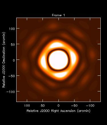
16 Implications for imaging: Wide-field effects I = PSF I PB Errors are due to time-varying Primary Beam Errors are directionally dependent Imaging performances of the telescope is limited by these errors (and not the thermal noise) 16/52
17 Implications for imaging: Wide-band effects 3C286 field Sp.Ndx=-0.47 BW = 1.1 GHz Conventional imaging - Frequency oblivious Image model DR = /52
18 Implications for imaging: Computing To keep time and band width smearing errors below thermal limit for wide FoV, needs finer sampling in time and frequency. Data volume N2ant Nchannels Nt Nchannels = 1-10GHz/KHz-MHz Nant and Nt = 10hr/(1-10sec) = 27 (EVLA), ~50 (ALMA), Cast of thousands (SKA) x increase in the number of samples to achieve the required sensitivities Algorithm efficiency remains a critical parameter Algorithms for wide-field and wide-band effects require more floating point operations (FLOP) Inherent information content in the data is higher Need computing platforms with (much) higher I/O rates and FLOPS (FLOP per sec) capacity....and larger RAM (possibly) 18/52
19 Parametrization of the ME Lower the number of parameters in the model that leaves noise-like residuals, higher is the information extracted. Papers on Information Theory (possibly by Donoho, 2000) Models in the Natural Domain of the information one seeks minimizes the number of parameters Image domain: Natural Domain for sky-emission Structure Frequency and polarization dependence Visibility Domain: Natural Domain for instrumental effects PB effects Electronics gains, etc. 19/52
20 Parametrized model for sky emission Obs S 2 bij. s V ij = M ij, t W ij M ij s,, t I s, e ds The function I(s) represent sky emission Information it represents is inherently in the sky domain Parametrize structure: Asp-Clean, MS-Clean Parametrize frequency dependence: MS-MFS Image Domain Visibility Domain 20/52
 represent sky emission Information it")

21 Parametrized model for sky emission Obs S 2 bij. s V ij = M ij, t W ij M ij s,, t I s, e ds The function I(s) represent sky emission Information it represents is inherently in the sky domain Parametrize structure: Asp-Clean, MS-Clean Parametrize frequency dependence: MS-MFS M 4 I = k A k NComps=10 x x k Image Domain 3 M I = k A k f NComps=10 Scale, Pos. Visibility Domain Better parametrization in the Natural Domain 21/52
 represent sky")

22 Parametrized model for sky emission Obs 2 bij. s S V ij = M ij, t W ij M ij s,, t I s, e ds The function I(s) represent sky emission Information it represents is inherently in the sky domain Parametrize structure: Asp-Clean, MS-Clean Parametrize frequency dependence: MS-MFS 4.0GHz Sp. Ndx 1.0GHz Rau, PhDThesis, /52
23 Wide-band imaging: Multi-Term MFS 3C286 field Sp.Ndx=-0.47 BW = 1.1 GHz DR = /52
24 Wide-band imaging: Multi-Term MFS MT-MFS: Collection of components whose amplitude follow a polynomial in frequency 3C286 field Sp.Ndx=-0.47 BW = 1.1 GHz Multi-term MFS Nterm = 2 DR = /52
25 Wide-band imaging: Multi-Term MFS 3C286 field Sp.Ndx=-0.47 BW = 1.1 GHz Multi-term MFS Nterm = 4 DR = 110, ,000 25/52
![Wide-band Stokes-I imaging: MS+MTMFS The sky emission varies with frequency Frequency dependence is also directionally dependent [ D I = PSF PB I Sky ] =](/docs-images/92/109729176/images/26-0.jpg "2.7 = 1.1 Need: MS: For extended emission + MT-MFS: For DD Sp.Ndx. + W-Term correction + WB PB-correction 2.9 = 0.9 3.")
26 Wide-band Stokes-I imaging: MS+MTMFS The sky emission varies with frequency Frequency dependence is also directionally dependent [ D I = PSF PB I Sky ] = 2.7 = 1.1 Need: MS: For extended emission + MT-MFS: For DD Sp.Ndx. + W-Term correction + WB PB-correction 2.9 = MS-MFS; Rau, PhDThesis, /52
27 Wide-band Spectral Index Imaging: MS+MT MFS Spectral Index map = 2.7 = = 0.9 Need: MS: For extended emission + MT-MFS: For DD Sp.Ndx. + W-Term correction + WB PB-correction 3.2 MS-MFS; Rau, PhDThesis, /52

28 Wide-field Imaing: PB effects The observed data corresponds to Isky multiplied by the antenna primary beam D [ I = t PSF, t PB s, t I Sky ] PB varies with time due to rotation with PA and pointing errors. PB gain in general is also Directionally Dependent 28/52
 One element of the Sky-Jones (Jones Matrix per pixel) A-Projection is the first")
29 The A-Projection algorithm V o u, v, w =V M u, v J i u, v ; s J j u, v ;s Modified forward and reverse transforms: No assumption about sky properties Spatial, time, frequency and polarization dependence naturally accounted for Done at approximately FFT speed Model for EVLA aperture illumination (real part) One element of the Sky-Jones (Jones Matrix per pixel) A-Projection is the first term of the series expansion of the Aperture Illumination pattern. A u = Ao u [1 a o Z o u...] Projection formulation delivers efficient solvers to solve for parametrized models (Pointing SelfCal and its extensions) A-Projection algorithm, A&A /52


30 A-Projection algorithm: Simulations Before Correction After Correction Minimize : V Oij Eij [ F I M ] w.r.t. I M Goal: Full-field, full-polarization imaging at full-sensitivity A-Projection: Bhatnagar et al., A&A,487, /52
31 EVLA L-Band Stokes-I: Before correction 3C147 field at L-Band Dynamic range: ~700,000:1 A single baseline based correction was applied 31/52
32 EVLA L-Band Stokes-I: After correction 3C147 field at L-Band with the EVLA Only 12 antennas used Bandwidth: 128 MHz ~7 hr. integration Dynamic range: ~700,000:1 32/52
33 EVLA L-Band Stokes-V: Before correction Is it M s, Poln? Or is it I s, Poln? 2 b ij. s S V Obs = M M s I s e ij ij ij ds 33/52
34 EVLA L-Band Stokes-I: After correction Use physical model for the Stokes-V pattern: Contours: Stokes-I power pattern Colour: Stokes-V power pattern 34/52
35 Parametrized model for aperture illumination 2 bij. s S V Obs = M, t W M s,, t I s, e ij ij ij ij ds Instrumental effects are fundamentally antenna-based S M ij represents information inherently in the visibility domain S Image domain: Only average M ij is available Difficult to handle the case of non-identical antennas Visibility Domain: Remains separable as antenna-based terms FT M S = FT J FT J T [ ] ij [ ] i [ ] Opens up algorithms for DD corrections, calibration,... 35/52


![I = t PSF PB s, t, I Sky ] PB in general is rotation](/docs-images/92/109729176/images/36-2.jpg "asymmetric Frequency dependence of the PB is also")
36 Implications for imaging: Wide-band effects To the first order, antenna primary beams scale with frequency E.g., size of the PB changes 2x for EVLA bandwidths D [ I = t PSF PB s, t, I Sky ] PB in general is rotation asymmetric Frequency dependence of the PB is also directionally dependent PB Spectral Index 36/52


37 Time Direction/Freq Time Time Aperture Plane Image Plane Time varying DD gains due to PB Freq 37/52
![Extension to mosaicking V Obs = S ij t Aij, t V ij [ ] In the data domain, PB effects correspond to convolution - It is included as part of the convolutional gridding operation for Projection](/docs-images/92/109729176/images/38-0.jpg "algorithms Mosaicking, polarization squint, pointing errors, etc.")
38 Extension to mosaicking V Obs = S ij t Aij, t V ij [ ] In the data domain, PB effects correspond to convolution - It is included as part of the convolutional gridding operation for Projection algorithms Mosaicking, polarization squint, pointing errors, etc. are a matter of putting the correct phase gradient Aij= Ai * Aj : The functions can be computed in a antenna dependent manner Naturally accounts for heterogeneous arrays (ALMA) DD calibration algorithms can be designed to modify Ai to fit the data (e.g. Pointing SelfCal). 38/52
 ~25 microjy/beam RSRO Projects (AB1345, Bhatnagar et al.")
39 Wide-field wide-band imaging with the EVLA PB 50% point GHz (4x128 MHz) ~25 microjy/beam RSRO Projects (AB1345, Bhatnagar et al.) Scientific goals - Spectral Index imaging - RM Synthesis - Wide-band, wide-field imaging - HPC 39/52
40 Effect of antenna pointing errors A Effect of antenna pointing error is a direction dependent effect A purely Hermitian effect in the data domain, in the absence of DI gains To the first order, amplitude-only error in image domain However, there is significant in-beam phase structure particularly for wide-field, full-stokes imaging B 40/52
41 Effect of antenna pointing errors Effect of antenna pointing error is a direction dependent effect A purely Hermitian effect in the data domain, in the absence of DI gains To the first order, amplitude-only error in image domain Faceting approach: Solve for gains for A and B separately Interpolate in between Pointing SelfCal Solve for the shape of the function which best-fits the gain variations at A and B A B Pointing error 41/52
42 DD SelfCal algorithm: EVLA Data El-Az mount antennas Polarization squint due to off-axis feeds - The R- and L-beam patterns have a pointing R-beam error of +/- ~0.06 Pointing error R-beam Pointing error D DoF used: 2 per antenna SNR available for more DoF to model the PB shape L-beam L-beam EVLA polarization squint solved as pointing error (optical pointing error). Squint would be symmetric about the origin in El-Az plane in the absence of antenna servo pointing errors. Pointing errors for various antennas detected in the range 1-7 arcmin. Pointing errors confirmed independently via the EVLA online system. [paper in preparation] 42/52
43 DD SelfCal: General comments Pointing SelfCal formulation is generalization of DI SelfCal M Standard SelfCal (DI): V ij = G i G j V ij Pointing SelfCal: V ij = J Si J Sj V Mij Effects of PB/antenna pointing is purely Hermitian in the data domain in the absence of DI gains or in-beam phase etc. I.e., amp-only effect in the image plane Fundamentally an antenna based effect Difficult to decouple/interpret in the image plane Fundamentally a data-domain effect Not an image plane effect Unlike, e.g., effects of sky spectral index variations (a DD error) Clean works, but scale-sensitive methods work better Similarly, Partitioning/SelfCal works, but DD SelfCal should work better! 43/52
44 I/O load Recent data with the EVLA: GB Expect passes through the data (flagging + calibration + imaging + human errors) Effective data i/o: few TB Typical disk I/O rates: MB/s Exploit data parallelism Distribute normal equations (SPMD paradigm) Deploy computationally efficient algorithms ( P of SPMD) on a cluster 44/52
45 Computing load More data samples used for imaging Few X frequency channels 1-30 sec. Integration intervals More computing per gridding/de-gridding Convolution support size increase for W- and A-Projection More images made for Multi-term MFS Each term constitutes full gridding/de-gridding load Various optimization possible to balance between memory footprint and computing footprint Most operations are embarrassingly parallel 45/52
46 Cluster Computing Local Store (Disk/RAM) dms, dms, di di dms, di dms, Interconnect di dms, dms, di di Controller node Big disk MS Goal: CPU Bound Processing Gridding/de-gridding on each node using a subset of the data Data fed through a high speed link to fast-disk (Lustre) - 10 MB/s per node Multiple processes per node Asynchronous I/O - A single thread per node does read-ahead - Processing becomes CPU bound Golap, Robnett, Jacobs, Kern 46/52
47 Parallelization: Initial results 47/52
48 Parallelization: Initial results Continuum imaging: (No PB-correction or MFS) Requires inter-node I/O (Distribution of normal equations) 4-6x speed-up using 8-cores per node I/O bound without async-i/o Expected close to linear speed-up with async-i/o - Async-I/O in the process of being deployed Work in progress Calibration: Gain, Bandpass, polarization Flagging: simple flagging + possibly auto-flagging Self-Cal Simple data visualization 48/52
49 Summary Modeling various terms in the Natural Domain of information they represent W-Term, Antenna Aperture effects in the visibility domain Extended emission, sky frequency- and polarizationdependence in the image domain W-Projection, WB A-Projection Use in mosaicking as well MS-MFS, Asp, RM-Synthesis Developing DD solvers to solve for for low-order models for Aperture illumination Pointing SelfCal and beyond 49/52

 Re-worked the code to enable Wide-band A-Projection Heterogeneous arrays (ALMA) Next steps: WB")
50 What keeps us busy? Shooting for full-sensitivity full-polarization wide-band imaging Bug discovery and fixes (many thanks to FO, CC, JM-J, EF, JU,...) Re-worked the code to enable Wide-band A-Projection Heterogeneous arrays (ALMA) Next steps: WB A-Projection + W-Projection Integrate MS-MFS and WB A-Projection Extend to mosaic imaging Extend to full-polarization Integrate with RM-synthesis D. Petry, ESO 50/52
51 What keeps us busy? Projects in various stages of R&D Automatic RFI detection/removal Pointing SelfCal An issues for ALMA and mosaicking in general Asp-Clean based MFS, RM-Synthesis(?) 1. Memory foot-print 2. Reduce error bars on Spectral Index images Integrate with parallel computing framework for deployment on HPC platforms Multi-threading where possible (e.g. minor cycle) Develop pipelines or integrate with existing pipeline processing framework 51/52
52 Thanks Various testers of the bleeding-edge code Various members of the EVLA commissioning team Computing Staff CASA team Various people whose brain I often borrow... 52/52
53 Era of Data Deluge My reaction to Data Deluge skeptics Beginning of telephone era: People reported shock lasting days after a phone call Much opposition is simply romantic Mathematics Tells us Information technology is not magic Extracting information from data is not a sure thing Specific hard work on a case-by-case basis You can learn what must be done Data! Data! Data! Challenges and opportunities of the coming Data Deluge - David Dohono, Stanford Univ. USNA Michelson Lecture, /52
Components of Imaging at Low Frequencies: Status & Challenges
 Components of Imaging at Low Frequencies: Status & Challenges Dec. 12th 2013 S. Bhatnagar NRAO Collaborators: T.J. Cornwell, R. Nityananda, K. Golap, U. Rau J. Uson, R. Perley, F. Owen Telescope sensitivity
Recent progress in EVLA-specific algorithms. EVLA Advisory Committee Meeting, March 19-20, S. Bhatnagar and U. Rau
 Recent progress in EVLA-specific algorithms EVLA Advisory Committee Meeting, March 19-20, 2009 S. Bhatnagar and U. Rau Imaging issues Full beam, full bandwidth, full Stokes noise limited imaging Algorithmic
Wide Bandwidth Imaging
 Wide Bandwidth Imaging 14th NRAO Synthesis Imaging Workshop 13 20 May, 2014, Socorro, NM Urvashi Rau National Radio Astronomy Observatory 1 Why do we need wide bandwidths? Broad-band receivers => Increased
Plan for Imaging Algorithm Research and Development
 Plan for Imaging Algorithm Research and Development S. Bhatnagar July 05, 2009 Abstract Many scientific deliverables of the next generation radio telescopes require wide-field imaging or high dynamic range
Wide-field, wide-band and multi-scale imaging - II
 Wide-field, wide-band and multi-scale imaging - II Radio Astronomy School 2017 National Centre for Radio Astrophysics / TIFR Pune, India 28 Aug 8 Sept, 2017 Urvashi Rau National Radio Astronomy Observatory,
Wide-Band Imaging. Outline : CASS Radio Astronomy School Sept 2012 Narrabri, NSW, Australia. - What is wideband imaging?
 Wide-Band Imaging 24-28 Sept 2012 Narrabri, NSW, Australia Outline : - What is wideband imaging? - Two Algorithms Urvashi Rau - Many Examples National Radio Astronomy Observatory Socorro, NM, USA 1/32
EVLA and LWA Imaging Challenges
 EVLA and LWA Imaging Challenges Steven T. Myers IGPP, Los Alamos National Laboratory and National Radio Astronomy Observatory, Socorro, NM 1 EVLA key issues 2 Key algorithmic issues ambitious goals / hard
Recent imaging results with wide-band EVLA data, and lessons learnt so far
 Recent imaging results with wide-band EVLA data, and lessons learnt so far Urvashi Rau National Radio Astronomy Observatory (USA) 26 Jul 2011 (1) Introduction : Imaging wideband data (2) Wideband Imaging
Introduction to Imaging in CASA
 Introduction to Imaging in CASA Mark Rawlings, Juergen Ott (NRAO) Atacama Large Millimeter/submillimeter Array Expanded Very Large Array Robert C. Byrd Green Bank Telescope Very Long Baseline Array Overview
GPU based imager for radio astronomy
 GPU based imager for radio astronomy GTC2014, San Jose, March 27th 2014 S. Bhatnagar, P. K. Gupta, M. Clark, National Radio Astronomy Observatory, NM, USA NVIDIA-India, Pune NVIDIA-US, CA Introduction
Imaging and Calibration Algorithms for EVLA, e-merlin and ALMA. Robert Laing ESO
 Imaging and Calibration Algorithms for EVLA, e-merlin and ALMA Socorro, April 3 2008 Workshop details Oxford, 2008 Dec 1-3 Sponsored by Radionet and the University of Oxford 56 participants http://astrowiki.physics.ox.ac.uk/cgi-bin/twiki/view/algorithms2008/webhome
Fourier Transforms in Radio Astronomy
 Fourier Transforms in Radio Astronomy Kavilan Moodley, UKZN Slides taken from N Gupta s lectures: SKA School 2013 van-cittert Zernike theorem Extended, quasi-monochromatic, incoherent source X (l,m) Y
High Fidelity Imaging of Extended Sources. Rick Perley NRAO Socorro, NM
 High Fidelity Imaging of Extended Sources Rick Perley NRAO Socorro, NM A Brief History of Calibration (VLA) An Amazing Fact: The VLA was proposed, and funded, without any real concept of how to calibrate
Phased Array Feeds A new technology for multi-beam radio astronomy
 Phased Array Feeds A new technology for multi-beam radio astronomy Aidan Hotan ASKAP Deputy Project Scientist 2 nd October 2015 CSIRO ASTRONOMY AND SPACE SCIENCE Outline Review of radio astronomy concepts.
Radio Astronomy: SKA-Era Interferometry and Other Challenges. Dr Jasper Horrell, SKA SA (and Dr Oleg Smirnov, Rhodes and SKA SA)
") Radio Astronomy: SKA-Era Interferometry and Other Challenges Dr Jasper Horrell, SKA SA (and Dr Oleg Smirnov, Rhodes and SKA SA) ASSA Symposium, Cape Town, Oct 2012 Scope SKA antenna types Single dishes
Radio Astronomy: SKA-Era Interferometry and Other Challenges Dr Jasper Horrell, SKA SA (and Dr Oleg Smirnov, Rhodes and SKA SA) ASSA Symposium, Cape Town, Oct 2012 Scope SKA antenna types Single dishes
EVLA Memo 146 RFI Mitigation in AIPS. The New Task UVRFI
 EVLA Memo 1 RFI Mitigation in AIPS. The New Task UVRFI L. Kogan, F. Owen 1 (1) - National Radio Astronomy Observatory, Socorro, New Mexico, USA June, 1 Abstract Recently Ramana Athrea published a new algorithm
When, why and how to self-cal Nathan Brunetti, Crystal Brogan, Amanda Kepley
 When, why and how to self-cal Nathan Brunetti, Crystal Brogan, Amanda Kepley Atacama Large Millimeter/submillimeter Array Expanded Very Large Array Robert C. Byrd Green Bank Telescope Very Long Baseline
Adaptive selective sidelobe canceller beamformer with applications in radio astronomy
 Adaptive selective sidelobe canceller beamformer with applications in radio astronomy Ronny Levanda and Amir Leshem 1 Abstract arxiv:1008.5066v1 [astro-ph.im] 30 Aug 2010 We propose a new algorithm, for
LOFAR: From raw visibilities to calibrated data
 Netherlands Institute for Radio Astronomy LOFAR: From raw visibilities to calibrated data John McKean (ASTRON) [subbing in for Manu] ASTRON is part of the Netherlands Organisation for Scientific Research
How small can you get? reducing data volume, retaining good imaging
 How small can you get? reducing data volume, retaining good imaging Anita Richards UK ALMA Regional Centre Jodrell Bank Centre for Astrophysics University of Manchester thanks to Crystal Brogan and all
Atacama Large Millimeter/submillimeter Array Expanded Very Large Array Robert C. Byrd Green Bank Telescope Very Long Baseline Array
 Atacama Large Millimeter/submillimeter Array Expanded Very Large Array Robert C. Byrd Green Bank Telescope Very Long Baseline Array Self-Calibration Ed Fomalont (NRAO) ALMA Data workshop Dec. 2, 2011 Atacama
Applying full polarization A-Projection to very-wide fields of view instruments: An imager for LOFAR Cyril Tasse
 Applying full polarization A-Projection to very-wide fields of view instruments: An imager for LOFAR Cyril Tasse ASTRON/Leiden: Joris van Zwieten, Bas van der Tol, Ger van Diepen NRAO: Sanjay Bhatnagar
Parameterized Deconvolution for Wide-Band Radio Synthesis Imaging
 Parameterized Deconvolution for Wide-Band Radio Synthesis Imaging Urvashi Rao Venkata Ph.D. Thesis Defense Department of Physics, New Mexico Institute of Mining and Technology 17 May 2010 Advisors / Committee
THEORY OF MEASUREMENTS
 THEORY OF MEASUREMENTS Brian Mason Fifth NAIC-NRAO School on Single-Dish Radio Astronomy Arecibo, PR July 2009 OUTLINE Antenna-Sky Coupling Noise the Radiometer Equation Minimum Tsys Performance measures
Basic Mapping Simon Garrington JBO/Manchester
 Basic Mapping Simon Garrington JBO/Manchester Introduction Output from radio arrays (VLA, VLBI, MERLIN etc) is just a table of the correlation (amp. & phase) measured on each baseline every few seconds.
LOFAR: Special Issues
 Netherlands Institute for Radio Astronomy LOFAR: Special Issues John McKean (ASTRON) ASTRON is part of the Netherlands Organisation for Scientific Research (NWO) 1 Preamble http://www.astron.nl/~mckean/eris-2011-2.pdf
Presented by James Aguirre University of Pennsylvania 26 March 2013 SKA1 Low Workshop
 Presented by James Aguirre University of Pennsylvania 26 March 2013 SKA1 Low Workshop UVa / NRAO Bradley Carilli Klima Gugliucci Parashare The PAPER Team UC Berkeley Parsons Pober Ali De Boer MacMahon
Very Long Baseline Interferometry
 Very Long Baseline Interferometry Cormac Reynolds, JIVE European Radio Interferometry School, Bonn 12 Sept. 2007 VLBI Arrays EVN (Europe, China, South Africa, Arecibo) VLBA (USA) EVN + VLBA coordinate
What is CASA? Rachel Friesen. North American ALMA Science Center. Victoria BC, January 18, 2011 ALMA Software Tutorial 1
 What is CASA? Rachel Friesen North American ALMA Science Center Victoria BC, January 18, 2011 ALMA Software Tutorial 1 Outline Introduction and Current Status General tools and tasks CASA in use! CASA
Data processing with the RTS A GPU-accelerated calibration & imaging stream processor
 Data processing with the RTS A GPU-accelerated calibration & imaging stream processor Daniel Mitchell 2018 ICRAR/CASS Radio School CSIRO ASTRONOMY AND SPACE SCIENCE The RTS (Real-Time System) A GPU-accelerated
Phased Array Feeds A new technology for wide-field radio astronomy
 Phased Array Feeds A new technology for wide-field radio astronomy Aidan Hotan ASKAP Project Scientist 29 th September 2017 CSIRO ASTRONOMY AND SPACE SCIENCE Outline Review of radio astronomy concepts
Imaging Simulations with CARMA-23
 BIMA memo 101 - July 2004 Imaging Simulations with CARMA-23 M. C. H. Wright Radio Astronomy laboratory, University of California, Berkeley, CA, 94720 ABSTRACT We simulated imaging for the 23-antenna CARMA
Error Recognition Emil Lenc (and Arin)
") Error Recognition Emil Lenc (and Arin) University of Sydney / CAASTRO www.caastro.org CASS Radio Astronomy School 2017 Based on lectures given previously by Ron Ekers and Steven Tingay CSIRO; Swinburne
Error Recognition Emil Lenc (and Arin) University of Sydney / CAASTRO www.caastro.org CASS Radio Astronomy School 2017 Based on lectures given previously by Ron Ekers and Steven Tingay CSIRO; Swinburne
ESO/ALBiUS activities in ALMA imaging with CASA
 ESO/ALBiUS activities in ALMA imaging with CASA Dirk Petry (ESO), August 2010 Outline ALMA Overview ALMA CALIM challenges CASA status Ongoing work at ESO 1 ALMA Overview The Atacama Large Mm/sub-mm Array
Special Topics: AIPS. 24 February 2012 Socorro, NM USA. Eric Greisen. Robert C. Byrd Green Bank Telescope
 Special Topics: AIPS 4 February 01 Socorro, NM USA Eric Greisen Atacama Large Millimeter/submillimeter Array Expanded Very Large Array Robert C. Byrd Green Bank Telescope Very Long Baseline Array Outline
Volume 82 VERY LONG BASELINE INTERFEROMETRY AND THE VLBA. J. A. Zensus, P. J. Diamond, and P. J. Napier
 ASTRONOMICAL SOCIETY OF THE PACIFIC CONFERENCE SERIES Volume 82 VERY LONG BASELINE INTERFEROMETRY AND THE VLBA Proceedings of a Summer School held in Socorro, New Mexico 23-30 June 1993 NRAO Workshop No.
images with ASKAP Max Voronkov ASKAP So(ware scien1st 20 November 2012 Astronomy and Space Science
 Making images with ASKAP Max Voronkov ASKAP So(ware scien1st 20 November 2012 Astronomy and Space Science Australian Square Kilometre Array Pathfinder Radio interferometer with 36 iden1cal 12m antennas
Mosaicking. Brian Mason (NRAO) Sixteenth Synthesis Imaging Workshop May 2018
 Sixteenth Synthesis Imaging Workshop May 2018") Mosaicking Brian Mason (NRAO) Sixteenth Synthesis Imaging Workshop 16-23 May 2018 The simplest observing scenario for an interferometer: Source at known location Size
Mosaicking Brian Mason (NRAO) Sixteenth Synthesis Imaging Workshop 16-23 May 2018 The simplest observing scenario for an interferometer: Source at known location Size
Interferometry I Parkes Radio School Jamie Stevens ATCA Senior Systems Scientist
 Interferometry I Parkes Radio School 2011 Jamie Stevens ATCA Senior Systems Scientist 2011-09-28 References This talk will reuse material from many previous Radio School talks, and from the excellent textbook
Fundamentals of Interferometry
 Fundamentals of Interferometry ERIS, Dwingeloo, Sept 8-13 2013 Outline What is an interferometer? Basic theory Interlude: Fourier transforms for birdwatchers Review of assumptions and complications Interferometers
Spectral Line II: Calibration and Analysis. Spectral Bandpass: Bandpass Calibration (cont d) Bandpass Calibration. Bandpass Calibration
 Bandpass Calibration. Bandpass Calibration") Spectral Line II: Calibration and Analysis Bandpass Calibration Flagging Continuum Subtraction Imaging Visualization Analysis Spectral Bandpass: Spectral frequency response of antenna to a spectrally flat
Spectral Line II: Calibration and Analysis Bandpass Calibration Flagging Continuum Subtraction Imaging Visualization Analysis Spectral Bandpass: Spectral frequency response of antenna to a spectrally flat
SKA Phase 1: Costs of Computation. Duncan Hall CALIM 2010
 SKA Phase 1: Costs of Computation Duncan Hall CALIM 2010 2010 August 24, 27 Outline Motivation Phase 1 in a nutshell Benchmark from 2001 [EVLA Memo 24] Some questions Amdahl s law overrides Moore s law!
2010 PASEO Meeting. CASA: Common Astronomy Software Applications. July 15-16, 2010 Socorro, NM. Steven T. Myers (EVLA CASA Subsystem Scientist)
") 2010 PASEO Meeting July 15-16, 2010 Socorro, NM CASA: Common Astronomy Software Applications Steven T. Myers (EVLA CASA Subsystem Scientist) Atacama Large Millimeter/submillimeter Array Expanded Very Large
2010 PASEO Meeting July 15-16, 2010 Socorro, NM CASA: Common Astronomy Software Applications Steven T. Myers (EVLA CASA Subsystem Scientist) Atacama Large Millimeter/submillimeter Array Expanded Very Large
REDUCTION OF ALMA DATA USING CASA SOFTWARE
 REDUCTION OF ALMA DATA USING CASA SOFTWARE Student: Nguyen Tran Hoang Supervisor: Pham Tuan Anh Hanoi, September - 2016 1 CONTENS Introduction Interferometry Scientific Target M100 Calibration Imaging
Calibration. (in Radio Astronomy) Ishwara Chandra CH NCRA-TIFR. Acknowledgments:
 Ishwara Chandra CH NCRA-TIFR. Acknowledgments:") Calibration (in Radio Astronomy) Ishwara Chandra CH NCRA-TIFR Acknowledgments: Synthesis Imaging in Radio Astronomy II: Chapter 5 Low Frequency Radio Astronomy (blue book): Chapter 5 Calibration and Advanced
Calibration (in Radio Astronomy) Ishwara Chandra CH NCRA-TIFR Acknowledgments: Synthesis Imaging in Radio Astronomy II: Chapter 5 Low Frequency Radio Astronomy (blue book): Chapter 5 Calibration and Advanced
Spectral Line Observing
 Spectral Line Observing Ylva Pihlström, UNM Eleventh Synthesis Imaging Workshop Socorro, June 10-17, 2008 Introduction 2 Spectral line observers use many channels of width δν, over a total bandwidth Δν.
Why? When? How What to do What to worry about
 Tom Muxlow Data Combination Why? When? How What to do What to worry about Combination imaging or separate imaging??..using (e-)merlin (e-)merlin covers a unique range of telescope separations, intermediate
Sideband Smear: Sideband Separation with the ALMA 2SB and DSB Total Power Receivers
 and DSB Total Power Receivers SCI-00.00.00.00-001-A-PLA Version: A 2007-06-11 Prepared By: Organization Date Anthony J. Remijan NRAO A. Wootten T. Hunter J.M. Payne D.T. Emerson P.R. Jewell R.N. Martin
The Basics of Radio Interferometry. Frédéric Boone LERMA, Observatoire de Paris
 The Basics of Radio Interferometry LERMA, Observatoire de Paris The Basics of Radio Interferometry The role of interferometry in astronomy = role of venetian blinds in Film Noir 2 The Basics of Radio Interferometry
INTERFEROMETRY: II Nissim Kanekar (NCRA TIFR)
") INTERFEROMETRY: II Nissim Kanekar (NCRA TIFR) WSRT GMRT VLA ATCA ALMA SKA MID PLAN Introduction. The van Cittert Zernike theorem. A 2 element interferometer. The fringe pattern. 2 D and 3 D interferometers.
INTERFEROMETRY: II Nissim Kanekar (NCRA TIFR) WSRT GMRT VLA ATCA ALMA SKA MID PLAN Introduction. The van Cittert Zernike theorem. A 2 element interferometer. The fringe pattern. 2 D and 3 D interferometers.
Phased Array Feeds & Primary Beams
 Phased Array Feeds & Primary Beams Aidan Hotan ASKAP Deputy Project Scientist 3 rd October 2014 CSIRO ASTRONOMY AND SPACE SCIENCE Outline Review of parabolic (dish) antennas. Focal plane response to a
EVLA Scientific Commissioning and Antenna Performance Test Check List
 EVLA Scientific Commissioning and Antenna Performance Test Check List C. J. Chandler, C. L. Carilli, R. Perley, October 17, 2005 The following requirements come from Chapter 2 of the EVLA Project Book.
Large-field imaging. Frédéric Gueth, IRAM Grenoble. 7th IRAM Millimeter Interferometry School 4 8 October 2010
 Large-field imaging Frédéric Gueth, IRAM Grenoble 7th IRAM Millimeter Interferometry School 4 8 October 2010 Large-field imaging The problems The field of view is limited by the antenna primary beam width
EVLA System Commissioning Results
 EVLA System Commissioning Results EVLA Advisory Committee Meeting, March 19-20, 2009 Rick Perley EVLA Project Scientist t 1 Project Requirements EVLA Project Book, Chapter 2, contains the EVLA Project
Self-calibration. Elisabetta Liuzzo Rosita Paladino
 Elisabetta Liuzzo Rosita Paladino Why self-calibration works When it is possible to self-calibrate in practice Calibration using external calibrators in not perfect interpolated from different time, different
Fundamentals of Radio Interferometry
 Fundamentals of Radio Interferometry Rick Perley, NRAO/Socorro Fourteenth NRAO Synthesis Imaging Summer School Socorro, NM Topics Why Interferometry? The Single Dish as an interferometer The Basic Interferometer
March Phased Array Technology. Andrew Faulkner
 Aperture Arrays Michael Kramer Sparse Type of AA selection 1000 Sparse AA-low Sky Brightness Temperature (K) 100 10 T sky A eff Fully sampled AA-mid Becoming sparse Aeff / T sys (m 2 / K) Dense A eff /T
Heterogeneous Array Imaging with the CARMA Telescope
 Heterogeneous Array Imaging with the CARMA Telescope M. C. H. Wright Radio Astronomy laboratory, University of California, Berkeley, CA, 94720 February 1, 2011 ACKNOWLEDGMENTS Many people have made the
Introduction to interferometry with bolometers: Bob Watson and Lucio Piccirillo
 Introduction to interferometry with bolometers: Bob Watson and Lucio Piccirillo Paris, 19 June 2008 Interferometry (heterodyne) In general we have i=1,...,n single dishes (with a single or dual receiver)
Correlator Development at Haystack. Roger Cappallo Haystack-NRAO Technical Mtg
 Correlator Development at Haystack Roger Cappallo Haystack-NRAO Technical Mtg. 2006.10.26 History of Correlator Development at Haystack ~1973 Mk I 360 Kb/s x 2 stns. 1981 Mk III 112 Mb/s x 4 stns. 1986
Next Generation Very Large Array Memo No. 16 More on Synthesized Beams and Sensitivity. C.L. Carilli, NRAO, PO Box O, Socorro, NM
 Next Generation Very Large Array Memo No. 16 More on Synthesized Beams and Sensitivity C.L. Carilli, NRAO, PO Box O, Socorro, NM Abstract I present further calculations on synthesized beams and sensitivities
May AA Communications. Portugal
 SKA Top-level description A large radio telescope for transformational science Up to 1 million m 2 collecting area Operating from 70 MHz to 10 GHz (4m-3cm) Two or more detector technologies Connected to
Towards SKA Multi-beam concepts and technology
 Towards SKA Multi-beam concepts and technology SKA meeting Meudon Observatory, 16 June 2009 Philippe Picard Station de Radioastronomie de Nançay philippe.picard@obs-nancay.fr 1 Square Kilometre Array:
Real Time Imaging. Melvyn Wright. Radio Astronomy Laboratory, University of California, Berkeley, CA, ABSTRACT
 SKA MEMO 60, 24 May 2005 Real Time Imaging Melvyn Wright Radio Astronomy Laboratory, University of California, Berkeley, CA, 94720 ABSTRACT In this paper, we propose to integrate the imaging process with
EVLA Memo #119 Wide-Band Sensitivity and Frequency Coverage of the EVLA and VLA L-Band Receivers
 EVLA Memo #119 Wide-Band Sensitivity and Frequency Coverage of the EVLA and VLA L-Band Receivers Rick Perley and Bob Hayward January 17, 8 Abstract We determine the sensitivities of the EVLA and VLA antennas
Introduction to Radio Astronomy!
 Introduction to Radio Astronomy! Sources of radio emission! Radio telescopes - collecting the radiation! Processing the radio signal! Radio telescope characteristics! Observing radio sources Sources of
Introduction to Radio Interferometry Sabrina Stierwalt Alison Peck, Jim Braatz, Ashley Bemis
 Introduction to Radio Interferometry Sabrina Stierwalt Alison Peck, Jim Braatz, Ashley Bemis Atacama Large Millimeter/submillimeter Array Expanded Very Large Array Robert C. Byrd Green Bank Telescope Very
Radio Interferometry. Xuening Bai. AST 542 Observational Seminar May 4, 2011
 Radio Interferometry Xuening Bai AST 542 Observational Seminar May 4, 2011 Outline Single-dish radio telescope Two-element interferometer Interferometer arrays and aperture synthesis Very-long base line
Smart Antennas in Radio Astronomy
 Smart Antennas in Radio Astronomy Wim van Cappellen cappellen@astron.nl Netherlands Institute for Radio Astronomy Our mission is to make radio-astronomical discoveries happen ASTRON is an institute for
Radio Interferometers Around the World. Amy J. Mioduszewski (NRAO)
") Radio Interferometers Around the World Amy J. Mioduszewski (NRAO) A somewhat biased view of current interferometers Limited to telescopes that exist or are in the process of being built (i.e., I am not
Radio Interferometers Around the World Amy J. Mioduszewski (NRAO) A somewhat biased view of current interferometers Limited to telescopes that exist or are in the process of being built (i.e., I am not
Overview of the SKA. P. Dewdney International SKA Project Engineer Nov 9, 2009
 Overview of the SKA P. Dewdney International SKA Project Engineer Nov 9, 2009 Outline* 1. SKA Science Drivers. 2. The SKA System. 3. SKA technologies. 4. Trade-off space. 5. Scaling. 6. Data Rates & Data
A model for the SKA. Melvyn Wright. Radio Astronomy laboratory, University of California, Berkeley, CA, ABSTRACT
 SKA memo 16. 21 March 2002 A model for the SKA Melvyn Wright Radio Astronomy laboratory, University of California, Berkeley, CA, 94720 ABSTRACT This memo reviews the strawman design for the SKA telescope.
Fundamentals of Radio Interferometry. Robert Laing (ESO)
") Fundamentals of Radio Interferometry Robert Laing (ESO) 1 ERIS 2015 Objectives A more formal approach to radio interferometry using coherence functions A complementary way of looking at the technique Simplifying
Fundamentals of Radio Interferometry Robert Laing (ESO) 1 ERIS 2015 Objectives A more formal approach to radio interferometry using coherence functions A complementary way of looking at the technique Simplifying
Practicalities of Radio Interferometry
 Practicalities of Radio Interferometry Rick Perley, NRAO/Socorro 13 th Synthesis Imaging Summer School 29 May 5 June, 2012 Socorro, NM Topics Practical Extensions to the Theory: Finite bandwidth Rotating
Fundamentals of Interferometry
 Fundamentals of Interferometry ERIS, Rimini, Sept 5-9 2011 Outline What is an interferometer? Basic theory Interlude: Fourier transforms for birdwatchers Review of assumptions and complications Interferometers
Antennas. Greg Taylor. University of New Mexico Spring Astronomy 423 at UNM Radio Astronomy
 Antennas Greg Taylor University of New Mexico Spring 2017 Astronomy 423 at UNM Radio Astronomy Outline 2 Fourier Transforms Interferometer block diagram Antenna fundamentals Types of antennas Antenna performance
Commissioning Report for the ATCA L/S Receiver Upgrade Project
 Commissioning Report for the ATCA L/S Receiver Upgrade Project N. M. McClure-Griffiths, J. B. Stevens, & S. P. O Sullivan 8 June 211 1 Introduction The original Australia Telescope Compact Array (ATCA)
ATCA Antenna Beam Patterns and Aperture Illumination
 1 AT 39.3/116 ATCA Antenna Beam Patterns and Aperture Illumination Jared Cole and Ravi Subrahmanyan July 2002 Detailed here is a method and results from measurements of the beam characteristics of the
A Crash Course in CASA With a focus on calibration
 A Crash Course in CASA With a focus on calibration CASA team NRAO Atacama Large Millimeter/submillimeter Array Expanded Very Large Array Robert C. Byrd Green Bank Telescope Very Long Baseline Array CASA
ASKAP commissioning. Presentation to ATUC. CSIRO Astronomy & Space Science Dave McConnell ASKAP Commissioning & Early Science 14 November 2016
 ASKAP commissioning Presentation to ATUC CSIRO Astronomy & Space Science Dave McConnell ASKAP Commissioning & Early Science 14 November 2016 PAF assembly line, Marsfield ASKAP is complicated 36 antennas
An FPGA-Based Back End for Real Time, Multi-Beam Transient Searches Over a Wide Dispersion Measure Range
 An FPGA-Based Back End for Real Time, Multi-Beam Transient Searches Over a Wide Dispersion Measure Range Larry D'Addario 1, Nathan Clarke 2, Robert Navarro 1, and Joseph Trinh 1 1 Jet Propulsion Laboratory,
ALMA Memo #289 Atmospheric Noise in Single Dish Observations Melvyn Wright Radio Astronomy Laboratory, University of California, Berkeley 29 February
 ALMA Memo #289 Atmospheric Noise in Single Dish Observations Melvyn Wright Radio Astronomy Laboratory, University of California, Berkeley 29 February 2000 Abstract Atmospheric noise and pointing fluctuations
Why Single Dish? Darrel Emerson NRAO Tucson. NAIC-NRAO School on Single-Dish Radio Astronomy. Green Bank, August 2003.
 Why Single Dish? Darrel Emerson NRAO Tucson NAIC-NRAO School on Single-Dish Radio Astronomy. Green Bank, August 2003. Why Single Dish? What's the Alternative? Comparisons between Single-Dish, Phased Array
Spectral Line Imaging
 ATNF Synthesis School 2003 Spectral Line Imaging Juergen Ott (ATNF) Juergen.Ott@csiro.au Topics Introduction to Spectral Lines Velocity Reference Frames Bandpass Calibration Continuum Subtraction Gibbs
Cross Correlators. Jayce Dowell/Greg Taylor. University of New Mexico Spring Astronomy 423 at UNM Radio Astronomy
 Cross Correlators Jayce Dowell/Greg Taylor University of New Mexico Spring 2017 Astronomy 423 at UNM Radio Astronomy Outline 2 Re-cap of interferometry What is a correlator? The correlation function Simple
Error Recognition and Data Analysis
 Error Recognition and Data Analysis Greg Taylor (UNM) With help from: Urvashi Rao, Sanjay Bhatnagar, Gustaaf van Moorsel, Justin Linford, Ed Fomalont Fifteenth Synthesis Imaging Workshop 1-8 June 2016
Advanced Calibration Topics - II
 Advanced Calibration Topics - II Crystal Brogan (NRAO) Sixteenth Synthesis Imaging Workshop 16-23 May 2018 Effect of Atmosphere on Phase 2 Mean Effect of Atmosphere on Phase Since the refractive index
Introduction to Interferometry. Michelson Interferometer. Fourier Transforms. Optics: holes in a mask. Two ways of understanding interferometry
 Introduction to Interferometry P.J.Diamond MERLIN/VLBI National Facility Jodrell Bank Observatory University of Manchester ERIS: 5 Sept 005 Aim to lay the groundwork for following talks Discuss: General
Instrument Requirements and Options for Meeting the Science Opportunities MHz P. Dewdney A. Gray, B. Veidt
 Instrument Requirements and Options for Meeting the Science Opportunities 300-3000 MHz P. Dewdney A. Gray, B. Veidt Dominion Radio Astrophysical Observatory Herzberg Institute of Astrophysics National
Results from LWA1 Commissioning: Sensitivity, Beam Characteristics, & Calibration
 Results from LWA1 Commissioning: Sensitivity, Beam Characteristics, & Calibration Steve Ellingson (Virginia Tech) LWA1 Radio Observatory URSI NRSM Jan 4, 2012 LWA1 Title 10-88 MHz usable, Galactic noise-dominated
Radio Data Archives. how to find, retrieve, and image radio data: a lay-person s primer. Michael P Rupen (NRAO)
") Radio Data Archives how to find, retrieve, and image radio data: a lay-person s primer Michael P Rupen (NRAO) By the end of this talk, you should know: The standard radio imaging surveys that provide FITS
Radio Data Archives how to find, retrieve, and image radio data: a lay-person s primer Michael P Rupen (NRAO) By the end of this talk, you should know: The standard radio imaging surveys that provide FITS
Evolution of the Capabilities of the ALMA Array
 Evolution of the Capabilities of the ALMA Array This note provides an outline of how we plan to build up the scientific capabilities of the array from the start of Early Science through to Full Operations.
Pupil Planes versus Image Planes Comparison of beam combining concepts
 Pupil Planes versus Image Planes Comparison of beam combining concepts John Young University of Cambridge 27 July 2006 Pupil planes versus Image planes 1 Aims of this presentation Beam combiner functions
November SKA Low Frequency Aperture Array. Andrew Faulkner
 SKA Phase 1 Implementation Southern Africa Australia SKA 1 -mid 250 15m dia. Dishes 0.4-3GHz SKA 1 -low 256,000 antennas Aperture Array Stations 50 350/650MHz SKA 1 -survey 90 15m dia. Dishes 0.7-1.7GHz
Technology Drivers, SKA Pathfinders P. Dewdney
 Technology Drivers, SKA Pathfinders P. Dewdney Dominion Radio Astrophysical Observatory Herzberg Institute of Astrophysics National Research Council Canada National Research Council Canada Conseil national
Antennas and Receivers in Radio Astronomy
 Antennas and Receivers in Radio Astronomy Mark McKinnon Eleventh Synthesis Imaging Workshop Socorro, June 10-17, 2008 Outline 2 Context Types of antennas Antenna fundamentals Reflector antennas Mounts
How to SPAM the 150 MHz sky
 How to SPAM the 150 MHz sky Huib Intema Leiden Observatory 26/04/2016 Main collaborators: Preshanth Jagannathan (UCT/NRAO) Kunal Mooley (Oxford) Dale Frail (NRAO) Talk outline The need for a low-frequency
Recent progress and future development of Nobeyama 45-m Telescope
 Recent progress and future development of Nobeyama 45-m Telescope Masao Saito: Director of Nobeyama Radio Observatory Tetsuhiro Minamidani: Nobeyama Radio Observatory Outline Nobeyama 45-m Telescope Recent
Very Long Baseline Interferometry. Richard Porcas Max-Planck-Institut fuer Radioastronomie, Bonn
 Very Long Baseline Interferometry Richard Porcas Max-Planck-Institut fuer Radioastronomie, Bonn 1 Contents Introduction Principles and Practice of VLBI High angular resolution of long baselines The geophysics
SKA1 low Baseline Design: Lowest Frequency Aspects & EoR Science
 SKA1 low Baseline Design: Lowest Frequency Aspects & EoR Science 1 st science Assessment WS, Jodrell Bank P. Dewdney Mar 27, 2013 Intent of the Baseline Design Basic architecture: 3-telescope, 2-system