UNLOCKING TECHNOLOGY FORD
|
|
|
- Iris Allen
- 5 years ago
- Views:
Transcription


1 UNLOCKING TECHNOLOGY FORD
2 CONTENTS APPLICATIONS ADS100 FORD 3 ADS133 FORD CODED 4 ADS162 FORD CODED PAGE DIAGNOSTIC SOCKETS LOCATIONS 6-7 GENERAL OPERATION PATS 1 & 2 (PETROL) PATS 1 & 2 (DIESEL) PATS GALAXY (DIESEL) PATS 3 (SCP) PATS 3 (SCP CODED) PATS 3 (CAN CODED) 21 CODED 2007 TRANSIT CODED 2007 FIESTA CODED PROXIMITY CODED NON-PROXIMITY FALCON BEM 31 FALCON PCM 32 BA FALCON / SX TERRITORY 33 BF FALCON / SY TERRITORY FG FALCON VIN CHECKER 39 TIPS AND HINTS REMOTE CONTROL PROGRAMMING IGNITION BYPASS INFORMATION 49 2 VERSION: 2.9 JULY 2011 COPYRIGHT 2011
3 APPLICATIONS FORD - ADS PRO AD100 COUGAR ALL ADC151 A ADC110-B COURIER ALL ADC151 A ADC110-B ESCAPE ALL ADC151 A ADC110-B ESCORT ALL ADC151 Or ADC111 A ADC110-B Or ADC100/111 EXPLORER ALL ADC151 A ADC110-B BA FALCON ADC151 A ADC110-B FALCON ADC151 A ADC110-B FAIRLANE ALL ADC151 A ADC110-B FAIRMONT ALL ADC151 A ADC110-B OLD FIESTA ALL ADC151 A ADC110-B OLD FOCUS ALL ADC151 A ADC110-B GALAXY ALL ADC151 A ADC110-B GRANADA ALL ADC151 A ADC110-B LTD ALL ADC151 A ADC110-B MAVERICK ALL ADC151 A ADC110-B MONDEO 2004 ADC151 Or ADC111 A ADC110-B Or ADC100/111 ORION ALL ADC151 A ADC110-B PUMA ALL ADC151 A ADC110-B SCORPIO ALL ADC151 A ADC110-B TERRITORY SX ADC151 A ADC110-B TOURNEO 2004 ADC151 A ADC110-B TRANSIT 2004 ADC151 A ADC110-B WINDSTAR ALL ADC151 A ADC110-B 3 VERSION: 2.9 JULY 2011 COPYRIGHT 2011
4 APPLICATIONS FORD CODED - ADS PRO AD100 CMAX ALL ADC151 A ADC110-B CONNECT ALL ADC151 A ADC110-B BF FALCON ADC151 A ADC110-B NEW FIESTA ALL ADC151 A ADC110-B NEW FOCUS ALL ADC151 A ADC110-B FUSION ALL ADC151 A ADC110-B KA ALL ADC151 A ADC110-B MONDEO 2004 ADC151 A ADC110-B TOURNEO 2004 ADC151 A ADC110-B TERRITORY SY ADC151 A ADC110-B TRANSIT 2004 ADC151 A ADC110-B 4 VERSION: 2.9 JULY 2011 COPYRIGHT 2011
5 APPLICATIONS FORD CODED ADS PRO AD100 FG FALCON * 2008 ADC151 E & A FIESTA 2009 ADC151 A FIESTA (PROX) * 2009 ADC151 L FOCUS (PROX) * 2009 ADC151 L GALAXY * 2007 ADC151 A KUGA (PROX) * 2008 ADC151 L MONDEO 2007 ADC151 A MONDEO (PROX) * 2007 ADC151 L TRANSIT 2007 ADC151 A S-MAX 2007 ADC151 A S-MAX (PROX) * 2007 ADC151 L * PRO ONLY 5 VERSION: 2.9 JULY 2011 COPYRIGHT 2011


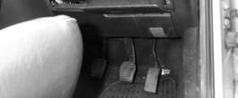


6 DIAGNOSTIC SOCKET LOCATIONS FIESTA MONDEO 2002 FOCUS PUMA FUSION/FIESTA SCORPIO GALAXY TRANSIT 2002 GALAXY2 TRANSIT UPTO VERSION: 2.9 JULY 2011 COPYRIGHT 2011


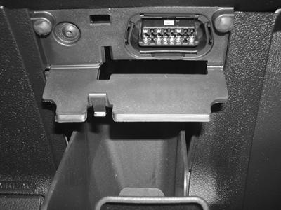

7 DIAGNOSTIC SOCKET LOCATIONS COUGAR TRANSIT 2007 on COURIER S MAX 2007 on COURIER GALAXY 2010 on TRANSIT CONNECT ESCORT/FIESTA 2 PIN 7 VERSION: 2.9 JULY 2011 COPYRIGHT 2011
8 GENERAL OPERATION INTRODUCTION - TIMED ACCESS The FORD PATS systems were introduced on Ford vehicles on 94.5 M.Y. vehicles, and was available from March There have been many variations on the original system fitted. This system has a separate PATS Amplifier, however on subsequent systems the PATS module was incorporated into the Engine Management ECU. SYSTEM OPERATION The PATS system is a PASSIVE Anti-theft system which requires no special procedures for the driver to arm or disarm the system. The system is operated by a transponder fitted within the ignition key s body, which communicates with the PATS module ignition transceiver mounted around the lock barrel. The easy method of identifying a PATS vehicle is if the key has a small imprint showing where the transponder is fitted. The code for the transponder is stored in memory within the PATS amplifier or the Engine Management ECU. The PATS system reads the code when the ignition key is turned from position 0 to position 1. If the correct code is received then the engine will start. When vehicles are fitted with Diesel Smart Modules or EPIC, the PATS code is stored in these systems as well, and requires clearing when new keys are programmed. KEY OPERATION - UP TO 98 ¼ MY Three keys are allocated to each vehicle, the first key which is inserted is known as the master and is usually identified by it s RED colour. The other keys that are used are known as slave keys and are usually BLACK with a RED insert. Up to 16 keys can be programmed into the PATS system. KEY OPERATION - 98¼ MY ONWARDS The newer systems are only supplied with 2 keys. Both keys are required to program further slave keys. Up to a maximum of 8 keys can be programmed to this PATS system. PATS LED INDICATOR The LED indicator is used for the PATS system and also other Anti-theft systems fitted to the Ford vehicle range. When the ignition is switched ON, the PATS LED will illuminate for 3 seconds while it performs a self-test, after which it extuingishes. When the PATS system is armed and immobilised the vehicle, the PATS LED will flash quickly. If there is a fault on the PATS system, and the engine can start, the PATS LED will illuminate for 60 seconds continuously, and then flash the PATS fault code 10 times. If the engine is unable to start and disabled by the PATS system, then the PATS LED will FLASH for 60 seconds and then flash the PATS fault code 10 times. PATS LED is mounted either in the front headlining or next to the heater controls/clock. PATS SYSTEM - PROBE ONLY The PATS system fitted to the Probe is unlike the other systems. The main difference is the system cannot be diagnosed with the FDS2000 or the AD PROGRAMMING SYSTEM. Additional keys and re-programming of new keys are performed in a different procedure as well. 8 VERSION: 2.9 JULY 2011 COPYRIGHT 2011
9 GENERAL OPERATION INTRODUCTION - CODED ACCESS The Ford coded access system was introduced in the year 2002, and the first vehicle that had this system was the FORD KA. The system replaces the TIMED ACCESS, which was first used in The new system replaces the TIMED ACCESS countdown timer with a security algorithm which will display an outcode when you try to program keys. This outcode needs converting and an incode is required. Advanced Diagnostics have developed a system which uses this incode and outcode system, however the way the system works means that it is not 100% accurate and some vehicles cannot be programmed until the codes have been checked. The system uses an internet system as described on the following pages, and requires web access when you are at the vehicle, Advanced Diagnostics forum access and a valid AD100, MVP, TCODE, Codeseeker or DM100 serial number and passcode to use the system. NEW FIESTA The new fiesta can be a difficult vehicle to program, as there are 2 systems TYPE 1 and TYPE 2. The problem is that it is difficult to know which is the correct one, and therefore because you can communicate with both, it means if you do not identify the correct system, then you have to try both types with the coded procedures. Here is a guide to identify the systems TYPE 1 Type 1 are generally up to 2004 model year. TYPE 2 When you try to ADD or CLEAR the system, the MAIN RELAY will click and the FUEL PUMP will run for a brief second, this indicates it is a TYPE 2 system. Also TYPE 2 systems tend to have CHROME BEZEL/EDGING on the instrument cluster. Type 2 are generally from MARCH 2005 onwards FORD CODED 2007 Ford have updated their coded system from 2007 for Transit, Mondeo, S Max and later Fiesta. The system operates on the same principle as the earlier coded vehicles ie it requires an Incode and Outcode via our website. The differences are: 1. The remote part of the key is programmed when the keys are programmed. 2. Once the keys have been erased, the new keys need to be programmed individually using the function. IMPORTANT: These keys are not cycled in at the end, please follow the on screen instructions. 9 VERSION: 2.9 JULY 2011 COPYRIGHT 2011
10 GENERAL OPERATION FORD SYSTEMS SYSTEM TIMED ACCESS CODED ACCESS MIN NO. OF KEYS IGNITION ON BEFORE CONNECTING TESTER (*) CLEAR TIME (Minutes) PATS 1 3 8:00 PATS 2 3 8:00 PATS 2 DIESEL 3 23:00 PATS 3 SCP 2 10:00 PATS 3 SCP DIESEL 2 10:00 PATS 3 SCP CODED 2 - PATS 3 CAN CODED 2 - PROXIMITY 2 - NON PROX CODED TRANSIT CODED FIESTA 2 - FALCON BEM 2 10:00 FALCON PCM 2 10:00 BA FALCON 2 10:00 BF FALCON 2 - (*) TURN IGNITION ON AND LET IMMOBILISER LED STOP FLASHING. THEN CONNECT TESTER 10 VERSION: 2.9 JULY 2011 COPYRIGHT 2011
11 PATS 1 & 2 (Petrol) + FORD + GM (USA) + GM / OPEL + HONDA / ACURA + HYUNDAI + INFINITI 93 > > 01 + AUS + EURO + USA + S. AMERICA : 2 CLEAR TIME: 8.00 THE FOLLOWING PROCEDURE SHOWS BY VEHICLE SELECTION. IF BY SYSTEM IS CHOSEN THEN THE SYSTEM TYPE WHERE KNOWN IS SHOWN IN THE APPLICATION PAGES PATS 1 THE TESTER WILL NOW CLEAR THE SYSTEM WHICH WILL TAKE APPROX 8 MINUTES. SWITCH THE IGNITION KEY TO THE ACCESSORY POSITION + BY VEHICLE + BY SYSTEM FAULT CODES > CLEAR PATS 1 KEY SWITCH IGN. ACCESSORY IGNITION STATUS: ON + C MAX COUGAR ESCAPE + ESCORT/ORION + EXPOLRER + FAIRLANE CLEAR PATS 1 KEY TIME REQUIRED 8:00 ****** BACK TO ABORT + PETROL + DIESEL KEYS PROGRAMED 2 CLEAR PATS 1 SYSTEM ALL KEYS CLEARED : 0 11 VERSION: 2.9 JULY 2011 COPYRIGHT 2011
12 PATS 1 & 2 (Petrol) PROGRAM KEYS MIN 3 KEYS REQUIRED FAULT CODES > The key in the ignition is now programmed as the master key. A minimum of 3 keys are required to finish the programming sequence. To program in the additional keys, insert each key and cycle the key in the ignition from OFF to ON and then back to OFF. Then remove. Repeat for second key. After 2 minutes try starting with both keys. 12 VERSION: 2.9 JULY 2011 COPYRIGHT 2011
13 PATS 1 & 2 (Diesel) + FORD + GM (USA) + GM / OPEL + HONDA / ACURA + HYUNDAI + INFINITI 93 > > 01 + AUS + EURO + USA + S. AMERICA CLEAR TIME: 8.00 THE FOLLOWING PROCEDURE SHOWS BY VEHICLE SELECTION. IF BY SYSTEM IS CHOSEN THEN THE SYSTEM TYPE WHERE KNOWN IS SHOWN IN THE APPLICATION PAGES PATS 2 DIESEL THE TESTER WILL NOW CLEAR THE SYSTEM WHICH WILL TAKE APPROX 8 MINUTES. FOLLOWED BY APPROX 15 MINS TO CLEAR THE DSM MODULE. + BY VEHICLE + BY SYSTEM FAULT CODES > CLEAR PATS 2 KEY TIME REQUIRED 8:00 ****** BACK TO ABORT + C MAX COUGAR ESCAPE + ESCORT/ORION + EXPOLRER + FAIRLANE CLEAR PATS 2 DSM TIME REQUIRED 15:00 ****** BACK TO ABORT + PETROL + DIESEL KEYS PROGRAMED 2 SWITCH IGNITION OFF 13 VERSION: 2.9 JULY 2011 COPYRIGHT 2011
14 PATS 1 & 2 (Diesel) CLEAR PATS 2 SYSTEM ALL KEYS CLEARED : 0 PROGRAM KEYS MIN 3 KEYS REQUIRED FAULT CODES > The key in the ignition is now programmed as the master key. A minimum of 3 keys are required to finish the programming sequence. To program in the additional keys, insert each key and cycle the key in the ignition from OFF to ON and then back to OFF. Then remove. Repeat for second key. After 2 minutes try starting with both keys. 14 VERSION: 2.9 JULY 2011 COPYRIGHT 2011
15 PATS GALAXY (Diesel) SOME FORD GALAXYS REQUIRE YOU TO TURN IGNITION ON AND LET IMMOBILISER LED STOP FLASHING. THEN CONNECT TESTER. A MINIMUM OF 2 KEYS IS REQUIRED. + PETROL + DIESEL CLEAR KEY - GALAXY MIN KEYS REQUIRED: 2 + FORD + GM (USA) + GM / OPEL + HONDA / ACURA + HYUNDAI + INFINITI > > > > THE TESTER WILL NOW CLEAR THE SYSTEM WHICH WILL TAKE APPROX 8 MINUTES. FOLLOWED BY APPROX 15 MINS TO CLEAR THE DSM MODULE. + AUS + EURO + USA + S. AMERICA CLEAR KEY - GALAXY TIME REQUIRED 8:00 ****** WAITING TO CLEAR BACK TO ABORT THE FOLLOWING PROCEDURE SHOWS BY VEHICLE SELECTION. IF BY SYSTEM IS CHOSEN THEN THE SYSTEM TYPE WHERE KNOWN IS SHOWN IN THE APPLICATION PAGES 7 MO953257AB V41 V V BC 2 3 K PLEASE ENTER THE TOTAL NUMBER OF KEYS YOU REQUIRE TO PROGRAM + BY VEHICLE + BY SYSTEM FAULT CODES > CLEAR KEY - GALAXY : 0 TOTAL KEYS REQD: FOCUS + GALAXY + FUSION + GRANADA / SCORPIO + KA + LTD PROGRAM KEYS PROGRAMMING KEYS TOTAL KEYS REQD: 2 15 VERSION: 2.9 JULY 2011 COPYRIGHT 2011
16 PATS GALAXY (Diesel) PLEASE PROGRAM ADDITIONAL KEYS The key in the ignition is now programmed. A minimum of 2 keys are required to finish the programming sequence. To program in the additional keys, insert each key and cycle the key in the ignition from OFF to ON and then back to OFF. Then remove. Repeat for second key. After 2 minutes try starting with all keys. 16 VERSION: 2.9 JULY 2011 COPYRIGHT 2011
17 PATS 3 (SCP) TURN IGNITION ON AND LET IMMOBILISER LED STOP FLASHING. THEN CONNECT TESTER. A MINIMUM OF 2 KEYS IS REQUIRED. 94 > 96 96/97 97/98 98 > > + FORD + GM (USA) + GM / OPEL + HONDA / ACURA + HYUNDAI + INFINITI MIN KEYS REQUIRED: 2 TIMED ACCESS CLEAR TIME 10:00 : 2 + AUS + EURO + USA + S. AMERICA PATS 3 SCP CLEAR PATS 3 KEY GAINING ACCESS TIME REQUIRED 10:00 ****** ACCESS STATUS IN PROGRESS BACK TO ABORT + MONDEO + PUMA + RANGER + S-MAX + TRANSIT CONNECT + TRANSIT FAULT CODES ACTUATORS > The tester will now start to clear the PATS system from memory. NOTE : If ACCESS STATUS IN PROGRESS is not displayed this indicates the incorrect system has been selected. + PETROL + DIESEL PROGRAM KEYS DISCONNECT TESTER FROM VEHICLE CYCLE KEYS TO PROGRAM + MANUAL + AUTOMATIC KEYS PROGRAMED 2 After clearing, cycle the key in the ignition from ON to OFF and then back to ON. Then remove. Repeat for second key. After 2 minutes try starting with both keys. 17 VERSION: 2.9 JULY 2011 COPYRIGHT 2011
18 PATS 3 (SCP) Check the anti-theft warning light for each key. It should turn on for 2 seconds and then go off with each key.. Rapid flashing means either the key is faulty or un-programmed. NOTES : 1. If an error is made, leave the ign on for 20 sec & insert both keys and turn ign ON. Then try starting again. 2. If the diagnostic session is called before other systems are allowed to settle, the counter will show 0.00 and access denied or coded access. FAULT CODES ACTUATORS > FINISHED Using the function is the same as CLEAR / ERASE except it only programs the key in the ignition. NOTES: 1. This function is not available on every vehicle eg Fleet vehicles 18 VERSION: 2.9 JULY 2011 COPYRIGHT 2011
19 PATS 3 SCP (CODED) TURN IGNITION ON AND LET IMMOBILISER LED STOP FLASHING THEN CONNECT TESTER. A MINIMUM OF 2 KEYS IS REQUIRED. MIN KEYS REQUIRED: 2 CODED ACCESS + FORD + GM (USA) + GM / OPEL + HONDA / ACURA + HYUNDAI + INFINITI PATS 3 SCP MIN KEYS REQUIRED: 2 CODED ACCESS : 2 + AUS + EURO + USA + S. AMERICA FAULT CODES ACTUATORS > ACCESS GRANTED + MONDEO + PUMA + RANGER + S-MAX + TRANSIT CONNECT + TRANSIT PROGRAM KEYS DISCONNECT TESTER FROM VEHICLE CYCLE KEYS TO PROGRAM + PETROL + DIESEL KEYS PROGRAMED 2 CYCLE A MIN OF 2 KEYS. 96 / / > > 19 VERSION: 2.9 JULY 2011 COPYRIGHT 2011
20 FAULT CODES ACTUATORS > PATS 3 SCP (CODED) MIN KEYS REQUIRED: 2 CODED ACCESS : 2 ACCESS GRANTED READING KEY : 2 BACK TO EXIT ENTER TO PROGRAM NEXT KEY THE KEY IN THE IGNITION GETS ADDED. IF MORE KEYS ARE REQUIRED THEN REPEAT PROCEDURE. 20 VERSION: 2.9 JULY 2011 COPYRIGHT 2011
21 PATS 3 CAN (CODED) + FORD + GM (USA) + GM / OPEL + HONDA / ACURA + HYUNDAI + INFINITI 05 FOCUS PATS 3 CAN (P.C.M) ACCESS GRANTED + AUS + EURO + USA + S. AMERICA FAULT CODES ACTUATORS > PROGRAM KEYS DISCONNECT TESTER FROM VEHICLE CYCLE KEYS TO PROGRAM + FOCUS + GALAXY + FUSION + GRANADA / SCORPIO + KA + LTD CYCLE A MIN OF 2 KEYS. + PETROL + DIESEL KEYS PROGRAMED 2 98 > > MIN KEYS REQUIRED: 2 CODED ACCESS 21 VERSION: 2.9 JULY 2011 COPYRIGHT 2011
22 2007 CODED TRANSIT REMOTE IS PROGRAMMED AT THE SAME TIME AS THE KEY. MIN 2 KEYS MUST BE PROGRAMMED PROCEDURE COMPLETE + FORD + GM (USA) + GM / OPEL + HONDA / ACURA + HYUNDAI + INFINITI PATS 3 CAN (P.C.M) IMPORTANT ONCE THE CORRECT CODE HAS BEEN ACCEPTED DO NOT DISCONNECT TESTER. PRESS ENTER AND SELECT ADD KEY FUNCTION TO NOW PROGRAM A KEY + AUS + EURO + USA + S. AMERICA > + MONDEO + PUMA + RANGER + S-MAX + TRANSIT CONNECT + TRANSIT : 1 BACK TO EXIT ENTER TO PROGRAM NEXT KEY + PETROL + DIESEL + DURA-TORQUE + EPIC KEYS PROGRAMED 2 REMOVE KEY FROM IGNITION AND INSERT NEXT KEY TO BE PROGRAMMED. 94 / / / > > 22 VERSION: 2.9 JULY 2011 COPYRIGHT 2011
23 2007 CODED TRANSIT REMOVE KEY FROM IGN INSERT NEXT KEY : 2 BACK TO EXIT ENTER TO PROGRAM NEXT KEY REMOVE KEY FROM IGNITION AND INSERT NEXT KEY TO BE PROGRAMMED. OR ENTER TO FINISH PROCEDURE COMPLETE FINISHED 23 VERSION: 2.9 JULY 2011 COPYRIGHT 2011
24 2007 CODED FIESTA REMOTE IS PROGRAMMED AT THE SAME TIME AS THE KEY. MIN 2 KEYS MUST BE PROGRAMMED CLEAR KEYS WARNING ALL KEYS WILL BE CLEARED CONTINUE + FORD + GM (USA) + GM / OPEL + HONDA / ACURA + HYUNDAI + INFINITI PATS 3 CAN (P.C.M) KEYS PROGRAMED 2 KEY STATUS: PROG + AUS + EURO + USA + S. AMERICA > CLEAR KEYS SUCCESS + FAIRLANE + FAIRMONT + FIESTA/COURIER + FOCUS + GALAXY + FUSION CLEAR KEYS PROGRAM KEYS IMPORTANT ONCE THE CORRECT CODE HAS BEEN ACCEPTED DO NOT DISCONNECT TESTER. PRESS ENTER AND SELECT PROGRAM KEYS FUNCTION TO PROGRAM KEY (S) + PETROL + DIESEL KEYS PROGRAMED 2 KEY STATUS: PROG CLEAR KEYS PROGRAM KEYS 95 > > > > > CLEAR KEYS PROGRAM KEYS KEYS PROGRAMED 0 KEY STATUS: PROG 24 VERSION: 2.9 JULY 2011 COPYRIGHT 2011
25 2007 CODED FIESTA IMMOBILISER WARNING LIGHT WILL FLASH TO INDICATE AN UNPROGRAMMED KEY IS IN THE IGNITION. CYCLE THE IGNITION WITH THE KEY. CLEAR KEYS PROGRAM KEYS CLEAR KEYS PROGRAM KEYS KEYS PROGRAMED 0 KEY STATUS: UNPROGRAMMED IMPORTANT IF YOU WANT TO PROGRAM MORE KEYS DO NOT DISCONNECT TESTER. PRESS ENTER AND SELECT PROGRAM KEYS FUNCTION TO PROGRAM ADDITIONAL KEY (S) REPEAT FOR ALL KEYS ADDITIONAL KEYS FINISHED IGNIITION ON ADDITIONAL KEYS INSERT KEY TO PROGRAM IGNITION ON ADDITIONAL KEYS SUCCESS CYCLE IGNITION TO PROGRAM 25 VERSION: 2.9 JULY 2011 COPYRIGHT 2011
26 CODED PROXIMITY REMOTE IS PROGRAMMED AT THE SAME TIME AS THE PROXIMITY FOB. MIN 2 KEYS MUST BE PROGRAMMED + NON PROXIMITY + PROXIMITY KEYS PROGRAMED: 2 PROG KEYS IN CABIN: 0 + FORD + GM (USA) + GM / OPEL + HONDA / ACURA + HYUNDAI + INFINITI ADDING KEYS ENSURE KEY IS IN CABIN WHEN SWITCHING IGNITION ON. LOST KEYS PRESS THE IGNITION BUTTON ONCE ONLY. THIS WILL ALLOW THE TESTER TO COMMUNICATE. NO VISIBLE INDICATION SHOWS THE IGNITION IS ON. CLEAR / PROGRAM KEYS ADDITIONAL KEYS CLEAR KEYS + AUS WARNING + EURO ALL KEYS WILL BE + USA CLEARED + S. AMERICA CONTINUE + KA + LTD PATS PROX CAN KEYS PROGRAMED: 2 + MAVERICK + MONDEO PROG KEYS IN CABIN: 0 + PUMA + RANGER + PETROL + DIESEL FAULT CODES > ADDING KEYS ENSURE KEY IS IN CABIN WHEN SWITCHING IGNITION OFF. LOST KEYS PRESS THE IGNITION BUTTON ONCE ONLY. NO VISIBLE INDICATION SHOWS THE IGNITION IS OFF. 96 > > > > CLEAR / PROGRAM KEYS ADDITIONAL KEYS CLEAR KEYS IGNITION OFF 26 VERSION: 2.9 JULY 2011 COPYRIGHT 2011
27 CODED PROXIMITY PROGRAM PROX FOB PROGRAM PROX FOB ACCESS GRANTED PRESS UNLOCK FOR 15 SEC WHEN PROMPTED PRESS UNLOCK FOR 15 SEC ON PROX FOB 2 CLEAR KEYS ACCESS GRANTED PROGRAM PROX FOB PROX FOB 1 SUCCESS THE PROX FOB MUST BE INSIDE THE VEHICLE CABIN WHILST BEING PRESSED. CLEAR KEYS SUCCESS REMOVE BLANKING INSERT FROM KEY SLOT ON THE STEERING COLUMN. PROGRAM PROX FOB PRESS UNLOCK FOR 15 SEC PROGRAM KEYS 2 KEYS REQUIRED PROGRAM TRANSPONDER PLACE PROX FOB 1 IN EMERGENCY KEY SLOT PROGRAM PROX FOB PROX FOB 2 SUCCESS PROGRAM PROX FOB WHEN PROMPTED PRESS UNLOCK FOR 15 SEC ON PROX FOB 1 THE PROX FOB MUST BE INSIDE THE VEHICLE CABIN WHILST BEING PRESSED. PROGRAM TRANSPONDER TRANSPONDER 1 SUCCESS PROGRAM TRANSPONDER REMOVE PROX FOB FROM EMERGENCY KEY SLOT PROGRAM TRANSPONDER PLACE PROX FOB 2 IN EMERGENCY KEY SLOT PROGRAM TRANSPONDER TRANSPONDER 2 SUCCESS 27 VERSION: 2.9 JULY 2011 COPYRIGHT 2011
28 CODED PROXIMITY PROGRAM TRANSPONDER REMOVE PROX FOB FROM EMERGENCY KEY SLOT PROGRAM KEYS 2 DO YOU WANT TO PROG ADDITIONAL KEYS IF ANOTHER KEY REQUIRES PROGRAMMING THE PROCESS WILL BE REPEATED. FINISHED 28 VERSION: 2.9 JULY 2011 COPYRIGHT 2011
29 2007 CODED - NON PROX REMOTE IS PROGRAMMED AT THE SAME TIME AS THE PROXIMITY FOB. MIN 2 KEYS MUST BE PROGRAMMED + NON PROXIMITY + PROXIMITY + FORD + GM (USA) + GM / OPEL + HONDA / ACURA + HYUNDAI + INFINITI PROCEDURE COMPLETE + AUS + EURO + USA + S. AMERICA PATS NON-PROX CAN IMPORTANT ONCE THE CORRECT CODE HAS BEEN ACCEPTED DO NOT DISCONNECT TESTER. PRESS ENTER AND SELECT ADD KEY FUNCTION TO NOW PROGRAM A KEY + MONDEO + PUMA + RANGER + S-MAX + TRANSIT CONNECT + TRANSIT > + PETROL + DIESEL : 1 BACK TO EXIT ENTER TO PROGRAM NEXT KEY 96 > > > > KEYS PROGRAMED 2 REMOVE KEY FROM IGNITION AND INSERT NEXT KEY TO BE PROGRAMMED. 29 VERSION: 2.9 JULY 2011 COPYRIGHT 2011
30 2007 CODED - NON PROX REMOVE KEY FROM IGN INSERT NEXT KEY : 2 BACK TO EXIT ENTER TO PROGRAM NEXT KEY REMOVE KEY FROM IGNITION AND INSERT NEXT KEY TO BE PROGRAMMED. OR ENTER TO FINISH PROCEDURE COMPLETE FINISHED 30 VERSION: 2.9 JULY 2011 COPYRIGHT 2011
31 FALCON - BEM + FORD + GM (USA) + GM / OPEL + HONDA / ACURA + HYUNDAI + INFINITI FAULT CODES > Once all keys have been programmed press ENTER. + AUS + EURO + USA + S. AMERICA FINISHED + AU FALCON + BA FALCON + BF FALCON SWITCH IGNITION OFF + BEM + PCM WAITING TO CLEAR BACK TO ABORT CODE CLEARED SWITCH IGNITION OFF BACK TO ABORT FALCON BEM PATS PROGRAM KEYS SWITCH IGN. ON WITHIN 5 SEC REMOVE KEYS FROM IGN. INSERT NEXT KEY REPEAT FOR ALL KEYS 31 VERSION: 2.9 JULY 2011 COPYRIGHT 2011
32 FALCON - PCM + FORD + GM (USA) + GM / OPEL + HONDA / ACURA + HYUNDAI + INFINITI + AUS + EURO + USA + S. AMERICA FAULT CODES > PARAMETER RESET The key in the ignition is now Programmed. A minimum of 2 keys are required to finish the programming sequence. To program in the additional keys, insert each key and cycle the key in the ignition from OFF to ON and then back to OFF. Then remove. Repeat for second key. After 2 minutes try starting with both keys. + AU FALCON + BA FALCON + BF FALCON PROGRAM KEYS TIMED ACCESS CLEAR TIME 10:00 FINISHED + BEM + PCM GAINING ACCESS TIME REQUIRED 10:00 ****** BACK TO ABORT ACCESS GRANTED BACK TO ABORT FALCON PCM PATS PROGRAM KEYS PROCEDURE COMPLETE SWITCH IGNITION OFF 32 VERSION: 2.9 JULY 2011 COPYRIGHT 2011
33 BA FALCON / SX TERRITORY TURN IGNITION ON AND LEAVE FOR 30 SECONDS BEFORE CONNECTING THE TESTER. A MINIMUM OF 2 KEYS IS REQUIRED. > Failure to Press Enter before cycling keys will result in a failed key programming session and MVP Token loss where applicable + FORD + GM (USA) + GM / OPEL + HONDA / ACURA + HYUNDAI + INFINITI CLEAR PATS SYSTEM WHEN PROMPTED WITHIN 10 SEC TURN IGN ON WITH 1ST KEY THEN WITHIN 5 SECONDS INSERT 2ND KEY AND TURN IGNITION ON + AUS + EURO + USA + S. AMERICA MIN 2 KEYS REQUIRED CONTINUE PRESS BACK WHEN FINISHED YES = ENTER NO = BACK + AU FALCON + BA FALCON + BF FALCON SWITCH IGNITION OFF TIMED ACCESS GAINING ACCESS TIME REQUIRED 10:00 ****** ACCESS STATUS IN PROGRESS BACK TO ABORT DO NOT REMOVE KEY ENSURE ALL DOORS ARE CLOSED ACCESS GRANTED FALCON PATS 3 CAN WARNING NOTE On the following screen when the ENTER key is pressed the door locks will cycle which is the prompt to cycle the keys through the ignition. When 10 min. has passed screen will return to diagnostics menu. Switch ign off. Door locks will lock Using same key switch ignition ON, then OFF. Start vehicle. 33 VERSION: 2.9 JULY 2011 COPYRIGHT 2011
34 BF FALCON / SY TERRITORY TURN IGNITION ON AND LEAVE FOR 30 SECONDS BEFORE CONNECTING THE TESTER. > A MINIMUM OF 2 KEYS IS REQUIRED. + FORD + GM (USA) + GM / OPEL + HONDA / ACURA + HYUNDAI + INFINITI CLEAR/ ERASE PATS PARAMETER RESET + AUS + EURO + USA + S. AMERICA MIN 2 KEYS REQUIRED CONTINUE YES = ENTER NO = BACK + AU FALCON + BA FALCON + BF FALCON ACCESS GRANTED SWITCH IGN OFF DO NOT REMOVE KEY ENSURE ALL DOORS ARE CLOSED BF FALCON PATS 3 CAN 34 VERSION: 2.9 JULY 2011 COPYRIGHT 2011
35 BF FALCON / SY TERRITORY PARAMETER RESET When ENTER pressed door locks will lock TO COMPLETE THE PROGRAMMING PROCEDURE PLEASE DISCONNECT THE TESTER AND RE-START. THEN SELECT PARAMETER RESET SWITCH IGNITION OFF WHEN PROMPTED WITHIN 10 SEC TURN IGN ON WITH 1ST KEY THEN WITHIN 5 SECONDS INSERT 2ND KEY AND TURN IGNITION ON CLEAR/ ERASE PATS PARAMETER RESET DISCONNECT TESTER PRESS BACK WHEN FINISHED ACCESS GRANTED SWITCH IGNITION OFF LOCKS SHOULD CYCLE IF PARAMETER RESET SUCCESSFUL SWITCH IGNITION OFF DISCONNECT TESTER AND PERFORM PARAMETER RESET 35 VERSION: 2.9 JULY 2011 COPYRIGHT 2011
36 FG FALCON + FORD + GM (USA) + GM / OPEL + HONDA / ACURA + HYUNDAI + INFINITI CLEAR ERASE PATS WHEN PROMPTED TURN IGN ON WITH 1ST KEY WITHIN 10 SECS THEN TURN IGN ON WITH 2ND KEY WITHIN 5 SECS + AUS + EURO + USA + S.AMERICA CLEAR KEYS CLEAR ERASE PATS : 00 TIME : 09 + FAIRLANE + AU FALCON + BA FALCON + BF FALCON + FG FALCON : 02 CLEAR ERASE PATS : 01 TIME : 07 + BEM + ICM + PCM CLEAR KEYS CLEAR ERASE PATS REMOVE KEY FROM IGN THEN INSERT NEXT KEY SWITCH IGN ON : 02 TIME : 07 CLEAR ERASE PATS 2 KEYS REQUIRED DO YOU WANT TO SWITCH IGNITION OFF CONTINUE CLEAR ERASE PATS TURN IGNITION OFF FG FALCON BEM DO NOT REMOVE KEY ENSURE ALL DOORS ARE CLOSED 36 VERSION: 2.9 JULY 2011 COPYRIGHT 2011
37 FG FALCON PARAMETER RESET ICM + BEM + ICM + PCM CLEAR ERASE PATS DISCONNECT TESTER RECONNECT AND PERFORM PARAMETER RESET ON ICM PARAMETER RESET ICM INCODE OUTCODE + BEM + ICM + PCM ACCESS GRANTED FG FALCON VIN : 6FPAAAJGSWA PARAMETER RESET ICM SWITCH IGNITION OFF PARAMETER RESET ICM FG FALCON IC PARAMETER RESET PCM CLEAR ERASE PATS DISCONNECT AD100PRO INSERT DONGLE A PERFORM PARAMETER RESET ON PCM 37 VERSION: 2.9 JULY 2011 COPYRIGHT 2011
38 FG FALCON PARAMETER RESET PCM PARAMETER RESET PCM INCODE OUTCODE PLEASE WAIT * * * * * * * PARAMETER RESET ICM ACCESS GRANTED SWITCH IGNITION OFF PARAMETER RESET PCM PARAMETER RESET PCM PLEASE WAIT PLEASE WAIT * * * * * * * * * * * * * * PARAMETER RESET ICM PARAMETER RESET ICM SWITCH IGNITION OFF PARAMETER RESET PCM PARAMETER RESET PCM PLEASE WAIT DISCONNECT AD100PRO PROCEDURE COMPLETE * * * * * * * PARAMETER RESET ICM 38 VERSION: 2.9 JULY 2011 COPYRIGHT 2011
39 VIN CHECKER The Ford VIN checker is used to determin the production date of the vehicle. PRODUCTION DATE + FORD + GM (USA) + GM / OPEL + HONDA / ACURA + HYUNDAI + INFINITI JUL 98 + AUS + EURO + USA + S. AMERICA FORD CALCULATOR CHECK ANOTHER VIN YES = ENTER NO = BACK S MAX TRANSIT CONNECT TRANSIT WINDSTAR + FORD BY SYSTEM + FORD VIN CHECK FORD CALCULATOR ENTER LAST 7 DIGITS OF VIN NUMBER _ FORD CALCULATOR WM VERSION: 2.9 JULY 2011 COPYRIGHT 2011
40 TIPS AND HINTS GENERAL If communication is made with the vehicle, and then no communication is experienced later or the communication is random, check battery voltage and ensure it is at least 12.2 volts., particularly important on SCP, and all Transits A new function has been introduced on the WDS which enables the dealer to disable the additional key function. This is mainly used on fleet vehicles and hire companies to stop unauthorized key s being added. If a system will not accept additional keys, it may be because this has been enabled. Fleet mode (unable to add a key) is disabled by clearing the PATS and DSM (diesel only) and reprogramming all keys. When programming SCP systems, turn IGN ON before connecting TESTER or ADC110B to Diagnostic socket, then wait for dashboard lights to settle, connect TESTER - otherwise a timed access system may display access denied. Intermittent start with fault code 12- replace faulty aerial pick up. If an incorrect key is used to try and start the engine, the correct key must be inserted and left in the IGN position for at least 20 seconds, then switched OFF then back ON before the vehicle starts. Fault Code 0 is an ECU trouble code, if this is set and cannot be cleared, then there is a problem with the ECU. Normally the only way to fix this is to return the ECU for testing or replace it. Fault Code 1000 is an ECU trouble code. This code can be set automatically if the vehicle has not been driven. The code refers to the OBD drive cycle. In some instances it is not possible to program new keys if this code is set. Please follow the following instructions if the code cannot be cleared or the keys cannot be programmed. The OBD drive cycle code P1000 is the monitor code which monitors a number of the OBD parameters. This code can be cleared by driving the vehicle or running the engine for around 5 minutes at a steady RPM and acceleration cycles. The smoother the driving condition the quicker the code will be cleared. If no keys are available, then the ECU can be disconnected for minutes, which will also reset the system. SELF DIAGNOSIS The PATS system has it s own self diagnosis test procedure which flashes codes. The PATS LED will flash quickly for 1 minute, and then start flashing the fault code as follows:- Example Flash code for Fault Code 31 A = 3 Flashes B = 1 Flash C = Three seconds delay D = Repeat of code for 10 times A B C D Code 11 Transceiver not connected Code 12 Transceiver Code 13 No key data received Code 14 Part of the transponder code received Code 15 Wrong transponder key Code 21 Less than the minimum keys required programmed Code 22 Failed diesel pump control unit identification Code 23 The response code between pump control unit & powertrain Code 31 DSM Communication Code 32 DSM Communication Code 34 DSM Communication LED = Always ON or OFF - Check the fuse 15 (5 amp) NOTE : If there are no fault codes, DO NOT clear fault codes as this can cause fault 1000 to be enabled. Ford Escort, no communication with TESTER, switched Ignition OFF and ON very quickly, and communication gained. Conclusion was bad connection on ignition switch. DO NOT insert a blue chip transponder key into a red key system. 40 VERSION: 2.9 JULY 2011 COPYRIGHT 2011
41 TIPS AND HINTS < 98 ¼ MY NOTE a. Clear ALL Fault codes before programming. b. The Immobiliser receiver does not need reprogramming when replaced. c. Up to 16 keys can be programmed into the PATS system. A new master key can only be programmed using the FDS2000 or the AD PROGRAMMING systems. Further slaves can be added without any specialist equipment as follows :- 1. Insert master key, and turn to Position 2. PATS LED should illuminate. 2. Switch ignition from position 2 to position 0, and remove key. PATS LED will illuminate for 2 seconds. PATS system is now in programming mode for 10 seconds. 3. Insert the new slave key, and turn from Position 0 to Position 2. PATS LED will flash once if successful. 4. Repeat for all new slave keys. > 98 ¼ MY > NOTE a. Clear ALL Fault codes before programming. b. Up to 8 keys can be programmed into the PATS system. c. If programming is unsuccessful, the PATS LED will flash when the key is inserted. d. Newer systems are only supplied with 2 keys. Both keys are required to program further slave keys. e. Master keys can only be programmed using the 2 PATS keys (A and B) with the FDS2000 or the AD PROGRAMMING SYSTEM system. f. In some cases the vehicle doors must be closed to perform the re-programming sequence. Further slaves can be added without any specialist equipment as follows :- 1. Insert key A, and turn to Position Turn back to Position 0, and remove key A. 3. Insert key B, and turn to Position Turn back to Position 0, and remove key B. 5. Insert the new slave key and turn to Position Remove new key. Key is now programmed. 7. Procedure can be repeated after 20 seconds, for up to 8 slave keys. GALAXY MANUAL PROGRAMMING PROCEDURES DO NOT WORK ON ANY FORD GALAXY VEHICLES. PROBE PROGRAMMING NEW/ADDITIONAL KEYS (2 or more keys available) 1. Using one of the existing keys (This becomes KEY 1), insert into ignition switch. NOTE : When requested to turn the key ON or OFF, the time should not be less than 1 Second or more than 2 Seconds between operations. Unless stated otherwise. 2. Turn the Key to IGNITION ON and then OFF five times, stopping at the OFF position. NOTE : PATS LED Should remain ON with the key in the OFF position. 3. Turn the IGNITION ON using KEY 1., within 15 seconds of step Turn the IGNITION OFF and remove KEY Insert KEY 2 within 60 seconds of PATS LED illuminating. 6. Turn ign ON and start engine with KEY 2. PATS LED will extinguish after 1-2 sec and engine remain running if key is accepted. 7. Turn IGNITION OFF and remove KEY Insert KEY 3 within 15 seconds of removing KEY Turn IGNITION ON and start engine with KEY 3. PATS LED will extinguish after 1-2 seconds and engine remain running if key is accepted. 10. Turn IGNITION OFF and remove KEY 3. Repeat as necessary for additional keys. PROGRAMMING NEW/ADDITIONAL KEYS (No keys available) Programming new key(s) when no keys are available can only be completed by a FORD dealer. 41 VERSION: 2.9 JULY 2011 COPYRIGHT 2011
42 TIPS AND HINTS CLEARING/PROGRAMMING PATS 1 & 2 SYSTEM (PETROL) 1. If WAITING TO CLEAR is not displayed this indicates the incorrect system has been selected. 2. If successful the tester will display all keys cleared and how many keys are programmed. CLEARING PATS SYSTEM (FALCON) 1. Minimum 2 keys required. 2. Ensure all vehicle doors remain closed at all times. FUNCTION - CERTIAN VEHICLES 1. On some vehicles a function is available to add a key without deleting the old keys. This takes the normal 10 minutes security access time. 2. If the procedure is not followed then a further security access time of 10 minutes will be required. 3. Some vehicles, especially fleets and hire companies have this feature disabled, and the normal clear down procedure will be required. MANUAL (TEXAS 4D CARBON) 1. The MANUAL KEY REGISTRATION is NOT enabled on any vehicles that use the TEXAS 4D Carbon Transponders. FORD GALAXY TRANSPONDERS 1. The Ford GALAXY uses the following types of transponders id 33 Transponder id 42 Transponder id 44 Transponder id 63 Transponder 42 VERSION: 2.9 JULY 2011 COPYRIGHT 2011
43 TIPS AND HINTS RANGER PROCEDURES General Procedures 1.NOTE: When an error occurs during the reprogram procedures, except when both the immobilizer unit and PCM are replaced, repeat the procedure from Step 1. If you still cannot reprogram, confirm how many keys can start the engine. Then, perform the key replacement or additional reprogram procedure according to the val id key number. NOTE: To make a copy of the key or replace the immobilizer system component parts (the key(s), steering lock, immobilizer unit, and/or PCM), the customer should bring all keys to the dealer. This is because the previously programmed key IDs are erased when reprogramming the key IDs into the immobilizer unit and PCM. NOTE: If the customer has only one valid key when replacing the immobilizer system component parts, the dealer should contact a distributor to obtain the code word. NOTE: To replace the immobilizer unit or PCM, there should be at least one valid key. Otherwise, both the immobilizer unit and PCM should be replaced. NOTE: The immobilizer unit and PCM cannot be changed from one car to another. If an immobilizer unit or PCM is replaced with one from another car, the engine will not start. Reprogramming of the IDs and code word of an immobilizer unit that has already been programmed is not possible. NOTE: The immobilizer unit and PCM should not be newly replaced as a trial during troubleshooting. If this is done, the ID and code word will be programmed into the new unit and it cannot be used for other cars even if you find that the old unit was normal. NOTE: The immobilizer system cannot be deactivated. NOTE: Confirm that all keys registered can start the engine after the reprogram procedure. When confirming, wait for more than 5 seconds before inserting the next key. NOTE: When the customer does not need to register more than two keys, the following procedures can be stopped after registering two keys. NOTE: If the key cannot be registered in spite of the fact that the immobilizer system operates normally, there may be a malfunction with the key reminder switch or wiring harness. NOTE: If no specific time interval is given, each step should be performed within 30 seconds of the previous step. NOTE: If programming keys, the driver door must be open Key Replacement or Addition when the customer has two or more valid keys 1. NOTE: Key Replacement or Addition When the customer has two or more valid keys 2. Cut new transponder-equipped key(s). 3. Insert key 1 into the steering lock and hold for 1 second or more. 4. Remove and insert key 1 five times at no more than 1-second intervals. 5. After the final key insertion, verify that the security light flashes. 6. Remove the key from the steering lock and verify that the security light goes off. 7. Insert key 2 into the steering lock and turn the key to the ON position. 8. Verify that the security light illuminates for 1 2 seconds. 9. After verifying that the security light goes off, turn the key to the LOCK position and remove from the steering lock. 10. Insert key 3 into the steering lock and turn the key to the ON position. 11. Verify that the security light illuminates for 1 2 seconds. 12. After verifying that the security light goes off, turn the key to the LOCK position. 13. If there are 4 8 keys (valid and/or new keys), repeat Step 5 with each key. 14. Wait for 30 seconds. 15. After reprogramming, clear DTCs stored in the PCM. 43 VERSION: 2.9 JULY 2011 COPYRIGHT 2011
44 TIPS AND HINTS RANGER PROCEDURES Key Replacement or Addition when the customer has only one or no valid key (code word is required) 1. NOTE: If no specific time interval is given, each step should be performed within 30 seconds of the previous step. 2. Remove and insert key 1 five times at no more than 1-second intervals. 3. After the final key insertion, verify that the security light flashes. (300 ms ON 300 ms OFF) 4. Wait for 5 minutes until the security light flashes at 1.2-second intervals. 5. Input the code word. For additional information, refer tocode Word Input Procedure in this procedure. 6. After verifying that the security light has switched from flashing to straight illumination, turn the key to the ON position. 7. After verifying that the security light goes off, turn the key to the LOCK position and remove from the steering lock. 8. Insert key 2 into the steering lock and turn the key to the ON position. 9. Verify that the security light illuminates for 1 2 seconds. 10. After verifying that the security light goes off, turn the key to the LOCK position and remove from the steering lock. 11. Insert key 3 into the steering lock and turn the key to the ON position. 12. Verify that the security light illuminates for 1 2 seconds. 13. After verifying that the security light goes off, turn the key to the LOCK position. 14. If there are 4 8 keys (valid and/or new keys), repeat Step 5 with each key. 15. Wait for 30 seconds. 16. After reprogramming, clear DTCs stored in the PCM. 44 VERSION: 2.9 JULY 2011 COPYRIGHT 2011
45 REMOTE PROGRAMMING Fiesta 96> & Escort 98> (Radio 3 Button) Procedure 1. Insert Key and turn to II, then Turn Key from II to I and back to II four times within 3 seconds 2. The PATS LED should light. Turn Key to Position Press the Unlock button and keep it pressed until the PATS LED flashes 4 times. 4. Add additional fobs the same way. Turn to II and back to 0 to end. Focus (Radio 3 Button) Procedure 1. Switch Ignition On/Off (II/0) 4 times within 6 seconds until a sound is made. 2. Press any button on Remote until a sound is made. 3. To program additional Remotes, repeat after 2 seconds after the sound. 4. Turn Ignition On/Off to exit. 5. A maximum of 4 remotes can be programmed. Mondeo 96> Scorpio > 98 (Radio 2 Button) Procedure 1. Turn Ignition to II, then turn ignition from II to I and back 4 times within 3 seconds. 2. The PATS LED on dash should light. 3. Turn Ign to 0. Then press Unlock button and keep pressed until PATS LED flashes 4 times (new fob first, then old) 4. Turn Ignition to II, then back to 0 to end. Transit (2000.5MY) Procedure 1. Close all the doors. 2. Turn Ignition key from position 0 to II eight times within 10 seconds. 3. Make sure the vehicle locks and unlocks the doors. 4. Press the remote transmitter button within 20 seconds., and make sure the vehicle locks and unlocks all the doors. 5. Up to 20 seconds is allowed to programme the next remote transmitter. 6. To programme additional remote transmitters, repeat steps 4 and Turn the ignition key to position 0 to exit the programming mode. Note : Maximum 4 remote transmitters may be programmed. Note :. Ensure the vehicle battery is fully charged and the anti-theft alarm system is not armed or triggered. Note : If programming ends with no new remote transmitters, the originals are retained. Note : The anti-theft alarm and double locking module will exit programming mode automatically if four new remote transmitters have been programmed or if no new remote transmitters programmed within the 20 second programming mode. Fiesta 96, Puma (Infrared 2 Button) Procedure 1. Turn Ignition switch to Position I and back to 0 as soon as the PATS LED in the clock lights (The system is now ready for programming, to a maximum time limit of 30 seconds) 2. Remove Key from Ignition, hold the FOB towards the Interior Light, and press and hold the Single Arrow. Wait until the light on the Key flashes, then press the Double Arrow 3 times., release the Single Button 3. Both LEDs (Key & Clock) should flash to acknowledge programming is successful 4. To exit learn Mode, turn Ignition to II and then 0 5. A Maximum of 4 Remotes are possible 45 VERSION: 2.9 JULY 2011 COPYRIGHT 2011
46 REMOTE PROGRAMMING Mondeo 93> Mondeo 96> (Infrared 2 Button) Procedure 1. Unlock Vehicle, and turn ignition to position Wait until the PATS LED illuminates (app 10 seconds) 3. Switch Ignition to 0 within 5 seconds LED will remain on 4. Point the Remote at one of the front Receivers 5. Press a button and keep pressed within 20 seconds of step 3 6. When the LED on the Key lights press the other button 3-5 times 7. Release both buttons while still aiming at the receiver 8. If successful, both LED s will flash 5 times 9. Repeat 5 9 for additional transmitters (within 30 seconds) 10.When completed, Turn Ignition to II then 0 to store the Keys Mondeo 98½> Scorpio 95> (Radio 3 Button) Procedure 1. Turn Ignition 4 times from 0 to I, ending at position I. A tone should sound. 2. Press the Remote Unlock button another tone should sound. 3. Additional Remotes can be added by repeating Step 2, within ten seconds of each remote. 4. To exit turn Ignition to 0 another audible sound should be made. Cougar (Radio 3 Button) Procedure 1. Turn Ignition On (II) and Off (0) 4 times within 6 seconds 2. With the Ignition at 0 the PATS LED should light continuously. 3. Press any button on the Radio Remote within 10 seconds 4. The LED should flash to acknowledge 5. Further Remotes (max. 4) can be added by pressing any button. 6. Program mode will end if Ignition turned on, or no new Remote Detected within 10 seconds NOTE : The first Cougars were 3 seconds instead of 6, and 20 seconds instead of 10. Scorpio 95> (Radio 3 Button) 1. Turn Ignition 4 times from 0 to I, ending at position I. An audible tone should be heard. 2. Press the Remote Unlock button there should be another audible tone 3. If more than one Remote then Step 2 should be repeated for each remote in turn, within ten seconds of each other. 4. To End turn Ignition to 0 there should be another audible tone. Galaxy (Radio 2 button) 1. Make sure all doors and windows are closed. 2. Turn the key in the drivers door lock, 3 times to the unlock position for at least half a second and within a total of 5 seconds. 3. The system should now enter programming mode, this is shown by the LED illuminating continuously for the next 15 secs- during which the key should be programmed as follows. 4. Press one of the buttons on the key and whilst holding it pressed, simultaneously press the other button 3 times. 5. Release both buttons. 6. The key should now flash 5 times and the LED in the door should also flash, six times. 46 VERSION: 2.9 JULY 2011 COPYRIGHT 2011
47 REMOTE PROGRAMMING Additional Information A maximum of four keyless entry remote transmitters can be programmed to the central security module (CSM). Programming must be done at the same time for all the transmitters. Note: To enter programming mode, make sure that the vehicle battery is fully charged and the anti-theft system is not armed or triggered (if equipped). 1. Close all doors and fasten the safety belts to make sure conflicting chimes do not sound during programming. 2. Turn the ignition switch from position I to position II at least four times in six seconds. 3. Turn the ignition switch to position I. 4. The CSM is now in the learning mode. 5. Press and hold one of the buttons on the remote transmitter until a chime sounds. This indicates a new transmitter code has successfully received. 6. After each successful programming is completed, another 10 second learning mode is automatically entered, up to a maximum of four times. 7. To program additional transmitters, repeat from step The system will leave the learning mode after the ignition switch is turned to position III, or if no new transmitter is programmed during the 10 seconds, or if four remote transmitters have been programmed. Note: An incorrect programming procedure does not effect the stored codes. 9. After successful programming, only the new programmed transmitters will be accepted. 10. Test all the programmed transmitters, by activating and deactivating the locking/unlocking functions. Focus Built from Onwards Note: The ignition must be turned off before attempting to reprogram the key fob. 1. The unlocking mode can be changed by pressing the locking and unlocking buttons on the remote transmitter simultaneously for a minimum of four seconds. 2. The change is indicated by the turn signal lamps flashing twice. 3. The mode can be carried out as often as required by repeating step 11. Mondeo 2001 onwards Note: The ignition must be turned off before attempting to reprogram the key fob. 1. The unlocking mode can be changed by pressing the locking and unlocking buttons on the remote transmitter simultaneously for a minimum of four seconds. 2. The change is indicated by the turn signal lamps flashing twice. 3. The mode can be carried out as often as required by repeating step 14. Programming transmitters. 1. Insert the ignition key and turn it from position II to position 0 and back four times within three seconds. 2. Remove the ignition key. The module remains in learning mode for 20 seconds and the anti-theft warning system light stays on continuously. 3. Press one of the transmitter buttons. The signal is learned by the module and indicated by a flashing anti-theft warning system light. If necessary, repeat the procedure for other transmitters after two seconds. 4. Wait until the module programming is complete, or switch the ignition to ON. Notes: A maximum of four keyless entry remote transmitters can be programmed to the central security module. Programming must be done at the same time for all the transmitters. To enter programming mode, make sure that the vehicle battery is fully charged and the anti-theft system is not armed or triggered (if equipped). Close all doors and fasten the safety belts to make sure conflicting chimes do not sound during programming. 5. Turn the ignition switch from the OFF position to the ON position four times within three seconds to enter the learning mode. Turn the ignition switch from the OFF position. The central security module will remain in the learning mode for 20 seconds indicated by the LED in the instrument panel being illuminated continuously. 6. Press any button on the remote transmitter being programmed. When the signal from the remote transmitter is accepted by the central security module, the LED will flash. 7. To program additional transmitters, repeat from step 6, with a two second delay after the LED flashes. 8. To exit the learning mode, turn the ignition switch to the ON position. If no transmitter signal is received by the central security module for 20 seconds, the system will automatically exit the learning mode. 9. Test all the programmed transmitters, by activating and deactivating the locking functions. 47 VERSION: 2.9 JULY 2011 COPYRIGHT 2011

48 REMOTE PROGRAMMING Transit 2007 > The remote part of the key is programmed when the keys are programmed. An example key is pictured below, the remote part of the key is BLUE in colour to distinguish it is the new system. 48 VERSION: 2.9 JULY 2011 COPYRIGHT 2011
49 IGNITION BYPASS INFORMATION FORD FOCUS PROXIMITY(2009 ON) USING ADC187 CABLE, CONNECT POWER TO FUSE VERSION: 2.9 JULY 2011 COPYRIGHT 2011
2476 347000 F: +44(0)2476 347100 W: www.advanced-diagnostics.")
50 Advanced Diagnostics Ltd Diagnostics House Eastboro Fields Hemdale Nuneaton CV11 6GL T: +44(0) F: +44(0) W:
If new or additional ignition keys are required they must be matched to the immobilizer and convenience system control electronics.
 Remote Key Adaptation and Programming Ignition keys, matching to radio wave remote control If new or additional ignition keys are required they must be matched to the immobilizer and convenience system
ADMINISTRATION BULLETIN
 SERVICE All DATE 11/04 1-186 ADMINISTRATION BULLETIN Using WDS To Program/Configure Control Modules Common Issues/Solutions VID Block Background Information MODEL VIN Refer to Text Introduction: Successful
KICHFS1002 ONE TOUCH ENGINE START KIT WITH RFID. Parts Included: 1 ECO 1 HF500 1 KICSWBM22**
 KICHFS1002 Parts Included: 1 ECO 1 HF500 1 KICSWBM22** Mount in Dry Location Install Fuses Good Ground Required Use High Amp Relay Remote Transmitter Turn power on. For a successful communication between
P2122. P Accelerator Pedal Position Sensor 1 Circuit Low
 Page 1 of 10 Home Account Contact ALLDATA Log Out Help DAN GRIMWOOD DAN GRIMWOOD00002 Select Vehicle New TSBs Technician's Reference Component Search: OK 2006 Dodge Truck RAM 1500 Truck 2WD V8-5.7L VIN
Removal and installation of radio
 82-0505 Removal and installation of radio Preliminary work: Ashtray removed (54-391). A. Single-module unit, push button control, two-component set and CD player with radio control unit, with Mercedes-Benz
Introduction...1 Overview...2. Beacon Transmitter...7. Beacon Receiver Trouble Shooting...15
 MoTeC Lap Beacon Manual Contents Introduction...1 Overview...2 Operation...2 ID Number...3 Lap Beacon Use...4 Split Beacon Use...4 Verifying Operation...5 Beacon Transmitter...7 Position...7 Spacing between
HANDS-FREE KEYLESS ENTRY AUTHF500
 Mount in Dry Location Install Fuses Good Required Use High Amp Relay Remote Transmitter Turn power on. For a successful communication between the main unit and transmitter the on the transmitter will blink
LAN SYSTEM SECTION LAN CONTENTS ELECTRICAL LAN-1 CAN FUNDAMENTAL SERVICE INFORMATION... 2
 ELECTRICAL SECTION LAN A LAN SYSTEM B C D CONTENTS E CAN FUNDAMENTAL SERVICE INFORMATION... 2 PRECAUTIONS... 2 Precaution for Trouble Diagnosis...2 Precaution for Harness Repair...2 SYSTEM DESCRIPTION...
CS-200. PORTABLE TRAFFIC LIGHT CONTROLLER (Software 1.05) OPERATION AND SERVICE MANUAL
 OPERATION AND SERVICE MANUAL") CS-200 PORTABLE TRAFFIC LIGHT CONTROLLER (Software 1.05) OPERATION AND SERVICE MANUAL CS-200 Operation and Service Manual Page 2 Manufactured by: LINCAST INTERNATIONAL PTY. LTD. 2/3 Sir Laurence Drive
CS-200 PORTABLE TRAFFIC LIGHT CONTROLLER (Software 1.05) OPERATION AND SERVICE MANUAL CS-200 Operation and Service Manual Page 2 Manufactured by: LINCAST INTERNATIONAL PTY. LTD. 2/3 Sir Laurence Drive
RADIONICS 5501 / o PERIMETER o INTERIOR o o o o o o o o o INSTANT AC CMD
 RADIONICS 5501 / 4112 o PERIMETER o INTERIOR o o o o o o o o o INSTANT 1 2 3 4 5 6 AC CMD ALL Instant Delay [ 1 ] [ 2 ] [ 3 ] [ 4 ] [ 5 ] [ 6 ] [ 7 ] [ 8 ] [ 9 ] [ 0 ] [ COMMAND ] [ A ] [ B ] [ ENTER ]
LK Wireless Room Control Cq
 LK Wireless Room Control Cq Description LK Wireless Room Control Cq consists of a LK Room Thermostat Cq-n (transmitter) and a LK Receiver Unit Cq 8 (8 channel receiver unit). The range also includes a
The methods these electronic controllers use to communicate among themselves (and the way we diagnose them) have also evolved.
 have also evolved.") To keep pace with increasingly sophisticated safety, fuel economy, emissions, vehicle handling, comfort and convenience, and driver information systems, the number of electronically controlled circuits
To keep pace with increasingly sophisticated safety, fuel economy, emissions, vehicle handling, comfort and convenience, and driver information systems, the number of electronically controlled circuits
COMPONENT LOCATION INDEX
 COMPONENT LOCATION INDEX 2004 ACCESSORIES & EQUIPMENT Audio System - TSX Fig. 1: Locating Audio System Components (1 Of 2) Tuesday, March 11, 2008 3:35:47 3:35:51 PM Page 1 Fig. 2: Locating Audio System
Lock And Arm Alarm, also initiate and terminates *Panic.
 Model 095BPr Transmitter Programming Guide These transmitters use icons (symbols) to identify the reaction your security system, keyless entry, and/or remote start system, where applicable, will have when
P2121-ACCELERATOR PEDAL POSITION SENSOR 1 PERFORMANCE
 8 - D - RAM 5 PICKUP -.7L CUMMINS TURBO DIESEL P- SENSOR PERFORMANCE CONTROL 5 VOLT SUPPLY APPS NO. SIGNAL APPS NO. RETURN APPS NO. RETURN APPS NO. SIGNAL 5 VOLT SUPPLY C 4 C C 8 C 5 C 7 C K854 8 VT/BR
Q 3007 Biometric Transponder
 State of: June 2006 Content 1.0 General Instructions 3 1.1 Safety instructions 3 1.2 Product description 3 2.0 Overview of function 4 2.1 Basic information on operation 4 2.2 Operating states 4 2.3 How
Connect + compatible
 Connect + compatible Looking for a quick setup up guide? There is lots of useful information in this book, but if all you are after is quick set up look for the following headings in this book 1) Setting
GUIDE & INSTALLATION MANUAL
 Omega ECHO-3 2-Way Controller Transceiver OERATION GUIDE & INSTALLATION MANUAL COYRIGHT 2009: OMEGA RESEARCH & DEVELOMENT, INC. THE OMEGA ECHO-3 2-WAY TRANSCEIVER LCD Screen II II. rogramming Disarm/Unlock
Quantum FighterPad I
 Quantum FighterPad I-22-009 INTRODUCTION Thank you for purchasing the Quantum FighterPad for the Sega Dreamcast Entertainment System. The Quantum FighterPad features a thumb-control analog mini-stick,
Micromate User Manual
 Microcoin Table of Contents Page Essential Information 2 1.0 Connection and Configuration 3 1.1 Connection 3 1.2 Switch On 4 1.3 Configuration for Use 4 2.0 Check the Configuration of a Validator 5 2.1
Model APS-2K4S and APS-2K4MS
 Model APS-2K4S and APS-2K4MS Transmitter Programming Guide This transmitter makes use of icons (symbols) to identify the reaction your security system/keyless entry/and or remote start system, where applicable,
INSTALLATION MANUAL FOR RADIO CONTROL SESAM 6099 TRANSMITTER
 1 (12) MANUAL FOR RADIO CONTROL SESAM 6099 TRANSMITTER 2 (12) Revision History Document ID Version Date Reason A0 2008-01-14 First edition Minor reformatting 3 (12) Table of Contents Revision History...2
Heritage MedCall. Sentry E-Call Model HM-527 Resident Host Panel
 Heritage MedCall Sentry E-Call Model HM-527 Resident Host Panel 430-527B 0305 Heritage MedCall, Inc. Issue 1, March 2005 Heritage Medcall Sentry Emergency Call System Model 527 Host Panel Installation
EscapeKeeper & EscapeKeeper JR
 EscapeKeeper & EscapeKeeper JR OPERATING MANUAL 877-815-5744 or 905-803-9274 www.frightideas.com Contents Getting Familiar with your EscapeKeeper...4 Connections and Controls... 4 Your Current Firmware
Wireless Expansion Module V1.0 Reference & Installation Manual
 Wireless Expansion Module V1.0 Reference & Installation Manual MG-RCV3 (DGP-848 / DGP-NE96) Table of Contents Introduction...1 Technical Specifications... 1 System Features... 2 Installation...2 Location...
GPS Vehicle tracker. GT06F User Manual (Version V1.1)
") GPS Vehicle tracker GT06F User Manual (Version V1.1) This user manual has been specially designed to guide you through the functions and features of your GPS vehicle tracker. 1.Start Guide 1.1 Accessories
GPS Vehicle tracker GT06F User Manual (Version V1.1) This user manual has been specially designed to guide you through the functions and features of your GPS vehicle tracker. 1.Start Guide 1.1 Accessories
Model 5WTX. Transmitter Programming Guide
 Model 5WTX Transmitter Programming Guide These transmitters makes use of icons (symbols) to identify the reaction your security system/keyless entry/and or remote start system, where applicable, will have
Keycards come with an imbedded RFID chip and antenna, there is no battery in the keycards. The keycards are encrypted and only
 Index Keycards 02 The following is a description of the type of Keycards and function 03 Programming and Initialization of the RFID Lock 04 Procedure for Initialization 05 Programming- Adding Keycards
OEM WIRELESS DIALLER INSTALLATION & USER MANUAL. (Product No )
") OEM WIRELESS DIALLER INSTALLATION & USER MANUAL (Product No. 100-023) CONTENTS 1. INTRODUCTION... 2 2. FEATURES... 2 3. EQUIPMENT LIST... 3 4. INSTALLATION... 3 5. PROGRAM MODE... 4 5.1 To Enter Program
OEM WIRELESS DIALLER INSTALLATION & USER MANUAL (Product No. 100-023) CONTENTS 1. INTRODUCTION... 2 2. FEATURES... 2 3. EQUIPMENT LIST... 3 4. INSTALLATION... 3 5. PROGRAM MODE... 4 5.1 To Enter Program
Motorola APX. G1 SCBA Radio Pairing Guide Motorola APX. G1 SCBA Radio Pairing Guide for
 G1 SCBA Radio Pairing Guide for Motorola APX APX 4000 Series APX 5000 Series APX 6000 Series APX 7000 Series APX 8000 Series Motorola APX Configuration Settings 2 Motorola APX Screen Navigation 4 Creating
REMOTE CONTROL SERVICES (FBD)
") meeknet.co.uk/e64 Table of Contents REMOTE CONTROL SERVICES (FBD) Subject Page Remote Control (FZV) Introduction............................................... 3 System Overview...........................................
meeknet.co.uk/e64 Table of Contents REMOTE CONTROL SERVICES (FBD) Subject Page Remote Control (FZV) Introduction............................................... 3 System Overview...........................................
STX Stair lighting controller.
 Stair lighting controller STX-1792 STX-1792 controller is used to control stairs lighting dynamically. The backlight is switched on with the subsequent steps, depending on the motion directions: ascending
Lock And Arm Alarm, also initiate and terminates *Panic
 Model 07SPr Transmitter Programming Guide These transmitters makes use of icons (symbols) to identify the reaction your security system/keyless entry/and or remote start system, where applicable, will
7835CF. Cellular Control Channel Transceiver for Fire ,QVWDOODWLRQDQG6HWXS*XLGH 12: 352 (1$%/(' K3204-1V2 9/99 352*5$00(5/(66 5(*,675$7,21 237,21
 7835CF Cellular Control Channel Transceiver for Fire,QVWDOODWLRQDQG6HWXS*XLGH 12: 352 (1$%/(' 352*5$00(5/(66 5(*,675$7,21 237,21 K3204-1V2 9/99 7DEOHRI&RQWHQWV List of Terms...2 Section 1. General Information...3
Radio / Cassette. Malta RCR 45. Operating instructions
 Radio / Cassette Malta RCR 45 Operating instructions 1 2 3 4 5 6 16 15 14 13 12 11 10 9 8 7 3 PORTUGUES ESPAGÑOL SVENSKA NEDERLAND ITALIANO FRANÇAIS ENGLISH DEUTSCH Contents Short description... 16 Important
IRIS \ IRIS-I QUICK SET-UP GUIDE STEP 1 INSTALL
 IRIS \ IRIS-I QUICK SET-UP GUIDE STEP 1 INSTALL Confirm contents of package: 1 sensor, 1 cable, 1 wide lens (default), 1 narrow lens, mounting template, User s Guide. Install the sensor at the desired
LAN SYSTEM SECTION LAN CONTENTS K ELECTRICAL LAN-1 CAN CAN FUNDAMENTAL
 K ELECTRICAL SECTION LAN A LAN SYSTEM B C D CONTENTS E CAN FUNDAMENTAL PRECAUTIONS... 3 Precautions When Using CONSULT-II... 3 Precautions for Trouble Diagnosis... 3 Precautions for Harness Repair... 3
The Smallest, Quietest & Safest Garage Door Operator in the World!
 ZAP Technical Instruction The Smallest, Quietest & Safest Garage Door Operator in the World! Function Programming Series controller applicable to: 800 II G, 800 II, 8800 II, 8800 II HP, 8850 These functions
A. With Mercedes-Benz mount (single block unit, push button control twocomponent set and CD player with radio control unit)
") 82-7502 Removing and installing radio Preceding work: Ashtray removed (82-1285). Operation no. of operation texts and work units or standard texts and flat rates: 82-7520, 82-7601, 82-7608 A. With Mercedes-Benz
82-7502 Removing and installing radio Preceding work: Ashtray removed (82-1285). Operation no. of operation texts and work units or standard texts and flat rates: 82-7520, 82-7601, 82-7608 A. With Mercedes-Benz
Echo. Omega. 2-Way Controller Transceiver INSTALLATION MANUAL. FRONT COVER PRINTER S NOTE: production front cover is gray scale; this is a
 L I M I T E D L I F E T I M E W A R R A N T Y roducts manufactured and sold by OMEGA RESEARCH & DEVELOMENT, INC. (the Company), are warranted to be free from defects in materials and workmanship under
Multi-Channel In-Out Thermometer with Cable Free Sensor and RF Clock
 Multi-Channel In-Out Thermometer with Cable Free Sensor and RF Clock MAIN FEATURES: MAIN UNIT GB MODEL: RMR182 USER'S MANUAL INTRODUCTION Congratulations on your purchase of the RMR182 Multi- Channel In-Out
ET Water SmartWorks Panel Installation Guide
 ET Water SmartWorks Panel Installation Guide You are installing a new piece of equipment that retrofits into an existing irrigation controller in order to create a weather-based irrigation control system.
MANUAL. Textron Motors Diagnostic Tool. This manual is valid for the following Textron Motors Diagnostic Tool:
 MANUAL Textron Motors Diagnostic Tool This manual is valid for the following Textron Motors Diagnostic Tool: 0507 TD0507_HB Rev F 6..05 en_english Read the manual before performing the task on the engine.
Radio remote control.
 Page 1 of 5 The radio remote control is functionally integrated in the general module of the ZKE. The antenna integrated in the rear window on the E46 Sedan, Sport Wagon, Coupé and E83 X3 is used as the
Airport Lighting Controller AFS1000 User Manual. January 10, 2017
 Airport Lighting Controller AFS1000 User Manual January 10, 2017 Contents Table of Figures... iv Table of Tables... v Introduction... 1 System Description... 1 Operation... 2 Basic Controller Operation...
R PROFLAME Instruction Book Collection
 9.956.028 R00 584 PROFLAME Instruction Book Collection 4-17 18-29 584 PROFLAME System 30-39 Appendix: DIP SWITCH NUMBER (0=ON 1=OFF) 40-41 4-17 Fig. 1 The SIT is a device that allows, in conjunction with
Blue Point Engineering
 Blue Point Engineering Instruction I www.bpesolutions.com Pointing the Way to Solutions! Animatronic Wizard - 3 Board (BPE No. WAC-0030) Version 3.0 2009 Controller Page 1 The Wizard 3 Board will record
DEUTSCH. Operating instructions ENGLISH. Kiel RD 104
 Operating instructions Kiel RD 104 1 PORTUGUES ESPAGÑOL SVENSKA NEDERLAND ITALIANO FRANÇAIS ENGLISH DEUTSCH 1 20 19 18 17 16 15 2 3 4 5 6 7 8 9 10 11 12 14 13 3 PORTUGUES ESPAGÑOL SVENSKA NEDERLAND ITALIANO
Keychain Radio Remote Control System
 Innovation in Mobility Keychain Radio Remote Control System Operator Manual 04/23/02 95-2002 RICON CORPORATION All Rights Reserved U.S. and foreign patents pending Printed in the United States of America
WARRANTY. Long Range Systems, LLC, 20 Canal St, Suite 4N, Franklin, NH 03235
 WARRANTY Long Range Systems, Inc. warrants the trap release product against any defects that are due to faulty material or workmanship for a one-year period after the original date of consumer purchase.
RP5-GM31 Radio Replacement & Steering Wheel Control Interface with OnStar Retention for General Motors Vehicles
 Introduction & Features The RP5-GM31 interface allows the replacement of a factory radio in select General Motors vehicles with 29-bit LAN radios. Using this interface will retain factory features such
RF (RADIO FREQUENCY) WIRELESS PENDANT
 WIRELESS PENDANT") NOTE: The following information is an addition to the Operation section in the lift system owner s manual. It describes the RF wireless pendant for your lift system. You must read the lift system owner
NOTE: The following information is an addition to the Operation section in the lift system owner s manual. It describes the RF wireless pendant for your lift system. You must read the lift system owner
Operation Instructions. Verona CR 43
 Operation Instructions Verona CR 43 1 2 3 4 5 6 7 8 9 10 11 20 19 18 17 16 15 14 13 12 3 Short description 1 ON/OFF Switch the set on/off by turning the knob. If Cod appears on the display, read the chapter
eguard EG2233, EG3333, EG3355, EG3388 & EG8406: Installation and Set-up Procedures Tx 2200 and Rx 4200 Boards
 eguard EG2233, EG3333, EG3355, EG3388 & EG8406: Installation and Set-up Procedures Tx 2200 and Rx 4200 Boards A. Primary Technical Data: Transmitter Operating voltage DC 24V Operating current. < 450mA
TABLE OF CONTENTS. Keypad Programming Manual 1
 TABLE OF CONTENTS How To Program Radios...2 Keypad Programming...2 A. Navigation...3 1. Group Parameters (CH 00)...4 2. Channel Parameters (CH 01 - CH20)...4 3. Global Parameters (GRP 00)...5 B. Group
Operation. Section 4. Additional Information. Operation 4-1
 4-1 Section 4 WARNING: Allow only personnel with appropriate training and experience to operate or service the equipment. The use of untrained or inexperienced personnel to operate or service the equipment
Operation Manual for the TS_SW3G023 3G/GPRS Signal Analyser.
 Operation Manual for the TS_SW3G023 3G/GPRS Signal Analyser www.gprsmodems.co.uk sales@gprsmodems.co.uk Table of Contents Page No. 1 Description.. 3 2 3G/GPRS Signal Analyser Contents. 3 3 Quick Start
impact VC-500LR Monolight INSTRUCTIONS
 impact lighting equipment and accessories VC-500LR Monolight INSTRUCTIONS Congratulations on your purchase of the Impact VC-500LR Monolight. We feel that it will contribute much to your photographic skill
INSTALLATION & OPERATION MANUAL
 INSTALLATION & OPERATION MANUAL PREFACE This installation & operation manual is intended as an instruction manual for trained person who is in charge of installation, maintenance, repair, etc. Before installation
SCI ISO-K CCD PCI CAN
 DCX Networks SCI (Serial Communication Interface): The system uses two wires; one to transmit and one to receive. ISO-K is the adaptation of the 9141 standards allowing two-way communication on a single
Chapter 9: Troubleshooting
 AFC1500 Operations Manual Chapter 9: Troubleshooting (Rev. 6: 10/09) Chapter 9: Troubleshooting Page 9-1 Chapter 9: Troubleshooting 9.1 Abnormal Conditions. When an abnormal condition is detected by the
TOYOTA TACOMA TRAILER WIRE HARNESS Preparation
 Preparation Part Number: PT725-35120 Kit Contents Item Quantity Reqd. Description # 1 1 Flasher Assembly (F/A) 2 1 Wire Harness 3 1 Sub Wire Harness 4 2 Plastic Tie (300mm) 5 4 Plastic Tie (200mm) 6 13
AKR-1. Digital Keyless Entry System With Built-in Wireless Receiver. Installation and Programming Instructions
 AKR-1 Digital Keyless Entry System With Built-in Wireless Receiver Installation and Programming Instructions (760) 438-7000 FAX (760) 438-7043 USA & Canada (800) 421-1587 & (800) 392-0123 Toll Free FAX
Transmitter Programming Guide
 Model PRO-OE4BS This transmitter makes use of icons (symbols) to identify the reaction your system will have when any icon (button) is pressed. These icons are programmed at time of installation to meet
2012 Mercury Marine *8M *90-8M
 2012 Mercury Marine *8M0072763*90-8M0072763 612 TABLE OF CONTENTS Section 1 - Important Information Theft Deterrent System Premium Disclaimer... 2 FCC Notice... 2 Registration by the Installing Dealer
GM1200 User Guide. GM1200 User Guide. English. Contents
 GM1200 User Guide GM1200 User Guide Contents Page: General Information... 2 Radio Controls... 2 Display Icons... 3 Audio Tones... 3 Turning the Radio On/Off... 4 Making a Call... 5 Shortform Dialling...
PMR ELECTRONIC LOCK USER GUIDE
 封底 封面 148.5 x 210(mm) www.ezset.com.tw PMR ELECTRONIC LOCK USER GUIDE 封面裡 Parts Introduction Do not use an electric screwdriver when installing the product! Installation Procedures 1. Draw horizontal lines
INSTALLATION AND SETUP GUIDE
 INSTALLATION AND SETUP GUIDE K4460-1V6 2/06 Rev C ADEMCO 6150RF Keypad/Transceiver GENERAL INFORMATION The 6150RF Keypad/Transceiver is a combination unit incorporating a normally-open relay output and
TK-D740 TK-D740H TK-D740HV TK-D840 TK-D840H TK-D840HU
 TK-D740 TK-D740H TK-D740HV TK-D840 TK-D840H TK-D840HU VHF DIGITAL TRANSCEIVER UHF DIGITAL TRANSCEIVER USER MANUAL B5A 0925-00/01 Contents PREPARATION... 4 Connecting the power cable... 4 Installing the
Instructions for programming and use Starline Roldeck - floorpanel control RD-2001
 Instructions for programming and use Starline Roldeck - floorpanel control RD-2001 Microprocessor-based Roldeck control Copyright Starline Technical Support BV. The Netherlands. Alle rechten voorbehouden.
Wiring Instructions for 10, 16 & 20 Function, 92 & 93 Series, FET Receivers.
 Wiring Instructions for 10, 16 & 20 Function, 92 & 93 Series, FET Receivers. 92220.02E 1 1. The Receiver is designed to carry a maximum of 15 Amps. That is, for example,15 Amps through one output or 5
IA502 Multi-Entrance Controller For use w/ IA543, PK543, PK543A, and PK205 Amplifier Systems Installation Instructions
 IA502 Multi-Entrance Controller For use w/ IA543, PK543, PK543A, and PK205 Amplifier Systems Installation Instructions AWD147 Rev 3 11/2016 The Alpha Communications IA502 Multi- Entrance Controller allows
Installation And Programming Instructions For Profile Series With RF Technology
 Installation And Programming Instructions For Profile Series With RF Technology A7691A www.sargentlock.com 1 Table of Contents General Description Page 2 3 4 5 6 7 Installation of RF Technology Lock...1
TOYOTA TACOMA LED BED LIGHTS Preparation
 Preparation Part Number: PT948-35160 Kit Contents Item # Quantity Reqd. Description 1 1 Hardware Kit 2 1 Driver Side LED assembly 3 1 Passenger Side LED assembly 4 1 Main Wire Harness Hardware Bag Contents
Commercial Vehicle Productivity and Security. Antenna Configuration. External Antenna Installation (model 6650H only) Contigo 6650H/6651H Beacon
 Contigo 6650H/6651H Beacon") Commercial Vehicle Productivity and Security The 6650H/6651H is a versatile and economical GPS tracking beacon designed for fleet management needs in all commercial vehicles. The H designation in the model
Commercial Vehicle Productivity and Security The 6650H/6651H is a versatile and economical GPS tracking beacon designed for fleet management needs in all commercial vehicles. The H designation in the model
RP5-GM32 Radio Replacement & Steering Wheel Control Interface with OnStar Retention for General Motors Vehicles
 Introduction & Features The RP5-GM32 interface allows the replacement of a factory radio in select General Motors vehicles with 29-bit LAN radios. Using this interface will retain factory features such
Introduction to Freesat
 Introduction to Freesat DOC: UK/CCC/TRAINING//PZ81 V1.1 DOC: UK/CCC/TRAINING//PZ81 V1.1 Contents Freesat Questions and answers... Page 1 How does Freesat Broadcasting work? Page 5 TH-PZ81 Features... Page
GPS&GPRS TRACKING SYSTEM GT3100
 GPS&GPRS TRACKING SYSTEM GT3100 OPERATION/INSTALLER MANUAL REV: 2.0 (GT3100-special, V1.51, GT500-SIM340.C1) I. INTRODUCTION PORTMAN GPS GPRS tracking system GT3100 utilize the GPS tracking function and
Courtesy of:discountcarstereo.com IL-BKR. Quick Start Installation Guide for Becker AUX Ready Radios. Created: June 9, 2013 Revised: January 19, 2018
 Courtesy of:discountcarstereo.com IL-BKR Quick Start Installation Guide for Becker AUX Ready Radios Created: June 9, 2013 Revised: January 19, 2018 Introduction: Just because you drive an older car does
INSTRUCTION MANUAL TX3400 UHF TRANSCEIVER
 INSTRUCTION MANUAL TX3400 UHF TRANSCEIVER CONTENTS Contents................................... 2 Introduction................................ 2 Features.................................... 2 Operation..................................
Programming. Advanced Features
 Programming 4 Advanced Features Some of the MaxTrac models have the ability to be programmed for advanced features. These features include Channel Scan, Handset Muting, Expanded Accessory Connector, MDC-1200,
INSTRUCTION MANUAL VHF FM TRANSCEIVER TK-7102H UHF FM TRANSCEIVER TK-8102H KENWOOD CORPORATION B (M)
") INSTRUCTION MANUAL VHF FM TRANSCEIVER TK-7102H UHF FM TRANSCEIVER TK-8102H KENWOOD CORPORATION B62-1596-00 (M) 09 08 07 06 05 04 03 02 01 00 THANK YOU! We are grateful you chose KENWOOD for your personal
INSTRUCTION MANUAL VHF FM TRANSCEIVER TK-7102H UHF FM TRANSCEIVER TK-8102H KENWOOD CORPORATION B62-1596-00 (M) 09 08 07 06 05 04 03 02 01 00 THANK YOU! We are grateful you chose KENWOOD for your personal
AHC-XP. Dewpoint-guided Power Controller for Glass and Handrail Heaters. Front view. Characteristics
 Dewpoint-guided Power Controller for Glass and Handrail Heaters Front view Characteristics Dew point-guided power controller for cost-optimized operation of glass and handrail heaters Digital display of
Operation Instructions. Boston CC 22
 Operation Instructions Boston CC 22 1 2 3 4 5 6 7 8 QuickOut a 9 10 11 18 17 16 15 14 13 12 b QuickOut 3 Short description 1 ON/OFF Switch the set on/off by turning the knob. If Cod appears on the display,
Control solutions Biofloor
 MR24 Central radio controller 24V Connect COMAP offers the Connect control system as part of its underfloor heating and cooling solution. Composed of a central radio control module (MR24), wireless digital
Operating Manual Manuale d uso Gebrauchsanleitung Manuel d istructions Manual de instrucciones D424664XA D431684XA. Vers
 Operating Manual Manuale d uso Gebrauchsanleitung Manuel d istructions Manual de instrucciones D424664XA D431684XA Vers. 10.0 5.0 RW2 Operating manual - English 2004 SILCA S.p.A - Vittorio Veneto This
TC 405/30 THERMOCOMPUTER TC 405/30. temp rate. time. rate. temp time. fix prog. memo. pers. Operating Instructions. event kw/h.
 TC 405/30 fix prog pers prog 0 memo THERMOCOMPUTER TC 405/30 7 8 9 4 5 6 1 rate temp rate o k temp time 2 event kw/h time 3 start stop Operating Instructions Brief Instructions To - start a fixed programme
SUBJECT: Flash: RM4 UCONNECT AM/FM/BT/NAV/Voice Navigating Resets When Driving
 NUMBER: 08-054-14 GROUP: Electrical DATE: June 27, 2014 This bulletin is supplied as technical information only and is not an authorization for repair. No part of this publication may be reproduced, stored
Wireless wall transmitter, 1-gang with inscription space, Wireless wall transmitter, 3-gang with inscription space
 Wireless wall transmitter, 1-gang with inscription space Order No. : 5331.. Wireless wall Order No. : 5333.. Operating instructions 1 Safety instructions Electrical devices may only be mounted and connected
Jet Central Sequencer Plus
 Jet Central Sequencer Plus Features The Jet Central Sequencer Plus is a multipurpose electronic device, the capabilities of the unit include: Three part sequencer, operating landing gear and two independent
Instruction manual. art Installation manual
 Instruction manual art. 01521 Installation manual Contents GENERAL FEATURES AND FUNCTIONALITY from page 4 ETS PARAMETERS AND COMMUNICATION OBJECTS from page 6 COMMUNICATION OBJECTS GENERAL FEATURES AND
BX-GM6 GM LAN-11 Data Interface
 Installation instructions for BX-GM6 REV. 3/2/2016 INSTBX-GM6 BX-GM6 GM LAN-11 Data Interface 2006-2012 FEATURES Provides accessory power (12-volt 10-amp) Retains R.A.P. (retained accessory power) Retains
IMPORTANT! Please take the time to read through the manual before you start to install/program your equipment.
 PRODUCT DESCRIPTION IMPORTANT! Please take the time to read through the manual before you start to install/program your equipment. The systems KRC11, 12, 13 and 14 consists of two parts: the transmitter
Wireless Data Gathering Panel (DGP) Model AL-1231
 Model AL-1231") g GE Security Wireless Data Gathering Panel (DGP) Model AL-1231 Installation & Programming Guide Installation and Programming Guide Wireless DGP AL-1231 Part number: 466-2025-US Rev. H April 2005 Contents
g GE Security Wireless Data Gathering Panel (DGP) Model AL-1231 Installation & Programming Guide Installation and Programming Guide Wireless DGP AL-1231 Part number: 466-2025-US Rev. H April 2005 Contents
Courtesy of:discountcarstereo.com USB-BKR. Quick Start Installation Guide for Becker AUX Ready Radios. Works on Becker radios with AUX menu option
 Courtesy of:discountcarstereo.com USB-BKR Quick Start Installation Guide for Becker AUX Ready Radios Works on Becker radios with AUX menu option Revised: January 19, 2018 Introduction: Just because you
APX Mobile and Portable Automated Test and Alignment
 APX Mobile and Portable Automated Test and Alignment Software Updates First things first! Be sure to check that you are running the latest software versions for the 8800SX and its applications. Visit the
Operation Manual Model No.: MBB-119
 MARINE Operation Manual Model No.: MBB-119 This product is sold and serviced exclusively by Prospec Electronics Inc. and must be returned to Prospec for in and out of warranty repairs. It can not be serviced
Installation and operating instructions manual
 RADIOSAFE Series Wireless emergency stop system UDF RSRA URE SCI-B Installation and operating instructions manual - TRANSLATED IN ENGLISH FROM ORIGINAL FRENCH VERSION - Page 1 / 41 TABLE OF CONTENTS 1
Basic Troubleshooting Guide Media Mogul and Apprentice Machines
 Basic Troubleshooting Guide Media Mogul and Apprentice Machines 2012 HUMAN Healthy Vending 1 TABLE OF CONTENTS Coin Mechanism 3 Bill Validator.5 InOne Technologies (Credit Card System)...7 Elevator.9 Refrigeration..10
SWI-CP5. Universal Steering Wheel Control Retention Interface. Steering Wheel Control Interface. Introduction and Features.
 SWI-CP5 Universal Steering Wheel Control Retention Interface Introduction and Features The SWI-CP5 interface allows the retention of steering wheel controls (SWC), rear seat controls (RSC) and retained