Connect + compatible
|
|
|
- Moses Shaw
- 5 years ago
- Views:
Transcription


1 Connect + compatible
2 Looking for a quick setup up guide? There is lots of useful information in this book, but if all you are after is quick set up look for the following headings in this book 1) Setting limits 2) Powering the board up 3) Pairing the bottom slat transmitter 4) Adding a transmitter

 remove the bottom two screws Remove the grey cover and the ribbon")
3 Removing the light cover The light cover has two notches to ensure a tight fit, essential to protect the user from 240 volts Use both hands to push in the notched plastic on the left and right of the light Lift upwards NOT towards you Remove the two top screws Remove the plastic fascia at the bottom of the unit (pull it towards you) remove the bottom two screws Remove the grey cover and the ribbon cable

4 Setting limits A test lead should be used to set the limits before wiring in the receiver Connect motor test lead to motor cable Use test lead to set spring tension Set limits


5 Powering the board up! Left hand motor Right hand motor

6 Powering the board up Once you have set your limits with the test lead connect the motor cable to the receiver NOTE : First operation of the garage door is always in the up direction If the door is travelling in the wrong direction - Black and Brown swap them round!

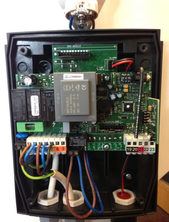


7 Dip Switches GSM connection slot Alarm Connector Mem Button Motor Power Radio Card Knowing your way around the Receiver


8 Radio card 3 LEDS Memory Button


9 Rubber grommet Bottom Slat Transmitter Dip Switches Program Button Red LED Ensure that all 6 screws are used to secure the lid to the unit and that the rubber grommet is in place. Failure to do so will invalidate the warranty
10 Dipswitches on receiver The receiver has three dip switches Dip switch 1 and 2 should always be on (in the up position) Dip switch 3 is user settable (auto return time on/off
11 What do the dipswitches do? Dip switch 1 This feature is used to disable the safety edge, to be used in exceptional circumstances only! On = wireless edge Off = wired edge Switch power off Switch power back on Move dipswitch to required position Press and hold the Mem button for 5 seconds to confirm the setting Verification 6 beeps = programmed for wired edge 7 beeps = programmed for wireless
12 What do the dipswitches do? Dip switch 2 On = Impulse operation Off = Deadman operation Dip switch 3 On = Autoclose activated Off = Autoclose deactivated

13 Dipswitches on Bottom slat transmitter Dipswitch 1 should ALWAYS be on Dip switch 2 On = System test (times out after 30 secs)

14 Testing the bottom slat transmitter and wiring The bottom edge can be tested to confirm if the wiring and bottom slat transmitter are functioning correctly. Put dipswitch 2 on Within 30 seconds squeeze firmly the bottom edge rubber The red light will activate upon each squeeze Return dipswitch 2 to the off position Dip Switches Red light activates Important This function will time out after 30seconds so if the time has elapsed put the switch off and on again
15 So. Board has power! Limits have been set! Now what? 2 very simple tasks! 1) Pair the bottom slat transmitter to the receiver 2) Code in your transmitters


16 Pairing the bottom slat transmitter Action Press P button on radio card for 2 seconds Press P button on bottom slat transmitter for 2 seconds Verification middle light on radio card will start to flash To check if its paired Press and hold the P button on bottom slat transmitter Solid red LED on the BST = Paired Flashing LED on the BST = Not paired Press P button for 2 seconds Now press P button for 2 seconds
17 The Mem Button Mem button is used to add and delete transmitters and accessories 8 different modes MEM Button
18 The Mem Button modes! Mode 1-1 press = Remote operates as up/stop/down all on one button Mode 2-2 presses = Remote operates as up on one button/down on another button Mode 3-3 Presses = Allows a channel on the remote to toggle lights on and off Mode 4-4 presses = Deletes a single channel/button Mode 5-5 presses = Deletes all channels/buttons Mode 6-6 Presses = Codes in a 4 channel remote as up on one button, down on another plus adds a light button and stop button Mode 7-7 presses = Used to code in a bi-directional remote control Mode 8-8 presses = Used to code in an alarm

 Press button on transmitter")
19 Adding a transmitter Mode 1 - Up/stop/down Action Press P button on receiver once and hold (long beep) Press button on transmitter (short beeps)
 Press button on transmitter(short")
20 Adding a transmitter Mode 2 - Up on one button/down on another button Action Press P button on receiver twice and hold on the second press (long beep) Press button on transmitter(short beeps)
21 Programming the light Mode 3 Toggle light on and off Action Press P button on receiver three times and hold on the third press Press button on transmitter (short beeps)
22 Deleting a channel Mode 4 Delete a single channel Action Press P button on receiver four times and hold on the fourth press (long slow beeps) Press relevant button on transmitter to delete that channel (long solid beep)
23 Deleting all channels Mode 5 Delete all channel/buttons Action Press P button on receiver five times and hold on the fifth press (short beeps for 8 seconds long beep for 2 seconds) Release your finger after the long solid beep stops (aprox 10 secs)
24 Adding a transmitter Mode 6 Quick set up for a 4 channel remote Action Press P button on receiver six times and hold on the sixth press (long beep) Press relevant button on transmitter (long solid beep)

 Press relevant button on transmitter (long solid beep) Having this function allows the")
25 Adding a bi-directional transmitter Mode 7 Quick set up for a Bi-directional remote Note Only available on compatible remotes Note The bi-directional function must be activated before programming the transmitter. Press the MEM (P1) button 14 times: you will hear one of the following tones: Action Bi-directional active = continuous tone Bi-directional inactive = beeping Press P button on receiver seven times and hold on the seventh press (long beep) Press relevant button on transmitter (long solid beep) Having this function allows the user to see the status of their garage door simply by pressing the ask channel Refer to Mode 2 to add the transmitter
26 Adding an alarm Mode 8 Adding an alarm to the system Action Press P button on receiver eight times and hold on the eighth press (long beep) Tap the wireless shock sensor against a hard surface before fitting to the door (short beeps)
27 Programing one remote from another Action Press the back of the transmitter P3 with a paperclip once, then release (long beep) Then press the channel on the front of the same transmitter (long beep) Now press a button on your new and unused transmitter (short beeps)
28 Programing Autoclose Action Put Dip switch 3 on (short beep) Switch the power off and back on again Within 30 seconds start the following sequence Press and hold the P3 button on the back of the transmitter until it beeps Now press it 8 times in quick succession (8 short beeps one on each press) Wait for 2 beeps Press P3 again to start the timer (single beep) Wait your required time (min 5 secs, max 90 sec) Press P3 to stop the timer (single beep) Note : The door needs to be fully open in order to autoclose
29
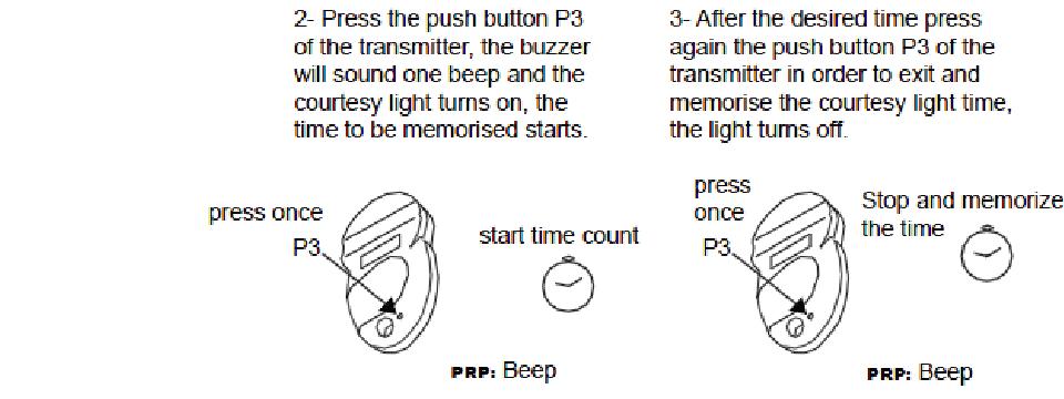
30 Programing light timer Action Switch the power off and back on again Within 30 seconds start the following sequence Press and hold the P3 button on the back of the transmitter until it beeps Now press it 5 times in quick succession (5 short beeps, one on each press) Wait for 3 beeps Press P3 again to start the timer (single beep) Wait your required time (min 60secs, max 12 hrs) Press P3 to stop the timer (light switches off)
31


32 Adding an alarm The sounder will be provided separately to the receiver Simply screw it into the bottom of the receiver (after removing the knockout Plug the pre-connected cable into the terminal marked alarm
33 Adding an alarm Mode 8 Adding an alarm to the system Action Press P button on receiver eight times and hold on the eighth press (long beep) Tap the wireless shock sensor against a hard surface before fitting to the door (short beeps)


34 Adding an alarm Attach the sensor on the bottom slat next to the CE label, not the centre of the door. Insert the provided battery Set the sensitivity accordingly

35 Adding a Magnet If the floor is not level, you have three options, level the floor, pack out the nylon blocks in the bottom slat or fit a wired magnet (must be ordered separately). The magnet shuts down the safety edge 10 cm from the floor Fit the magnet as shown in the picture on the next page the magnet should be fitted to the second slat from the bottom and the sensor should be fitted level with the third slat. There should be a maximum of 2cm between them Wire in the magnet to terminals 22 and 23 Brown 22 White - 23

36 Adding a Magnet Now you need to program the closing time NOTE The door should be in the closed position when starting this procedure NOTE The door will only operate in deadman during programing mode Switch the power off and back on again Within 30 seconds start the following sequence Press and hold the P3 button on the back of the transmitter until it beeps Now press it 10 times in quick succession (10 short beeps, one on each press) Wait for 1 beep Open the door with the remote (beep) The door will be on hold to run Close the door with the remote (beep) The door will be on hold to run Send the door all the way to the top once before testing if the magnet works Fit the magnet to the second slat from the bottom. Then fit the wired contact level with the third slat from the bottom
37 Adding a Magnet
38 Adding a battery back up Disabling anti entrapment If you are using a battery back up, you need to disable the anti entrapment feature and ensure that a hood is fitted to the garage door to protect the user from entrapment Switch the power off and back on again Within 30 seconds start the following sequence Press and hold the P3 button on the back of the transmitter until it beeps Now press it 4 times in quick succession and HOLD for 5 secs on the fourth press If you hear 1 beep the motor torque is disabled and the unit is ready to be used with a battery back up If you hear 2 beeps the motor torque is enabled.
39 Adding a battery back up Disabling anti entrapment
40 Programming wall transmitter Note A wall transmitter is nothing more than a fancy looking remote and can be programmed in the same way Action Press and hold the Mem button on the receiver with either one press or two depending how you want your wall switch to operate, then press the top button on the wall transmitter Note The wall transmitter can be used to operate the door in up/stop/down or up on one button and down on another. The lights can also be operated on the wall transmitter Applicable wall transmitters can also show the status of the door eg open/closed etc (by pressing the ask button)
41 Programming keypad Note The keypad operates off a 5 digit code Factory code is To operate the door press the code and then number 1 Action To program the keypad to the door Enter the factory code Press and hold the Mem button on the receiver Press 1 on the keypad (series of short beeps) To program the light, press the Mem button three times then press the B button on the keypad
42 Changing keypad code Note The keypad operates off a 5 digit code Factory code is Action Remove the back cover Enter the factory code Press the white button on the back of the keypad Enter your new 5 digit code Re enter your 5 digit code
43 Programming two doors/multichannel Note All receivers and remotes are multichannel by default Action Press the Mem button on door A, press the relevant button on the transmitter Press the Mem button on door B, press a different button on the same the transmitter Note It is best practice to have power to only one door at a time whilst coding in a multichannel application, this ensures that you do not accidently code the remote to both doors
 Now press the button on your master remote control")
44 Activating holiday mode This allows the user to disable the buttons on the front of the receiver To lock Press and hold the stop button on the front of the receiver for 5 secs (beep) The led will flash slowly to indicate that the unit is in holiday mode To unlock Press and hold the stop button on the front of the receiver for 5 secs (beep) Now press the button on your master remote control (beep) The door is now out of holiday mode
45 Troubleshooting Beeps! 1 beep - The sensor for the magnet system is set too high. Lower the sensor so that the magnet passes it just before the door hits the floor. 2 beeps - Check that the motor is connected - Check that the wiring is correct - Check that both limits have been set - Reconnect the test lead, check the limits and repower the board NOTE The door can be used in hold to run by simply pressing and holding the operating button for 5 seconds
 correctly wired,")


46 Troubleshooting Beeps! 5 beeps - Is the bottom slat transmitter (BST) correctly wired, check that the wires are securely in place and that the colors match the corresponding numbers - Make sure the batteries in the BST are located correctly, remove them and re-insert - Check dip switch 1 on bottom slat transmitter is set to on - Look for damage to the cables as they enter the bottom slat transmitter


47 Troubleshooting Beeps! 5 beeps -Test the bottom slat transmitter circuitry, see previous page - Press and hold the p button on the bottom slat transmitter to ensure that it has paired to the radio card
48 Troubleshooting A series of short rapid beeps Bottom slat transmitter batteries are going flat, only replace with 3.6 Volt. Even when replaced the system will continue to beep for one minute whilst its establishes the integrity of the new batteries The door hits the floor and then retracts a few inches - The door is sensing imperfections in the floor, check that the floor is level, you may need to level the floor, pack out the nylon blocks in the end of the bottom slat or fit a supplied magnet No beeps and door is unresponsive check link is present between terminals 21 and 22 - Check that remotes that you are using are coded into the system
Marantec bi linked Radio Accessories Service
 Marantec bi linked Radio Accessories 1 45 Service 2015.08 Impressions transmitters 2 45 Service 2015.08 Impressions wall controls 3 45 Service 2015.08 bi linked technology Simple encoding (e. g. Multi-Bit)
Installation And Programming Instructions For Profile Series With RF Technology
 Installation And Programming Instructions For Profile Series With RF Technology A7691A www.sargentlock.com 1 Table of Contents General Description Page 2 3 4 5 6 7 Installation of RF Technology Lock...1
Lazerpoint TM RF RX-91 Basic Receiver Installation Instructions
 Lazerpoint TM RF RX-91 Basic Receiver Installation Instructions Ver. 1.01 Section 1 General Description Camden Lazerpoint Radio Controls comprise the following models: - CM-TX-9 Wall switch ready transmitter
Parts. Backplate. Battery Cover. Backup Key. Touchscreen Assembly. Inside Assembly. Thumbturn. Strike. Reinforcement Plate. Bolt.
 Quick Start Guide Backplate Backup Key Battery Cover Touchscreen Assembly Parts Strike Bolt Inside Assembly Thumbturn Reinforcement Plate Set Screw Reinforcement Screws Inside Assembly Screw Backplate
COD GB / 1.0 RBAND/UMS - RBAND/CSM
 INTRODUCTION DESCRIPTION The RadioBand system is designed of Industrial, Commercial and Domestic door and gate applications where a safety edge is used. The system provides a wireless system replacing
HANDS-FREE KEYLESS ENTRY AUTHF500
 Mount in Dry Location Install Fuses Good Required Use High Amp Relay Remote Transmitter Turn power on. For a successful communication between the main unit and transmitter the on the transmitter will blink
Operating Instructions
 LR650 Operating Instructions This product is an accessory or part of a system. Always read and follow the manufacturer s instructions for the equipment you are connecting this product to. Comply with all
INSTRUCTION MANUAL VHF FM TRANSCEIVER TK-7102H UHF FM TRANSCEIVER TK-8102H KENWOOD CORPORATION B (M)
") INSTRUCTION MANUAL VHF FM TRANSCEIVER TK-7102H UHF FM TRANSCEIVER TK-8102H KENWOOD CORPORATION B62-1596-00 (M) 09 08 07 06 05 04 03 02 01 00 THANK YOU! We are grateful you chose KENWOOD for your personal
INSTRUCTION MANUAL VHF FM TRANSCEIVER TK-7102H UHF FM TRANSCEIVER TK-8102H KENWOOD CORPORATION B62-1596-00 (M) 09 08 07 06 05 04 03 02 01 00 THANK YOU! We are grateful you chose KENWOOD for your personal
120x165mm. 85x165mm TEMPLATE. ELECTRONIC DEADBOLT model no.: & & Toll-free Number:
 20x65mm 85x65mm ELECTRONIC EABOLT FOR BACSET 2 3/4" ( 70 mm) FOR BACSET 2 3/8" ( 60 mm) Ø 2 /8" ( 54 mm ) Toll-free Number: -800-268-659 IMPORTANT: Please read this manual carefully before installing this
R PROFLAME Instruction Book Collection
 9.956.028 R00 584 PROFLAME Instruction Book Collection 4-17 18-29 584 PROFLAME System 30-39 Appendix: DIP SWITCH NUMBER (0=ON 1=OFF) 40-41 4-17 Fig. 1 The SIT is a device that allows, in conjunction with
TEAM DIGITAL. SMC4 Servo & Motor Controller
 16 CV# Function/Default Value CV# Function/Default Value 28 reserved - 73 Servo 3 Behavior 0 29 Decoder Configuration 0 74 Servo 4 Behavior 0 30 reserved - 75 Output Flash 0 31 Ops Mode Loco Address 1
Hardware Installation. Do this first:
 1 Do this first: Hardware Installation Need some help? Here s what you ll need: 4 AA Batteries Phillips screwdriver Visit us online. support.remotelock.com We re here to help. 1 (877) 254 5625 support@remotelock.com
SUNDIAL Light Dimmer. User's Manual
 Light Dimmer User's Manual 1. PRECAUTIONS Although fuses at the input and outputs of the controller protect its circuits in case of an overload or overvoltage, we recommend installing an additional protection
Instructions for programming and use Starline Roldeck - floorpanel control RD-2001
 Instructions for programming and use Starline Roldeck - floorpanel control RD-2001 Microprocessor-based Roldeck control Copyright Starline Technical Support BV. The Netherlands. Alle rechten voorbehouden.
impact VC-500LR Monolight INSTRUCTIONS
 impact lighting equipment and accessories VC-500LR Monolight INSTRUCTIONS Congratulations on your purchase of the Impact VC-500LR Monolight. We feel that it will contribute much to your photographic skill
GROUP OF COMPANIES. MERLIN STEALTH Electric Fence Energizer INSTALLERS MANUAL
 GROUP OF COMPANIES MERLIN STEALTH Electric Fence Energizer INSTALLERS MANUAL Revision 1.5 23 February 2007 : INSTALLERS MANUAL Table of Contents 2 INTRODUCTION.. 3 INSTALLER OPTIONS...... 4-11 ALARM SETTING
DOOR OPENER WITH TIMER AND LIGHT SENSOR
 DOOR OPENER WITH TIMER AND LIGHT SENSOR THE PACKAGE ALSO INCLUDES: 4 batteries, 4 screws, instructions and a installation DVD CONTENT 1 Name & Function of Operation Buttons 2 How To Setup The Door Opener
IRIS \ IRIS-I QUICK SET-UP GUIDE STEP 1 INSTALL
 IRIS \ IRIS-I QUICK SET-UP GUIDE STEP 1 INSTALL Confirm contents of package: 1 sensor, 1 cable, 1 wide lens (default), 1 narrow lens, mounting template, User s Guide. Install the sensor at the desired
IMPORTANT SAFEGUARDS READ AND FOLLOW ALL SAFETY INSTRUCTIONS SAVE THESE INSTRUCTIONS FOR FUTURE REFERENCE
 FSP-2X1 Digital High/Low Pir Fixture Integrated Sensor INSTALLATION INSTRUCTIONS IMPORTANT SAFEGUARDS When using electrical equipment, basic safety precautions should always be followed including the following:
2016 Motorized Shades Basic Programming
 About Motorized Shades: 2016 Motorized Shades Basic Programming A. THE (DUAL VOLTAGE) TWO WIRE 25TE MOTOR REQUIRES 120V AC OR 240V AC. B. BATTERIES ARE (NOT INCLUDED) FOR 12V 25CE BATTERY MOTORS. EACH
G703. Installation instructions. residential gate opener for sliding gates. remote control openers security at your fingertips
 remote control openers security at your fingertips G703 residential gate opener for sliding gates Installation instructions Toll free helpline Please have your serial number and model name available before
1: White buttons Used by the user on a daily basis. 2: Grey buttons Used only upon first startup.
 Fig. 1 Lock/ unlock 30 1000 Light 1 100 300 zone 1 Learn actual lux LED 600 2000 0,4 0,6 0,8 1,0 1,2 Time 1 Light 2 zone 2 1,4 1,6 Factor of lux zone 1 Pulse 2min 5min Time Time 2 10min 15min 30min 1 2
Installation Guide. Cue Front Unit (Code and Key) Cue Front Unit (RFID) Cue Rear Unit (Latch and Bolt)
 Cue Front Unit (RFID) Cue Rear Unit (Latch and Bolt)") Installation Guide Cue Front Unit (Code and Key) Cue Front Unit (RFID) Cue Rear Unit (Latch and Bolt) Table of Contents Before Lock Installation3 Surface Mount Installation For door thickness measuring
Installation Guide Cue Front Unit (Code and Key) Cue Front Unit (RFID) Cue Rear Unit (Latch and Bolt) Table of Contents Before Lock Installation3 Surface Mount Installation For door thickness measuring
Typical Wiring Connection Diagram 625DC1 RECEIVER 12VDC GROUND FROM REGULATED SOURCE 12VDC GROUND (BLACK WIRE)
") 625DC READ CAREFULLY BEFORE AND WHILE INSTALLING 625DC1 Typical use is for a SINGLE MOTOR SALT SPREADER WITH VIBRATOR CONTROL. NOTE TRANSMITTER HAS BEEN PROGRAMMED TO THE RECEIVER SEE PAGE 4 FOR PROGRAMING
625DC READ CAREFULLY BEFORE AND WHILE INSTALLING 625DC1 Typical use is for a SINGLE MOTOR SALT SPREADER WITH VIBRATOR CONTROL. NOTE TRANSMITTER HAS BEEN PROGRAMMED TO THE RECEIVER SEE PAGE 4 FOR PROGRAMING
Jarvis standing desk. Assembly instructions. For assembly assistance, visit fully.com/howtojarvis or call or
 Jarvis standing desk Assembly instructions For assembly assistance, visit fully.com/howtojarvis or call 888-508-3725 or email support@fully.com Thank you for choosing a Jarvis desk from Fully. Cautions
WIRELESS DIMMER FOR HEATING
 TELECO AUTOMATI SRL - Via dell Artigianato, 16-31014 Colle Umberto (TV) ITALY TELEPHE: ++39.0438.388511 FAX: ++39.0438.388536 - www.telecoautomation.com This document is the property of Teleco Automation
EscapeKeeper & EscapeKeeper JR
 EscapeKeeper & EscapeKeeper JR OPERATING MANUAL 877-815-5744 or 905-803-9274 www.frightideas.com Contents Getting Familiar with your EscapeKeeper...4 Connections and Controls... 4 Your Current Firmware
Operation Manual for the TS_SW3G023 3G/GPRS Signal Analyser.
 Operation Manual for the TS_SW3G023 3G/GPRS Signal Analyser www.gprsmodems.co.uk sales@gprsmodems.co.uk Table of Contents Page No. 1 Description.. 3 2 3G/GPRS Signal Analyser Contents. 3 3 Quick Start
Note: A 6-button hand control XX or X is required to access service mode.
 PROGRAMMING GUIDE FOR CEILING LIFT 910XXXX, 911XXXX, 912XXXX, 913XXXX, 923XXXX, LDXXXX, LFXXXX V4, V4i, V10, MAXI SKY 600, MAXI SKY 1000, VOYAGER DUO, V5 DUO 1. User Service Mode page 2 2. Technical Service
Micro Wizard Instructions K1 KIT ASSEMBLY INSTRUCTIONS With Remote Start Switch
 K1 KIT ASSEMBLY INSTRUCTIONS With Remote Start Switch Kit Contents: (If you have ordered the Quick Mount or have a Best Track, the contents of your kit will differ from this list. Please refer to the mounting
KICHFS1002 ONE TOUCH ENGINE START KIT WITH RFID. Parts Included: 1 ECO 1 HF500 1 KICSWBM22**
 KICHFS1002 Parts Included: 1 ECO 1 HF500 1 KICSWBM22** Mount in Dry Location Install Fuses Good Ground Required Use High Amp Relay Remote Transmitter Turn power on. For a successful communication between
Dear Valued Customer,
 Dear Valued Customer, Thank you for choosing Listen! All of us at Listen are dedicated to provide you with the highest quality products available. We take great pride in their outstanding performance because
580A Automatic Cable Tying Machine 580A
 Automatic Cable Tying Machine 580A Contenido Regular Information...3 Technical parameters:...5 Operation Instruction....6 Trouble Shooting....8 Maintenance....9 After-sales Service...9 Safety Instructions....10
RADIO ANTI TWO-BLOCK SYSTEM
 BB-550 TM RADIO ANTI TWO-BLOCK SYSTEM INSTALLATION MANUAL GREER Company 1918 East Glenwood Place, Santa Ana, CA 92705 Tel: (714) 259-9702 FAX (714) 259-7626 BB-550 TM Radio Anti Two-Block System PN W250000
AMANO PIX-21. Electronic Time Recorder. Operation Manual
 AMANO PIX-21 Electronic Time Recorder Operation Manual External View Page 1 Removing the Cover & Packing Materials 1. Lift the printer block and remove the spacer. 2. Insert the key provided and turn clockwise
DC Instruction Manual. Professional FM Transceiver
 DC-1074 Professional FM Transceiver Instruction Manual Use of the citizen band radio service is licensed in Australia by ACMA Radiocommunications (Citizen Band Radio Stations) Class Licence and in New
GETTING STARTED. Radio layout. LCD display with icons
 GETTING STARTED Radio layout LCD display with icons 1. Key lock button 2. Battery meter 3. Main channel indicator 4. Scan icon 5. Roger beep indicator 6. CTCSS sub-channel indicator 7. VOX indicator 1
WARNING: Prior to installation, turn the power off to the vending machine and unplug it from its power source. Also, make sure to level the machine.
 Installation of Gum and Mint Tray for National 147, 157, 167 Important Note: Please read all instructions thoroughly before continuing with installation of kit. If you are having problems installing the
Gardall Locks Operating Instructions
 Gardall Locks Operating Instructions Mechanical Combination Lock Turn Left stopping when the first number comes to the mark the 4th time. 1. Turn Right stopping when the second number comes to the mark
AutoAnchor 570 OWNER S MANUAL
 AutoAnchor 570 OWNER S MANUAL AutoAnchor 570 Owner s Manual TABLE OF CONTENTS Part 1 Important Information 4 Part 2 Installation 7 Part 3 Set Up 18 Part 4 Operation 30 Part 5 Maintenance 36 Part 6 Troubleshooting
ET Water SmartWorks Panel Installation Guide
 ET Water SmartWorks Panel Installation Guide You are installing a new piece of equipment that retrofits into an existing irrigation controller in order to create a weather-based irrigation control system.
UR200SI / UR200WE ENGLISH
 ENGLISH Hersteller Wörlein GmbH Tel.: +49 9103/71670 Gewerbestrasse 12 Fax.: +49 9103/716712 D 90556 Cadolzburg Email. info@woerlein.com GERMANY Web: www.woerlein.com UR200SI / UR200WE ENVIRONMENTAL PROTECTION
Keycards come with an imbedded RFID chip and antenna, there is no battery in the keycards. The keycards are encrypted and only
 Index Keycards 02 The following is a description of the type of Keycards and function 03 Programming and Initialization of the RFID Lock 04 Procedure for Initialization 05 Programming- Adding Keycards
Micro Wizard Instructions
 How to install your Fast Track flashing light display timer model K1 with optional remote start switch (If you have ordered the Quick Mount or have a Best Track, disregard this section and refer to the
RADIOBAND V3 Programming & Installation Manual
 RADIOBAND V3 Programming & Installation Manual Radioband V3 User s Manual Introduction The RadioBand system is designed for Automatic Gates, Commercial and Domestic door applications where a safety edge
LOAD AWG Solid CU Wire Only LINE NEUT FSP-211. High/Low PIR Occupancy Sensor 230 VAC, 50 Hz 1200W max ballast 5E4
 DESCRIPTION AND OPERATION The is a motion sensor that dims lighting from high to low based on movement. This slim, low-profile sensor is designed for installation inside the bottom of a light fixture body.
LIGHT- INDUSTRIAL SLIDING GATE OPERATORS
 D5-Evo, D10 and D10 Turbo Pocket System Configuration Guide TM TM TM LIGHT- INDUSTRIAL SLIDING GATE OPERATORS Prior to commissioning the system, please ensure that you have connected the wiring of all
Wireless valve actuator for bidirectional EnOcean communication. The SAB05 combines with message server and enocean transmitter.
 SAB05 EasySens wireless radiator valve actuator for room temperature control Data Sheet Subject to technical alteration Issue date: 26.11.2015 Application Wireless valve actuator for bidirectional EnOcean
IMPORTANT: READ AND UNDERSTAND ALL INSTRUCTIONS BEFORE BEGINNING INSTALLATION
 INSTALLATI INSTRUCTIS Model: RB-G-K10 IMPORTANT: READ AND UNDERSTAND ALL INSTRUCTIS BEFORE BEGINNING INSTALLATI The Miller Edge RBand Monitored Gate Edge Transmitter/Receiver system is intended to provide
GLR43308 and GLR2708. Setup and programming instructions. for the 8 channel Gigalink receiver. Programming Videos
 GLR43308 and GLR2708 Setup and programming instructions for the 8 channel Gigalink receiver Programming Videos www.elsema.com NOTES IMPORTANT WARNING AND SAFETY INSTRUCTIONS All installations and testing
CONTENTS. Accessories and Components System Unit and Joystick Assembly and Charging the Battery Jeotech Using Phases...
 CONTENTS Accessories and Components... 3 System Unit and Joystick... 4 Assembly and Charging the Battery... 6 Jeotech Using Phases... 9 What is ground setting and how it is done?... 11 Steps for the Ground
INSTRUCTION MANUAL TX3400 UHF TRANSCEIVER
 INSTRUCTION MANUAL TX3400 UHF TRANSCEIVER CONTENTS Contents................................... 2 Introduction................................ 2 Features.................................... 2 Operation..................................
MobileRadio. Owner'sManual
 EMH MobileRadio Owner'sManual TABLE OF CONTENTS Introduction... 1 Basic Operation... 2 Code Guard Operation... 3 EMH Radio Controls... 4 Button Functions... 4 Built-in Features... 7 Keypad Microphone Operation...
UPLIFT 2-Leg Height Adjustable Standing Desk
 UPLIFT -Leg Height Adjustable Standing Desk Also watch our assembly video http://bit.ly/9ywwh DIRECTIONS FOR ASSEMBLY AND USE TABLE OF CONTENTS PAGE Safety and Warnings Usage Parts List Assembly Instructions
IMPORTANT! Please take the time to read through the manual before you start to install/program your equipment.
 PRODUCT DESCRIPTION IMPORTANT! Please take the time to read through the manual before you start to install/program your equipment. The systems KRC11, 12, 13 and 14 consists of two parts: the transmitter
opponent; your phaser says tagged. Number of tags is shown on your display after the letter T. How to Play:
 Quick Start Guide lasertag.com.au/content/getting-started THE STANDARD BOX INCLUDES: Getting Started FAST: 5x phasers Red 1x Spare 5x phasers Blue PLUS 1 x Master Controller & 2 x Medic Boxes STANDARD
LK Wireless Room Control Cq
 LK Wireless Room Control Cq Description LK Wireless Room Control Cq consists of a LK Room Thermostat Cq-n (transmitter) and a LK Receiver Unit Cq 8 (8 channel receiver unit). The range also includes a
MD9300 Metal Detector OWNER S MANUAL
 Famous Trails Anaheim, California Phone (714) 701-9671 Fax (714) 701-9672 Toll Free: (877) 97SCOPE www.famoustrails.com MD9300 Metal Detector OWNER S MANUAL CONTENTS Assembling the Detector----------------------------------------------------------
LMLR-710 (Plug-in type door chime receiver) LMLT-711 (push unit door chime transmitter)
 LMLT-711 (push unit door chime transmitter)") MODEL: LMLR-710 (Plug-in type door chime receiver) LMLT-711 (push unit door chime transmitter) FEATURE: * 67 million self-learning coding RF wireless operation system. No interference with neighbors. *
MODEL: LMLR-710 (Plug-in type door chime receiver) LMLT-711 (push unit door chime transmitter) FEATURE: * 67 million self-learning coding RF wireless operation system. No interference with neighbors. *
The Smallest, Quietest & Safest Garage Door Operator in the World!
 ZAP Technical Instruction The Smallest, Quietest & Safest Garage Door Operator in the World! Function Programming Series controller applicable to: 800 II G, 800 II, 8800 II, 8800 II HP, 8850 These functions
WIRELESS Energy Monitor - Smart Meter
 Energy saving made simple MONITOR CONTROL SAVE WIRELESS Energy Monitor - Smart Meter Monitors your electricity use and cost in real time Instruction Manual EW4500 IMPORTANT Please retain your Instruction
Operation. Section 4. Additional Information. Operation 4-1
 4-1 Section 4 WARNING: Allow only personnel with appropriate training and experience to operate or service the equipment. The use of untrained or inexperienced personnel to operate or service the equipment
2011 / Circuit Tracer
 INSTRUCTION MANUAL 2011 / 00521 Circuit Tracer Read and understand all of the instructions and safety information in this manual before operating or servicing this tool. 52044992 2008 Greenlee Textron
CL4500 Installation Instructions
 CL4500 Installation Instructions Box Contents Check the contents of the box are correct according to the model 4510 4520 1 Front Plate 2 Back Plate 3 Lever Handles 4 Gaskets 5 Sprung Spindle (x1) 6 Spring
First of all, power up the handsets and controllers!
 First of all, power up the handsets and s!. Power the handsets: mains recharged handsets are supplied with NiCad batteries already fitted battery recharged handsets are supplied with a lithium battery
TRACEABLE RADIO-SIGNAL REMOTE THERMOMETER INSTRUCTIONS
 TRACEABLE RADIO-SIGNAL REMOTE THERMOMETER INSTRUCTIONS SPECIFICATIONS Display Main unit: two-line 1" LCD Remote unit: 3 /8" LCD Temperature Main unit IN range: 9.9 to 158.0 F ( 9.9 to 70.0 C) Main unit
LSC Radio User Guide Information and Guidelines
 LSC Radio User Guide Information and Guidelines The following user guide applies to both the Motorola VL50 and CLS1410 Radio s. Below are guidelines established for usage. 1) Radios and headsets are to
Specification. What s Included. Power Supply DC, 9V Battery (2) Emitter 10mA Receiver 30mA. Working Current (Max) Signal Output Electrical Status
 Emitter 10mA Receiver 30mA. Working Current (Max) Signal Output Electrical Status") Specification Product PITS-TP-2 Power Supply DC, 9V Battery (2) Working Current (Max) Signal Transmission Format Signal Output Electrical Status Transmission Distance Dimension Weight Emitter 10mA Receiver
Specification Product PITS-TP-2 Power Supply DC, 9V Battery (2) Working Current (Max) Signal Transmission Format Signal Output Electrical Status Transmission Distance Dimension Weight Emitter 10mA Receiver
CordLift WireFree Programming & Operation Instructions CT-32RT-12V
 New & Improved ming New programming applies to all CordLift WireFree motors released after August 2006. These motors will have new packaging as well as a new colored label on them. Before you begin Motors
Flat Sheer Shade owner's handbook
 Flat Sheer Shade owner's handbook INSTALLATION INSTRUCTIONS Step 1. Check Package Contents Mounting hardware kit includes the following: Part a.mounting Brackets Quantity 2 for shades up to 45 wide 3 for
 www.greenelectricalsupply.com Installation Guide Model: WLVD Wireless Low Voltage Dimmer (Receiver) Specifications: Power Supply 24 V DC Place on 24V power line prior to light load. 10A Maximum Load Package
WARRANTY. Long Range Systems, LLC, 20 Canal St, Suite 4N, Franklin, NH 03235
 WARRANTY Long Range Systems, Inc. warrants the trap release product against any defects that are due to faulty material or workmanship for a one-year period after the original date of consumer purchase.
Presentation 90. Description 92 The external units 92 External caller unit 92 The controller unit 92 The indoor station 93
 Contents Presentation 90 Description 92 The external units 92 External caller unit 92 The controller unit 92 The indoor station 93 Installation of the DoorPhone 95 Installation rules 95 Installation of
Rechargeable Motivia Motorization Made Simple
 Rechargeable Motivia Motorization Made Simple Horizontal Sheer Shadings smithandnoble.com HOW TO OPERATE YOUR MOTORIZED SHADES Operate Your Shade with A Motivia Multi-Channel Remote For added protection,
Before Lock Installation Surface Mount Installation. Door Preparation. For door thickness measuring between.01" -.91" (0.2 mm - 23 mm)...
...") Installation Guide Before Lock Installation... 3 Surface Mount Installation For door thickness measuring between.01" -.91" (0.2 mm - 23 mm)... 4 Required Components... 4 Installation... 5 Door Preparation
Installation Guide Before Lock Installation... 3 Surface Mount Installation For door thickness measuring between.01" -.91" (0.2 mm - 23 mm)... 4 Required Components... 4 Installation... 5 Door Preparation
ProHUNTER OWNERS MANUAL
 TM ProHUNTER OWNERS MANUAL TM 400-597-1 1 400-597-1 2 TM SPORTDOG PROHUNTER 2400 REMOTE TRAINER INSTRUCTION MANUAL Thank you for purchasing the ProHunter 2400, one of the finest training systems available
Schlage Control Smart Locks
 Schlage Control Smart Locks with Engage technology User guide Schlage Control Smart Locks with Engage technology User Guide Contents 3 Warranty 4 Standard Operation 4 Operation from the Inside 4 Operation
PMR446 Radio Instruction Manual
 Tectalk PRO PMR446 Radio Instruction Manual Thank you for purchasing this radio. All our products are built to offer excellent value by combining advanced features, great design and manufacturing quality.
ABM International, Inc.
 ABM International, Inc. Lightning Stitch required 1 1.0: Parts List head and motor assembly (Qty. 1) Reel stand (Qty. 1) Needle bar frame clamp (Qty. 1) Motor drive (Qty. 1) 2 Cable harness with bracket
TEAM DIGITAL. Servette TM Single Servo Controller
 12 7 Summary of Configuration Variables CV# Function/Default Value CV# Function/Default Value 1 Servo Address 1 43 reserved - 2 reserved - 44 Sec Input Control 26 3 Servo Move Range 15 45 reserved - 4
MTC-2 highlight features: ACU for Flakpanzer Gepard highlight features: Contents. MTC-2 and ACU User Manual V4.2 (Flakpanzer Gepard Version)
") This manual is written for the ACU for Flakpanzer Gepard. There are some modifications on usage of servo and LED ports. Please also notice that GSU (gun stabilize unit) is not supported. MTC-2 highlight
This manual is written for the ACU for Flakpanzer Gepard. There are some modifications on usage of servo and LED ports. Please also notice that GSU (gun stabilize unit) is not supported. MTC-2 highlight
Pair of PMR446 Two-Way Personal Radios Model: TP391
 Pair of PMR446 Two-Way Personal Radios Model: TP391 USER MANUAL MANUALE D USO MANUEL DE L UTILISATEUR BEDIENUNGSANLEITUNG MANUAL DE USUARIO MANUAL DO USUÁRIO HANDLEIDING BRUKSANVISNING P/N:086L004722-016
ISW-EN7016 Installation Guide
 ISW-EN7016 Installation Guide Survey Kit The items in this product kit are designed to be used by professional security technicians. This product kit is intended for indoor use. Quick Start Guide By following
IMPORTANT: THIS DEVICE MUST BE PROFESSIONALLY INSTALLED. READ AND UNDERSTAND ALL INSTRUCTIONS BEFORE BEGINNING INSTALLATION.
 INSTALLATI INSTRUCTIS Model: RB-G-K10 IMPORTANT: THIS DEVICE MUST BE PROFESSIALLY INSTALLED. READ AND UNDERSTAND ALL INSTRUCTIS BEFORE BEGINNING INSTALLATI. The Miller Edge RBand Monitored Gate Edge Transmitter/Receiver
2400AT 4 I221 I221 1A 1A T T Rev. Rev B. C
 4 I2211AT Rev. Rev.B I2211AT C 2400AT Contents 1. Introduction 2. Components 3. Before operation 4. Setting up your Model 2400AT 4.1 setting the year 4.2 setting date 4.3 setting time 4.4 setting day line
RTS Reactive Target System
 RTS Reactive Target System RTS Electronic Target System Operating and User s Manual Introduction RTS (Reactive Target System) introduces a significant technological leap in erecting and managing wireless
Installers guide Deadbolt 02.
 Installers guide Deadbolt 02. version 0.7.1 Specifications Model igloohome Smart Deadbolt 02 Material Zinc Alloy Current Rating (Standby) ~30uA Current Rating (Active) ~200mA Batteries 4 x AA Alkaline
PERSONAL RECORD KEEPING
 2 P R O 3 7 0 A s s e m b l y i n s t r u c t i o n s PERSONAL RECORD KEEPING Tip: Record the serial numbers of your Octane Fitness elliptical in the spaces below. This will make it easier for you to obtain
Wireless Data Gathering Panel (DGP) Model AL-1231
 Model AL-1231") g GE Security Wireless Data Gathering Panel (DGP) Model AL-1231 Installation & Programming Guide Installation and Programming Guide Wireless DGP AL-1231 Part number: 466-2025-US Rev. H April 2005 Contents
g GE Security Wireless Data Gathering Panel (DGP) Model AL-1231 Installation & Programming Guide Installation and Programming Guide Wireless DGP AL-1231 Part number: 466-2025-US Rev. H April 2005 Contents
Scoreboard Operator s Instructions MPCW-7 Control
 Scoreboard Operator s Instructions MPCW-7 Control Some features on the keyboard overlay may not be included on the particular model being operated. Since 1934 2/18/2016 135-0215RC These Instructions are
Content. Maintenance. Features ENGLISH. 1 transceiver 1 antenna 1 battery pack 1 belt clip 1 fast desktop charger User manual
 ENGLISH Content 1 transceiver 1 antenna 1 battery pack 1 belt clip 1 fast desktop charger User manual If any items are missing, contact your dealer. Maintenance Your Two Way Radio is an electronic product
Driveway Alarm INSTALLATION MANUAL
 WIRELESS ACCESS CONTROLS Driveway Alarm INSTALLATION MANUAL Mounting post Transmitter Receiver Transformer Sensor Kit Includes: Transmitter Module Sensor Receiver Transformer Mounting post (3 pieces) Installation
Vinyl Cutter Instruction Manual
 Vinyl Cutter Instruction Manual 1 Product Inventory Inventory Here is a list of items you will receive with your vinyl cutter: Product components (Fig.1-4): 1x Cutter head unit complete with motor, plastic
FUNTRONIX SCORE-N-TIME TM GAMEROOM EDITION ELECTRONIC SCOREBOARD WITH REAL ALARM CLOCK & DATE. OPERATING MANUAL Model SNT-125G
 FUNTRONIX SCORE-N-TIME TM GAMEROOM EDITION ELECTRONIC SCOREBOARD WITH REAL ALARM CLOCK & DATE OPERATING MANUAL Model SNT-125G Revision: October 27, 2015 1 Thank you for purchasing a Funtronix SCORE-N-TIME
Proximity-Sensor Counter Installation Instruction Model: MRC-PRO
 Proximity-Sensor Counter Installation Instruction Model: MRC-PRO NYS DOT Approval SYSDYNE CORP. 1055 Summer St. 1 st Floor Stamford, CT 06905 Tel: (203)327-3649 Fax: (203)325-3600 Contents: Introduction...
Scoreboard Operator s Instructions MPCW-7 Control
 Scoreboard Operator s Instructions MPCW-7 Control Some features on the keyboard overlay may not be included on the particular model being operated. Since 1934 3/27/2018 135-0217RD These Instructions are
Commercial Series. CP140 Portable Radio. User Guide
 Commercial Series CP140 Portable Radio User Guide Issue: October 2003 CONTENTS Computer Software Copyrights... 2 Radio Overview..... 3 Operation and Control Functions..... 3 Radio Controls.... 3 LED Indicator.....
MFJ ENTERPRISES, INC.
 Screwdriver Antenna Controller Model MFJ-1926 INSTRUCTION MANUAL CAUTION: Read All Instructions Before Operating Equipment! MFJ ENTERPRISES, INC. 300 Industrial Park Road Starkville, MS 39759 USA Tel:
multiscan Radio fingerprint scanner NB870N with master radio keys Installation and operation instructions
 WWW.FUHR.DE multiscan Radio fingerprint scanner NB870N with master radio keys Installation and operation instructions MBW22b-GB/01.19-0 www.fuhr.de These instructions are to be passed on by the fitter
What to do if you buy a model with a Magic Timer. Preliminary Version 0.8
 What to do if you buy a model with a Magic Timer Preliminary Version 0.8 December 2012 Page 1 Table of Contents Page 2 1. Purpose The purpose of this document is to help people get started when they buy