CELLULAR AND MOBILE COMMUNICATIONS
|
|
|
- Roland Preston
- 5 years ago
- Views:
Transcription


1 CELLULAR AND MOBILE COMMUNICATIONS by VIDYA SAGAR POTHARAJU Associate Professor, Dept of ECE,. 1
2 TEXT BOOKS 1.Mobile and Cellular Telecommunications-W.C.Y.Lee 2 nd Edn, Wireless Communications-Theodre.S.Rapport, Pearson education,2nd Edn., Mobile Cellular Communications-Gottapu sashibushan rao,pearson,2012. REFERENCES: 1.Principles of mobile communications-gordon L.Stuber,Springer intl,2nd Edn., Modern Wireless Communications-Simon Haykin,Michael moher,pearson Edu, Wireless Communications theory and techniques,asrar U.H.Sheikh,Springer, Wireless Communications and networking,vijay Garg,Elsevier Publications, Wireless Communications-Andrea Goldsmith,Cambridge University Press,
3 Syllabus INTRODUCTION TO CELLULAR MOBILE RADIO SYSTEMS: Limitations of conventional mobile telephone systems, Basic Cellular Mobile System, First, second, third, and fourth generation cellular wireless systems, Uniqueness of mobile radio environment. Fading-Time dispersion parameters, Coherence bandwidth, Doppler spread and coherence time. FUNDAMENTALS OF CELLULAR RADIO SYSTEM DESIGN Concept of frequency reuse, Co-channel interference, co-channel interference reduction factor, Desired C/I from a normal case in a omnidirectional antenna system, system capacity, trunking and grade of service, Improving coverage and capacity in cellular systems- Cell splitting, Sectoring, Microcell zone concept. 3
4 Conventional Mobile System 4
5 Limitations of Conventional Mobile Telephone Systems One of many reasons for developing a cellular mobile telephone system and deploying it in many cities is the operational limitations of conventional mobile telephone systems: Limited service capability, Poor service performance, Inefficient frequency spectrum utilization. Limited service capability : Each area is allocated with one or more channels. Which is large autonomous geographic zone. The transmitted power should be as high as the federal specification allows. The user who starts a call in one zone has to reinitiate the call when moving into a new zone because the call will be dropped. 5
6 Poor Service Performance In the past, a total of 33 channels were all allocated to three mobile telephone systems. o Mobile Telephone Service (MTS)-40MHz o Improved MTS (IMTS) MJ-150MHz o Improved MTS (IMTS) MK -450MHz 6 channels of MJ serving 320 customers, with another 2400 customers on a waiting list. 6 channels of MK serving 225 customers, with another 1300 customers on a waiting list. The large number of subscribers created a high blocking probability during busy hours. Although service performance was undesirable, the demand was still great. A high-capacity system for mobile telephones was needed. 6
7 Inefficient frequency spectrum utilization The frequency utilization measurement (Mo), is defined as the maximum number of customers that could be served by one channel at the busy hour. Mo = Number of customers/channel Mo = 53 for MJ system,37 for MK system The offered load can then be obtained by A = Average calling time (minutes) x total customers / 60 min (Erlangs) Assume average calling time = 1.76 min. A1 = 1.76 x53 x 6 / 60 = 9.33 Erlangs A2 = 1.76 x 37 x 6 / 60 = 6.51 Erlangs (MJ system) (MK system) 7
8 If the number of channels is 6 and the offered loads are A1 = 9.33 and A2 = 6.51, then from the Erlang B model the blocking probabilities, B1 = 50 percent (MJ system) B2 =30 percent (MK system), It is likely that half the initiating calls will be blocked in the MJ system, a very high blocking probability. 8
9 9
10 If the actual average calling time is greater than blocking probability can be even higher min, the To reduce blocking probability we must decrease Mo. As far as frequency spectrum utilization is concerned, the conventional system does not utilize the spectrum efficiently since each channel can only serve one customer at a time in a whole area. This is overcome by the new cellular system. 10
11 A Basic Cellular System Fig 1 : Basic Cellular system 11
12 A basic cellular system consists of three parts: a mobile unit, a cell site, and a mobile telephone switching office (MTSO) Mobile units: A mobile telephone unit contains a control unit, a transceiver, and an antenna system. Cell site: The cell site provides interface between the MTSO and the mobile units. It has a control unit, radio cabinets, antennas, a power plant, and data terminals. MTSO: The switching office, the central coordinating element for all cell sites, contains the cellular processor and cellular switch. It interfaces with telephone company zone offices, controls call processing, and handles billing activities. Connections: The radio and high speed data links connect the three subsystems. Each mobile unit can only use one channel at a time for its communication link. The MTSO is the heart of the cellular mobile system. Its processor provides central coordination and cellular administration. 12
13 Uniqueness of Mobile Radio Environment 13
14 The Propagation Attenuation The propagation path loss increases not only with frequency but also with distance The propagation path loss would be 40 db/dec. This means that a 40 db loss at a signal receiver will be observed by the mobile unit as it moves from 1 to 10 km. 14

15 Mobile Communication Operation 15
16 Evolution of Mobile Radio Communications Major Mobile Radio Systems Police Radio uses conventional AM mobile communication system Edwin Armstrong demonstrate FM First public mobile telephone service - push-to-talk Improved Mobile Telephone Service, IMTS - full duplex Bell Lab introduce the concept of Cellular mobile system AT&T propose the concept of Cellular mobile system to FCC Bell Mobile Phone service, poor service due to call blocking Advanced Mobile Phone System (AMPS), FDMA, FM Global System for Mobile (GSM), TDMA, GMSK U.S. Digital Cellular (USDC) IS-54, TDMA, DQPSK IS-95, CDMA, QPSK, BPSK 16


17 Examples of Mobile Communication Systems Pagers-Simplex Hand held Walkie-Talkies-Half duplex Cordless phones-full duplex Cellular telephones-full duplex pager Walkie-Talkie Cordless phone Cellular telephone 17
18 Classification of mobile radio transmission system Simplex: communication in only one direction Half-duplex: same radio channel for both transmission and reception (push-to-talk) Full-duplex: simultaneous radio transmission and reception (FDD, TDD) Frequency division duplexing uses two radio channel Forward channel: base station to mobile user Reverse channel: mobile user to base station Time division duplexing shares a single radio channel in time. Forw ard C hannel R everse C hannel 18
19 19
20 DUPLEXING In wireless communication systems,it is often desirable to allow the user to send simultaneously information to the base station while receiving information from the base station. Duplexing is done either using frequency or time domain techniques: Frequency division duplexing (FDD) Time division duplexing (TDD) FDD - is more suitable for radio communication systems, TDD- is more suitable for fixed wireless systems 20
21 Data Rates 2 Mbps Overview 1 Mbps 100 Kbps 10 Kbps 1 Kbps 1G (<1Kbps) 2G (9.6Kbps) 2.5G (10-150Kbps) 3G (144Kbps to 2Mbps) Years 21

22 Cellular networks: From 1G to 5G 22
23 Introduction to Radio Wave Propagation The mobile radio channel places fundamental limitations on the performance of wireless communication systems Paths can vary from simple line-of-sight to ones that are severely obstructed by buildings, mountains, and foliage Radio channels are extremely random and difficult to analyze The speed of motion also impacts how rapidly the signal level fades as a mobile terminals moves about. 23
24 Problems Unique to Wireless systems Interference from other service providers Interference from other users (same network) CCI due to frequency reuse ACI due to Tx/Rx design limitations & large number of users sharing finite BW Shadowing Obstructions to line-of-sight paths cause areas of weak received signal strength 24
25 Problems Unique to Wireless systems Fading When no clear line-of-sight path exists, signals are received that are reflections off obstructions and diffractions around obstructions Multipath signals can be received that interfere with each other Fixed Wireless Channel random & unpredictable must be characterized in a statistical fashion field measurements often needed to characterize radio channel performance 25
26 Mechanisms that affect the radio propagation.. Reflection Diffraction Scattering In urban areas, there is no direct line-of-sight path between: the transmitter and the receiver, and where the presence of high- rise buildings causes severe diffraction loss. Multiple reflections cause multi-path fading 26
27 Reflection, Diffraction, Scattering Reflections arise when the plane waves are incident upon a surface with dimensions that are very large compared to the wavelength Reflection - occurs when signal encounters a surface that is large relative to the wavelength of the signal Diffraction occurs according to Huygens's principle when there is an obstruction between the transmitter and receiver antennas, and secondary waves are generated behind the obstructing body Diffraction - occurs at the edge of an impenetrable body that is large compared to wavelength of radio wave. (Waves bending around sharp edges of objects) Scattering occurs when the plane waves are incident upon an object whose dimensions are on the order of a wavelength or less, and causes the energy to be redirected in many directions. Scattering occurs when incoming signal hits an object whose size is in the order of the wavelength of the signal or less 27
28 Ground Reflection (2-Ray) Model a model where the receiving antenna sees a direct path signal as well as a signal reflected off the ground. In a mobile radio channel, a single direct path between the base station and mobile is rarely the only physical path for propagation Hence the free space propagation model in most cases is inaccurate when used alone Hence we use the 2 Ray GRM It considers both- direct path and ground reflected propagation path between transmitter and receiver This was found reasonably accurate for predicting large scale signal strength over distances of several kilometers for mobile radio systems using tall towers ( heights above 50 m ) 28
29 Ground Reflection (2-Ray) Model Good for systems that use tall towers (over 50 m tall) Good for line-of-sight microcell systems in urban environments E TOT is the electric field that results from a combination of a direct line-ofsight path and a ground reflected path The maximum T-R separation distance ( In most mobile communication systems ) is only a few tens of kilometers, and the earth may be assumed to be flat. ETOT =The total received E-field, ELOS=The direct line-of-sight component E g =The ground reflected component, 29
30 Diffraction Occurs when the radio path between sender and receiver is obstructed by an impenetrable body and by a surface with sharp irregularities (edges) The received field strength decreases rapidly as a receiver moves deeper into the obstructed (shadowed) region, the diffraction field still exists and often has sufficient strength to produce a useful signal. Diffraction explains how radio signals can travel urban and rural environments without a line-of-sight path The phenomenon of diffraction can be explained by Huygen's principle, which states that all points on a wave front can be considered as point sources for the production of secondary wavelets, and that these 'wavelets combine to produce a new wave front in the direction of propagation The field strength of a diffracted wave in the shadowed region is the vector sum of the electric field components of all the secondary wavelets in the space around the obstacle. 30
31 Scattering The medium which the wave travels consists of objects with dimensions smaller than the wavelength and where the number of obstacles per unit volume is large rough surfaces, small objects, foliage, street signs, lamp posts. Generally difficult to model because the environmental conditions that cause it are complex Modeling position of every street sign is not feasible. 31

32 Illustration.. 32
33 Mobile Radio Propagation Environment The relative importance of these three propagation mechanisms depends on the particular propagation scenario. As a result of the above three mechanisms, macro cellular radio propagation can be roughly characterized by three nearly independent phenomenon; Path loss variation with distance (Large Scale Propagation ) Slow log-normal shadowing (Medium Scale Propagation ) Fast multipath fading. (Small Scale Propagation ) Each of these phenomenon is caused by a different underlying physical principle and each must be accounted for when designing and evaluating the performance of a cellular system. 33
 model appears appropriate.")
34 Path Loss: Models of "large-scale effects" location 1, free space loss (Line of Sight) is likely to give an accurate estimate of path loss. location 2, a strong line-of-sight is present, but ground reflections can significantly influence path loss. The plane earth loss (2-Ray Model) model appears appropriate. location 3, plane earth loss needs to be corrected for significant diffraction losses, caused by trees cutting into the direct line of sight. location 4, a simple diffraction model is likely to give an accurate estimate of path loss. location 5, loss prediction fairly difficult and unreliable since multiple diffraction is involved 34
35 Radio Propagation Mechanisms Line Of Sight (LOS) Non Line Of Sight (NLOS) 35
36 Line of Sight (LOS) Line-of-sight is the direct propagation of radio waves between antennas that are visible to each other. The received signal is directly received at the receiver the effects such as reflection, diffraction and scattering doesn t affect the signal reception that much. Radio signals can travel through many non-metallic objects, radio can be picked up through walls. This is still line-of-sight propagation. Examples would include propagation between a satellite and a ground antenna or reception of television signals from a local TV transmitter. 36
37 Free Space Propagation Model Free space propagation model is used to predict: Received Signal Strength when the transmitter and receiver have a clear, unobstructed LoS between them. The free space propagation model assumes a transmit antenna and a receive antenna to be located in an otherwise empty environment. Neither absorbing obstacles nor reflecting surfaces are considered. In particular, the influence of the earth surface is assumed to be entirely absent. Satellite communication systems and microwave line-of-sight radio links typically undergo free space propagation. 37
38 Free Space Propagation Model Path Loss Signal attenuation as a positive quantity measured in db and defined as the difference (in db) between the effective transmitter power and received power. Friis is an application of the standard Free Space Propagation Model It gives the Median Path Loss in db ( exclusive of Antenna Gains and other losses ) clear, unobstructed line-of-sight path satellite and fixed microwave Friis Transmission Equation (Far field) 38
39 Friis Free Space Equation Pt Transmitted power, Pr(d) Received power Gt Transmitter antenna gain, Gr Receiver antenna gain, d T-R separation distance (m) L System loss factor not related to propagation system losses (antennas, transmission lines between equipment and antennas, atmosphere, etc.) L = 1 for zero loss Signal fades in proportion to d 2 The ideal conditions assumed for this model are almost never achieved in ordinary terrestrial communications, due to obstructions, reflections from buildings, and most importantly reflections from the ground. The Friis free space model is only a valid predictor for P r for values of d which are in the far-field of the Transmitting antenna 39
40 Example (a) If a transmitter produces 50 watts of power, express the transmit power in units of dbm, and dbw. (b) If 50 watts is applied to a unity gain antenna with a 900 MHz carrier frequency, find the received power in dbm at a free space distance of 100 m from the antenna, What is P r (10 km)? Assume unity gain for the receiver antenna. Solution: (a) TX power in dbm = 10 log 10 (Pt/1mW) = 10 log 10 (50/1mW)=47 dbm (b) Tx power in dbw = 10 log 10 (Pt/1W) = 10 log10(50)=17 dbw Rx power = Pr(d) = Pt Gt Gr 2 / (4) 2 d 2 L Wavelength, = , GT=Gr = 1, D=100 m, L=1 Pr(100 m) = x10-06 W = 3.5x10⁻³ mw =10log (3.5*10-3 ) = dbm Pr(10*1000 m) = 3.5*10-3 /10^4 = 3.5*10-7 mw 40
41 Small Scale Multipath fading Multipath creates small scale fading effects: Rapid changes in signal strength over a small travel distance or time interval Random frequency modulation due to varying Doppler shifts on different multipath signals Time dispersion (echoes) caused by multipath propagation delays Factors influence small scale fading Multipath propagation result in multiple version of transmitted signal Speed of mobile result in random frequency modulation due to different Doppler shifts Speed of surrounding if the surrounding objects move at a greater rate than the mobile The transmission bandwidth of the signal if the transmitted radio signal bandwidth is greater than the bandwidth of the multipath channel 41
42 Doppler Effect Doppler effect occurs when transmitter and receiver have relative velocity away towards 42
43 Resting sound source f s f o Frequency f s V=340m/s Frequency f o source at rest observer at rest 43
44 Sound source moving toward observer f o f s Frequency f s Observer hears increased pitch (shorter wave length) Frequency f o source Observer at rest 44
 Frequency f s Frequency f o source Observer at")
45 Sound source moving away from observer f o f s Observer hears decreased pitch (longer wave length) Frequency f s Frequency f o source Observer at rest 45
46 Doppler Shift Calculation Δl is small enough to consider v = speed of mobile, λ= carrier wavelength = 1 f d is +/-ve when moving towards/away the wave 2l 2 dcos( ) Phase difference, 1 v Doppler Shift, fd cos( ) 2 t 46

47 Doppler Effect: When a wave source and a receiver are moving towards each other, the frequency of the received signal will not be the same as the source. When they are moving toward each other, the frequency of the received signal is higher than the source. When they are opposing each other, the frequency decreases. Doppler Shift in frequency: where v is the moving speed, is the wavelength of carrier. f f R R f f f D C C f f D D v cos Signal MS Moving speed v 47
48 Example Consider a transmitter which radiates a sinusoidal carrier frequency of 1850 MHz. For a vehicle moving 96 km/h, compute the received carrier frequency if the mobile is moving (a) directly towards transmitter (b) Directly away from the transmitter (c) In a direction perpendicular to the direction of arrival of the transmitted signal 48
49 Solution: fc = 1850 MHz λ= c / f λ = m v = 96 km/h= m/s (a) f = fc+ fd = MHz (b) f = fc fd = MHz (c) In this case, θ =90 o, cos θ = 0, And there is no Doppler shift. f = fc (No Doppler frequency) 49
50 Syllabus FUNDAMENTALS OF CELLULAR RADIO SYSTEM DESIGN Concept of frequency reuse, Co-channel interference, co-channel interference reduction factor, Desired C/I from a normal case in a omnidirectional antenna system, system capacity, trunking and grade of service, Improving coverage and capacity in cellular systems- Cell splitting, Sectoring, Microcell zone concept. 2-50
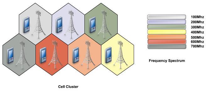
51 The information from sender to receiver is carried over a well defined frequency band. This is called a channel. Frequency Carries/Channels Each channel has a fixed frequency bandwidth (in KHz) and Capacity (bit-rate) Different frequency bands (channels) can be used to transmit information in parallel and independently. Replacing a single, high power transmitter (large cell) with many low power transmitters (small cells). Each providing coverage to only a small portion of the service area. Each base station is allocated a portion of the total number of channels available to the entire system, Nearby base stations are assigned different groups of channels. All the available channels are assigned to a relatively small number of neighboring base stations. 2-51
52 2-52
53 Assume a spectrum of 90KHz is allocated over a base frequency b for communication between stations A and B Assume each channel occupies 30KHz. There are 3 channels Each channel is simplex (Transmission occurs in one way) For full duplex communication: Use two different channels (front and reverse channels) Use time division in a channel Example Station A Channel 1 (b - b+30) Channel 2 (b+30 - b+60) Channel 3 (b+60 - b+90) Station B 2-53
54 2-54
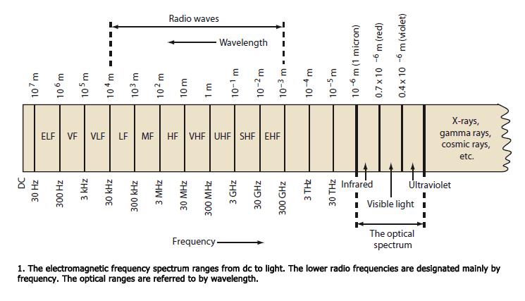
55 Frequencies for communication twisted pair coax cable optical transmission 1 Mm 300 Hz 10 km 30 khz 100 m 3 MHz 1 m 300 MHz 10 mm 30 GHz 100 m 3 THz 1 m 300 THz VLF LF MF HF VHF UHF SHF EHF infrared visible UV light VLF = Very Low Frequency LF = Low Frequency MF = Medium Frequency HF = High Frequency VHF = Very High Frequency Frequency and wave length: = c/f UHF = Ultra High Frequency SHF = Super High Frequency EHF = Extra High Frequency UV = Ultraviolet Light wave length, speed of light c 3x10 8 m/s, frequency f 2-55
56 2-56
57 2-57
58 Coverage Aspect of Next Generation Mobile Communication Systems Satellite In-Building Urban Suburban Global Picocell Microcell Macrocell Global 2-58
59 Cellular Geometries 2-59
60 Cellular Telephone Systems Provide connection to the PSTN for any user location within the radio range of the system. Characteristic Large number of users Large Geographic area Limited frequency spectrum Reuse of the radio frequency by the concept of cell. Basic cellular system: mobile stations, base stations, and mobile switching center. 60
61 FREQUENCY REUSE Each cellular base station is allocated a group of radio channels within a small geographic area called a cell. Neighboring cells are assigned different channel groups. By limiting the coverage area to within the boundary of the cell, the channel groups may be reused to cover different cells. Keep interference levels within tolerable limits. Frequency reuse or frequency planning The design process of selecting and allocating channel groups for all of the cellular base station within a system is FREQUENCY REUSE/PLANNING 2-61
62 Cell Cell is the small geographic area covered by the base station. The area around an antenna where a specific frequency range is used. Cell is represented graphically as a hexagonal shape, but in reality it is irregular in shape. cell 2-62
 Actual cell (c) Different cell models")
63 Cell Shape Cell R R R R R (a) Ideal cell (b) Actual cell (c) Different cell models 2-63

64 Cellular Geometries The most common model used for wireless networks is uniform hexagonal shape areas A base station with omni-directional antenna is placed in the middle of the cell d 3R 2-64
65 Fundamentals of Cellular Systems Ideal cell area (2-10 km radius) Cell BS MS Alternative shape of a cell MS Hexagonal cell area used in most models Illustration of a cell with a mobile station and a base station 2-65
66 Why hexagon for theoretical coverage? For a given distance between the center of a polygon and its farthest perimeter points, the hexagon has the largest area of the three Thus by using hexagon geometry, the fewest number of cells can cover a geographic region, and hexagon closely approximates a circular radiation pattern which would occur for an omnidirectional BS antenna and free space propagation When using hexagons to model a coverage areas, BS transmitters are depicted as either being in the center of the cell (center-excited cells) or on the three of the six cell vertices (edge-excited cells) Normally omnidirectional antennas are used in center-excited cells and directional antennas are used in corner-excited cells 2-66
67 Signal Strength Signal strength (in db) Cell i Cell j Select cell i on left of boundary Select cell j on right of boundary Ideal boundary 2-67
68 Frequency Reuse An efficient way of managing the radio spectrum is by reusing the same frequency, within the service area, as often as possible This frequency reuse is possible thanks to the propagation properties of radio waves 2-68

69 How Often Are Frequencies Reused (Frequency Reuse Factor)? Cells with the same number have the same set of frequencies Frequency Reuse 2-69
70 2-70
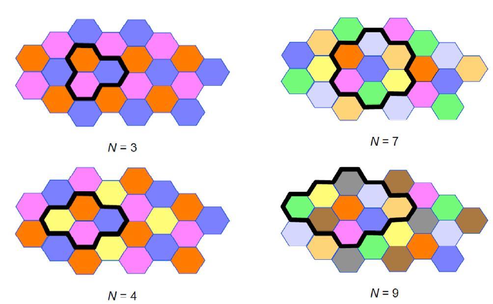
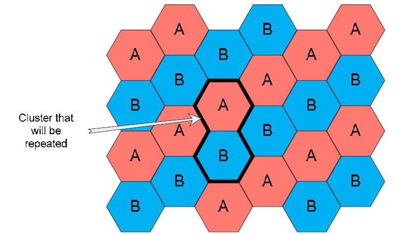
71 Cluster: A cluster is a group of adjacent cells. No frequency reuse is done within a cluster. Number of cells in cluster N=i 2 +ij+j cell cluster 4-cell cluster 7-cell cluster 2-71
72 2-72
73


74 2-74
75 Frequency Allocation Concepts Consider a cellular system which has a total of S duplex channels. Each cell is allocated a group of k channels,. k S The S channels are divided among N cells. The total number of available radio channels S kn The N cells which use the complete set of channels is called cluster. The cluster can be repeated M times within the system. The total number of channels, C, is used as a measure of capacity C MkN MS The capacity is directly proportional to the number of replication M. The cluster size, N, is typically equal to 4, 7, or 12. Small N is desirable to maximize capacity. The frequency reuse factor is given by 1/ N 2-75
76 Frequency Reuse The frequency reuse concept can be used in the time domain and the space domain. Frequency reuse in the time domain results in the occupation of the same frequency in different time slots. It is called time-division multiplexing (TDM). Frequency reuse in the space domain can be divided into two categories. 1. Same frequency assigned in two different geographic areas, such as AM or FM radio stations using the same frequency in different cities. 2. Same frequency repeatedly used in a same general area in one system2 the scheme is used in cellular systems. There are many cochannel cells in the system. The total frequency spectrum allocation is divided into K frequency reuse patterns, as illustrated in Fig. for K = 4, 7, 12, and 19. F6 F7 F2 F1 F5 F4 F3 F6 F7 F7 F2 F1 F5 F4 F2 F3 F6 F7 F1 F2 F3 F6 F1 F3 F5 F4 F5 F4 Fx: Set of frequency 7 cell reuse cluster 2-76
77 Hexagonal geometry has exactly six equidistance neighbors the lines joining the centers of any cell and each of its neighbors are separated by multiples of 60 degrees. Only certain cluster sizes and cell layout are possible. The number of cells per cluster, N, can only have values which satisfy N = 1, 3, 4, 7, 9, 12, 13, 16, 19, 21, 28,, etc. The popular value of N being 4 and 7. N i 2 ij where i and j are integers. j 2 j 60 o i 2-77
78 1 2 3 i j=2 j direction 60 i direction (a) Finding the center of an adjacent cluster using integers i and j (direction of i and j can be interchanged). j=1 j=1 i=2 i=2 j=1 i=2 i=2 j=1 j=1 i=2 i=2 j=1 (b) Formation of a cluster for N = 7 with i=2 and j=1 i=3 j=2 i=3 j=2 i=2 i=2 i=2 j=2 j=2 i=2 i=2 i=2 j=2 i=3 j=2 j=2 j=2 j=2 i=3 j=2 i=3 j=2 i=3 (c) A cluster with N =12 with i=2 and j=2 (d) A Cluster with N = 19 cells with i=3 and j=2 2-78
79 Reuse Distance R Cluster For hexagonal cells, the reuse distance is given by F7 F2 D 3NR F6 F1 F5 F4 F3 F6 F7 F2 F1 F3 where R is cell radius and N is the reuse pattern (the cluster size or the number of cells per cluster). Reuse factor is D q 3N R F5 F4 2-79
80 Frequency Reuse For hexagonal cells, the number of cells in the cluster is given by N N I 2 J 2 ( I J ), I, J 1,2,3,4... {1,3,4,7,9,12,16,19,21,...} D R 3N 2-80
81 Smaller N is greater capacity 2-81
82 D R 3N 2-82
83 Geometry of Hexagonal Cells (1) How to determine the DISTANCE between the nearest co-channel cells? Planning for Co-channel cells D is the distance to the center of the nearest co-channel cell R is the radius of a cell D j 3R i 30 o R 0 3R 2-83
84 where D = Distance between the cells using the same frequency, R = Center to vertex distance, N = Cluster size, q = Reuse frequency. 2-84
85 2-85
86 D 2 = 3 * R 2 * (i 2 + j 2 + i * j) As N = i 2 + j 2 + i * j D 2 = 3 * R 2 * N D 2 /R 2 = 3*N D/R = 3 N As q = D/R q = 3N 2-86
87 Co-channel cells for 7-cell reuse 2-87
88 Cochannel Interference Second tier cochannel Base Station First tier cochannel Base Station D 5 D 6 R D 4 D 2 D 1 Mobile Station D 3 Serving Base Station 2-88
89 2-89
90 Cochannel Interference Cochannel interference ratio is given by C I Carrier Interference M C k1 I k where I is co-channel interference and M is the maximum number of co-channel interfering cells. For M = 6, C/I is given by C I M k 1 C D k R g where g is the propagation path loss slope and g = 2~
91 Co-Channel Interference Consider only the first tier of interfering cells, if all interfering base stations are equidistant from the desired base station and if this distance is equal to the distance D between cell centers, then the above equation can be simplified to: (i.e., r=r and assume D i =D and use q=d/r): S I N I r i1 D i R N D I ( D / R) N I q N I 2-91
92 DESIRED C/I FROM A NORMAL CASE IN AN OMNIDIRECTIONAL ANTENNA SYSTEM Assume that all Dk are the same for simplicity, as shown in Fig; then D = Dk, and q = qk, and the value of C/I is based on the required system performance and the specified value of γ is based on the terrain environment. With given values of C/I and γ, the cochannel interference reduction factor q can be determined. Normal cellular practice is to specify C/I to be 18 db or higher based on subjective tests. this acceptance implies that both mobile radio multipath fading and cochannel interference become ineffective at that level. The path-loss slope γ is equal to about 4 in a mobile radio environment 1/4 q = D/R = (6 63.1) = 4.41 The 90th percentile of the total covered area would be achieved by increasing the transmitted power at each cell; increasing the same amount of transmitted power in each cell does not affect the result of Eq. (2.7-4). This is because q is not a function of transmitted power. The computer simulation described in the next section finds the value of q = 4.6, which is very close to Eq. The factor q can be related to the finite set of cells K in a hexagonal-shaped cellular system by 2-92
93 2-93
94 Example: Co-Channel Interference If S/I = 15 db required for satisfactory performance for forward channel performance of a cellular system. a) What is the Frequency Reuse Factor q (assume K=4)? b) Can we use K=3? Assume 6 co-channels all of them (same distance from the mobile), I.e. N=7 2-94
 N= 7 and =3 S I q N I 1 3 (4.583) 16.04 Or 12.05 db less than the minimum required level REJECT IT!")
95 Example: Co-Channel Interference a) NI =6 => cluster size N= 7, and when =4 The co-channel reuse ratio is q=d/r=sqrt(3n)=4.583 S I q N I 1 4 (4.583) Or db greater than the minimum required level ACCEPT IT!!! b) N= 7 and =3 S I q N I 1 3 (4.583) Or db less than the minimum required level REJECT IT!!!
96 Example: co-channel Interference We need a larger N (thus q is larger). Use eq. N =i 2 +ij+j 2, for i=j=2 next possible value is N=12. q=d/r=sqrt(3n) =6 and =3 S I q N I 1 3 (6) Or db N=12 can be used for minimum requirement, but it decreases the capacity (we already gave an example: when cluster size is smaller, the capacity is larger). 2-96
97 Worst Case Co-Channel Interference i.e., mobile terminal is located at the cell boundary where it receives the weakest signal from its own cell but is subjected to strong interference from all all the interfering cells. We need to modify our assumption, (we assumed D i =D). The S/I ratio can be expressed as S I S I N I r i1 D i 2( q 1) 2( D R) 4 1 2q R 2D 2( q 1) 4 Used D/R=q and =4. Where q=4.6 for normal seven cell reuse pattern. 2( D R) D D-R R D+R D+R D D-R 2-97
98 For hexagonal geometry with 7-cell cluster, with the mobile unit being at the cell boundary, the signal-to-interference ratio for the worst case can be approximated as ) ( 2) / ( 2) / ( ) 2( D R D R D R D R D R I S 2-98
99 Example: Worst Case Cochannel Interference A cellular system that requires an S/I ratio of 18dB. (a) if cluster size is 7, what is the worst-case S/I? (b) Is a frequency reuse factor of 7 acceptable in terms of co-channel interference? If not, what would be a better choice of frequency reuse ratio? Solution (a) N=7 q = 3N 4.6 S/I = 54.3 or 17.3 db. (b) The value of S/I is below the acceptable level of 18dB. We need to decrease I by increasing N =9. The S/I is or 19.8dB.. If a path loss component of =4, the worst-case signal-to-interference ratio is 2-99
100 Example: Worst Case Cochannel Interference For a conservative estimate if we use the shortest distance (=D-R) then S I 6( q 1 1) (3.6) 28 Or db. REMARK: In real situations, because of imperfect cell site locations and the rolling nature of the terrain configuration, the S/I ratio is often less than 17.3 db. It could be 14dB or lower which can occur in heavy traffic. Thus, the cellular system should be designed around the S/I ratio of the worst case. REMARK: If we consider the worst case for a 7-cell reuse pattern We conclude that a co-channel interference reduction factor of q=4.6 is not enough in an omnidirectional cell system. In an omnidirectional cell system N=9 (q=5.2) or N=12 (q=6.0) the cell reuse pattern would be a better choice. These cell reuse patterns would provide the S/I ratio of db and db, respectively
101 CAPACITY EXPANSION IN CELLULAR SYSTEM Techniques to provide more channels per coverage area is by Cell splitting Cell sectoring Coverage zone approches 2-101
102 CELL SPLITTING Cell splitting increases the capacity of cellular system since it increases the number of times the channel are reused Cell splitting - defining new cells which have smaller radius than orginal cells by installing these smaller cells called MICROCELLS between existing cells Capacity increases due to additional number of channels per unit area Cell splitting is process of subdividing a congested cell into smaller cells each with its own base station(with corresponding reduction in antenna height and tx power) 2-102
103 Cell Splitting Large cell (low density) Small cell (high density) Smaller cell (higher density) Depending on traffic patterns the smaller cells may be activated/deactivated in order to efficiently use cell resources
104 CELL SPLITTING Split congested cell into smaller cells. Preserve frequency reuse plan. Reduce transmission power. Reduce R to R/2 microcell 2-104
105 Transmission power reduction from to Pt1 P t 2 Examining the receiving power at the new and old cell boundary P Pr [at old cell boundary] Pt 1 r[ at new cell boundary] Pt 2 If we take n = 4 (path loss) and set the received power equal to each other P t2 The transmit power must be reduced by 12 db in order to fill in the original coverage area. Problem: if only part of the cells are splited Different cell sizes will exist simultaneously Handoff issues - high speed and low speed traffic can be simultaneously accommodated P t1 16 R n ( R / 2) n 2-105
106 CELL SPLITTING Splitting cells in each CELL Antenna downtiliting Illustration of cell splitting within a 3 km by 3 km square 2-106

107 Sectoring Decrease the co-channel interference and keep the cell radius R unchanged Replacing single omni-directional antenna by several directional antennas Radiating within a specified sector 2-107
108 Cell Sectoring by Antenna Design c 120 o b a b c 120 o a (a). Omni (b). 120 o sector (c). 120 o sector (alternate) c d 90 o a b e d f 60 o c a b (d). 90 o sector (e). 60 o sector 2-108
109 Cell Sectoring by Antenna Design Placing directional transmitters at corners where three adjacent cells meet B C X A 2-109
110 Microcell Zone Concept Antennas are placed at the outer edges of the cell Any channel may be assigned to any zone by the base station Mobile is served by the zone with the strongest signal. Handoff within a cell No channel re-assignment Switch the channel to a different zone site Reduce interference Low power transmitters are employed Microcell Micro cells can be introduced to alleviate capacity problems caused by hotspots. By clever channel assignment, the reuse factor is unchanged. As for cell splitting, there will occur interference problems when macro and micro cells must co-exist. Microcells-Reduced power, Good for city streets, along roads and inside large buildings 2-110
111 Terminology : Cellular traffic Trunking : Trunking is the concept that allows large number of users to use a smaller number of channels(or phone lines, customer service representatives, parking spots, public bathrooms, ) as efficiently as possible. Grade of service (GoS) : A user is allocated a channel on a per call basis. GoS is a measure of the ability of a user to access a trunked system during the busiest hour. It is typically given as the likelihood that a call is blocked (also known as blocking probability mentioned before). Trunking theory : is used to determine the number of channels required to service a certain offered traffic at a specific GoS. Call holding time (H) : the average duration of a call. Request rate (λ) : average number of call requests per-unit time
112 Trunking and Grade of Service Erlangs: One Erlangs represents the amount of traffic density carried by a channel that is completely occupied. Ex: A radio channel that is occupied for 30 minutes during an hour carries 0.5 Erlangs of traffic. Grade of Service (GOS): The likelihood that a call is blocked. Each user generates a traffic intensity of Erlangs given by H: average duration of a call. : average number of call requests per unit time A u A u H For a system containing U users and an unspecified number of channels, the total offered traffic intensity A, is given by A UA u For C channel trunking system, the traffic intensity, A is given as c Ac UAu / C 2-112

113 Traffic flow or intensity A Measured in Erlang, which is defined as the call minute per minute. Offered traffic for a single user is given as λ average number of call request H duration of a call A u = λ H For a system containing U user, total offered traffic A = U A u Exercise : There are 3000 calls per hour in a cell, each lasting an average of 1.76 min. Offered traffic A = (3000/60)(1.76) = 88 Erlangs If the offered traffic exceeds the maximum possible carried traffic, blocking occurs. There are two different strategies to be used. Blocked calls cleared Blocked calls delayed Trunking efficiency : is defined as the carried traffic intensity in Erlangs per channel, which is a value between zero and one. It is a function of the number of channels per cell and the specific GoS parameters
114 Capacity S = no of duplex channels available K = no of channel in one cell N = no of cell/cluster M = no of cluster in a given system C = total no of duplex channel available in a cellular system (capacity) C = M * K * N = M * S Example: For K = 100, N = 7, calculate system capacity for M = 6 and M = 4 i) C = 6 * 100 * 7 = 4200 channels ii) C = 4 * 100 * 7 = 2800 channels 2-114
115 Example 1 If total of 44 MHz of bandwidth is allocated to a particular FDD cellular radio system which uses two 25kHz simplex channels to provide full duplex voice and control channel, calculate the number of channels available per cell, k for (a) 3 cell reuse (b) 7 cell reuse (c) 12 cell reuse 2-115
116 Formula (Cellular Traffic) i) Total number of channel per cell (NC) NC = (Allocated spectrum) / (channel BW x Frequency reuse factor) unit = channel / cell ii) No.of cell in the service area = Total coverage area / area of the cell. Unit = cell Traffic intensity of each cell can be found from table or Erlang B chart. Depend on NC and GOS Traffic capacity = # of cell x traffic intensity /cell ( Erlang ) Iii) Total no.of user (U) = total traffic (A) / traffic per user ( A u ) Iv) number of call that can be made at any time = NC x no.of cell 2-116
117 Example 2 How many users can be supported for 0.5% blocking probability for the following number of trunked channels in a blocked calls cleared system. (a) 1 (b) 5 (c) 10 (d) 20 (e) 100 Assume each user generates 0.1 Erlangs of traffic 2-117
118 Example 3 A city has an area of 3000 sq.km and is covered by a cellular system using 7 cell per cluster. The area of a cell is 100 sq.km. The cellular system is allocated total bandwidth of 40 MHz of spectrum with full duplex channel bandwidth of 200 KHz. For the GOS of 2 % and the offered traffic per user is 0.03 Erlangs, calculate; a) The number of cell in the city b) The number of channels per cell c) Traffic intensity of each cell d) Traffic intensity for the city e) The total number of users that can be served in the city f) The number of mobiles per channel g) Number of call that can be made at any time in the city 2-118
119 Erlang B Trunking GOS 2-119

120 Erlang B 2-120

121 121 Thank you
Unit-1 The Cellular Concept
 Unit-1 The Cellular Concept 1.1 Introduction to Cellular Systems Solves the problem of spectral congestion and user capacity. Offer very high capacity in a limited spectrum without major technological
03_57_104_final.fm Page 97 Tuesday, December 4, :17 PM. Problems Problems
 03_57_104_final.fm Page 97 Tuesday, December 4, 2001 2:17 PM Problems 97 3.9 Problems 3.1 Prove that for a hexagonal geometry, the co-channel reuse ratio is given by Q = 3N, where N = i 2 + ij + j 2. Hint:
EKT 450 Mobile Communication System
 EKT 450 Mobile Communication System Chapter 6: The Cellular Concept Dr. Azremi Abdullah Al-Hadi School of Computer and Communication Engineering azremi@unimap.edu.my 1 Introduction Introduction to Cellular
UNIT-II 1. Explain the concept of frequency reuse channels. Answer:
 UNIT-II 1. Explain the concept of frequency reuse channels. Concept of Frequency Reuse Channels: A radio channel consists of a pair of frequencies one for each direction of transmission that is used for
ECE 476/ECE 501C/CS Wireless Communication Systems Winter Lecture 3: Cellular Fundamentals
 ECE 476/ECE 501C/CS 513 - Wireless Communication Systems Winter 2004 Lecture 3: Cellular Fundamentals Chapter 3 - The Cellular Concept - System Design Fundamentals I. Introduction Goals of a Cellular System
The Cellular Concept. History of Communication. Frequency Planning. Coverage & Capacity
 The Cellular Concept History of Communication Frequency Planning Coverage & Capacity Engr. Mian Shahzad Iqbal Lecturer Department of Telecommunication Engineering Before GSM: Mobile Telephony Mile stones
A Glimps at Cellular Mobile Radio Communications. Dr. Erhan A. İnce
 A Glimps at Cellular Mobile Radio Communications Dr. Erhan A. İnce 28.03.2012 CELLULAR Cellular refers to communications systems that divide a geographic region into sections, called cells. The purpose
Chapter 3: Cellular concept
 Chapter 3: Cellular concept Introduction to cellular concept: The cellular concept was a major breakthrough in solving the problem of spectral congestion and user capacity. It offered very high capacity
MOBILE COMMUNICATIONS (650520) Part 3
 Part 3") Philadelphia University Faculty of Engineering Communication and Electronics Engineering MOBILE COMMUNICATIONS (650520) Part 3 Dr. Omar R Daoud 1 Trunking and Grade Services Trunking: A means for providing
Philadelphia University Faculty of Engineering Communication and Electronics Engineering MOBILE COMMUNICATIONS (650520) Part 3 Dr. Omar R Daoud 1 Trunking and Grade Services Trunking: A means for providing
Vehicle Networks. Wireless communication basics. Univ.-Prof. Dr. Thomas Strang, Dipl.-Inform. Matthias Röckl
 Vehicle Networks Wireless communication basics Univ.-Prof. Dr. Thomas Strang, Dipl.-Inform. Matthias Röckl Outline Wireless Signal Propagation Electro-magnetic waves Signal impairments Attenuation Distortion
Antenna & Propagation. Basic Radio Wave Propagation
 For updated version, please click on http://ocw.ump.edu.my Antenna & Propagation Basic Radio Wave Propagation by Nor Hadzfizah Binti Mohd Radi Faculty of Electric & Electronics Engineering hadzfizah@ump.edu.my
Cellular Concept. Cell structure
 Cellular Concept Dr Yousef Dama Faculty of Engineering and Information Technology An-Najah National University 2014-2015 Mobile communications Lecture Notes, prepared by Dr Yousef Dama, An-Najah National
The Radio Channel. COS 463: Wireless Networks Lecture 14 Kyle Jamieson. [Parts adapted from I. Darwazeh, A. Goldsmith, T. Rappaport, P.
 The Radio Channel COS 463: Wireless Networks Lecture 14 Kyle Jamieson [Parts adapted from I. Darwazeh, A. Goldsmith, T. Rappaport, P. Steenkiste] Motivation The radio channel is what limits most radio
Wireless Communication Fundamentals Feb. 8, 2005
 Wireless Communication Fundamentals Feb. 8, 005 Dr. Chengzhi Li 1 Suggested Reading Chapter Wireless Communications by T. S. Rappaport, 001 (version ) Rayleigh Fading Channels in Mobile Digital Communication
Chapter 3. Mobile Radio Propagation
 Chapter 3 Mobile Radio Propagation Based on the slides of Dr. Dharma P. Agrawal, University of Cincinnati and Dr. Andrea Goldsmith, Stanford University Propagation Mechanisms Outline Radio Propagation
ECS 445: Mobile Communications The Cellular Concept
 Sirindhorn International Institute of Technology Thammasat University School of Information, Computer and Communication Technology ECS 445: Mobile Communications The Cellular Concept Prapun Suksompong,
ECE 476/ECE 501C/CS Wireless Communication Systems Winter Lecture 6: Fading
 ECE 476/ECE 501C/CS 513 - Wireless Communication Systems Winter 2005 Lecture 6: Fading Last lecture: Large scale propagation properties of wireless systems - slowly varying properties that depend primarily
ECE 476/ECE 501C/CS Wireless Communication Systems Winter Lecture 6: Fading
 ECE 476/ECE 501C/CS 513 - Wireless Communication Systems Winter 2003 Lecture 6: Fading Last lecture: Large scale propagation properties of wireless systems - slowly varying properties that depend primarily
ECE 476/ECE 501C/CS Wireless Communication Systems Winter Lecture 6: Fading
 ECE 476/ECE 501C/CS 513 - Wireless Communication Systems Winter 2004 Lecture 6: Fading Last lecture: Large scale propagation properties of wireless systems - slowly varying properties that depend primarily
UNIK4230: Mobile Communications Spring Per Hjalmar Lehne Tel:
 UNIK4230: Mobile Communications Spring 2015 Per Hjalmar Lehne per-hjalmar.lehne@telenor.com Tel: 916 94 909 Cells and Cellular Traffic (Chapter 4) Date: 12 March 2015 Agenda Introduction Hexagonal Cell
SNS COLLEGE OF ENGINEERING COIMBATORE DEPARTMENT OF INFORMATION TECHNOLOGY QUESTION BANK
 SNS COLLEGE OF ENGINEERING COIMBATORE 641107 DEPARTMENT OF INFORMATION TECHNOLOGY QUESTION BANK EC6801 WIRELESS COMMUNICATION UNIT-I WIRELESS CHANNELS PART-A 1. What is propagation model? 2. What are the
Data and Computer Communications
 Data and Computer Communications Chapter 14 Cellular Wireless Networks Eighth Edition by William Stallings Cellular Wireless Networks key technology for mobiles, wireless nets etc developed to increase
Data and Computer Communications. Tenth Edition by William Stallings
 Data and Computer Communications Tenth Edition by William Stallings Data and Computer Communications, Tenth Edition by William Stallings, (c) Pearson Education - 2013 CHAPTER 10 Cellular Wireless Network
Unit 4 - Cellular System Design, Capacity, Handoff, and Outage
 Unit 4 - Cellular System Design, Capacity, Handoff, and Outage Course outline How to access the portal Assignment. Overview of Cellular Evolution and Wireless Technologies Wireless Propagation and Cellular
Section 1 Wireless Transmission
 Part : Wireless Communication! section : Wireless Transmission! Section : Digital modulation! Section : Multiplexing/Medium Access Control (MAC) Section Wireless Transmission Intro. to Wireless Transmission
1. Classify the mobile radio transmission systems. Simplex & Duplex. 2. State example for a half duplex system. Push to talk and release to listen.
 1. Classify the mobile radio transmission systems. Simplex & Duplex. 2. State example for a half duplex system. Push to talk and release to listen. 3. State example for a Simplex system. Pager. 4. State
GTBIT ECE Department Wireless Communication
 Q-1 What is Simulcast Paging system? Ans-1 A Simulcast Paging system refers to a system where coverage is continuous over a geographic area serviced by more than one paging transmitter. In this type of
CHAPTER 2 WIRELESS CHANNEL
 CHAPTER 2 WIRELESS CHANNEL 2.1 INTRODUCTION In mobile radio channel there is certain fundamental limitation on the performance of wireless communication system. There are many obstructions between transmitter
UNIT Derive the fundamental equation for free space propagation?
 UNIT 8 1. Derive the fundamental equation for free space propagation? Fundamental Equation for Free Space Propagation Consider the transmitter power (P t ) radiated uniformly in all the directions (isotropic),
Communication Switching Techniques
 Communication Switching Techniques UNIT 5 P.M.Arun Kumar, Assistant Professor, Department of IT, Sri Krishna College of Engineering and Technology, Coimbatore. PRINCIPLES OF CELLULAR NETWORKS TOPICS TO
Chapter 1 Introduction to Mobile Computing (16 M)
") Chapter 1 Introduction to Mobile Computing (16 M) 1.1 Introduction to Mobile Computing- Mobile Computing Functions, Mobile Computing Devices, Mobile Computing Architecture, Evolution of Wireless Technology.
Chapter 1 Introduction to Mobile Computing (16 M) 1.1 Introduction to Mobile Computing- Mobile Computing Functions, Mobile Computing Devices, Mobile Computing Architecture, Evolution of Wireless Technology.
SEN366 (SEN374) (Introduction to) Computer Networks
 (Introduction to) Computer Networks") SEN366 (SEN374) (Introduction to) Computer Networks Prof. Dr. Hasan Hüseyin BALIK (8 th Week) Cellular Wireless Network 8.Outline Principles of Cellular Networks Cellular Network Generations LTE-Advanced
SEN366 (SEN374) (Introduction to) Computer Networks Prof. Dr. Hasan Hüseyin BALIK (8 th Week) Cellular Wireless Network 8.Outline Principles of Cellular Networks Cellular Network Generations LTE-Advanced
PROPAGATION MODELING 4C4
 PROPAGATION MODELING ledoyle@tcd.ie 4C4 http://ledoyle.wordpress.com/temp/ Classification Band Initials Frequency Range Characteristics Extremely low ELF < 300 Hz Infra low ILF 300 Hz - 3 khz Ground wave
Antennas & Propagation. CSG 250 Fall 2007 Rajmohan Rajaraman
 Antennas & Propagation CSG 250 Fall 2007 Rajmohan Rajaraman Introduction An antenna is an electrical conductor or system of conductors o Transmission - radiates electromagnetic energy into space o Reception
Chapter 3 Ahmad Bilal ahmadbilal.webs.com
 Chapter 3 A Quick Recap We learned about cell and reuse factor. We looked at traffic capacity We looked at different Earling Formulas We looked at channel strategies We had a look at Handoff Interference
EENG473 Mobile Communications Module 2 : Week # (8) The Cellular Concept System Design Fundamentals
 The Cellular Concept System Design Fundamentals") EENG473 Mobile Communications Module 2 : Week # (8) The Cellular Concept System Design Fundamentals Improving Capacity in Cellular Systems Cellular design techniques are needed to provide more channels
EENG473 Mobile Communications Module 2 : Week # (8) The Cellular Concept System Design Fundamentals Improving Capacity in Cellular Systems Cellular design techniques are needed to provide more channels
Mobile Radio Wave propagation channel- Path loss Models
 Mobile Radio Wave propagation channel- Path loss Models 3.1 Introduction The wireless Communication is one of the integral parts of society which has been a focal point for sharing information with different
E-716-A Mobile Communications Systems. Lecture #2 Basic Concepts of Wireless Transmission (p1) Instructor: Dr. Ahmad El-Banna
 Instructor: Dr. Ahmad El-Banna") October 2014 Ahmad El-Banna Integrated Technical Education Cluster At AlAmeeria E-716-A Mobile Communications Systems Lecture #2 Basic Concepts of Wireless Transmission (p1) Instructor: Dr. Ahmad El-Banna
October 2014 Ahmad El-Banna Integrated Technical Education Cluster At AlAmeeria E-716-A Mobile Communications Systems Lecture #2 Basic Concepts of Wireless Transmission (p1) Instructor: Dr. Ahmad El-Banna
UNIK4230: Mobile Communications. Abul Kaosher
 UNIK4230: Mobile Communications Abul Kaosher abul.kaosher@nsn.com Cells and Cellular Traffic Cells and Cellular Traffic Introduction Hexagonal Cell Geometry Co-Channel Interference (CCI) CCI Reduction
UNIK4230: Mobile Communications Spring 2013
 UNIK4230: Mobile Communications Spring 2013 Abul Kaosher abul.kaosher@nsn.com Mobile: 99 27 10 19 1 UNIK4230: Mobile Communications Cells and Cellular Traffic- I Date: 07.03.2013 2 UNIK4230: Mobile Communications
UNIT- 7. Frequencies above 30Mhz tend to travel in straight lines they are limited in their propagation by the curvature of the earth.
 UNIT- 7 Radio wave propagation and propagation models EM waves below 2Mhz tend to travel as ground waves, These wave tend to follow the curvature of the earth and lose strength rapidly as they travel away
Antennas and Propagation
 Antennas and Propagation Chapter 5 Introduction An antenna is an electrical conductor or system of conductors Transmission - radiates electromagnetic energy into space Reception - collects electromagnetic
Wireless Cellular Networks. Base Station - Mobile Network
 Wireless Cellular Networks introduction frequency reuse channel assignment strategies techniques to increase capacity handoff cellular standards 1 Base Station - Mobile Network RCC RVC FVC FCC Forward
Week 2. Topics in Wireless Systems EE584-F 03 9/9/2003. Copyright 2003 Stevens Institute of Technology - All rights reserved
 Week Topics in Wireless Systems 43 0 th Generation Wireless Systems Mobile Telephone Service Few, high-power, long-range basestations -> No sharing of spectrum -> few users -> expensive 44 Cellular Systems
Level 6 Graduate Diploma in Engineering Wireless and mobile communications
 9210-119 Level 6 Graduate Diploma in Engineering Wireless and mobile communications Sample Paper You should have the following for this examination one answer book non-programmable calculator pen, pencil,
EEG473 Mobile Communications Module 2 : Week # (6) The Cellular Concept System Design Fundamentals
 The Cellular Concept System Design Fundamentals") EEG473 Mobile Communications Module 2 : Week # (6) The Cellular Concept System Design Fundamentals Interference and System Capacity Interference is the major limiting factor in the performance of cellular
EEG473 Mobile Communications Module 2 : Week # (6) The Cellular Concept System Design Fundamentals Interference and System Capacity Interference is the major limiting factor in the performance of cellular
Cellular Wireless Networks and GSM Architecture. S.M. Riazul Islam, PhD
 Cellular Wireless Networks and GSM Architecture S.M. Riazul Islam, PhD Desirable Features More Capacity Less Power Larger Coverage Cellular Network Organization Multiple low power transmitters 100w or
ETI2511-WIRELESS COMMUNICATION II HANDOUT I 1.0 PRINCIPLES OF CELLULAR COMMUNICATION
 ETI2511-WIRELESS COMMUNICATION II HANDOUT I 1.0 PRINCIPLES OF CELLULAR COMMUNICATION 1.0 Introduction The substitution of a single high power Base Transmitter Stations (BTS) by several low BTSs to support
LECTURE 12. Deployment and Traffic Engineering
 1 LECTURE 12 Deployment and Traffic Engineering Cellular Concept 2 Proposed by Bell Labs in 1971 Geographic Service divided into smaller cells Neighboring cells do not use same set of frequencies to prevent
Chapter 1: Telecommunication Fundamentals
 Chapter 1: Telecommunication Fundamentals Block Diagram of a communication system Noise n(t) m(t) Information (base-band signal) Signal Processing Carrier Circuits s(t) Transmission Medium r(t) Signal
PRINCIPLES OF COMMUNICATION SYSTEMS. Lecture 1- Introduction Elements, Modulation, Demodulation, Frequency Spectrum
 PRINCIPLES OF COMMUNICATION SYSTEMS Lecture 1- Introduction Elements, Modulation, Demodulation, Frequency Spectrum Topic covered Introduction to subject Elements of Communication system Modulation General
Chapter 2: Wireless Transmission. Mobile Communications. Spread spectrum. Multiplexing. Modulation. Frequencies. Antenna. Signals
 Mobile Communications Chapter 2: Wireless Transmission Frequencies Multiplexing Signals Spread spectrum Antenna Modulation Signal propagation Cellular systems Prof. Dr.-Ing. Jochen Schiller, http://www.jochenschiller.de/
INTRODUCTION TO COMMUNICATION SYSTEMS AND TRANSMISSION MEDIA
 COMM.ENG INTRODUCTION TO COMMUNICATION SYSTEMS AND TRANSMISSION MEDIA 9/9/2017 LECTURES 1 Objectives To give a background on Communication system components and channels (media) A distinction between analogue
2.4 OPERATION OF CELLULAR SYSTEMS
 INTRODUCTION TO CELLULAR SYSTEMS 41 a no-traffic spot in a city. In this case, no automotive ignition noise is involved, and no cochannel operation is in the proximity of the idle-channel receiver. We
Session2 Antennas and Propagation
 Wireless Communication Presented by Dr. Mahmoud Daneshvar Session2 Antennas and Propagation 1. Introduction Types of Anttenas Free space Propagation 2. Propagation modes 3. Transmission Problems 4. Fading
Chapter 5 The Cellular Concept
 hapter 5 The ellular oncept 1 ell Shape Actual cell/ideal cell Signal Strength Handoff egion ell apacity Traffic theory Erlang B and Erlang ell Structure Frequency euse euse Distance ochannel Interference
Antennas and Propagation. Chapter 5
 Antennas and Propagation Chapter 5 Introduction An antenna is an electrical conductor or system of conductors Transmission - radiates electromagnetic energy into space Reception - collects electromagnetic
Data and Computer Communications Chapter 4 Transmission Media
 Data and Computer Communications Chapter 4 Transmission Media Ninth Edition by William Stallings Data and Computer Communications, Ninth Edition by William Stallings, (c) Pearson Education - Prentice Hall,
Data and Computer Communications. Chapter 10 Cellular Wireless Networks
 Data and Computer Communications Chapter 10 Cellular Wireless Networks Cellular Wireless Networks 5 PSTN Switch Mobile Telecomm Switching Office (MTSO) 3 4 2 1 Base Station 0 2016-08-30 2 Cellular Wireless
Unguided Media and Matched Filter After this lecture, you will be able to Example?
 Unguided Media and Matched Filter After this lecture, you will be able to describe the physical and transmission characteristics of various unguided media Example? B.1 Unguided media Guided to unguided
Introduction to Wireless and Mobile Networking. Hung-Yu Wei g National Taiwan University
 Introduction to Wireless and Mobile Networking Lecture 3: Multiplexing, Multiple Access, and Frequency Reuse Hung-Yu Wei g National Taiwan University Multiplexing/Multiple Access Multiplexing Multiplexing
LECTURE 3. Radio Propagation
 LECTURE 3 Radio Propagation 2 Simplified model of a digital communication system Source Source Encoder Channel Encoder Modulator Radio Channel Destination Source Decoder Channel Decoder Demod -ulator Components
EENG473 Mobile Communications Module 2 : Week # (4) The Cellular Concept System Design Fundamentals
 The Cellular Concept System Design Fundamentals") EENG473 Mobile Communications Module 2 : Week # (4) The Cellular Concept System Design Fundamentals Frequency reuse or frequency planning : The design process of selecting and allocating channel groups
EENG473 Mobile Communications Module 2 : Week # (4) The Cellular Concept System Design Fundamentals Frequency reuse or frequency planning : The design process of selecting and allocating channel groups
King Fahd University of Petroleum & Minerals Computer Engineering Dept
 King Fahd University of Petroleum & Minerals Computer Engineering Dept COE 543 Mobile and Wireless Networks Term 0 Dr. Ashraf S. Hasan Mahmoud Rm -148-3 Ext. 174 Email: ashraf@ccse.kfupm.edu.sa 4//003
Ch3. The Cellular Concept Systems Design Fundamentals. From Rappaport s book
 Ch3. The Cellular Concept Systems Design Fundamentals. From Rappaport s book Instructor: Mohammed Taha O. El Astal LOGO Early mobile systems The objective was to achieve a large coverage area by using
UNIT- 3. Introduction. The cellular advantage. Cellular hierarchy
 UNIT- 3 Introduction Capacity expansion techniques include the splitting or sectoring of cells and the overlay of smaller cell clusters over larger clusters as demand and technology increases. The cellular
Wireless Transmission Rab Nawaz Jadoon
 Wireless Transmission Rab Nawaz Jadoon DCS Assistant Professor COMSATS IIT, Abbottabad Pakistan COMSATS Institute of Information Technology Mobile Communication Frequency Spectrum Note: The figure shows
Mobile Wireless Communications - Overview
 S. R. Zinka srinivasa_zinka@daiict.ac.in October 16, 2014 First of all... Which frequencies we can use for wireless communications? Atmospheric Attenuation of EM Waves 100 % Gamma rays, X-rays and ultraviolet
ECE6604 PERSONAL & MOBILE COMMUNICATIONS
 ECE6604 PERSONAL & MOBILE COMMUNICATIONS GORDON L. STÜBER School of Electrical and Computer Engineering Georgia Institute of Technology Atlanta, Georgia, 30332-0250 Ph: (404) 894-2923 Fax: (404) 894-7883
CHAPTER 19 CELLULAR TELEPHONE CONCEPTS # DEFINITION TERMS
 CHAPTER 19 CELLULAR TELEPHONE CONCEPTS # DEFINITION TERMS 1) The term for mobile telephone services which began in 1940s and are sometimes called Manual telephone systems. Mobile Telephone Manual System
Reti di Telecomunicazione. Channels and Multiplexing
 Reti di Telecomunicazione Channels and Multiplexing Point-to-point Channels They are permanent connections between a sender and a receiver The receiver can be designed and optimized based on the (only)
M Y R E V E A L - C E L L U L A R
 M Y R E V E A L - C E L L U L A R The hexagon cell shape If we have two BTSs with omniantennas and we require that the border between the coverage area of each BTS is the set of points where the signal
Wireless Communication Technologies (16:332:546)
") Wireless Communication Technologies (16:332:546) Taught by Professor Narayan Mandayam Lecture 7 : Co-Channel Interference Slides prepared by : Shuangyu Luo Outline Co-channel interference 4 Examples of
Wireless Communication Technologies (16:332:546) Taught by Professor Narayan Mandayam Lecture 7 : Co-Channel Interference Slides prepared by : Shuangyu Luo Outline Co-channel interference 4 Examples of
CHAPTER 2. Instructor: Mr. Abhijit Parmar Course: Mobile Computing and Wireless Communication ( )
") CHAPTER 2 Instructor: Mr. Abhijit Parmar Course: Mobile Computing and Wireless Communication (2170710) Syllabus Chapter-2.1 Cellular Wireless Networks 2.1.1 Principles of Cellular Networks Underlying technology
CHAPTER 2 Instructor: Mr. Abhijit Parmar Course: Mobile Computing and Wireless Communication (2170710) Syllabus Chapter-2.1 Cellular Wireless Networks 2.1.1 Principles of Cellular Networks Underlying technology
CS441 Mobile & Wireless Computing Communication Basics
 Department of Computer Science Southern Illinois University Carbondale CS441 Mobile & Wireless Computing Communication Basics Dr. Kemal Akkaya E-mail: kemal@cs.siu.edu Kemal Akkaya Mobile & Wireless Computing
Antennas and Propagation. Chapter 5
 Antennas and Propagation Chapter 5 Introduction An antenna is an electrical conductor or system of conductors Transmission - radiates electromagnetic energy into space Reception - collects electromagnetic
Cellular Wireless Networks. Chapter 10
 Cellular Wireless Networks Chapter 10 Cellular Network Organization Use multiple low-power transmitters (100 W or less) Areas divided into cells Each cell is served by base station consisting of transmitter,
Antennas and Propagation
 Mobile Networks Module D-1 Antennas and Propagation 1. Introduction 2. Propagation modes 3. Line-of-sight transmission 4. Fading Slides adapted from Stallings, Wireless Communications & Networks, Second
Lecture 2: The Concept of Cellular Systems
 Radiation Patterns of Simple Antennas Isotropic Antenna: the isotropic antenna is the simplest antenna possible. It is only a theoretical antenna and cannot be realized in reality because it is a sphere
Contents. ITS323: Introduction to Data Communications CSS331: Fundamentals of Data Communications. Transmission Media and Spectrum.
 2 ITS323: Introduction to Data Communications CSS331: Fundamentals of Data Communications Sirindhorn International Institute of Technology Thammasat University Prepared by Steven Gordon on 3 August 2015
ITS323: Introduction to Data Communications CSS331: Fundamentals of Data Communications
 ITS323: Introduction to Data Communications CSS331: Fundamentals of Data Communications Sirindhorn International Institute of Technology Thammasat University Prepared by Steven Gordon on 3 August 2015
Wireless WANS and MANS. Chapter 3
 Wireless WANS and MANS Chapter 3 Cellular Network Concept Use multiple low-power transmitters (100 W or less) Areas divided into cells Each served by its own antenna Served by base station consisting of
Revision of Lecture One
 Revision of Lecture One System block Transceiver Wireless Channel Signal / System: Bandpass (Passband) Baseband Baseband complex envelope Linear system: complex (baseband) channel impulse response Channel:
Structure of the Lecture
 Structure of the Lecture Chapter 2 Technical Basics: Layer 1 Methods for Medium Access: Layer 2 Representation of digital signals on an analogous medium Signal propagation Characteristics of antennas Chapter
Chapter 14. Cellular Wireless Networks
 Chapter 14 Cellular Wireless Networks Evolu&on of Wireless Communica&ons 1901 Marconi: Trans-Atlantic wireless transmission 1906 Fessenden: first radio broadcast (AM) 1921 Detroit Police Dept wireless
ECE 5325/6325: Wireless Communication Systems Lecture Notes, Spring 2013
 ECE 5325/6325: Wireless Communication Systems Lecture Notes, Spring 2013 Lecture 1 Today: (1) Syllabus, (2) Cellular Systems Intro, (3) Power and Path Loss Readings: Molisch Chapters 1, 2. For Thursday:
Figure 1.1:- Representation of a transmitter s Cell
 Volume 4, Issue 2, February 2014 ISSN: 2277 128X International Journal of Advanced Research in Computer Science and Software Engineering Research Paper Available online at: www.ijarcsse.com Study on Improving
RRC Vehicular Communications Part II Radio Channel Characterisation
 RRC Vehicular Communications Part II Radio Channel Characterisation Roberto Verdone Slides are provided as supporting tool, they are not a textbook! Outline 1. Fundamentals of Radio Propagation 2. Large
LESSON PLAN. LP-EC1451 LP Rev. No: 02 Sub Code & Name : EC1451 MOBILE COMMUNICATIONS Date: 05/12/2009. Unit: I Branch: EC Semester: VIII Page 01 of 06
 Unit: I Branch: EC Semester: VIII Page 01 of 06 Unit I Syllabus: Cellular Concept and System Design Fundamentals: Introduction to wireless communication: Evolution of mobile communications, mobile radio
Antennas and Propagation
 CMPE 477 Wireless and Mobile Networks Lecture 3: Antennas and Propagation Antennas Propagation Modes Line of Sight Transmission Fading in the Mobile Environment Introduction An antenna is an electrical
2018/5/23. YU Xiangyu
 2018/5/23 YU Xiangyu yuxy@scut.edu.cn Structure of Mobile Communication System Cell Handover/Handoff Roaming Mobile Telephone Switching Office Public Switched Telephone Network Tomasi Advanced Electronic
ECE 5325/6325: Wireless Communication Systems Lecture Notes, Spring 2010
 ECE 5325/6325: Wireless Communication Systems Lecture Notes, Spring 2010 Lecture 2 Today: (1) Frequency Reuse, (2) Handoff Reading for today s lecture: 3.2-3.5 Reading for next lecture: Rap 3.6 HW 1 will
William Stallings Data and Computer Communications 7 th Edition. Chapter 4 Transmission Media
 William Stallings Data and Computer Communications 7 th Edition Chapter 4 Transmission Media Overview Guided - wire Unguided - wireless Characteristics and quality determined by medium and signal For guided,
Unit 3 - Wireless Propagation and Cellular Concepts
 X Courses» Introduction to Wireless and Cellular Communications Unit 3 - Wireless Propagation and Cellular Concepts Course outline How to access the portal Assignment 2. Overview of Cellular Evolution
GSM FREQUENCY PLANNING
 GSM FREQUENCY PLANNING PROJECT NUMBER: PRJ070 BY NAME: MUTONGA JACKSON WAMBUA REG NO.: F17/2098/2004 SUPERVISOR: DR. CYRUS WEKESA EXAMINER: DR. MAURICE MANG OLI Introduction GSM is a cellular mobile network
UNDER STANDING RADIO FREQUENCY Badger Meter, Inc.
 UNDER STANDING RADIO FREQUENCY UNDERSTANDING RADIO FREQUENCY Regional Sales Meeting March 1-2, 2011 Brian Fiut Sr. Product Manager Itron Inc. Liberty Lake, WA August 25, 2010 RADIO PROPAGATION Radio consists
Revision of Lecture One
 Revision of Lecture One System blocks and basic concepts Multiple access, MIMO, space-time Transceiver Wireless Channel Signal/System: Bandpass (Passband) Baseband Baseband complex envelope Linear system:
Direct Link Communication II: Wireless Media. Motivation
 Direct Link Communication II: Wireless Media Motivation WLAN explosion cellular telephony: 3G/4G cellular providers/telcos in the mix self-organization by citizens for local access large-scale hot spots:
Radio Propagation Fundamentals
 Radio Propagation Fundamentals Concept of Electromagnetic Wave Propagation Mechanisms Modes of Propagation Propagation Models Path Profiles Link Budget Fading Channels Electromagnetic (EM) Waves EM Wave
Redline Communications Inc. Combining Fixed and Mobile WiMAX Networks Supporting the Advanced Communication Services of Tomorrow.
 Redline Communications Inc. Combining Fixed and Mobile WiMAX Networks Supporting the Advanced Communication Services of Tomorrow WiMAX Whitepaper Author: Frank Rayal, Redline Communications Inc. Redline