Structure of the Lecture
|
|
|
- Kelly Gibson
- 5 years ago
- Views:
Transcription
1 Structure of the Lecture Chapter 2 Technical Basics: Layer 1 Methods for Medium Access: Layer 2 Representation of digital signals on an analogous medium Signal propagation Characteristics of antennas Chapter 3 Wireless Networks: Bluetooth, WLAN, WirelessMAN, WirelessWAN Mobile Networks: GSM, GPRS, UMTS Satellites and Broadcast Networks Chapter 4 Mobility on the network layer: Mobile IP, Routing, Ad-Hoc Networks Mobility on the transport layer: reliable transmission, flow control, QoS Mobility support on the application layer Page 1
2 Radio Waves Data are represented physically as electromagnetic waves: s(t) = A sin(2 π f t + ϕ) A A: Amplitude f: Frequency (T: Duration of an oscillation) ϕ: Phase ϕ 0 T = 1/f Twisted Pair Coaxial Cable Wave Guide Optical transmission Wavelength Frequency Infrared Visible light Relation between frequency and wavelength:: λ = c/f with wavelength λ, speed of light c 3x10 8 m/s, frequency f Page 2
3 Frequencies for Mobile Communication Twisted Pair Coaxial Cable Wave Guide Optical transmission Wavelength Frequency VHF-/UHF-ranges for mobile radio Simple, small antenna for cars Deterministic propagation characteristics, reliable connections SHF and higher for directed radio links, satellite communication Small antenna, focusing Large bandwidth available Wireless LANs use frequencies in UHF to SHF spectrum Some systems planned up to EHF Limitations due to absorption by water and oxygen molecules (resonance frequencies), leading to weather dependent fading, signal loss caused by heavy rainfall etc. Infrared Visible light Page 3
4 Frequencies (MHz) and Regulations ITU-R holds auctions for new frequencies, manages frequency bands worldwide (WRC, World Radio Conferences) Europe USA Japan Cellular Phones Cordless Phones Wireless LANs GSM , / , , / , / UMTS (FDD) , UMTS (TDD) , CT , CT DECT IEEE HIPERLAN , AMPS, TDMA, CDMA , TDMA, CDMA, GSM , PACS , PACS-UB IEEE , PDC , , , PHS JCT IEEE Page 4
5 Signals Classification of signals regarding their characteristics: continuous time/discrete time continuous values/discrete values analog signal = continuous time and continuous values digital signal = discrete time and discrete values Different representations of a signal: Amplitude spectrum (amplitude over time) Frequency spectrum (amplitude or phase over frequency) Phase state diagram (amplitude A and phase ϕ in polar coordinates) A [V] A [V] Q = A sin ϕ (Quadrature) t[s] ϕ ϕ f [Hz] I = A cos ϕ (In-phase) Page 5
6 Modulation For transmission, a modulation of the discrete time and value signal on an analogous carrier frequency The carrier is a periodical sinus signal on a certain frequency: s(t) = A sin(2 π f t + ϕ) X un-modulated signal carrier frequency (sin) modulated signal Modulation in two steps: analogous base-band digital signal data digital analogous modulation modulation Sender carrier frequency Page 6
7 Modulation of Digital Signals value time Digital modulation is possible in several ways, basing on the parameters of an analogous wave: s(t) = A sin(2 π f t + ϕ) Amplitude Frequency Phase Amplitude Shift Keying (ASK) Easy to realize Needs not much bandwidth Susceptible against disturbance (weakening of signal strength over distance) Often used within optical systems Page 7
8 Bandwidth Each periodic signal can be represented by a composition of harmonic signals (Fourier-Transformation): g( t) = 1 2 c + n= 1 a n sin(2πnft) + n= 1 b n cos(2πnft) ideal periodical signal t real composition (based on harmonics) t An analog signal produced by digital modulation can also be seen as a periodic signal - that influences the transmission! Page 8
9 Needed Bandwidth Nyquist: theoretical minimum bandwidth B required for transmitting S symbols per second is given by S/2 Hz Bandwidth: Width of the frequency range necessary for transmission of a given number of symbols. Not (as usually spoken about) an amount of data! Capacity: from a given bandwidth one can compute the maximum possible data rate achievable on the frequency range (by considering the number of possible symbols and the number of bits which can be coded per symbol) That means: we never can transmit data on only one single frequency, we always need a certain frequency range for transmission! The higher the capacity of a transmission channel has to be, the more bandwidth is needed! Page 9

10 Bandwidth in Radio Communication Now encode your information on a carrier frequency f T, here using ASK: Forurier transform now tells you: the signal is not longer propagating as a single frequency f T, but is a burst of frequencies Resulting frequency spectrum: It is not only transmitted on the carrier frequency, but we also spread into the neighbored frequency ranges (where f B is the bandwidth of the data signal, i.e. the maximum frequency which with the amplitude level is changing): That means: depending on a signal s bandwidth the needed communication channel bandwidth can be computed. Page 10
 Amplitude Frequency Phase Waste of frequencies Needs high bandwidth Used in data transmission using phone lines (modems) Resulting signal (frequency domain): Page")
11 Modulation of Digital Signals value time Digital modulation is possible in several ways, basing on the parameters of an analogous wave: s(t) = A sin(2 π f t + ϕ) Frequency Shift Keying (FSK) Amplitude Frequency Phase Waste of frequencies Needs high bandwidth Used in data transmission using phone lines (modems) Resulting signal (frequency domain): Page 11
 Amplitude Frequency Phase 180 phase shift Complex demodulation Robust against disturbances Often used in mobile transmissions Resulting signal (frequency domain): Page 12")
12 Modulation of Digital Signals value time Digital modulation is possible in several ways, basing on the parameters of an analogous wave: s(t) = A sin(2 π f t + ϕ) Phase Shift Keying (PSK) Amplitude Frequency Phase 180 phase shift Complex demodulation Robust against disturbances Often used in mobile transmissions Resulting signal (frequency domain): Page 12
13 Minimum Shift Keying (MSK) Enhancement of FSK Increases bandwidth efficiency (transmission rate / needed bandwidth) and reduces disturbances of neighbored frequencies FSK: bandwidth depends on the distance between the carrier frequencies Special pre-computation reduces the distance: Minimum Shift Keying Bits are separated into even and odd bits, the duration of a bit is doubled Depending on the bit values (even, odd) the higher or the lower carrier frequency, original or inverted, is chosen The frequency of one carrier is twice the frequency of the other Even higher bandwidth efficiency using a Gaussian low-pass filter (i.e. restrict the needed frequency range by cutting away high frequencies) GMSK (Gaussian MSK), e.g. used in GSM and DECT Page 13
14 Minimum Shift Keying (MSK) data even bits odd bits Bit even odd Signal h l l h value f 1 f 2 lower frequency higher frequency h: high frequency l: low frequency +: original signal -: inverted signal MSK signal t No phase shifts! Page 14
15 Advanced Phase Shift Keying Shifting is not restricted to two phases: it can be done between M phases, with the only requirement for M is to be power to 2. This allows to transmit several bits in parallel. Example: QPSK (Quaternary Phase Shift Keying) Shifting between 4 phases 4 phase allow for 4 states: code 2 bits at once Thus: doubling transmission rate Q = A sinϕ ϕ I = A cosϕ A = Amplitude of the signal I = In-Phase, signal component (in phase with carrier signal) Q = Quadrature-Phase, quadrature component (vertically to phase of carrier) Page 15
16 Advanced Phase Shift Keying Quadrature Amplitude Modulation (QAM) Combination of ASK and QPSK n bit can be coded at once (n=2 is the simple QPSK) Bit error rate increases with increasing n, but less than if we would only use PSK with higher number of phases QAM: 4 bit per signal: 0011 and 0001 are in phase, but have different amplitudes 0000 und 0010 have same amplitude, but different phases Today: in use are methods like 256-QAM Page 16
17 Antennas Antennas are converting electrical signals into electromagnetic waves (and vice versa) Passive device, i.e. power of radiated signal is not higher than the power of the transmitter Principle: oscillatory circuit oscillating electrical field saved in a condenser, and magnetic field induced in a coil Modified circuit produces an oscillating electrical and magnetic field when feeding power in it (resp. Converts incoming fields into output power) Antennas are giving a gain i.e. larger antennas are producing signals of larger power and are more sensible for receiving weak signals. Thus, better antennas can increase the signal quality and by this the range of a signal Page 17
18 Antennas: isotropic Radiator Isotropic radiator: equal radiation in all directions (three dimensional) - only a theoretical reference antenna Real antennas always have directive effects (vertically and/or horizontally) Radiation pattern: measurement of radiation around an antenna y z z x y x ideal isotropic radiator Page 18
19 Antennas: simple Dipoles Real antennas are not isotropic radiators but, e.g., dipoles with lengths λ/4 on car roofs or λ/2 as Hertzian dipole shape of antenna proportional to wavelength λ/4 λ/2 Example: Radiation pattern of a simple Hertzian dipole y y z x z x Simple dipole side view (xy-plane) side view (yz-plane) top view (xz-plane) Gain: maximum power in the direction of the main lobe compared to the power of an isotropic radiator (with the same average power) Page 19
20 Antennas: directed and sectorized Often used for microwave connections or base stations for mobile phones (e.g., radio coverage of a valley) y y z x z x directed antenna side view (xy-plane) side view (yz-plane) top view (xz-plane) z z x x sectorized antenna top view, 3 sectors top view, 6 sectors New trend: beamforming antennas depending on the location of a station which should be served, the antenna can focus its radiation to this station Page 20

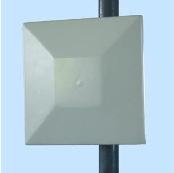
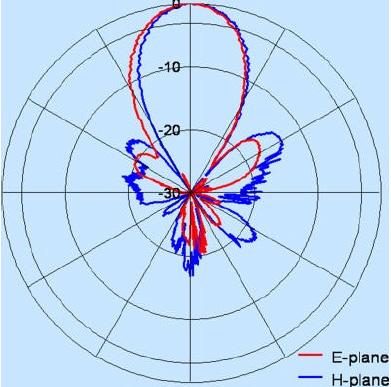
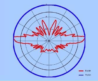
21 In Reality Page 21
22 Antennas: Diversity Grouping of two or more antennas to improve signal quality or transmission capacity We need multi-element antenna arrays Antenna diversity Switched diversity, selection diversity Receiver chooses antenna with highest output power Diversity combining Combine output power to produce gain Co-phasing needed to avoid cancellation (signal is received with different phases) λ/4 λ/2 λ/4 λ/2 λ/2 λ/2 + + ground plane Page 22
23 Signal Propagation Propagation in free space always in straight line Signal power decreases with increasing distance Basic relation: λ P = P G G r t 4π d r t with P r = received signal power P t = transmitted signal power G r = gain of receiver antenna G t = gain of transmitter antenna λ = wave length of carrier frequency d = distance between transmitter and receiver The quality of a received signal not only depends on the signal strength on sender side, but also on the used antennas, and on the carrier frequency Bad luck: the higher the carrier frequency, the lower the wave length and by this also the received power decreases faster with ongoing distance Page 23
24 Signal Propagation Depending on the received signal power, three regions can be identified: Transmission range Communication possible Low error rate Detection range Detection of the signal possible No communication possible (error rate) Interference range Signal may not be detected Signal adds to the background noise Interference Detection Transmission Sender distance In reality: received power is proportional to sending power by 1/d α (d = distance between sender and receiver, α = 2 in free space, in a city, 4-6 indoor) Values for α larger than 2 result from influences of the environment causing attenuation, reflection, scattering, Page 24
25 Influence of the Atmosphere 400 km Ionosphere Ionosphere Electrical loaded ions enable a propagation of radio waves over long distances 50 km 6-18 km 0 km Stratosphere Troposphere Earth Surface Stratosphere Constant temperature and steam; not much influence on radio waves Troposphere variable expansion (6 km at the poles, 18 km at the equator) Weather changes can influence the signal propagation Page 25
26 Frequency and Propagation A ground wave" propagates along earth s surface Propagation over the horizon (1000 km) A diffraction is caused by obstacles Only frequencies up to 2 MHz Diffraction of waves at the ionosphere (depending on the frequency, the ion density, and the angle of incidence) The higher the frequency, the lower the diffraction Propagation over 100 km, only frequencies up to ca. 100 MHz In mobile telecommunication networks and Wireless LANs: Higher frequencies, not influenced by earth s surface or ionosphere Receiving only possible in line of sight, but by obstacles, not only an attenuation Chapter is possible, 2.1: Layer but 1sometimes also an increasing of the range! Page 26
27 Propagation in Natural/Human Environments Factors influencing the propagation: Natural environment: mountains, water, vegetation, rain, snow Artificial environment: buildings, cars, etc. Propagation: Attenuation, shading (rain, vegetation) Diffraction at edges Reflection at large planes Scattering at small obstacles Refraction: refraction index gets smaller with increasing height diffraction attenuation line of sight scattering reflection Antenna diversity: multi-path propagation maybe can improve signal quality! Page 27
28 Multipath Propagation Signal can take many different paths between sender and receiver due to reflection, scattering, diffraction, : signal at sender signal at receiver The signal is dispersed over time (time dispersion) Interference with neighbored signals, Inter-Symbol-Interference Attenuation of the signal due to reflection, diffraction, A signal reaches the receiver directly and phase shifted! depending on the phase of the different received signal parts, destructive interference is possible, in the worst case erase the signal completely Page 28

29 Real World Examples Page 29
30 Effects of Mobility Channel characteristics change over time and location Signal paths change Different delay variations of different signal parts Different phases of signal parts Quick changes in the power received (short term fading) Additional changes in Distance to sender Obstacles further away long term fading Slow changes in the average power received (long term fading) short term fading Page 30
31 Further Problems Reason Multipath Propagation Movement Attenuation Shading Effect Fast Fading Delay spread (Time dispersion) Doppler effect (Frequency dispersion) Path loss Slow Fading Meaning Highly fluctuating signal strength depending on the distance Received signal consists of several components with short temporal differences The phase of the received signal is changed basing on the current distance between sender and receiver Rain/fog are changing the propagation of a signal depending on its frequency Slow fluctuation of the average signal strength Page 31
32 Conclusion Important task on layer 1: modulation of digital data to analogous radio waves ASK, FSK, PSK PSK often is preferred in mobile communications To achieve higher data rates: QPSK, QAM Problems with signal propagation Attenuation of signal by the environment Multipath propagation leads to disturbances of received signals (but also can help to reach places which are not in straight line-of-sight of the transmitter) We have to live with the effects of mobility layer 2 has to deal with the problems Page 32
Structure of the Lecture. Radio Waves. Frequencies for Mobile Communication. Frequencies (MHz) and Regulations
 and Regulations") Structure of the Lecture Chapter 2 Technical Basics: Laer Methods for Medium Access: Laer 2 Representation of digital signals on an analogous medium Signal propagation Characteristics of antennas Chapter
Structure of the Lecture Chapter 2 Technical Basics: Laer Methods for Medium Access: Laer 2 Representation of digital signals on an analogous medium Signal propagation Characteristics of antennas Chapter
Chapter 2: Wireless Transmission. Mobile Communications. Spread spectrum. Multiplexing. Modulation. Frequencies. Antenna. Signals
 Mobile Communications Chapter 2: Wireless Transmission Frequencies Multiplexing Signals Spread spectrum Antenna Modulation Signal propagation Cellular systems Prof. Dr.-Ing. Jochen Schiller, http://www.jochenschiller.de/
E-716-A Mobile Communications Systems. Lecture #2 Basic Concepts of Wireless Transmission (p1) Instructor: Dr. Ahmad El-Banna
 Instructor: Dr. Ahmad El-Banna") October 2014 Ahmad El-Banna Integrated Technical Education Cluster At AlAmeeria E-716-A Mobile Communications Systems Lecture #2 Basic Concepts of Wireless Transmission (p1) Instructor: Dr. Ahmad El-Banna
October 2014 Ahmad El-Banna Integrated Technical Education Cluster At AlAmeeria E-716-A Mobile Communications Systems Lecture #2 Basic Concepts of Wireless Transmission (p1) Instructor: Dr. Ahmad El-Banna
Wireless Networks. Why Wireless Networks? Wireless Local Area Network. Wireless Personal Area Network (WPAN)
") Wireless Networks Why Wireless Networks? rate MBit/s 100.0 10.0 1.0 0.1 0.01 wired terminals WMAN WLAN CORDLESS (CT, DECT) Office Building stationary walking drive Indoor HIPERLAN UMTS CELLULAR (GSM) Outdoor
Wireless Networks Why Wireless Networks? rate MBit/s 100.0 10.0 1.0 0.1 0.01 wired terminals WMAN WLAN CORDLESS (CT, DECT) Office Building stationary walking drive Indoor HIPERLAN UMTS CELLULAR (GSM) Outdoor
Wireless Transmission:
 Wireless Transmission: Physical Layer Aspects and Channel Characteristics Frequencies Signals Antenna Signal propagation Multiplexing Modulation Spread spectrum Cellular systems 1 Frequencies for communication
Mobile Communications Chapter 2: Wireless Transmission
 Prof. Dr.-Ing Jochen H. Schiller Inst. of Computer Science Freie Universität Berlin Germany Mobile Communications Chapter 2: Wireless Transmission Frequencies Signals, antennas, signal propagation, MIMO
Mobile Communications Chapter 2: Wireless Transmission
 Mobile Communications Chapter 2: Wireless Transmission Frequencies Signals, antennas, signal propagation, MIMO Multiplexing, Cognitive Radio Spread spectrum, modulation Cellular systems 2.1 Frequencies
WIRELESS TRANSMISSION
 COMP 635: WIRELESS NETWORKS WIRELESS TRANSMISSION Jasleen Kaur Fall 205 Outline Frequenc Spectrum Ø Usage and Licensing Signals and Antennas Ø Propagation Characteristics Multipleing Ø Space, Frequenc,
Chapter 2 PHYSICAL AND LINK LAYER
 Chapter 2 PHYSICAL AND LINK LAYER Distributed Computing Group Mobile Computing Winter 2005 / 2006 Overview Frequencies Signals Antennas Signal propagation Multiplexing Spread spectrum CDMA Modulation Distributed
Vehicle Networks. Wireless communication basics. Univ.-Prof. Dr. Thomas Strang, Dipl.-Inform. Matthias Röckl
 Vehicle Networks Wireless communication basics Univ.-Prof. Dr. Thomas Strang, Dipl.-Inform. Matthias Röckl Outline Wireless Signal Propagation Electro-magnetic waves Signal impairments Attenuation Distortion
Mobile Computing and the IoT Wireless and Mobile Computing. Wireless Signals. George Roussos.
 Mobile Computing and the IoT Wireless and Mobile Computing Wireless Signals George Roussos g.roussos@dcs.bbk.ac.uk Overview Signal characteristics Representing digital information with wireless Transmission
Mobile Communications
 Mobile Communications Semester B, Mandatory modules, ECTS Units: 3 George Pavlides http://georgepavlides.info Book: Jochen H. Schiller, Mobile Communications Second Edition, Addison- Wesley, Pearson Education
Antennas and Propagation
 CMPE 477 Wireless and Mobile Networks Lecture 3: Antennas and Propagation Antennas Propagation Modes Line of Sight Transmission Fading in the Mobile Environment Introduction An antenna is an electrical
Wireless Transmission Rab Nawaz Jadoon
 Wireless Transmission Rab Nawaz Jadoon DCS Assistant Professor COMSATS IIT, Abbottabad Pakistan COMSATS Institute of Information Technology Mobile Communication Frequency Spectrum Note: The figure shows
Wireless PHY: Modulation and Demodulation
 Wireless PHY: Modulation and Demodulation Y. Richard Yang 09/6/2012 Outline Admin and recap Frequency domain examples Basic concepts of modulation Amplitude modulation Amplitude demodulation frequency
Outline. Wireless PHY: Modulation and Demodulation. Admin. Page 1. g(t)e j2πk t dt. G[k] = 1 T. G[k] = = k L. ) = g L (t)e j2π f k t dt.
![Outline. Wireless PHY: Modulation and Demodulation. Admin. Page 1. g(t)e j2πk t dt. G[k] = 1 T. G[k] = = k L. ) = g L (t)e j2π f k t dt.](/thumbs/76/74238457.jpg "Outline. Wireless PHY: Modulation and Demodulation. Admin. Page 1. g(t)e j2πk t dt. G[k] = 1 T. G[k] = = k L. ) = g L (t)e j2π f k t dt.") Outline Wireless PHY: Modulation and Demodulation Y. Richard Yang Admin and recap Basic concepts o modulation Amplitude demodulation requency shiting 09/6/202 2 Admin First assignment to be posted by this
Outline Wireless PHY: Modulation and Demodulation Y. Richard Yang Admin and recap Basic concepts o modulation Amplitude demodulation requency shiting 09/6/202 2 Admin First assignment to be posted by this
Outline. Wireless PHY: Modulation and Demodulation. Admin. Page 1. G[k] = 1 T. g(t)e j2πk t dt. G[k] = = k L. ) = g L (t)e j2π f k t dt.
![Outline. Wireless PHY: Modulation and Demodulation. Admin. Page 1. G[k] = 1 T. g(t)e j2πk t dt. G[k] = = k L. ) = g L (t)e j2π f k t dt.](/thumbs/89/97558237.jpg "Outline. Wireless PHY: Modulation and Demodulation. Admin. Page 1. G[k] = 1 T. g(t)e j2πk t dt. G[k] = = k L. ) = g L (t)e j2π f k t dt.") Outline Wireless PHY: Modulation and Demodulation Y. Richard Yang Admin and recap Basic concepts o modulation Amplitude modulation Amplitude demodulation requency shiting 9/6/22 2 Admin First assignment
Outline Wireless PHY: Modulation and Demodulation Y. Richard Yang Admin and recap Basic concepts o modulation Amplitude modulation Amplitude demodulation requency shiting 9/6/22 2 Admin First assignment
Antennas and Propagation. Chapter 5
 Antennas and Propagation Chapter 5 Introduction An antenna is an electrical conductor or system of conductors Transmission - radiates electromagnetic energy into space Reception - collects electromagnetic
Antennas & Propagation. CSG 250 Fall 2007 Rajmohan Rajaraman
 Antennas & Propagation CSG 250 Fall 2007 Rajmohan Rajaraman Introduction An antenna is an electrical conductor or system of conductors o Transmission - radiates electromagnetic energy into space o Reception
Antennas and Propagation
 Antennas and Propagation Chapter 5 Introduction An antenna is an electrical conductor or system of conductors Transmission - radiates electromagnetic energy into space Reception - collects electromagnetic
Antennas and Propagation. Chapter 5
 Antennas and Propagation Chapter 5 Introduction An antenna is an electrical conductor or system of conductors Transmission - radiates electromagnetic energy into space Reception - collects electromagnetic
Section 1 Wireless Transmission
 Part : Wireless Communication! section : Wireless Transmission! Section : Digital modulation! Section : Multiplexing/Medium Access Control (MAC) Section Wireless Transmission Intro. to Wireless Transmission
Wireless Transmission & Media Access
 Wireless Transmission & Media Access Signals and Signal Propagation Multiplexing Modulation Media Access 1 Significant parts of slides are based on original material by Prof. Dr.-Ing. Jochen Schiller,
CS441 Mobile & Wireless Computing Communication Basics
 Department of Computer Science Southern Illinois University Carbondale CS441 Mobile & Wireless Computing Communication Basics Dr. Kemal Akkaya E-mail: kemal@cs.siu.edu Kemal Akkaya Mobile & Wireless Computing
Antennas and Propagation
 Mobile Networks Module D-1 Antennas and Propagation 1. Introduction 2. Propagation modes 3. Line-of-sight transmission 4. Fading Slides adapted from Stallings, Wireless Communications & Networks, Second
Chapter-15. Communication systems -1 mark Questions
 Chapter-15 Communication systems -1 mark Questions 1) What are the three main units of a Communication System? 2) What is meant by Bandwidth of transmission? 3) What is a transducer? Give an example. 4)
Wireless Communication Fundamentals Feb. 8, 2005
 Wireless Communication Fundamentals Feb. 8, 005 Dr. Chengzhi Li 1 Suggested Reading Chapter Wireless Communications by T. S. Rappaport, 001 (version ) Rayleigh Fading Channels in Mobile Digital Communication
Mobile & Wireless Networking. Lecture 2: Wireless Transmission (2/2)
") 192620010 Mobile & Wireless Networking Lecture 2: Wireless Transmission (2/2) [Schiller, Section 2.6 & 2.7] [Reader Part 1: OFDM: An architecture for the fourth generation] Geert Heijenk Outline of Lecture
192620010 Mobile & Wireless Networking Lecture 2: Wireless Transmission (2/2) [Schiller, Section 2.6 & 2.7] [Reader Part 1: OFDM: An architecture for the fourth generation] Geert Heijenk Outline of Lecture
Wireless Transmission in Cellular Networks
 Wireless Transmission in Cellular Networks Frequencies Signal propagation Signal to Interference Ratio Channel capacity (Shannon) Multipath propagation Multiplexing Spatial reuse in cellular systems Antennas
Antenna & Propagation. Basic Radio Wave Propagation
 For updated version, please click on http://ocw.ump.edu.my Antenna & Propagation Basic Radio Wave Propagation by Nor Hadzfizah Binti Mohd Radi Faculty of Electric & Electronics Engineering hadzfizah@ump.edu.my
Basics of Wireless and Mobile Communications
 Basics of Wireless and Mobile Communications Wireless Transmission Frequencies Signals Antenna Signal propagation Multiplexing Modulation Spread spectrum Cellular systems Media Access Schemes Motivation
Mobile Communications I Chapter 1: Introduction and History
 Mobile Communications I Chapter 1: Introduction and History Mobile communication Two aspects of mobility: user mobility: users communicate (wireless) anytime, anywhere, with anyone device mobility (portability):
UNIT I WIRELESS TRANSMISSION FUNDAMENTALS
 UNIT I WIRELESS TRANSMISSION FUNDAMENTALS Introduction to wireless transmission signal propagation Multiplexing-Modulation-Spread Spectrum-Fading- Coding and Error control. Applications of Wireless Networks
University of Jordan. Faculty of Engineering & Technology. Study Plan. Master Degree. Year plan
 University of Jordan Faculty of Engineering & Technology Study Plan Master Degree In Electrical Engineering/Communication (Thesis Track) Year plan 2005 STUDY PLAN MASTER IN Electrical Engineering /Communication
Session2 Antennas and Propagation
 Wireless Communication Presented by Dr. Mahmoud Daneshvar Session2 Antennas and Propagation 1. Introduction Types of Anttenas Free space Propagation 2. Propagation modes 3. Transmission Problems 4. Fading
Chapter 1: Telecommunication Fundamentals
 Chapter 1: Telecommunication Fundamentals Block Diagram of a communication system Noise n(t) m(t) Information (base-band signal) Signal Processing Carrier Circuits s(t) Transmission Medium r(t) Signal
UNIT- 7. Frequencies above 30Mhz tend to travel in straight lines they are limited in their propagation by the curvature of the earth.
 UNIT- 7 Radio wave propagation and propagation models EM waves below 2Mhz tend to travel as ground waves, These wave tend to follow the curvature of the earth and lose strength rapidly as they travel away
UNIT Derive the fundamental equation for free space propagation?
 UNIT 8 1. Derive the fundamental equation for free space propagation? Fundamental Equation for Free Space Propagation Consider the transmitter power (P t ) radiated uniformly in all the directions (isotropic),
Project = An Adventure : Wireless Networks. Lecture 4: More Physical Layer. What is an Antenna? Outline. Page 1
 Project = An Adventure 18-759: Wireless Networks Checkpoint 2 Checkpoint 1 Lecture 4: More Physical Layer You are here Done! Peter Steenkiste Departments of Computer Science and Electrical and Computer
Outline / Wireless Networks and Applications Lecture 5: Physical Layer Signal Propagation and Modulation
 Outline 18-452/18-750 Wireless Networks and Applications Lecture 5: Physical Layer Signal Propagation and Modulation Peter Steenkiste Carnegie Mellon University Spring Semester 2017 http://www.cs.cmu.edu/~prs/wirelesss17/
Mobile Communications
 Mobile Communications Part IV- Propagation Characteristics Professor Z Ghassemlooy School of Computing, Engineering and Information Sciences University of Northumbria U.K. http://soe.unn.ac.uk/ocr Contents
Mobile and Ubiquitous Compu3ng. Wireless Signals. George Roussos.
 Mobile and Ubiquitous Compu3ng Wireless Signals George Roussos g.roussos@dcs.bbk.ac.uk Overview Signal characteris3cs Represen3ng digital informa3on with wireless Transmission and propaga3on Accessing
OFDMA and MIMO Notes
 OFDMA and MIMO Notes EE 442 Spring Semester Lecture 14 Orthogonal Frequency Division Multiplexing (OFDM) is a digital multi-carrier modulation technique extending the concept of single subcarrier modulation
Week 2. Topics in Wireless Systems EE584-F 03 9/9/2003. Copyright 2003 Stevens Institute of Technology - All rights reserved
 Week Topics in Wireless Systems 43 0 th Generation Wireless Systems Mobile Telephone Service Few, high-power, long-range basestations -> No sharing of spectrum -> few users -> expensive 44 Cellular Systems
Contents. ITS323: Introduction to Data Communications CSS331: Fundamentals of Data Communications. Transmission Media and Spectrum.
 2 ITS323: Introduction to Data Communications CSS331: Fundamentals of Data Communications Sirindhorn International Institute of Technology Thammasat University Prepared by Steven Gordon on 3 August 2015
ITS323: Introduction to Data Communications CSS331: Fundamentals of Data Communications
 ITS323: Introduction to Data Communications CSS331: Fundamentals of Data Communications Sirindhorn International Institute of Technology Thammasat University Prepared by Steven Gordon on 3 August 2015
Amateur Radio License. Propagation and Antennas
 Amateur Radio License Propagation and Antennas Todays Topics Propagation Antennas Propagation Modes Ground wave Low HF and below, ground acts as waveguide Line-of-Sight (LOS) VHF and above, radio waves
Data and Computer Communications Chapter 4 Transmission Media
 Data and Computer Communications Chapter 4 Transmission Media Ninth Edition by William Stallings Data and Computer Communications, Ninth Edition by William Stallings, (c) Pearson Education - Prentice Hall,
Unguided Transmission Media
 CS311 Data Communication Unguided Transmission Media by Dr. Manas Khatua Assistant Professor Dept. of CSE IIT Jodhpur E-mail: manaskhatua@iitj.ac.in Web: http://home.iitj.ac.in/~manaskhatua http://manaskhatua.github.io/
CHAPTER 6 THE WIRELESS CHANNEL
 CHAPTER 6 THE WIRELESS CHANNEL These slides are made available to faculty in PowerPoint form. Slides can be freely added, modified, and deleted to suit student needs. They represent substantial work on
Point-to-Point Communications
 Point-to-Point Communications Key Aspects of Communication Voice Mail Tones Alphabet Signals Air Paper Media Language English/Hindi English/Hindi Outline of Point-to-Point Communication 1. Signals basic
Radio Propagation Fundamentals
 Radio Propagation Fundamentals Concept of Electromagnetic Wave Propagation Mechanisms Modes of Propagation Propagation Models Path Profiles Link Budget Fading Channels Electromagnetic (EM) Waves EM Wave
William Stallings Data and Computer Communications 7 th Edition. Chapter 4 Transmission Media
 William Stallings Data and Computer Communications 7 th Edition Chapter 4 Transmission Media Overview Guided - wire Unguided - wireless Characteristics and quality determined by medium and signal For guided,
3C5 Telecommunications. what do radios look like? mobile phones. Linda Doyle CTVR The Telecommunications Research Centre
 3C5 Telecommunications what do radios look like? Linda Doyle CTVR The Telecommunications Research Centre ledoyle@tcd.ie Oriel/Dunlop House 2009 mobile phones talk is cheap.. bluetooth 3G WLAN/802.11 GSM
Chapter 3. System Theory and Technologies. 3.1 Physical Layer. ... How to transport digital symbols...?
 Chapter 3 System Theory and Technologies 1 r... How to transport digital symbols...? 3.1.1 Introduction 3.1. Symbols, Bits and Baud 3.1.3 Wired Physical Layers 3.1.4 Radio based physical layer electromagnetic
Lecture 3: Wireless Physical Layer: Modulation Techniques. Mythili Vutukuru CS 653 Spring 2014 Jan 13, Monday
 Lecture 3: Wireless Physical Layer: Modulation Techniques Mythili Vutukuru CS 653 Spring 2014 Jan 13, Monday Modulation We saw a simple example of amplitude modulation in the last lecture Modulation how
COMMUNICATION SYSTEMS -I
 COMMUNICATION SYSTEMS -I Communication : It is the act of transmission of information. ELEMENTS OF A COMMUNICATION SYSTEM TRANSMITTER MEDIUM/CHANNEL: The physical medium that connects transmitter to receiver
Outline / Wireless Networks and Applications Lecture 3: Physical Layer Signals, Modulation, Multiplexing. Cartoon View 1 A Wave of Energy
 Outline 18-452/18-750 Wireless Networks and Applications Lecture 3: Physical Layer Signals, Modulation, Multiplexing Peter Steenkiste Carnegie Mellon University Spring Semester 2017 http://www.cs.cmu.edu/~prs/wirelesss17/
Data and Computer Communications. Tenth Edition by William Stallings
 Data and Computer Communications Tenth Edition by William Stallings Data and Computer Communications, Tenth Edition by William Stallings, (c) Pearson Education - Prentice Hall, 2013 Wireless Transmission
Chapter 1 Introduction
 Wireless Information Transmission System Lab. Chapter 1 Introduction National Sun Yat-sen University Table of Contents Elements of a Digital Communication System Communication Channels and Their Wire-line
Objectives. Presentation Outline. Digital Modulation Lecture 01
 Digital Modulation Lecture 01 Review of Analogue Modulation Introduction to Digital Modulation Techniques Richard Harris Objectives You will be able to: Classify the various approaches to Analogue Modulation
Digital Modulation Lecture 01. Review of Analogue Modulation Introduction to Digital Modulation Techniques Richard Harris
 Digital Modulation Lecture 01 Review of Analogue Modulation Introduction to Digital Modulation Techniques Richard Harris Objectives You will be able to: Classify the various approaches to Analogue Modulation
Wireless Networked Systems. Lec #1b: PHY Basics
 Wireless Networked Systems CS 795/895 - Spring 2013 Lec #1b: PHY Basics Tamer Nadeem Dept. of Computer Science Wireless Communication Page 2 Spring 2013 CS 795/895 - Wireless Networked Systems Radio Signal
Chapter 15: Radio-Wave Propagation
 Chapter 15: Radio-Wave Propagation MULTIPLE CHOICE 1. Radio waves were first predicted mathematically by: a. Armstrong c. Maxwell b. Hertz d. Marconi 2. Radio waves were first demonstrated experimentally
Contents. Contents. Contents. Lecture Note on Wireless Communication Engineering I. Wireless Communication Engineering 1
 Lecture Note on Wireless Communication Engineering I Prof. Kiyomichi Araki Department of Electrical & Electronics Tokyo Institute of Technology South III Bld. Room No. 91 TEL/FAX: +81-3-5734-3495 E-mail:
Physical Layer Issues
 Physical Layer Issues twisted pair coax cable Frequencies for communication optical transmission 1 Mm 300 Hz 10 km 30 khz 100 m 3 MHz 1 m 300 MHz 10 mm 30 GHz 100 µm 3 THz 1 µm 300 THz VLF LF MF HF VHF
14. COMMUNICATION SYSTEM
 14. COMMUNICATION SYSTEM SYNOPSIS : INTRODUCTION 1. The exchange of information between a sender and receiver is called communication. 2. The arrangement of devices to transfere the information is called
Lecture Note on Wireless Communication Engineering I
 Lecture Note on Wireless Communication Engineering I Prof. Kiyomichi Araki Department of Electrical & Electronics Tokyo Institute of Technology South III Bld. Room No. 912 TEL/FAX: 03-5734-3495 E-mail:
An Introduction to Wireless Technologies Part 1. F. Ricci
 An Introduction to Wireless Technologies Part 1 F. Ricci Content Wireless communication standards Computer Networks Simple reference model Frequencies and regulations Wireless communication technologies
Msc Engineering Physics (6th academic year) Royal Institute of Technology, Stockholm August December 2003
 Royal Institute of Technology, Stockholm August December 2003") Msc Engineering Physics (6th academic year) Royal Institute of Technology, Stockholm August 2002 - December 2003 1 2E1511 - Radio Communication (6 ECTS) The course provides basic knowledge about models
Msc Engineering Physics (6th academic year) Royal Institute of Technology, Stockholm August 2002 - December 2003 1 2E1511 - Radio Communication (6 ECTS) The course provides basic knowledge about models
CS434/534: Topics in Networked (Networking) Systems
 Systems") CS434/534: Topics in Networked (Networking) Systems Wireless Foundation: Modulation and Demodulation Yang (Richard) Yang Computer Science Department Yale University 208A Watson Email: yry@cs.yale.edu http://zoo.cs.yale.edu/classes/cs434/
CS434/534: Topics in Networked (Networking) Systems Wireless Foundation: Modulation and Demodulation Yang (Richard) Yang Computer Science Department Yale University 208A Watson Email: yry@cs.yale.edu http://zoo.cs.yale.edu/classes/cs434/
Mobile Communication An overview Lesson 03 Introduction to Modulation Methods
 Mobile Communication An overview Lesson 03 Introduction to Modulation Methods Oxford University Press 2007. All rights reserved. 1 Modulation The process of varying one signal, called carrier, according
ISHIK UNIVERSITY Faculty of Science Department of Information Technology Fall Course Name: Wireless Networks
 ISHIK UNIVERSITY Faculty of Science Department of Information Technology 2017-2018 Fall Course Name: Wireless Networks Agenda Lecture 4 Multiple Access Techniques: FDMA, TDMA, SDMA and CDMA 1. Frequency
Introduction to Telecommunications and Computer Engineering Unit 3: Communications Systems & Signals
 Introduction to Telecommunications and Computer Engineering Unit 3: Communications Systems & Signals Syedur Rahman Lecturer, CSE Department North South University syedur.rahman@wolfson.oxon.org Acknowledgements
New Standards for Wireless LANs
 New Standards for Wireless LANs Summer Term 2014 Dr.-Ing. Andreas Könsgen Dr.-Ing. Koojana Kuladinithi Communication Networks TZI University of Bremen Organisational Issues How to reach us? Andreas Könsgen
Wireless Sensor Networks 4th Lecture
 Wireless Sensor Networks 4th Lecture 07.11.2006 Christian Schindelhauer schindel@informatik.uni-freiburg.de 1 Amplitude Representation Amplitude representation of a sinus curve s(t) = A sin(2π f t + ϕ)
Mobile Ad Hoc Networks
 Mobile Ad Hoc Networks Dr. Lokesh Chouhan Assistant Professor Computer Science and Engineering (CSE) Department National Institute of Technology (NIT) Hamirpur (H.P.) INDIA Website: http://nith.ac.in/newweb/computer-science-engineering/
Mobile Communication-Systems II: From Cellular to Mobile Services. Prof. Dr.-Ing. Rolf Kraemer Lehrstuhl für Systeme
 Mobile Communication-Systems II: From Cellular to Mobile Services Prof. Dr.-Ing. Rolf Kraemer Lehrstuhl für Systeme Lecture Overview Quick Repetition of Basics GSM: Architecture and Features GPRS: Extended
Direct Link Communication II: Wireless Media. Motivation
 Direct Link Communication II: Wireless Media Motivation WLAN explosion cellular telephony: 3G/4G cellular providers/telcos in the mix self-organization by citizens for local access large-scale hot spots:
Week 2 Lecture 1. Introduction to Communication Networks. Review: Analog and digital communications
 Week 2 Lecture 1 Introduction to Communication Networks Review: Analog and digital communications Topic: Internet Trend, Protocol, Transmission Principle Digital Communications is the foundation of Internet
Chapter 7 Multiple Division Techniques for Traffic Channels
 Introduction to Wireless & Mobile Systems Chapter 7 Multiple Division Techniques for Traffic Channels Outline Introduction Concepts and Models for Multiple Divisions Frequency Division Multiple Access
Transmission Media. Beulah A L/CSE. 2 July 2008 Transmission Media Beulah A. 1
 Transmission Media Beulah A L/CSE 2 July 2008 Transmission Media Beulah A. 1 Guided Transmission Media Magnetic Media A tape can hold 7 gigabytes. A box can hold about 1000 tapes. Assume a box can be delivered
Announcements : Wireless Networks Lecture 3: Physical Layer. Bird s Eye View. Outline. Page 1
 Announcements 18-759: Wireless Networks Lecture 3: Physical Layer Please start to form project teams» Updated project handout is available on the web site Also start to form teams for surveys» Send mail
Performance Evaluation Of Digital Modulation Techniques In Awgn Communication Channel
 Performance Evaluation Of Digital Modulation Techniques In Awgn Communication Channel Oyetunji S. A 1 and Akinninranye A. A 2 1 Federal University of Technology Akure, Nigeria 2 MTN Nigeria Abstract The
LECTURE 3. Radio Propagation
 LECTURE 3 Radio Propagation 2 Simplified model of a digital communication system Source Source Encoder Channel Encoder Modulator Radio Channel Destination Source Decoder Channel Decoder Demod -ulator Components
2016/10/14. YU Xiangyu
 2016/10/14 YU Xiangyu yuxy@scut.edu.cn Frequency and Spectrum Types of Waves Propagation Model Free-Space Propagation Path Loss Fading: Slow Fading / Fast Fading Doppler Shift Delay Spread FIGURE Electromagnetic
Announcement : Wireless Networks Lecture 3: Physical Layer. A Reminder about Prerequisites. Outline. Page 1
 Announcement 18-759: Wireless Networks Lecture 3: Physical Layer Peter Steenkiste Departments of Computer Science and Electrical and Computer Engineering Spring Semester 2010 http://www.cs.cmu.edu/~prs/wirelesss10/
Mobile and Wireless Networks Course Instructor: Dr. Safdar Ali
 Mobile and Wireless Networks Course Instructor: Dr. Safdar Ali BOOKS Text Book: William Stallings, Wireless Communications and Networks, Pearson Hall, 2002. BOOKS Reference Books: Sumit Kasera, Nishit
Antennas and Propagation. Prelude to Chapter 4 Propagation
 Antennas and Propagation Prelude to Chapter 4 Propagation Introduction An antenna is an electrical conductor or system of conductors for: Transmission - radiates electromagnetic energy into space (involves
Rec. ITU-R P RECOMMENDATION ITU-R P *
 Rec. ITU-R P.682-1 1 RECOMMENDATION ITU-R P.682-1 * PROPAGATION DATA REQUIRED FOR THE DESIGN OF EARTH-SPACE AERONAUTICAL MOBILE TELECOMMUNICATION SYSTEMS (Question ITU-R 207/3) Rec. 682-1 (1990-1992) The
An Introduction to Wireless Technologies Part 1. F. Ricci
 An Introduction to Wireless Technologies Part 1 F. Ricci Content Wireless communication standards Computer Networks Simple reference model Frequencies and regulations Wireless communication technologies
Introduction. Chapter 1. Ad Hoc and Sensor Networks Roger Wattenhofer 1/1
 Introduction Chapter 1 Ad Hoc and Sensor Networks Roger Wattenhofer 1/1 Today, we look much cuter! And we re usually carefully deployed Radio Power Processor Memory Sensors 2 A Typical Sensor Node: TinyNode
Structure of the Lecture
 Structure of the Lecture Chapter 2 Technical Basics: Layer Methods for Medium Access: Layer 2 Channels in a frequency band Static medium access methods Flexible medium access methods Chapter 3 Wireless
Study of Factors which affect the Calculation of Co- Channel Interference in a Radio Link
 International Journal of Electronic and Electrical Engineering. ISSN 0974-2174 Volume 8, Number 2 (2015), pp. 103-111 International Research Publication House http://www.irphouse.com Study of Factors which
RF Engineering Training
 RF Engineering Training RF Engineering Training Boot Camp, RF Engineering Bootcamp is the unique answer to your RF planning, design and engineering in any wireless networks needs. RF Engineering Training,
CIS 632 / EEC 687 Mobile Computing. Mobile Communications (for Dummies) Chansu Yu. Contents. Modulation Propagation Spread spectrum
 Chansu Yu. Contents. Modulation Propagation Spread spectrum") CIS 632 / EEC 687 Mobile Computing Mobile Communications (for Dummies) Chansu Yu Contents Modulation Propagation Spread spectrum 2 1 Digital Communication 1 0 digital signal t Want to transform to since
CIS 632 / EEC 687 Mobile Computing Mobile Communications (for Dummies) Chansu Yu Contents Modulation Propagation Spread spectrum 2 1 Digital Communication 1 0 digital signal t Want to transform to since
Direct Link Communication II: Wireless Media. Current Trend
 Direct Link Communication II: Wireless Media Current Trend WLAN explosion (also called WiFi) took most by surprise cellular telephony: 3G/4G cellular providers/telcos/data in the same mix self-organization
Introduction to LAN/WAN. Physical Layer
 Introduction to LAN/WAN Physical Layer Topics Introduction Theory Transmission Media Purpose of Physical Layer Transport bits between machines How do we send 0's and 1's across a medium? Ans: vary physical
The Last Mile Problem
 The Last Mile Problem LAN, MAN, WAN how to connect private users at home to such networks? Problem of the last mile: somehow connect private homes to the public Internet without laying many new cables
Advanced Digital Communication
 Advanced Digital Communication Manjunatha. P manjup.jnnce@gmail.com Professor Dept. of ECE J.N.N. College of Engineering, Shimoga March 14, 2013 ADC Syllabus SEMSTER - II ADVANCED DIGITAL COMMUNICATIONS