PROPAGATION MODELING 4C4
|
|
|
- Edmund Whitehead
- 5 years ago
- Views:
Transcription

1 PROPAGATION MODELING 4C4
2
3 Classification Band Initials Frequency Range Characteristics Extremely low ELF < 300 Hz Infra low ILF 300 Hz - 3 khz Ground wave Very low VLF 3 khz - 30 khz Low LF 30 khz khz Medium MF 300 khz - 3 MHz Ground/Sky wave High HF 3 MHz - 30 MHz Sky wave Very high VHF 30 MHz MHz Ultra high UHF 300 MHz - 3 GHz Super high SHF 3 GHz - 30 GHz Space wave Extremely high EHF 30 GHz GHz Tremendously high THF 300 GHz GHz

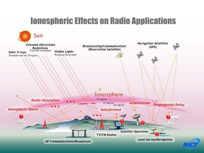
4 SIMPLISTIC VIEW OF SITUATION WITH REGARD TO SPACE WAVES
5 MORE COMPLEX VIEW MANY MORE PATHS MOVING OBJECTS
6 MORE COMPLEX STILL NOISE GETS ADDED TO THE SYSTEM [from a variety of sources] INTERFERENCE FROM OTHER SIGNALS THAT ARE BEING TRANSMITTED WE WILL NOT BE ABLE TO TAKE EVERYTHING INTO ACCOUNT IN THE COURSE

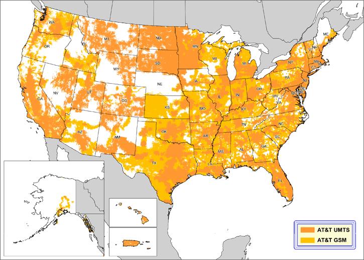
7 models
8
9
10
11 what is a model Relation between the signal radiated and signal received as a function of distance and other variables Different models Various dominating propagation mechanisms different environments (indoor-outdoor; land-sea-space; ) different applications (point-to-point, point-to-area, ) different frequency ranges Some models include random variability
12 There are tonnes of different propagation models out there!

13 location 1, free space loss is likely to give an accurate estimate of path loss. location 2, a strong line-of-sight is present, but ground reflections can significantly influence path loss. The plane earth loss model appears appropriate. location 3, plane earth loss needs to be corrected for significant diffraction losses, caused by trees cutting into the direct line of sight. location 4, a simple diffraction model is likely to give an accurate estimate of path loss. location 5, loss prediction fairly difficult and unreliable since multiple diffraction is involved.
14 LARGE AND SMALL SCALE MODELS RF propagation models generally characterize two aspects of RF propagation: large scale and small scale fading Large Scale propagation models predict the mean signal strength for a given transmitter and receiver separation distance and are used to predict RF coverage Friis Free Space Path Loss Model Two Ray Ground Reflection Model Log Distance Path Loss Model with Shadowing Small scale propagation models characterize the rapid fluctuations of received signal strength over short distances or a short time duration Small-scale models are generally associated with predicting multipath fading
15 Fading Fast Fading (Shortterm fading) Slow Fading (Longterm fading) Signal Strength (db) Path Loss Distance 15
16 MOVING OBJECT WILL EXPERIENCE FAST FADING MULTIPATH FADING
17 some terminology As we are mainly interested in the more complex environments of mobile communications we talk about the BS = basestation, the MS = mobile station. Sometimes the mobile station is referred to as the UE = user equipment or just the user. Sometimes the basestation might be called an access point!
18 WE ARE NOT GOING TO GET TO LOOK AT ALL THE ISSUES AND MODELS BUT IT IS GOOD TO REALISE THAT MANY EXIST!
19 Fading Fast Fading (Shortterm fading) Slow Fading (Longterm fading) Signal Strength (db) Path Loss Distance 19
20 PATH LOSS MODELS
21 Fading Fast Fading (Shortterm fading) Slow Fading (Longterm fading) Signal Strength (db) Path Loss Distance 21
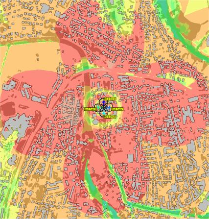
22 path loss Path loss is the phenomenon which occurs when the received signal becomes weaker and weaker due to increasing distance between mobile and base station. A transmission via a radio channel will be affected by path loss (average signal power attenuation), which is largely depending on the distance between the transmitting and receiving radio antennas. Further, characteristics of objects in the radio channel, particularly in the vicinity of the receiving MS, such as terrain, buildings and vegetation may also have a significant impact on the path loss.
23 path loss PATH loss in decreasing order: Urban area (large city) Urban area (medium and small city) Suburban area Open area

24 FOLLOWING SLIDES TAKEN FROM GREAT THESIS
25 BASICS
26
27
28 An antenna typically has a gain. ANTENNA GAIN In laymen s terms, antenna gain refers to the ability of the antenna to focus scattered RF waves into a narrower, useful plane, thereby increasing signal strength. Normally antenna gain is expressed in db The letter G is used to denote it
29 this world is obsessed with dbs
30
31 going beyond free space
32 plane earth model
33

34
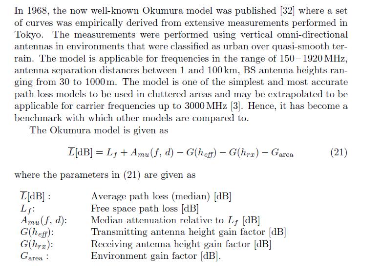
35 Okumura s Model Okumura s model is one of the most frequently used macroscopic propagation models. It was developed during the mid 1960's as the result of large-scale studies conducted in and around Tokyo. The model was designed for use in the frequency range 200 up to 1920 MHz and mostly in an urban propagation environment.
36
37 additional notes in the following slides taken from: /Old%20Notes/RF%20Propagation%20-%2007- Okumura%20and%20Hata%20Macroscopic%2 0Propagation%20Models.pdf
38
")
39 A mu (f,d)
40
41
 curves.")
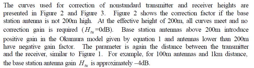
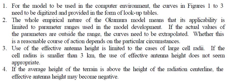
42 antenna gain factors to take into account the antennas are not at the heights for the previous A mu (f,d) curves. Figure 2
 curves.")
43 antenna gain factors to take into account the antennas are not at the heights for the previous A mu (f,d) curves. Figure 3
44 Okumura s model has a db empirical standard deviation between the path loss predicted by the model and the path loss associated with one of the measurements used to develop the model
45
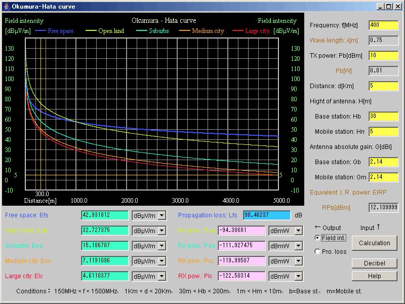
46 advancing on Okumura The so-called Okumura-Hata curve is an approximation of radio wave propagation characteristics based on aggregated data obtained in actual tests of propagation characteristics between a base station and mobile stations in various areas, such as open land, suburbs, a medium city, and a large city. The electric field intensity for each area is calculated by applying a correction value to the standard field intensity, which is that of an urban area in quasi-smooth terrain.

47 Okumura Hata
48
49
50
51
52

53
54
55 exercise Plot a series of curves comparing the functionality of the free space and plane earth model for different distances and frequencies. Assume isotropic antennas
56 some calculations for you to do... what happens to the free space loss every time the carrier frequency is doubled? every time the separation between antennas is doubled? what does this tell you about how you might structure a network??
Chapter 3. Mobile Radio Propagation
 Chapter 3 Mobile Radio Propagation Based on the slides of Dr. Dharma P. Agrawal, University of Cincinnati and Dr. Andrea Goldsmith, Stanford University Propagation Mechanisms Outline Radio Propagation
Section 1 Wireless Transmission
 Part : Wireless Communication! section : Wireless Transmission! Section : Digital modulation! Section : Multiplexing/Medium Access Control (MAC) Section Wireless Transmission Intro. to Wireless Transmission
Wireless Communication Fundamentals Feb. 8, 2005
 Wireless Communication Fundamentals Feb. 8, 005 Dr. Chengzhi Li 1 Suggested Reading Chapter Wireless Communications by T. S. Rappaport, 001 (version ) Rayleigh Fading Channels in Mobile Digital Communication
Antenna & Propagation. Basic Radio Wave Propagation
 For updated version, please click on http://ocw.ump.edu.my Antenna & Propagation Basic Radio Wave Propagation by Nor Hadzfizah Binti Mohd Radi Faculty of Electric & Electronics Engineering hadzfizah@ump.edu.my
Chapter 1: Telecommunication Fundamentals
 Chapter 1: Telecommunication Fundamentals Block Diagram of a communication system Noise n(t) m(t) Information (base-band signal) Signal Processing Carrier Circuits s(t) Transmission Medium r(t) Signal
Radio Propagation Fundamentals
 Radio Propagation Fundamentals Concept of Electromagnetic Wave Propagation Mechanisms Modes of Propagation Propagation Models Path Profiles Link Budget Fading Channels Electromagnetic (EM) Waves EM Wave
Mobile Radio Wave propagation channel- Path loss Models
 Mobile Radio Wave propagation channel- Path loss Models 3.1 Introduction The wireless Communication is one of the integral parts of society which has been a focal point for sharing information with different
Broad Principles of Propagation 4C4
 Broad Principles of Propagation ledoyle@tcd.ie 4C4 Starting at the start All wireless systems use spectrum, radiowaves, electromagnetic waves to function It is the fundamental and basic ingredient of
Mobile Communications
 Mobile Communications Part IV- Propagation Characteristics Professor Z Ghassemlooy School of Computing, Engineering and Information Sciences University of Northumbria U.K. http://soe.unn.ac.uk/ocr Contents
Propagation Modelling White Paper
 Propagation Modelling White Paper Propagation Modelling White Paper Abstract: One of the key determinants of a radio link s received signal strength, whether wanted or interfering, is how the radio waves
Contents. ITS323: Introduction to Data Communications CSS331: Fundamentals of Data Communications. Transmission Media and Spectrum.
 2 ITS323: Introduction to Data Communications CSS331: Fundamentals of Data Communications Sirindhorn International Institute of Technology Thammasat University Prepared by Steven Gordon on 3 August 2015
ITS323: Introduction to Data Communications CSS331: Fundamentals of Data Communications
 ITS323: Introduction to Data Communications CSS331: Fundamentals of Data Communications Sirindhorn International Institute of Technology Thammasat University Prepared by Steven Gordon on 3 August 2015
3C5 Telecommunications. what do radios look like? mobile phones. Linda Doyle CTVR The Telecommunications Research Centre
 3C5 Telecommunications what do radios look like? Linda Doyle CTVR The Telecommunications Research Centre ledoyle@tcd.ie Oriel/Dunlop House 2009 mobile phones talk is cheap.. bluetooth 3G WLAN/802.11 GSM
The Radio Channel. COS 463: Wireless Networks Lecture 14 Kyle Jamieson. [Parts adapted from I. Darwazeh, A. Goldsmith, T. Rappaport, P.
 The Radio Channel COS 463: Wireless Networks Lecture 14 Kyle Jamieson [Parts adapted from I. Darwazeh, A. Goldsmith, T. Rappaport, P. Steenkiste] Motivation The radio channel is what limits most radio
Simulation of Outdoor Radio Channel
 Simulation of Outdoor Radio Channel Peter Brída, Ján Dúha Department of Telecommunication, University of Žilina Univerzitná 815/1, 010 6 Žilina Email: brida@fel.utc.sk, duha@fel.utc.sk Abstract Wireless
ECE 476/ECE 501C/CS Wireless Communication Systems Winter Lecture 6: Fading
 ECE 476/ECE 501C/CS 513 - Wireless Communication Systems Winter 2003 Lecture 6: Fading Last lecture: Large scale propagation properties of wireless systems - slowly varying properties that depend primarily
RRC Vehicular Communications Part II Radio Channel Characterisation
 RRC Vehicular Communications Part II Radio Channel Characterisation Roberto Verdone Slides are provided as supporting tool, they are not a textbook! Outline 1. Fundamentals of Radio Propagation 2. Large
UNIT Derive the fundamental equation for free space propagation?
 UNIT 8 1. Derive the fundamental equation for free space propagation? Fundamental Equation for Free Space Propagation Consider the transmitter power (P t ) radiated uniformly in all the directions (isotropic),
Determination of Propagation Path Loss and Contour Map for Adaba FM Radio Station in Akure Nigeria
 International Journal of Science and Technology Volume 2 No. 9, September, 2013 Determination of Propagation Path Loss and Contour Map for Adaba FM Radio Station in Akure Nigeria Oyetunji S. A, Alowolodu
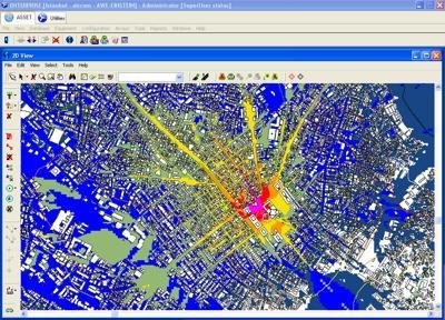
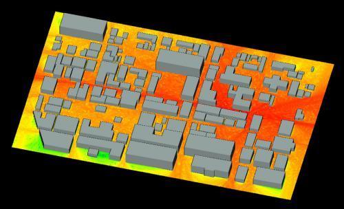
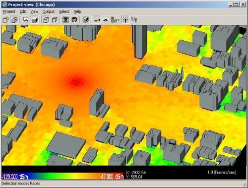
Supporting Network Planning Tools II
 Session 5.8 Supporting Network Planning Tools II Roland Götz LS telcom AG / Spectrocan 1 Modern Radio Network Planning Tools Radio Network Planning Tool Data / Result Output Data Management Network Processor
Review of Path Loss models in different environments
 Review of Path Loss models in different environments Mandeep Kaur 1, Deepak Sharma 2 1 Computer Scinece, Kurukshetra Institute of Technology and Management, Kurukshetra 2 H.O.D. of CSE Deptt. Abstract
Wireless Transmission Rab Nawaz Jadoon
 Wireless Transmission Rab Nawaz Jadoon DCS Assistant Professor COMSATS IIT, Abbottabad Pakistan COMSATS Institute of Information Technology Mobile Communication Frequency Spectrum Note: The figure shows
(Refer Slide Time: 00:01:31 min)
") Wireless Communications Dr. Ranjan Bose Department of Electrical Engineering Indian Institute of Technology, Delhi Lecture No. # 12 Mobile Radio Propagation (Continued) We will start today s lecture with
Wireless Communications Dr. Ranjan Bose Department of Electrical Engineering Indian Institute of Technology, Delhi Lecture No. # 12 Mobile Radio Propagation (Continued) We will start today s lecture with
Vehicle Networks. Wireless communication basics. Univ.-Prof. Dr. Thomas Strang, Dipl.-Inform. Matthias Röckl
 Vehicle Networks Wireless communication basics Univ.-Prof. Dr. Thomas Strang, Dipl.-Inform. Matthias Röckl Outline Wireless Signal Propagation Electro-magnetic waves Signal impairments Attenuation Distortion
ECE 476/ECE 501C/CS Wireless Communication Systems Winter Lecture 6: Fading
 ECE 476/ECE 501C/CS 513 - Wireless Communication Systems Winter 2004 Lecture 6: Fading Last lecture: Large scale propagation properties of wireless systems - slowly varying properties that depend primarily
ECE 476/ECE 501C/CS Wireless Communication Systems Winter Lecture 6: Fading
 ECE 476/ECE 501C/CS 513 - Wireless Communication Systems Winter 2005 Lecture 6: Fading Last lecture: Large scale propagation properties of wireless systems - slowly varying properties that depend primarily
Revision of Lecture One
 Revision of Lecture One System blocks and basic concepts Multiple access, MIMO, space-time Transceiver Wireless Channel Signal/System: Bandpass (Passband) Baseband Baseband complex envelope Linear system:
Chapter 1 Introduction
 Wireless Information Transmission System Lab. Chapter 1 Introduction National Sun Yat-sen University Table of Contents Elements of a Digital Communication System Communication Channels and Their Wire-line
Evaluation of Power Budget and Cell Coverage Range in Cellular GSM System
 Evaluation of Power Budget and Cell Coverage Range in Cellular GSM System Dr. S. A. Mawjoud samialmawjoud_2005@yahoo.com Abstract The paper deals with study of affecting parameters on the communication
Revision of Lecture One
 Revision of Lecture One System block Transceiver Wireless Channel Signal / System: Bandpass (Passband) Baseband Baseband complex envelope Linear system: complex (baseband) channel impulse response Channel:
RECOMMENDATION ITU-R P The prediction of the time and the spatial profile for broadband land mobile services using UHF and SHF bands
 Rec. ITU-R P.1816 1 RECOMMENDATION ITU-R P.1816 The prediction of the time and the spatial profile for broadband land mobile services using UHF and SHF bands (Question ITU-R 211/3) (2007) Scope The purpose
David Tipper. Graduate Telecommunications and Networking Program
 Wireless Communication Fundamentals David Tipper Associate Professor Graduate Telecommunications and Networking Program University it of Pittsburgh Telcom 2700 Slides 2 Wireless Networks Wireless Wide
Rec. ITU-R P RECOMMENDATION ITU-R P PROPAGATION BY DIFFRACTION. (Question ITU-R 202/3)
") Rec. ITU-R P.- 1 RECOMMENDATION ITU-R P.- PROPAGATION BY DIFFRACTION (Question ITU-R 0/) Rec. ITU-R P.- (1-1-1-1-1-1-1) The ITU Radiocommunication Assembly, considering a) that there is a need to provide
Rec. ITU-R P.- 1 RECOMMENDATION ITU-R P.- PROPAGATION BY DIFFRACTION (Question ITU-R 0/) Rec. ITU-R P.- (1-1-1-1-1-1-1) The ITU Radiocommunication Assembly, considering a) that there is a need to provide
UNDER STANDING RADIO FREQUENCY Badger Meter, Inc.
 UNDER STANDING RADIO FREQUENCY UNDERSTANDING RADIO FREQUENCY Regional Sales Meeting March 1-2, 2011 Brian Fiut Sr. Product Manager Itron Inc. Liberty Lake, WA August 25, 2010 RADIO PROPAGATION Radio consists
Application Note 37. Emulating RF Channel Characteristics
 Application Note 37 Emulating RF Channel Characteristics Wireless communication is one of the most demanding applications for the telecommunications equipment designer. Typical signals at the receiver
E-716-A Mobile Communications Systems. Lecture #2 Basic Concepts of Wireless Transmission (p1) Instructor: Dr. Ahmad El-Banna
 Instructor: Dr. Ahmad El-Banna") October 2014 Ahmad El-Banna Integrated Technical Education Cluster At AlAmeeria E-716-A Mobile Communications Systems Lecture #2 Basic Concepts of Wireless Transmission (p1) Instructor: Dr. Ahmad El-Banna
October 2014 Ahmad El-Banna Integrated Technical Education Cluster At AlAmeeria E-716-A Mobile Communications Systems Lecture #2 Basic Concepts of Wireless Transmission (p1) Instructor: Dr. Ahmad El-Banna
Radio Communication. Presentation created by: András Balogh
 Radio Communication Presentation created by: András Balogh AM and FM The goal is to transmit a modulating signal S(t) via a wave sin(ωt). In case of AM, the product of the modulation is f(t)=(a+s(t))*sin(ωt);
Mobile Radio Propagation Channel Models
 Wireless Information Transmission System Lab. Mobile Radio Propagation Channel Models Institute of Communications Engineering National Sun Yat-sen University Table of Contents Introduction Propagation
Information on the Evaluation of VHF and UHF Terrestrial Cross-Border Frequency Coordination Requests
 Issue 1 May 2013 Spectrum Management and Telecommunications Technical Bulletin Information on the Evaluation of VHF and UHF Terrestrial Cross-Border Frequency Coordination Requests Aussi disponible en
Data and Computer Communications Chapter 4 Transmission Media
 Data and Computer Communications Chapter 4 Transmission Media Ninth Edition by William Stallings Data and Computer Communications, Ninth Edition by William Stallings, (c) Pearson Education - Prentice Hall,
Session2 Antennas and Propagation
 Wireless Communication Presented by Dr. Mahmoud Daneshvar Session2 Antennas and Propagation 1. Introduction Types of Anttenas Free space Propagation 2. Propagation modes 3. Transmission Problems 4. Fading
Path-loss and Shadowing (Large-scale Fading) PROF. MICHAEL TSAI 2015/03/27
 PROF. MICHAEL TSAI 2015/03/27") Path-loss and Shadowing (Large-scale Fading) PROF. MICHAEL TSAI 2015/03/27 Multipath 2 3 4 5 Friis Formula TX Antenna RX Antenna = 4 EIRP= Power spatial density 1 4 6 Antenna Aperture = 4 Antenna Aperture=Effective
Path-loss and Shadowing (Large-scale Fading) PROF. MICHAEL TSAI 2015/03/27 Multipath 2 3 4 5 Friis Formula TX Antenna RX Antenna = 4 EIRP= Power spatial density 1 4 6 Antenna Aperture = 4 Antenna Aperture=Effective
Lecture - 06 Large Scale Propagation Models Path Loss
 Fundamentals of MIMO Wireless Communication Prof. Suvra Sekhar Das Department of Electronics and Communication Engineering Indian Institute of Technology, Kharagpur Lecture - 06 Large Scale Propagation
Empirical Path Loss Models
 Empirical Path Loss Models 1 Free space and direct plus reflected path loss 2 Hata model 3 Lee model 4 Other models 5 Examples Levis, Johnson, Teixeira (ESL/OSU) Radiowave Propagation August 17, 2018 1
2016/10/14. YU Xiangyu
 2016/10/14 YU Xiangyu yuxy@scut.edu.cn Frequency and Spectrum Types of Waves Propagation Model Free-Space Propagation Path Loss Fading: Slow Fading / Fast Fading Doppler Shift Delay Spread FIGURE Electromagnetic
CHAPTER 2 WIRELESS CHANNEL
 CHAPTER 2 WIRELESS CHANNEL 2.1 INTRODUCTION In mobile radio channel there is certain fundamental limitation on the performance of wireless communication system. There are many obstructions between transmitter
Introduction to Wireless Electromagnetic Channels & Large Scale Fading*
 EE-546 Wireless Communication Technologies Spring 005 Introduction to Wireless Electromagnetic Channels & Large Scale Fading* Rahul N. Pupala pupala@winlab.rutgers.edu Department of Electrical Engineering
S Channel Modeling for Radio Communication Systems (3 credits)
") Helsinki University of Technology Communications Laboratory 2.10.2007/sgh 1 S-72.3210 Channel Modeling for Radio Communication Systems (3 credits) Course presentation, Period II, 2007 2008 Course status:
Helsinki University of Technology Communications Laboratory 2.10.2007/sgh 1 S-72.3210 Channel Modeling for Radio Communication Systems (3 credits) Course presentation, Period II, 2007 2008 Course status:
Abstract. Propagation tests for land-mobile radio service
 Abstract Propagation tests for land-mobile radio service VHF (200MHz) and UHF (453, 922, 1310, 1430, 1920MHz) Various situations of irregular terrain/environmental clutter The results analyzed statistically
Near-Earth Propagation Models
 CHAPTER 7 Near-Earth Propagation Models 7.1 INTRODUCTION Many applications require RF or microwave propagation from point to point very near the earth s surface and in the presence of various impairments.
PART 1 RECOMMENDATION ITU-R P.1144 GUIDE TO THE APPLICATION OF THE PROPAGATION METHODS OF RADIOCOMMUNICATION STUDY GROUP 3
 Rec. ITU-R P.1144 1 PART 1 SECTION P-A: TEXTS OF GENERAL INTEREST Rec. ITU-R P.1144 RECOMMENDATION ITU-R P.1144 GUIDE TO THE APPLICATION OF THE PROPAGATION METHODS OF RADIOCOMMUNICATION STUDY GROUP 3 (1995)
Antennas and Propagation
 CMPE 477 Wireless and Mobile Networks Lecture 3: Antennas and Propagation Antennas Propagation Modes Line of Sight Transmission Fading in the Mobile Environment Introduction An antenna is an electrical
PRINCIPLES OF COMMUNICATION SYSTEMS. Lecture 1- Introduction Elements, Modulation, Demodulation, Frequency Spectrum
 PRINCIPLES OF COMMUNICATION SYSTEMS Lecture 1- Introduction Elements, Modulation, Demodulation, Frequency Spectrum Topic covered Introduction to subject Elements of Communication system Modulation General
CHAPTER 6 THE WIRELESS CHANNEL
 CHAPTER 6 THE WIRELESS CHANNEL These slides are made available to faculty in PowerPoint form. Slides can be freely added, modified, and deleted to suit student needs. They represent substantial work on
UNIK4230: Mobile Communications Spring 2013
 UNIK4230: Mobile Communications Spring 2013 Abul Kaosher abul.kaosher@nsn.com Mobile: 99 27 10 19 1 UNIK4230: Mobile Communications Propagation characteristis of wireless channel Date: 07.02.2013 2 UNIK4230:
RECOMMENDATION ITU-R P ATTENUATION IN VEGETATION. (Question ITU-R 202/3)
") Rec. ITU-R P.833-2 1 RECOMMENDATION ITU-R P.833-2 ATTENUATION IN VEGETATION (Question ITU-R 2/3) Rec. ITU-R P.833-2 (1992-1994-1999) The ITU Radiocommunication Assembly considering a) that attenuation
Rec. ITU-R P.833-2 1 RECOMMENDATION ITU-R P.833-2 ATTENUATION IN VEGETATION (Question ITU-R 2/3) Rec. ITU-R P.833-2 (1992-1994-1999) The ITU Radiocommunication Assembly considering a) that attenuation
Neural Network Approach to Model the Propagation Path Loss for Great Tripoli Area at 900, 1800, and 2100 MHz Bands *
 Neural Network Approach to Model the Propagation Path Loss for Great Tripoli Area at 9, 1, and 2 MHz Bands * Dr. Tammam A. Benmus Eng. Rabie Abboud Eng. Mustafa Kh. Shater EEE Dept. Faculty of Eng. Radio
Project = An Adventure : Wireless Networks. Lecture 4: More Physical Layer. What is an Antenna? Outline. Page 1
 Project = An Adventure 18-759: Wireless Networks Checkpoint 2 Checkpoint 1 Lecture 4: More Physical Layer You are here Done! Peter Steenkiste Departments of Computer Science and Electrical and Computer
Elements of Communication System Channel Fig: 1: Block Diagram of Communication System Terminology in Communication System
 Content:- Fundamentals of Communication Engineering : Elements of a Communication System, Need of modulation, electromagnetic spectrum and typical applications, Unit V (Communication terminologies in communication
Channel Modelling ETIM10. Propagation mechanisms
 Channel Modelling ETIM10 Lecture no: 2 Propagation mechanisms Ghassan Dahman \ Fredrik Tufvesson Department of Electrical and Information Technology Lund University, Sweden 2012-01-20 Fredrik Tufvesson
WIRELESS TRANSMISSION
 COMP 635: WIRELESS NETWORKS WIRELESS TRANSMISSION Jasleen Kaur Fall 205 Outline Frequenc Spectrum Ø Usage and Licensing Signals and Antennas Ø Propagation Characteristics Multipleing Ø Space, Frequenc,
ELEG 5693 Wireless Communications Propagation and Noise Part I
 Department of Electrical Engineering University of Arkansas ELEG 5693 Wireless Communications ropagation and Noise art I Dr. Jingxian Wu wuj@uark.edu OULINE 2 Wireless channel ath loss Shadowing Small
Antennas and Propagation
 Antennas and Propagation Chapter 5 Introduction An antenna is an electrical conductor or system of conductors Transmission - radiates electromagnetic energy into space Reception - collects electromagnetic
Multipath fading effects on short range indoor RF links. White paper
 ALCIOM 5, Parvis Robert Schuman 92370 CHAVILLE - FRANCE Tel/Fax : 01 47 09 30 51 contact@alciom.com www.alciom.com Project : Multipath fading effects on short range indoor RF links DOCUMENT : REFERENCE
Ad hoc and Sensor Networks Chapter 4: Physical layer. Holger Karl
 Ad hoc and Sensor Networks Chapter 4: Physical layer Holger Karl Goals of this chapter Get an understanding of the peculiarities of wireless communication Wireless channel as abstraction of these properties
Chapter 2: Wireless Transmission. Mobile Communications. Spread spectrum. Multiplexing. Modulation. Frequencies. Antenna. Signals
 Mobile Communications Chapter 2: Wireless Transmission Frequencies Multiplexing Signals Spread spectrum Antenna Modulation Signal propagation Cellular systems Prof. Dr.-Ing. Jochen Schiller, http://www.jochenschiller.de/
Channel models and antennas
 RADIO SYSTEMS ETIN15 Lecture no: 4 Channel models and antennas Anders J Johansson, Department of Electrical and Information Technology anders.j.johansson@eit.lth.se 29 March 2017 1 Contents Why do we need
Antennas & Propagation. CSG 250 Fall 2007 Rajmohan Rajaraman
 Antennas & Propagation CSG 250 Fall 2007 Rajmohan Rajaraman Introduction An antenna is an electrical conductor or system of conductors o Transmission - radiates electromagnetic energy into space o Reception
Antennas and Propagation. Chapter 6a: Propagation Definitions, Path-based Modeling
 Antennas and Propagation a: Propagation Definitions, Path-based Modeling Introduction Propagation How signals from antennas interact with environment Goal: model channel connecting TX and RX Antennas and
Experimental Evaluation Scheme of UWB Antenna Performance
 Tokyo Tech. Experimental Evaluation Scheme of UWB Antenna Performance Sathaporn PROMWONG Wataru HACHITANI Jun-ichi TAKADA TAKADA-Laboratory Mobile Communication Research Group Graduate School of Science
9 th ANNUAL DIGITAL SWITCHOVER FORUM AFRICA, IN ARUSHA, TANZANIA FROM 11 th TO 14 th FEBRUARY, 2014
 TANZANIA COMMUNICATIONS REGULATORY AUTHORITY 9 th ANNUAL DIGITAL SWITCHOVER FORUM AFRICA, IN ARUSHA, TANZANIA FROM 11 th TO 14 th FEBRUARY, 2014 A MARKET LED APPROACH TO DIGITAL DIVIDEND REVIEW FOR FINANCING
Interpretation and Classification of P-Series Recommendations in ITU-R
 Int. J. Communications, Network and System Sciences, 2016, 9, 117-125 Published Online May 2016 in SciRes. http://www.scirp.org/journal/ijcns http://dx.doi.org/10.4236/ijcns.2016.95010 Interpretation and
2018/5/21. YU Xiangyu
 2018/5/21 YU Xiangyu yuxy@scut.edu.cn Frequency and Spectrum Types of Waves Propagation Model Free-Space Propagation Path Loss Fading: Slow Fading / Fast Fading Doppler Shift Delay Spread FIGURE Electromagnetic
Radio propagation modeling on 433 MHz
 Ákos Milánkovich 1, Károly Lendvai 1, Sándor Imre 1, Sándor Szabó 1 1 Budapest University of Technology and Economics, Műegyetem rkp. 3-9. 1111 Budapest, Hungary {milankovich, lendvai, szabos, imre}@hit.bme.hu
LECTURE 3. Radio Propagation
 LECTURE 3 Radio Propagation 2 Simplified model of a digital communication system Source Source Encoder Channel Encoder Modulator Radio Channel Destination Source Decoder Channel Decoder Demod -ulator Components
Wireless Sensor Networks 4th Lecture
 Wireless Sensor Networks 4th Lecture 07.11.2006 Christian Schindelhauer schindel@informatik.uni-freiburg.de 1 Amplitude Representation Amplitude representation of a sinus curve s(t) = A sin(2π f t + ϕ)
Characterization of Mobile Radio Propagation Channel using Empirically based Pathloss Model for Suburban Environments in Nigeria
 Characterization of Mobile Radio Propagation Channel using Empirically based Pathloss Model for Suburban Environments in Nigeria Ifeagwu E.N. 1 Department of Electronic and Computer Engineering, Nnamdi
International Journal of Advance Engineering and Research Development
 Scientific Journal of Impact Factor (SJIF) : 3.134 ISSN (Print) : 2348-6406 ISSN (Online): 2348-4470 International Journal of Advance Engineering and Research Development COMPARATIVE ANALYSIS OF THREE
A bluffer s guide to Radar
 A bluffer s guide to Radar Andy French December 2009 We may produce at will, from a sending station, an electrical effect in any particular region of the globe; (with which) we may determine the relative
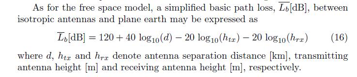
A Consideration of Propagation Loss Models for GSM during Harmattan in N djamena (Chad)
") 43 A Consideration of Propagation Loss Models for GSM during Harmattan in N djamena (Chad) D.D. DAJAB AND NALDONGAR PARFAIT * Department of Electrical and Computer Engineering, AHMADU BELLO University,
43 A Consideration of Propagation Loss Models for GSM during Harmattan in N djamena (Chad) D.D. DAJAB AND NALDONGAR PARFAIT * Department of Electrical and Computer Engineering, AHMADU BELLO University,
Liquidmetal Electromagnetic Properties & RF Shielding Overview
 Liquidmetal Electromagnetic Properties & RF Shielding Overview Liquidmetal alloy is more transparent to RF signals than many similar materials 1 Introduction H ow a material interacts with radio frequency
LRC Mobile Radio Networks Link Level: the Radio Channel
 LRC Mobile Radio Networks Link Level: the Radio Channel Roberto Verdone roberto.verdone@unibo.it +39 051 20 93817 Office Hours: Monday 4 6 pm (upon prior agreement via email) Slides are provided as supporting
Mobile Hata Model and Walkfisch Ikegami
 Calculate Path Loss in Transmitter in Global System Mobile By Using Hata Model and Ikegami Essam Ayiad Ashebany 1, Silaiman Khalifa Yakhlef 2 and A. R. Zerek 3 1 Post grade Student, Libyan Academy of Graduate
Wireless Physical Layer Concepts: Part III
 Wireless Physical Layer Concepts: Part III Raj Jain Professor of CSE Washington University in Saint Louis Saint Louis, MO 63130 Jain@cse.wustl.edu These slides are available on-line at: http://www.cse.wustl.edu/~jain/cse574-08/
RECOMMENDATION ITU-R P Guide to the application of the propagation methods of Radiocommunication Study Group 3
 Rec. ITU-R P.1144-2 1 RECOMMENDATION ITU-R P.1144-2 Guide to the application of the propagation methods of Radiocommunication Study Group 3 (1995-1999-2001) The ITU Radiocommunication Assembly, considering
Channel models and antennas
 RADIO SYSTEMS ETIN15 Lecture no: 4 Channel models and antennas Ove Edfors, Department of Electrical and Information Technology Ove.Edfors@eit.lth.se 2012-03-21 Ove Edfors - ETIN15 1 Contents Why do we
λ iso d 4 π watt (1) + L db (2)
 + L db (2)") 1 Path-loss Model for Broadcasting Applications and Outdoor Communication Systems in the VHF and UHF Bands Constantino Pérez-Vega, Member IEEE, and José M. Zamanillo Communications Engineering Department
1 Path-loss Model for Broadcasting Applications and Outdoor Communication Systems in the VHF and UHF Bands Constantino Pérez-Vega, Member IEEE, and José M. Zamanillo Communications Engineering Department
Antennas and Propagation. Prelude to Chapter 4 Propagation
 Antennas and Propagation Prelude to Chapter 4 Propagation Introduction An antenna is an electrical conductor or system of conductors for: Transmission - radiates electromagnetic energy into space (involves
Introduction. TV Coverage and Interference, February 06, 2004.
 A New Prediction Model for M/H Mobile DTV Service Prepared for OMVC June 28, 2011 Charles Cooper, du Treil, Lundin & Rackley, Inc. Victor Tawil, National Association of Broadcasters Introduction The Open
Technician License Course Chapter 2 Radio and Signals Fundamentals
 Technician License Course Chapter 2 Radio and Signals Fundamentals Handling Large and Small Numbers Electronics and Radio use a large range of sizes, i.e., 0.000000000001 to 1000000000000. Scientific Notation
EC 551 Telecommunication System Engineering. Mohamed Khedr
 EC 551 Telecommunication System Engineering Mohamed Khedr http://webmail.aast.edu/~khedr 1 Mohamed Khedr., 2008 Syllabus Tentatively Week 1 Week 2 Week 3 Week 4 Week 5 Week 6 Week 7 Week 8 Week 9 Week
RESEACH MEASUREMENTS OF RADIOWAVE SIGNAL STRENGHT AND PATH LOSS PROPAGATION USING EGLI MODEL. By: NAWAWI BIN ISMAIL
 RESEACH MEASUREMENTS OF RADIOWAVE SIGNAL STRENGHT AND PATH LOSS PROPAGATION USING EGLI MODEL By: NAWAWI BIN ISMAIL 1 Prepare By: Nawawi Bin Ismail TITLE: Measurement Of Radiowave Signal Strength And Path
Propagation curves and conditions of validity (homogeneous paths)
") Rec. ITU-R P.368-7 1 RECOMMENDATION ITU-R P.368-7 * GROUND-WAVE PROPAGATION CURVES FOR FREQUENCIES BETWEEN 10 khz AND 30 MHz (1951-1959-1963-1970-1974-1978-1982-1986-1990-1992) Rec. 368-7 The ITU Radiocommunication
Rec. ITU-R P.368-7 1 RECOMMENDATION ITU-R P.368-7 * GROUND-WAVE PROPAGATION CURVES FOR FREQUENCIES BETWEEN 10 khz AND 30 MHz (1951-1959-1963-1970-1974-1978-1982-1986-1990-1992) Rec. 368-7 The ITU Radiocommunication
Lecture 1 Wireless Channel Models
 MIMO Communication Systems Lecture 1 Wireless Channel Models Prof. Chun-Hung Liu Dept. of Electrical and Computer Engineering National Chiao Tung University Spring 2017 2017/3/2 Lecture 1: Wireless Channel
A Terrestrial Multiple-Receiver Radio Link Experiment at 10.7 GHz - Comparisons of Results with Parabolic Equation Calculations
 RADIOENGINEERING, VOL. 19, NO. 1, APRIL 2010 117 A Terrestrial Multiple-Receiver Radio Link Experiment at 10.7 GHz - Comparisons of Results with Parabolic Equation Calculations Pavel VALTR 1, Pavel PECHAC
MSIT 413: Wireless Technologies Week 3
 MSIT 413: Wireless Technologies Week 3 Michael L. Honig Department of EECS Northwestern University January 2016 Why Study Radio Propagation? To determine coverage Can we use the same channels? Must determine
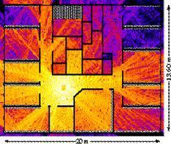
Development of a Wireless Communications Planning Tool for Optimizing Indoor Coverage Areas
 Development of a Wireless Communications Planning Tool for Optimizing Indoor Coverage Areas A. Dimitriou, T. Vasiliadis, G. Sergiadis Aristotle University of Thessaloniki, School of Engineering, Dept.
5.9 GHz V2X Modem Performance Challenges with Vehicle Integration
 5.9 GHz V2X Modem Performance Challenges with Vehicle Integration October 15th, 2014 Background V2V DSRC Why do the research? Based on 802.11p MAC PHY ad-hoc network topology at 5.9 GHz. Effective Isotropic
[db] Path loss free space Valid only in Far Field. Far Field Region d>df. df=2d 2 /λ
![[db] Path loss free space Valid only in Far Field. Far Field Region d>df. df=2d 2 /λ](/thumbs/79/79937534.jpg "[db] Path loss free space Valid only in Far Field. Far Field Region d>df. df=2d 2 /λ") Fundamentals of Propagation and Basic Equations. Outdoor Propagation Indoor Propagation Models to compute PL and Preceived in Outdoor and Indoor Communications. Examples of real situations. Gustavo Fano
Fundamentals of Propagation and Basic Equations. Outdoor Propagation Indoor Propagation Models to compute PL and Preceived in Outdoor and Indoor Communications. Examples of real situations. Gustavo Fano
UHF Radio Frequency Propagation Model for Akure Metropolis
 Abstract Research Journal of Engineering Sciences ISSN 2278 9472 UHF Radio Frequency Propagation Model for Akure Metropolis Famoriji J.O. and Olasoji Y.O. Federal University of Technology, Akure, Nigeria