Compact OAM Microscope for Edge Enhancement of Biomedical and Object Samples
|
|
|
- Victoria Gilbert
- 5 years ago
- Views:
Transcription
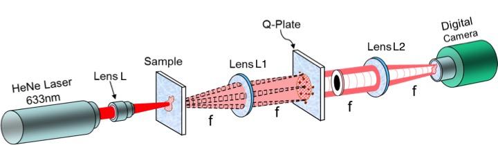
1 Compact OAM Microscope for Edge Enhancement of Biomedical and Object Samples Richard Gozali, 1 Thien-An Nguyen, 1 Ethan Bendau, 1 Robert R. Alfano 1,b) 1 City College of New York, Institute for Ultrafast Spectroscopy and Lasers, Complex Light Center, Department of Physics, 160 Convent Avenue, New York 10031, USA The production of orbital angular momentum (OAM) by using a q-plate, which functions as an electrically-tunable spatial frequency filter, provides a simple and efficient method of edge contrast in biological and medical sample imaging for histological evaluation of tissue, smears and PAP smears. An instrument producing OAM, such as a q-plate, situated at the Fourier plane of a 4f lens system, similar to the use of a high-pass spatial filter, allows the passage of high spatial frequencies and enables the production of an image with highly illuminated edges contrasted against a dark background for both opaque and transparent objects. Compared with ordinary spiral phase plates and Spatial Light Modulators (SLM), the q-plate has the added advantage of electric control and tunability. I. INTRODUCTION Biological and medical samples are often transparent, showing little contrast under a microscope without the addition of contrasting dyes. However, these dyes can interact with the sample in a way that obscures observation, either by altering or killing the samples. Dark-field microscopy and phase-contrast microscopy are methods of achieving image contrast without the need to stain a sample with a dye. In darkfield microscopy, by rejecting light that transmits directly through a sample and collecting only the light scattered from a material interface, one can achieve a high contrast image of a transparent sample. The background of the image appears dark (hence, dark field ) and the light-scattering interfaces will appear bright. 1 Phase contrast microscopy provides additional image contrast that includes the internal structure of the sample. In regions with differences in refractive index and path length, transmitted and scattered light will undergo different phase changes. Phase contrast microscopy works by recombining and interfering the directly transmitted and scattered light. In this way, the relative difference in phase between light waves will produce variations in intensity in the image plane that corresponds to different features of the sample. 1 A properly designed filter at the Fourier plane of a 4f system aimed to remove low spatial frequencies can improve imaging through scattering media, for example by highlighting only the edges of a sample. 2-4 This is termed edge enhancement. Spiral plates are also known to produce high-quality edge selective enhancement by acting as spatial filters in standard bright field microscopes. Spiral phase filtering can also achieve orientation-selective edge enhancement. In contrast to isotropic edge enhancement, where all edges are equally illuminated regardless of orientation, orientation-selective edge enhancement is dependent on the orientation of the edges. This allows for further specificity in enhancement of certain features that could be more significant for observation. Previous experiment of OAM microscopy has been done by Ritsch-Marte et al. producing edge enhancement imaging of different samples where they used a spatial light modulator (SLM) in their setup 5,6. Problems regarding using the SLM are they can only reflect light, thus leading to back-folded optical setup and need extra spiral phase filtering for edges to be clearly illuminated. The q-plate, a new liquid crystal technology developed by Marucci et al. 7 is an optical element with a constant half-wave retardance across its aperture as well as a pattern of electrically-addressed birefringent liquid crystals. By running a voltage across the q-plate, the liquid crystals orient such that the alignment of their fast axis rotates around a central topological defect. This central defect causes the central vector components of the beam to cancel and the rotating fast axis imparts a helically varying phase of exp[2qiφ] around the beam, where q is the topological charge, where in this case q =, that defines the defect and fastaxis orientations. 8 The helically varying phase exp[2qiφ] is also equal to exp[ilφ], where l represents
2 the angular momentum number of a Laguerre-Gaussian beam, with l = 1. A q-plate can be tuned by frequency, voltage and temperature to operate at a range of wavelengths and, if desired, to affect the output polarization of a beam. The focus of this paper is to demonstrate and design an experimental setup with the use of OAM beams via the convenience of having a q-plate at the Fourier plane of a 4f system in order to produce images with edge contrast enhancement. Using a q-plate at the Fourier plane of a 4f system enables the beam to propagate in the shape of a donut where the illumination of the ring contains only the high spatial frequencies, thus enabling to create an image of an object with edge enhancement. Compared to standard spiral phase plates, a q-plate has the added advantage of tunability by frequency, voltage and temperature, as well as the ability to be turned on and off unlike static phase plates. 7 In comparison to using an SLM, the implementation of q-plate to a 4f OAM microscopy setup does not need to be with backfolded geometry, since q-plates are transmittive and does not need extra use of spiral phase filtering, since a q-plate also acts as a spiral phase filter. Unlike that of phase contrast microscopy the q-plate does not need an annular diaphragm and diffraction plate to alter the brightness between the in and out of phase light. 1 FIG. 1. Diagram of the 4f q-plate dark field OAM microscopy setup. II. THEORY Our 4f imaging system, shown in Figure 1, works by placing a sample in the object plane of a Fourier transform lens L1 and a q-plate in its Fourier plane. The q-plate, acting as a spatial filter, then transmits light only in a desired spatial frequency range. This light is collected and refocused by a second Fourier transform lens L2, placed such that the object plane of L2 coincides with the Fourier plane of L1. L2 performs an inverse Fourier transform of the transmitted light. The refocused light captured by a digital camera placed at the Fourier plane of L2 then is a reconstructed image of the sample, minus the components of the light filtered at particular frequencies. Analysis of the light in the Fourier plane of a Fourier transform lens imaging an illuminated object shows that general characteristics like shapes and large scale intensity variations are associated with lower spatial frequencies, while finer details like sharp curves and edges are associated with higher frequencies. Therefore, one would expect that the edge enhancement achieved in this experiment is related to an isolation of higher spatial frequencies. The q-plate alters the phase profile of the transmitted beam such that the k-vectors near the central axis of the beam, which pass through the region near the topological defect, rotate so as to point toward the axis. The result is that, due to the canceling of the k-vectors near the axis, a dark vortex region appears along the beam axis. This effectively filters out the central and lower spatial frequencies of the incident beam allowing only the higher spatial frequencies near the perimeter of the beam to pass. The radius of the ring of higher-order LG beams scales positively with the angular momentum number of a Laguerre-Gaussian beam l. We performed a computational analysis of how the distribution of transmitted spatial frequencies might change with increasing value of l to verify that higher-order LG beams will more efficiently filter low frequencies and pass high frequencies. An equation describing the spatial filter H(ρ,φ) is being represented by the following components: the beam waist w, the focal length f of the focusing lens and the value of l. Using the MATLAB program, it will then compute the Fourier transform, h(r,θ), of a Gaussian beam transmitted through such a filter, display the image produced in the Fourier plane and plot the distribution of spatial frequencies along a given axial line of the Fourier plane. A Laguerre Gaussian spatial filter for arbitrary values of l can be represented as: l H(, ) = w exp 2 exp(-il ) (1) w 2 Where ρ is the radius and ϕ the angle of polar coordinates in the Fourier plane, w is the beam waist. The equation for the Fourier transform through a lens of focal length f with a beam of wavelength λ is given by: h(r, ) = 1 i f 2 H(, )exp i 2 r cos d d (2) f 0 0 Where the function, is being represented in polar coordinates with r being the radius and θ being the angle. As seen in Figure 2, a Gaussian beam with no spatial filtering contains primarily low frequencies centered around the central peak. Here all spatial frequencies are clustered around the beam axis, as expected with a Gaussian distribution. With the spatial filter applied, a cluster of frequencies appear


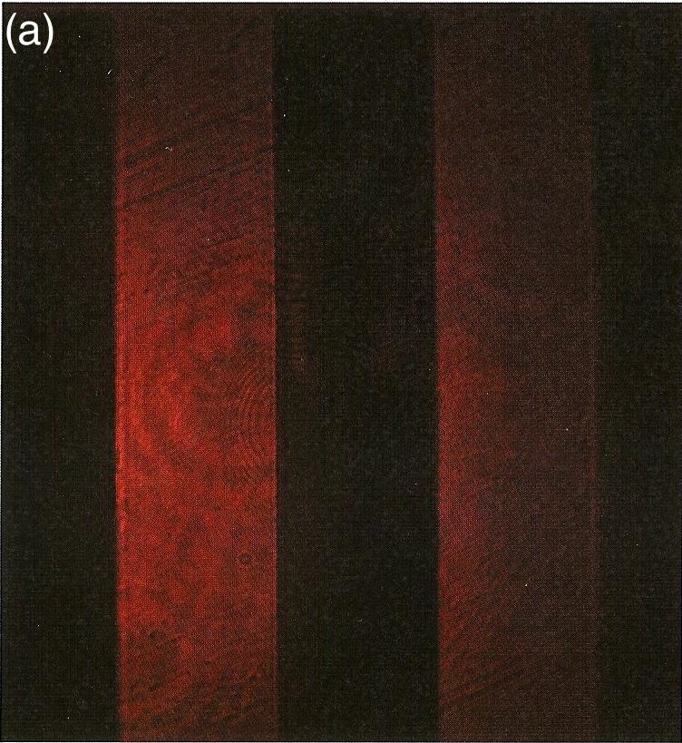
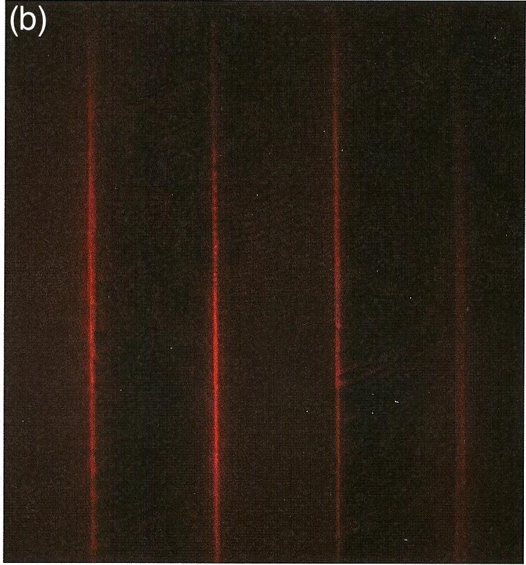
3 symmetrically on either side of the axis with a region of zero intensity between. For higher values of l, this central zero region increases and the beam composition takes on primarily higher and higher spatial frequencies. Thus our assumption is supported that the highfrequency components of the beam are those that go on to produce the final edge-enhanced image. FIG. 2. Vortex beams of higher l number consist of more higher and fewer lower spatial frequencies. The edge-enhancing spatial filtering by the q-plate is demonstrated in Figure 3 with test samples of thin metal wires. Figure 3a shows the image obtained of the metal wires with no voltage applied (i.e. the q-plate acts simply as a constant half-wave retarder and does not produce a vortex) and Figure 3b shows the image obtained with an applied voltage (i.e. the q-plate creates a central vortex, blocking the low frequencies of the beam as described). In Figure 3a, the entire length and width of the metal bar is imaged (dark against red background), as expected under standard bright-field imaging circumstances. In Figure 3b, with the q-plate on and generating a central vortex, only the edges of the metal bars are illuminated, displaying the edgeenhancement capabilities of the q-plate. Figure 4 shows a similar test with a sample of an opaque number 3 imaged with (a) and without (b) applied voltage. This test displays the isotropic edge-enhancing quality of this microscope, which allows detection of edges that are continuous curves, not simply straight-lines oriented uni-directionally as in Figure 3. We see that the edgeenhanced curves of the 3 are well-defined (edges of lower intensity are due to lower illumination intensity in that region) and there is no orientation preference in this method. III. EXPERIMENTAL The 4f OAM microscope imaging system is shown in Figure 1. A 633nm Helium-Neon laser is focused onto the sample by a microscope objective lens L, and the light is collected by a f = 75 mm focal length lens (L1) situated at a distance f behind the sample. The resulting distribution in the image plane formed by the lens L1 is the Fourier transform of the object. We place the q-plate at this Fourier plane. When there is no voltage across the q-plate, it acts as a simple half-wave retarder. When a voltage is applied with a frequency generator, about 4V at 2kHz, the liquid crystals reorient and an incident Gaussian beam is transformed into a vortex beam. The incident light is not Gaussian but is the direct and scattered light from the sample. Thus, the q-plate is acting as a filter that overlays the spiral phase qualities of a vortex beam onto the light from the sample. A second 75 mm focal length lens (L2) is placed at the focal distance behind the q-plate, which focuses the light onto a digital camera at the image plane of L2. This image is the reconstructed image of the sample after spatial filtering in which only edges, where the step height of the sample changes are highlighted and areas of constant height are dark. IV. RESULTS FIG. 3. Metal bars without voltage (a) and with voltage (b) on q-plate in 4f system. FIG. 4. Opaque number 3 without voltage (a) and with voltage (b) on q-plate in 4f system.

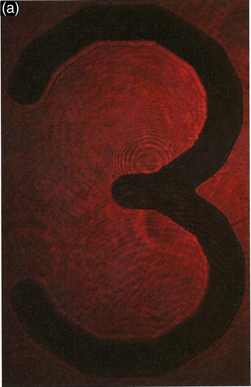
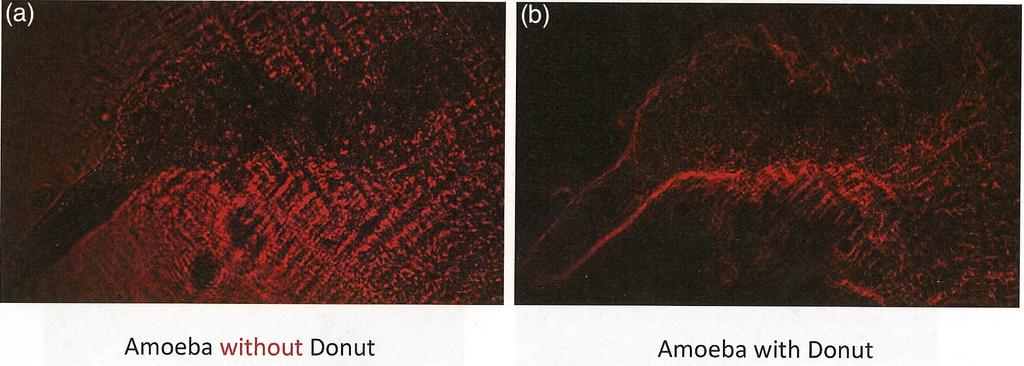
4 FIG. 5. Amoeba without voltage (a) and with voltage (b) on q-plate in 4f system Figure 5 demonstrates the edge-enhanced imaging capability for translucent media, such as biological samples. An amoeba imaged using the q-plate spatial filter shows both enhanced edges and reduced scatter noise from the glass microscope slide, whereas using standard bright-field imaging, the scattering from the slide would obscure the edges. We expect that the imaging of biological media will be the primary use of this method. V. CONCLUSION The addition of an active q-plate with charge q or any other OAM producing instrument, such as spiral phase plates or spatial light modulator, at the Fourier plane of a 4f imaging system acts as a frequencyselective spatial filter that provides enhanced contrast of sample edges. In our 4f system, this filtering is done in the Fourier plane of the first Fourier transform lens. Thus, those rays which comprise the reconstructed image of the object formed by the inverse Fourier transform lens do not include the central and lower spatial frequencies from the object. This method produces a degree of edge enhancement similar to established phase contrast imaging using static spiral phase plates, but with the added benefit of tunability for laser wavelength and the ability to turn on and off the filter. Therefore, this work has demonstrated a new compact handheld OAM microscope capable of edge enhancement imaging, shown in Figures 3, 4, and 5. Thus, we have demonstrated the viability and ease-ofuse of a q-plate spatial filter microscope that can be used to obtain images of microscopic biological samples that highlight significant features, such as relative size and detailed features, that are easily obscured under standard bright-field imaging circumstances. ACKNOWLEDGEMENTS We thank the ARO, NxGen, and Corning for supporting complex light research at The City College of New York. We thank Lorenzo Marrucci for providing q-plates for the experiment and Giovanni Milione for help. 1 S. Kumar. Textbook of Microbiology (Jaypee Brothers Medical Publishers Ltd., New Delhi, 2012) pp G.E. Anderson, F. Liu, R.R. Alfano, Optics Letters 19, 981 (1994) 3 G.Z. Wang, X. Liang, L. Wang P.P., R.R. Alfano, Optics Letters 20, 1498 (1995) 4 R.R. Alfano, W.B. Wang, L. Wang and S.K. Gayen. Photonics, Volume IV: Biomedical Photonics, Spectroscopy, and Microscopy, D.L. Andrews, ed. (John Wiley & Sons, Inc., Hoboken, 2015), pp Chap S. Furhapter, A. Jesacher, S. Bernet and M. Ritsch-Marte. Optics Express 13, (2005) 6 M. Ritsch-Marte, Phil. Trans. A. 375, (2017) 7 L. Marrucci, Journal of Nanophotonics 7, 1 (2013) 8 L. Marrucci, C. Manzo and D. Paparo. Phys. Rev. Lett. 96, (2006)
5
6
7
8

9
10
Chapter 17: Wave Optics. What is Light? The Models of Light 1/11/13
 Chapter 17: Wave Optics Key Terms Wave model Ray model Diffraction Refraction Fringe spacing Diffraction grating Thin-film interference What is Light? Light is the chameleon of the physical world. Under
Radial Polarization Converter With LC Driver USER MANUAL
 ARCoptix Radial Polarization Converter With LC Driver USER MANUAL Arcoptix S.A Ch. Trois-portes 18 2000 Neuchâtel Switzerland Mail: info@arcoptix.com Tel: ++41 32 731 04 66 Principle of the radial polarization
Confocal Imaging Through Scattering Media with a Volume Holographic Filter
 Confocal Imaging Through Scattering Media with a Volume Holographic Filter Michal Balberg +, George Barbastathis*, Sergio Fantini % and David J. Brady University of Illinois at Urbana-Champaign, Urbana,
Supplementary Figure 1. Effect of the spacer thickness on the resonance properties of the gold and silver metasurface layers.
 Supplementary Figure 1. Effect of the spacer thickness on the resonance properties of the gold and silver metasurface layers. Finite-difference time-domain calculations of the optical transmittance through
Deliverable Report. Deliverable No: D2.9 Deliverable Title: OAM waveguide transmission
 Deliverable Report Deliverable No: D2.9 Deliverable Title: OAM waveguide transmission Grant Agreement number: 255914 Project acronym: PHORBITECH Project title: A Toolbox for Photon Orbital Angular Momentum
Chapter Ray and Wave Optics
 109 Chapter Ray and Wave Optics 1. An astronomical telescope has a large aperture to [2002] reduce spherical aberration have high resolution increase span of observation have low dispersion. 2. If two
Physics 431 Final Exam Examples (3:00-5:00 pm 12/16/2009) TIME ALLOTTED: 120 MINUTES Name: Signature:
 TIME ALLOTTED: 120 MINUTES Name: Signature:") Physics 431 Final Exam Examples (3:00-5:00 pm 12/16/2009) TIME ALLOTTED: 120 MINUTES Name: PID: Signature: CLOSED BOOK. TWO 8 1/2 X 11 SHEET OF NOTES (double sided is allowed), AND SCIENTIFIC POCKET CALCULATOR
Physics 431 Final Exam Examples (3:00-5:00 pm 12/16/2009) TIME ALLOTTED: 120 MINUTES Name: PID: Signature: CLOSED BOOK. TWO 8 1/2 X 11 SHEET OF NOTES (double sided is allowed), AND SCIENTIFIC POCKET CALCULATOR
Microscopy illumination engineering using a low-cost liquid crystal display
 Microscopy illumination engineering using a low-cost liquid crystal display Kaikai Guo, 1,4 Zichao Bian, 1,4 Siyuan Dong, 1 Pariksheet Nanda, 1 Ying Min Wang, 3 and Guoan Zheng 1,2,* 1 Biomedical Engineering,
ECEN. Spectroscopy. Lab 8. copy. constituents HOMEWORK PR. Figure. 1. Layout of. of the
 ECEN 4606 Lab 8 Spectroscopy SUMMARY: ROBLEM 1: Pedrotti 3 12-10. In this lab, you will design, build and test an optical spectrum analyzer and use it for both absorption and emission spectroscopy. The
A novel tunable diode laser using volume holographic gratings
 A novel tunable diode laser using volume holographic gratings Christophe Moser *, Lawrence Ho and Frank Havermeyer Ondax, Inc. 85 E. Duarte Road, Monrovia, CA 9116, USA ABSTRACT We have developed a self-aligned
PHY 431 Homework Set #5 Due Nov. 20 at the start of class
 PHY 431 Homework Set #5 Due Nov. 0 at the start of class 1) Newton s rings (10%) The radius of curvature of the convex surface of a plano-convex lens is 30 cm. The lens is placed with its convex side down
Physics 1520, Spring 2013 Quiz 2, Form: A
 Physics 1520, Spring 2013 Quiz 2, Form: A Name: Date: Section 1. Exercises 1. The index of refraction of a certain type of glass for red light is 1.52. For violet light, it is 1.54. Which color of light,
ARCoptix. Radial Polarization Converter. Arcoptix S.A Ch. Trois-portes Neuchâtel Switzerland Mail: Tel:
 ARCoptix Radial Polarization Converter Arcoptix S.A Ch. Trois-portes 18 2000 Neuchâtel Switzerland Mail: info@arcoptix.com Tel: ++41 32 731 04 66 Radially and azimuthally polarized beams generated by Liquid
Polarization Experiments Using Jones Calculus
 Polarization Experiments Using Jones Calculus Reference http://chaos.swarthmore.edu/courses/physics50_2008/p50_optics/04_polariz_matrices.pdf Theory In Jones calculus, the polarization state of light is
FRAUNHOFER AND FRESNEL DIFFRACTION IN ONE DIMENSION
 FRAUNHOFER AND FRESNEL DIFFRACTION IN ONE DIMENSION Revised November 15, 2017 INTRODUCTION The simplest and most commonly described examples of diffraction and interference from two-dimensional apertures
LEOK-3 Optics Experiment kit
 LEOK-3 Optics Experiment kit Physical optics, geometrical optics and fourier optics Covering 26 experiments Comprehensive documents Include experiment setups, principles and procedures Cost effective solution
Experiment 1: Fraunhofer Diffraction of Light by a Single Slit
 Experiment 1: Fraunhofer Diffraction of Light by a Single Slit Purpose 1. To understand the theory of Fraunhofer diffraction of light at a single slit and at a circular aperture; 2. To learn how to measure
Be aware that there is no universal notation for the various quantities.
 Fourier Optics v2.4 Ray tracing is limited in its ability to describe optics because it ignores the wave properties of light. Diffraction is needed to explain image spatial resolution and contrast and
Resolution. Diffraction from apertures limits resolution. Rayleigh criterion θ Rayleigh = 1.22 λ/d 1 peak at 2 nd minimum. θ f D
 Microscopy Outline 1. Resolution and Simple Optical Microscope 2. Contrast enhancement: Dark field, Fluorescence (Chelsea & Peter), Phase Contrast, DIC 3. Newer Methods: Scanning Tunneling microscopy (STM),
Understanding Optical Specifications
 Understanding Optical Specifications Optics can be found virtually everywhere, from fiber optic couplings to machine vision imaging devices to cutting-edge biometric iris identification systems. Despite
Observing Microorganisms through a Microscope LIGHT MICROSCOPY: This type of microscope uses visible light to observe specimens. Compound Light Micros
 PHARMACEUTICAL MICROBIOLOGY JIGAR SHAH INSTITUTE OF PHARMACY NIRMA UNIVERSITY Observing Microorganisms through a Microscope LIGHT MICROSCOPY: This type of microscope uses visible light to observe specimens.
Characteristics of point-focus Simultaneous Spatial and temporal Focusing (SSTF) as a two-photon excited fluorescence microscopy
 as a two-photon excited fluorescence microscopy") Characteristics of point-focus Simultaneous Spatial and temporal Focusing (SSTF) as a two-photon excited fluorescence microscopy Qiyuan Song (M2) and Aoi Nakamura (B4) Abstracts: We theoretically and experimentally
Characteristics of point-focus Simultaneous Spatial and temporal Focusing (SSTF) as a two-photon excited fluorescence microscopy Qiyuan Song (M2) and Aoi Nakamura (B4) Abstracts: We theoretically and experimentally
Mirrors and Lenses. Images can be formed by reflection from mirrors. Images can be formed by refraction through lenses.
 Mirrors and Lenses Images can be formed by reflection from mirrors. Images can be formed by refraction through lenses. Notation for Mirrors and Lenses The object distance is the distance from the object
APPLICATIONS FOR TELECENTRIC LIGHTING
 APPLICATIONS FOR TELECENTRIC LIGHTING Telecentric lenses used in combination with telecentric lighting provide the most accurate results for measurement of object shapes and geometries. They make attributes
Biology 29 Cell Structure and Function Spring, 2009 Springer LABORATORY 1: THE LIGHT MICROSCOPE
 Biology 29 Cell Structure and Function Spring, 2009 Springer LABORATORY 1: THE LIGHT MICROSCOPE Prior to lab: 1) Read these instructions (p 1-6) 2) Go through the online tutorial, the microscopy pre-lab
Opti 415/515. Introduction to Optical Systems. Copyright 2009, William P. Kuhn
 Opti 415/515 Introduction to Optical Systems 1 Optical Systems Manipulate light to form an image on a detector. Point source microscope Hubble telescope (NASA) 2 Fundamental System Requirements Application
Electro-optic components and system
 Electro-optic components and system Optical Isolators 700 Series Faraday Rotator and Accessories The unique feature of a Faraday rotator is its nonreciprocity, that is, the fact that the "handedness" of
Very short introduction to light microscopy and digital imaging
 Very short introduction to light microscopy and digital imaging Hernan G. Garcia August 1, 2005 1 Light Microscopy Basics In this section we will briefly describe the basic principles of operation and
GEOMETRICAL OPTICS Practical 1. Part I. BASIC ELEMENTS AND METHODS FOR CHARACTERIZATION OF OPTICAL SYSTEMS
 GEOMETRICAL OPTICS Practical 1. Part I. BASIC ELEMENTS AND METHODS FOR CHARACTERIZATION OF OPTICAL SYSTEMS Equipment and accessories: an optical bench with a scale, an incandescent lamp, matte, a set of
2. Refraction and Reflection
 2. Refraction and Reflection In this lab we will observe the displacement of a light beam by a parallel plate due to refraction. We will determine the refractive index of some liquids from the incident
Optics Laboratory Spring Semester 2017 University of Portland
 Optics Laboratory Spring Semester 2017 University of Portland Laser Safety Warning: The HeNe laser can cause permanent damage to your vision. Never look directly into the laser tube or at a reflection
Supplementary Information for. Surface Waves. Angelo Angelini, Elsie Barakat, Peter Munzert, Luca Boarino, Natascia De Leo,
 Supplementary Information for Focusing and Extraction of Light mediated by Bloch Surface Waves Angelo Angelini, Elsie Barakat, Peter Munzert, Luca Boarino, Natascia De Leo, Emanuele Enrico, Fabrizio Giorgis,
SUPPLEMENTARY INFORMATION
 Optically reconfigurable metasurfaces and photonic devices based on phase change materials S1: Schematic diagram of the experimental setup. A Ti-Sapphire femtosecond laser (Coherent Chameleon Vision S)
Design Description Document
 UNIVERSITY OF ROCHESTER Design Description Document Flat Output Backlit Strobe Dare Bodington, Changchen Chen, Nick Cirucci Customer: Engineers: Advisor committee: Sydor Instruments Dare Bodington, Changchen
Pulse Shaping Application Note
 Application Note 8010 Pulse Shaping Application Note Revision 1.0 Boulder Nonlinear Systems, Inc. 450 Courtney Way Lafayette, CO 80026-8878 USA Shaping ultrafast optical pulses with liquid crystal spatial
Section A Conceptual and application type questions. 1 Which is more observable diffraction of light or sound? Justify. (1)
") INDIAN SCHOOL MUSCAT Department of Physics Class : XII Physics Worksheet - 6 (2017-2018) Chapter 9 and 10 : Ray Optics and wave Optics Section A Conceptual and application type questions 1 Which is more
INDIAN SCHOOL MUSCAT Department of Physics Class : XII Physics Worksheet - 6 (2017-2018) Chapter 9 and 10 : Ray Optics and wave Optics Section A Conceptual and application type questions 1 Which is more
Aberrations and adaptive optics for biomedical microscopes
 Aberrations and adaptive optics for biomedical microscopes Martin Booth Department of Engineering Science And Centre for Neural Circuits and Behaviour University of Oxford Outline Rays, wave fronts and
 Microscopy http://www.microscopyu.com/articles/phasecontrast/phasemicroscopy.html http://micro.magnet.fsu.edu/primer/anatomy/anatomy.html 2005, Dr. Jack Ikeda & Dr. Gail Grabner 9 Nikon Labophot (Question
R.B.V.R.R. WOMEN S COLLEGE (AUTONOMOUS) Narayanaguda, Hyderabad.
 Narayanaguda, Hyderabad.") R.B.V.R.R. WOMEN S COLLEGE (AUTONOMOUS) Narayanaguda, Hyderabad. DEPARTMENT OF PHYSICS QUESTION BANK FOR SEMESTER III PAPER III OPTICS UNIT I: 1. MATRIX METHODS IN PARAXIAL OPTICS 2. ABERATIONS UNIT II
R.B.V.R.R. WOMEN S COLLEGE (AUTONOMOUS) Narayanaguda, Hyderabad. DEPARTMENT OF PHYSICS QUESTION BANK FOR SEMESTER III PAPER III OPTICS UNIT I: 1. MATRIX METHODS IN PARAXIAL OPTICS 2. ABERATIONS UNIT II
Physics 3340 Spring Fourier Optics
 Physics 3340 Spring 011 Purpose Fourier Optics In this experiment we will show how the Fraunhofer diffraction pattern or spatial Fourier transform of an object can be observed within an optical system.
MASSACHUSETTS INSTITUTE OF TECHNOLOGY Mechanical Engineering Department. 2.71/2.710 Final Exam. May 21, Duration: 3 hours (9 am-12 noon)
") MASSACHUSETTS INSTITUTE OF TECHNOLOGY Mechanical Engineering Department 2.71/2.710 Final Exam May 21, 2013 Duration: 3 hours (9 am-12 noon) CLOSED BOOK Total pages: 5 Name: PLEASE RETURN THIS BOOKLET WITH
MASSACHUSETTS INSTITUTE OF TECHNOLOGY Mechanical Engineering Department 2.71/2.710 Final Exam May 21, 2013 Duration: 3 hours (9 am-12 noon) CLOSED BOOK Total pages: 5 Name: PLEASE RETURN THIS BOOKLET WITH
Shaping light in microscopy:
 Shaping light in microscopy: Adaptive optical methods and nonconventional beam shapes for enhanced imaging Martí Duocastella planet detector detector sample sample Aberrated wavefront Beamsplitter Adaptive
NANO 703-Notes. Chapter 9-The Instrument
 1 Chapter 9-The Instrument Illumination (condenser) system Before (above) the sample, the purpose of electron lenses is to form the beam/probe that will illuminate the sample. Our electron source is macroscopic
Diffraction. Interference with more than 2 beams. Diffraction gratings. Diffraction by an aperture. Diffraction of a laser beam
 Diffraction Interference with more than 2 beams 3, 4, 5 beams Large number of beams Diffraction gratings Equation Uses Diffraction by an aperture Huygen s principle again, Fresnel zones, Arago s spot Qualitative
PHYS2090 OPTICAL PHYSICS Laboratory Microwaves
 PHYS2090 OPTICAL PHYSICS Laboratory Microwaves Reference Hecht, Optics, (Addison-Wesley) 1. Introduction Interference and diffraction are commonly observed in the optical regime. As wave-particle duality
Optical Coherence: Recreation of the Experiment of Thompson and Wolf
 Optical Coherence: Recreation of the Experiment of Thompson and Wolf David Collins Senior project Department of Physics, California Polytechnic State University San Luis Obispo June 2010 Abstract The purpose
SUBJECT: PHYSICS. Use and Succeed.
 SUBJECT: PHYSICS I hope this collection of questions will help to test your preparation level and useful to recall the concepts in different areas of all the chapters. Use and Succeed. Navaneethakrishnan.V
PHYS 3153 Methods of Experimental Physics II O2. Applications of Interferometry
 Purpose PHYS 3153 Methods of Experimental Physics II O2. Applications of Interferometry In this experiment, you will study the principles and applications of interferometry. Equipment and components PASCO
Diffractive Axicon application note
 Diffractive Axicon application note. Introduction 2. General definition 3. General specifications of Diffractive Axicons 4. Typical applications 5. Advantages of the Diffractive Axicon 6. Principle of
Experimental Physics. Experiment C & D: Pulsed Laser & Dye Laser. Course: FY12. Project: The Pulsed Laser. Done by: Wael Al-Assadi & Irvin Mangwiza
 Experiment C & D: Course: FY1 The Pulsed Laser Done by: Wael Al-Assadi Mangwiza 8/1/ Wael Al Assadi Mangwiza Experiment C & D : Introduction: Course: FY1 Rev. 35. Page: of 16 1// In this experiment we
ECE 185 ELECTRO-OPTIC MODULATION OF LIGHT
 ECE 185 ELECTRO-OPTIC MODULATION OF LIGHT I. Objective: To study the Pockels electro-optic (E-O) effect, and the property of light propagation in anisotropic medium, especially polarization-rotation effects.
NanoSpective, Inc Progress Drive Suite 137 Orlando, Florida
 TEM Techniques Summary The TEM is an analytical instrument in which a thin membrane (typically < 100nm) is placed in the path of an energetic and highly coherent beam of electrons. Typical operating voltages
Tutorial Zemax 9: Physical optical modelling I
 Tutorial Zemax 9: Physical optical modelling I 2012-11-04 9 Physical optical modelling I 1 9.1 Gaussian Beams... 1 9.2 Physical Beam Propagation... 3 9.3 Polarization... 7 9.4 Polarization II... 11 9 Physical
The 34th International Physics Olympiad
 The 34th International Physics Olympiad Taipei, Taiwan Experimental Competition Wednesday, August 6, 2003 Time Available : 5 hours Please Read This First: 1. Use only the pen provided. 2. Use only the
VISUAL PHYSICS ONLINE DEPTH STUDY: ELECTRON MICROSCOPES
 VISUAL PHYSICS ONLINE DEPTH STUDY: ELECTRON MICROSCOPES Shortly after the experimental confirmation of the wave properties of the electron, it was suggested that the electron could be used to examine objects
Observational Astronomy
 Observational Astronomy Instruments The telescope- instruments combination forms a tightly coupled system: Telescope = collecting photons and forming an image Instruments = registering and analyzing the
Microscopy. Matti Hotokka Department of Physical Chemistry Åbo Akademi University
 Microscopy Matti Hotokka Department of Physical Chemistry Åbo Akademi University What s coming Anatomy of a microscope Modes of illumination Practicalities Special applications Basic microscope Ocular
DOING PHYSICS WITH MATLAB COMPUTATIONAL OPTICS. GUI Simulation Diffraction: Focused Beams and Resolution for a lens system
 DOING PHYSICS WITH MATLAB COMPUTATIONAL OPTICS GUI Simulation Diffraction: Focused Beams and Resolution for a lens system Ian Cooper School of Physics University of Sydney ian.cooper@sydney.edu.au DOWNLOAD
Diffractive optical elements for high gain lasers with arbitrary output beam profiles
 Diffractive optical elements for high gain lasers with arbitrary output beam profiles Adam J. Caley, Martin J. Thomson 2, Jinsong Liu, Andrew J. Waddie and Mohammad R. Taghizadeh. Heriot-Watt University,
LlIGHT REVIEW PART 2 DOWNLOAD, PRINT and submit for 100 points
 WRITE ON SCANTRON WITH NUMBER 2 PENCIL DO NOT WRITE ON THIS TEST LlIGHT REVIEW PART 2 DOWNLOAD, PRINT and submit for 100 points Multiple Choice Identify the choice that best completes the statement or
Faraday Rotators and Isolators
 Faraday Rotators and I. Introduction The negative effects of optical feedback on laser oscillators and laser diodes have long been known. Problems include frequency instability, relaxation oscillations,
Heisenberg) relation applied to space and transverse wavevector
 relation applied to space and transverse wavevector") 2. Optical Microscopy 2.1 Principles A microscope is in principle nothing else than a simple lens system for magnifying small objects. The first lens, called the objective, has a short focal length (a
2. Optical Microscopy 2.1 Principles A microscope is in principle nothing else than a simple lens system for magnifying small objects. The first lens, called the objective, has a short focal length (a
Microscopy: Fundamental Principles and Practical Approaches
 Microscopy: Fundamental Principles and Practical Approaches Simon Atkinson Online Resource: http://micro.magnet.fsu.edu/primer/index.html Book: Murphy, D.B. Fundamentals of Light Microscopy and Electronic
CHAPTER 5 FINE-TUNING OF AN ECDL WITH AN INTRACAVITY LIQUID CRYSTAL ELEMENT
 CHAPTER 5 FINE-TUNING OF AN ECDL WITH AN INTRACAVITY LIQUID CRYSTAL ELEMENT In this chapter, the experimental results for fine-tuning of the laser wavelength with an intracavity liquid crystal element
880 Quantum Electronics Optional Lab Construct A Pulsed Dye Laser
 880 Quantum Electronics Optional Lab Construct A Pulsed Dye Laser The goal of this lab is to give you experience aligning a laser and getting it to lase more-or-less from scratch. There is no write-up
Physics 319 Laboratory: Optics
 1 Physics 319 Laboratory: Optics Birefringence II Objective: Previously, we have been concerned with the effect of linear polarizers on unpolarized and linearly polarized light. In this lab, we will explore
Will contain image distance after raytrace Will contain image height after raytrace
 Name: LASR 51 Final Exam May 29, 2002 Answer all questions. Module numbers are for guidance, some material is from class handouts. Exam ends at 8:20 pm. Ynu Raytracing The first questions refer to the
Femtosecond laser microfabrication in. Prof. Dr. Cleber R. Mendonca
 Femtosecond laser microfabrication in polymers Prof. Dr. Cleber R. Mendonca laser microfabrication focus laser beam on material s surface laser microfabrication laser microfabrication laser microfabrication
Laser stabilization and frequency modulation for trapped-ion experiments
 Laser stabilization and frequency modulation for trapped-ion experiments Michael Matter Supervisor: Florian Leupold Semester project at Trapped Ion Quantum Information group July 16, 2014 Abstract A laser
Chapter 25. Optical Instruments
 Chapter 25 Optical Instruments Optical Instruments Analysis generally involves the laws of reflection and refraction Analysis uses the procedures of geometric optics To explain certain phenomena, the wave
Properties of Structured Light
 Properties of Structured Light Gaussian Beams Structured light sources using lasers as the illumination source are governed by theories of Gaussian beams. Unlike incoherent sources, coherent laser sources
Applied Optics. , Physics Department (Room #36-401) , ,
 , ,") Applied Optics Professor, Physics Department (Room #36-401) 2290-0923, 019-539-0923, shsong@hanyang.ac.kr Office Hours Mondays 15:00-16:30, Wednesdays 15:00-16:30 TA (Ph.D. student, Room #36-415) 2290-0921,
Applied Optics Professor, Physics Department (Room #36-401) 2290-0923, 019-539-0923, shsong@hanyang.ac.kr Office Hours Mondays 15:00-16:30, Wednesdays 15:00-16:30 TA (Ph.D. student, Room #36-415) 2290-0921,
EE119 Introduction to Optical Engineering Fall 2009 Final Exam. Name:
 EE119 Introduction to Optical Engineering Fall 2009 Final Exam Name: SID: CLOSED BOOK. THREE 8 1/2 X 11 SHEETS OF NOTES, AND SCIENTIFIC POCKET CALCULATOR PERMITTED. TIME ALLOTTED: 180 MINUTES Fundamental
3B SCIENTIFIC PHYSICS
 3B SCIENTIFIC PHYSICS Equipment Set for Wave Optics with Laser U17303 Instruction sheet 10/08 Alf 1. Safety instructions The laser emits visible radiation at a wavelength of 635 nm with a maximum power
Class XII - Physics Wave Optics Chapter-wise Problems
 Class XII - hysics Wave Optics Chapter-wise roblems Multiple Choice Question :- 10.1 Consider a light beam incident from air to a glass slab at Brewster s angle as shown in Fig. 10.1. A polaroid is placed
ADVANCED OPTICS LAB -ECEN 5606
 ADVANCED OPTICS LAB -ECEN 5606 Basic Skills Lab Dr. Steve Cundiff and Edward McKenna, 1/15/04 rev KW 1/15/06, 1/8/10 The goal of this lab is to provide you with practice of some of the basic skills needed
Supplementary Figure 1. GO thin film thickness characterization. The thickness of the prepared GO thin
 Supplementary Figure 1. GO thin film thickness characterization. The thickness of the prepared GO thin film is characterized by using an optical profiler (Bruker ContourGT InMotion). Inset: 3D optical
Development of a new multi-wavelength confocal surface profilometer for in-situ automatic optical inspection (AOI)
") Development of a new multi-wavelength confocal surface profilometer for in-situ automatic optical inspection (AOI) Liang-Chia Chen 1#, Chao-Nan Chen 1 and Yi-Wei Chang 1 1. Institute of Automation Technology,
Development of a new multi-wavelength confocal surface profilometer for in-situ automatic optical inspection (AOI) Liang-Chia Chen 1#, Chao-Nan Chen 1 and Yi-Wei Chang 1 1. Institute of Automation Technology,
10.2 Images Formed by Lenses SUMMARY. Refraction in Lenses. Section 10.1 Questions
 10.2 SUMMARY Refraction in Lenses Converging lenses bring parallel rays together after they are refracted. Diverging lenses cause parallel rays to move apart after they are refracted. Rays are refracted
REFRACTION OF LIGHT VERY SHORT ANSWER QUESTIONS
 REFRACTION OF LIGHT VERY SHORT ANSWER QUESTIONS Q-1. The earth takes 24 h to rotate once about its axis. How much time does the sun take to shift by 1 0 when viewed from the earth? Q-2. What is the maximum
Exercise 8: Interference and diffraction
 Physics 223 Name: Exercise 8: Interference and diffraction 1. In a two-slit Young s interference experiment, the aperture (the mask with the two slits) to screen distance is 2.0 m, and a red light of wavelength
Week IV: FIRST EXPERIMENTS WITH THE ADVANCED OPTICS SET
 Week IV: FIRST EXPERIMENTS WITH THE ADVANCED OPTICS SET The Advanced Optics set consists of (A) Incandescent Lamp (B) Laser (C) Optical Bench (with magnetic surface and metric scale) (D) Component Carriers
Computer Generated Holograms for Optical Testing
 Computer Generated Holograms for Optical Testing Dr. Jim Burge Associate Professor Optical Sciences and Astronomy University of Arizona jburge@optics.arizona.edu 520-621-8182 Computer Generated Holograms
OPTICAL SYSTEMS OBJECTIVES
 101 L7 OPTICAL SYSTEMS OBJECTIVES Aims Your aim here should be to acquire a working knowledge of the basic components of optical systems and understand their purpose, function and limitations in terms
OPTICAL PRINCIPLES OF MICROSCOPY. Interuniversity Course 28 December 2003 Aryeh M. Weiss Bar Ilan University
 OPTICAL PRINCIPLES OF MICROSCOPY Interuniversity Course 28 December 2003 Aryeh M. Weiss Bar Ilan University FOREWORD This slide set was originally presented at the ISM Workshop on Theoretical and Experimental
ADVANCED OPTICS LAB -ECEN Basic Skills Lab
 ADVANCED OPTICS LAB -ECEN 5606 Basic Skills Lab Dr. Steve Cundiff and Edward McKenna, 1/15/04 Revised KW 1/15/06, 1/8/10 Revised CC and RZ 01/17/14 The goal of this lab is to provide you with practice
OPAC 202 Optical Design and Instrumentation. Topic 3 Review Of Geometrical and Wave Optics. Department of
 OPAC 202 Optical Design and Instrumentation Topic 3 Review Of Geometrical and Wave Optics Department of http://www.gantep.edu.tr/~bingul/opac202 Optical & Acustical Engineering Gaziantep University Feb
DOING PHYSICS WITH MATLAB COMPUTATIONAL OPTICS RAYLEIGH-SOMMERFELD DIFFRACTION INTEGRAL OF THE FIRST KIND CIRCULAR APERTURES
 DOING PHYSICS WITH MATLAB COMPUTATIONAL OPTICS RAYLEIGH-SOMMERFELD DIFFRACTION INTEGRAL OF THE FIRST KIND CIRCULAR APERTURES Ian Cooper School of Physics, University of Sydney ian.cooper@sydney.edu.au
LOS 1 LASER OPTICS SET
 LOS 1 LASER OPTICS SET Contents 1 Introduction 3 2 Light interference 5 2.1 Light interference on a thin glass plate 6 2.2 Michelson s interferometer 7 3 Light diffraction 13 3.1 Light diffraction on a
Chapters 1 & 2. Definitions and applications Conceptual basis of photogrammetric processing
 Chapters 1 & 2 Chapter 1: Photogrammetry Definitions and applications Conceptual basis of photogrammetric processing Transition from two-dimensional imagery to three-dimensional information Automation
Katarina Logg, Kristofer Bodvard, Mikael Käll. Dept. of Applied Physics. 12 September Optical Microscopy. Supervisor s signature:...
 Katarina Logg, Kristofer Bodvard, Mikael Käll Dept. of Applied Physics 12 September 2007 O1 Optical Microscopy Name:.. Date:... Supervisor s signature:... Introduction Over the past decades, the number
The Lightwave Model 142 CW Visible Ring Laser, Beam Splitter, Model ATM- 80A1 Acousto-Optic Modulator, and Fiber Optic Cable Coupler Optics Project
 The Lightwave Model 142 CW Visible Ring Laser, Beam Splitter, Model ATM- 80A1 Acousto-Optic Modulator, and Fiber Optic Cable Coupler Optics Project Stephen W. Jordan Seth Merritt Optics Project PH 464
Adaptive lenses based on polarization modulation
 Adaptive es based on polarization modulation Andrew K. Kirby, Philip J.W. Hands and Gordon D. Love University of Durham, Rochester Building, Dept. of Physics, Durham, DH1 3LE, UK ABSTRACT We present and
BEAM HALO OBSERVATION BY CORONAGRAPH
 BEAM HALO OBSERVATION BY CORONAGRAPH T. Mitsuhashi, KEK, TSUKUBA, Japan Abstract We have developed a coronagraph for the observation of the beam halo surrounding a beam. An opaque disk is set in the beam
Chapter 36. Image Formation
 Chapter 36 Image Formation Image of Formation Images can result when light rays encounter flat or curved surfaces between two media. Images can be formed either by reflection or refraction due to these
Speckle free laser projection
 Speckle free laser projection With Optotune s Laser Speckle Reducer October 2013 Dr. Selina Casutt, Application Engineer Bernstrasse 388 CH-8953 Dietikon Switzerland Phone +41 58 856 3011 www.optotune.com
Observing Microorganisms through a Microscope
 2016/2/19 PowerPoint Lecture Presentations prepared by Bradley W. Christian, McLennan Community College CHAPTER 3 Observing Microorganisms through a Microscope 1 Figure 3.2 Microscopes and Magnification.
Applications of Optics
 Nicholas J. Giordano www.cengage.com/physics/giordano Chapter 26 Applications of Optics Marilyn Akins, PhD Broome Community College Applications of Optics Many devices are based on the principles of optics
<Chap. 2 Optics> 1.Light directivity. Light directivity can be seen using smoke and milky water in a plastic bottle
 1.Light directivity Light directivity can be seen using smoke and milky water in a plastic bottle Laser 3 cm Principle of pinhole camera (γray camera) Object Dark image Eye Ground glass
PHYS 1112L - Introductory Physics Laboratory II
 PHYS 1112L - Introductory Physics Laboratory II Laboratory Advanced Sheet Thin Lenses 1. Objectives. The objectives of this laboratory are a. to be able to measure the focal length of a converging lens.