User Manual for VIOSO BlackBox 2.0
|
|
|
- Anthony O’Neal’
- 6 years ago
- Views:
Transcription


1 User Manual for VIOSO BlackBox 2.0
2 Table of Contents 1 IN A NUTSHELL: BEST PRACTISE FOR MULTIPLE PROJECTOR SETUPS INITIAL OPERATION OF THE PROJECTORS ON THE PC ALIGNING PROJECTORS ON THE SCREEN CAMERA: INITIAL SETUP Basic Settings Basic Settings CALIBRATION TROUBLESHOOTING OVERVIEW GENERAL PROGRAM APPEARANCE DISPLAY CONFIGURATOR DEVICE INFO WINDOW GETTING STARTED INPUT DEVICES: OUTPUT DEVICES: ADJUSTING THE OUTPUT: WARPING DIRECT PROJECTOR WARPING MULTIPLE PROJECTOR SETUP FOR EDGE BLENDED OUTPUT PROCEED CALIBRATION STEPS AT INTERACTION LEVEL REDUCED Select your hardware Align your camera with the projection surface Adjust the calibration results ADVANCED CALIBRATION STEPS AT INTERACTION LEVEL FULL Important hints and considerations Masks Manual camera brightness adjustment during calibration Manual camera interference level adjustment during calibration POST-CALIBRATION Edge blending Presentation options LOAD/SAVE MULTI-PROJECTOR SETUPS MULTIPLE PROJECTOR SETUP FOR STACKED PROJECTORS STACKED PROJECTION WITH SINGLE DISPLAYS COMBINING EDGE BLENDING AND STACKING CONTENT PLAYBACK... 26
3 7.1 DVI INPUT DEVICES: VISION RGB PRO OTHER CAPTURE SOURCES FILEPLAYER PROJECTION EXAMPLES WITH INCORRECT CAMERA SETTINGS CONTACT INFORMATION / HELP... 30
4 P a g e 1 1 In a nutshell: Best practise for multiple projector setups This chapter summarizes all necessary considerations ad caveats when doing a automatic camera based multiprojector setup. For more details about the usage of VIOSO Blackbox, please refer to the chapter 2 and beyond. 1.1 Initial operation of the projectors on the PC a) Make sure that the projectors run their native resolution. b) Align the projector-displays on the windows desktop so, that this alignment matches to the real setup (e.g. left projector = Display 1, middle projector = Display 2, right projector = Display 3, etc.) c) Check every projector: All projectors have to use the same colour setting (for edge blending: use only the setting with the best colour depth, e.g. cinema, natural, etc.) Use the same means of auto-adjust to every projector. Make sure, that no digital zoom, displacement, framing, etc. is activated. The projector images must be filled with content to 100%. This can be assured by placing some general content (like the Windows Explorer window) manually on each projector and maximize it so that it fills the screen completely (thus pixel [0,0] of the projector is the lop left pixel of the content and the pixel [max,max] of the projector is the bottom right pixel of the content). d) Disable any automatic or manual keystoning. e) Try to minimize the effect of lens shift and other means of optical correction. 1.2 Aligning projectors on the screen a) Even in an automatic camera based setup the initial alignment of the projectors should be optimized to the highest extend. The more corrections has to be applied the more the original content gets affected. Try to align the projected images complete on the surface, try not to leave out pixel unused and try to align the edges of the images to a common outline. Use optical adjustments (zooming, lens shift), but never digital tools for that. b) The overlap of the edges must be 15% minimum (ideal projector alignment). c) Try to align projectors of similar output and age. The more the aligned projectors differ, the bigger the overlap area must be for realizing an invisible softedge. d) Avoid different projector sizes and misaligned projector outlines. Areas where a smaller image intersects a bigger are not blended with good quality.
5 P a g e Camera: Initial setup Basic Settings a) Every means for any automatic image adjustment during the camera service must be disabled. Check this by covering the lens and remove the cover quickly if the camera images are self adjusting to the different conditions, there are still automatisms to be deactivated. b) Check at least the following typical camera settings: automatic focus [disable] automatic white balancing [disable] automatic exposure/shutter time [disable] c) Deactivate any additional features like face tracking, sharpness enhancement, back light compensation, etc. d) The sensitivity of the camera should be adjusted regarding the projector that resembles the lowest brightness on the screen (either the projector with the lowest brightness or the projector that projects on the darkest area on the screen) Basic Settings a) Positioning of the camera and adjusting zoom and focus: se interaction level many of the Blackbox Software Start the multi calibration assistant Select projectors and one camera, select the geometric correction method ( simple surface or any surface ) and proceed to the next step of the assistant. Set the camera to the sweet spot position where the main audience resides. Choose a camera resolution, that is natively supported by the camera (to avoid loss from scaling). The lower the frame rate of the camera, the more time the calibration procedure will take. The higher the resolution, the more accurate (and thus better) the edge blending will be. Adjust the camera using the projected checkerboard pattern, so that: i. the complete projection screen is captured by the camera ii. the projection is maximizes within the captured image Focus the camera to the projector s image plane. For achieving good results probably exposure and white balancing has to be adjusted as well. Use the external camera stream window (can be maximized) for getting an optimal feedback to evaluate. Finish and return to the device selection. b) Setting a camera mask: Mask areas of the camera image that may interfere with the projected testing pattern (e.g. external lights, reflecting areas). When using the simple surface correction: Mask areas so that the projection screen is reduced to a non-intermittent, uniform screen (e.g. leave out surroundings of a projection screen, mask holes, folds, etc.).
6 P a g e 3 c) Adjusting noise filter: Every camera capturing comes with a decent noise that has to be filtered. For this task a line pattern is projected and captured. Use the external camera stream window (can be maximized) for getting an optimal feedback to evaluate. Adjust the line with so that: i. lines are continuous without interrupts and holes ii. image no line is affected in its colour due to a mismatch between the camera resolution and the line width iii. the lines are as thin as possible (but clearly and flawless viewable) Inspect the black/white image (which resembles the filtering) and adjust filter threshold, so that all lines are continuous without interrupts and holes. Hint: The initial settings are in most of the cases adequate. Hint: The initial settings are in most of the cases adequate. Now the initial camera setup is done. Subsequent calibrations can be done based on this setup and thus be more efficient. 1.4 Calibration The calibration contains all steps for setting up a multiprojection with the help of a camera. Some tasks of the calibration have to be done in the previous described initial setup. a) Start the camera based multiprojector calibration. b) For the first calibration all the options should be set to default values and later only used on occasion. c) Setting a camera mask is an absolutely must! When setting a mask, please keep in mind: All areas that a not projected on should be masked. All shiny, reflecting and glowing areas have to be masked. Very dark areas on the projection screen should be masked. This is eminent for holes, folds or any other discontinuities of the projection screen. Using the option vignette effect filter compensates this requirement. The mask should be slightly smaller than the projected area. Especially on bright surfaces there are crosstalk effects at the edges that may affect the measuring negatively. The any surface method cannot compensate masked areas inside the projection image in that case black is projected there.
7 P a g e Troubleshooting Best practice hints when the output after a calibration does not meet the expectations: a) Minor flaws of the softedge can be adjusted after the calibration: The sliders for colour and contrast influence the impact of the camera based surface correction. The sliders for the edge blending affect the softedge gradient directly. b) Major failures regarding the projector alignment and overlapping have to be minimized by doing alternative calibrations. Often a first shot fails because mandatory requirements are not met entirely. c) When doing a retry, make sure that all requirements regarding the setup of the projectors and the camera are met without exception (see above). d) There are some typical failures that should be avoided: Choosing simple surface as the wrong calibration method: Although the simple surface method generates the most appealing output, there are clear limitations of this method. It cannot be applied to complex surfaces. The amount of complexity that this method can cope with is dependent from a vast variety of factors, so it should applied only to real flat and slightly curved screens. The test patterns are not clearly visible ant thus capable of being differentiated. This may be because of a minor quality or misadjusted camera. There are external influences that disturb the measuring process. All disturbing factors like ambient light, reflection, movements and vibration of screen and/or camera must reduced or eliminated. e) Additional hints for solving issues of the simple surface method: If the general projector alignment fails on a plain an even screen take a closer look at the geometric scan size factor. When the circle pattern is displayed, set the value to an amount that is entirely recognized as green dots. If there are misalignments in the edge blending area: i. Do a calibration with the activated option additional LNS ii. When there are dark durroundings or frames on the projection screen, do a calibration with the activated option vignette effect filter iii. If the blending between the projectors does fit: Do a calibration with activated options contour blending and HQ blending
 functions window (1.2) main menu (1.")
8 P a g e 5 2 Overview In this chapter we describe the program components of VIOSO BlackBox. To get instant presentation results please skip this chapter and continue with the next chapter Getting started. 2.1 General program appearance (1.1) functions window (1.2) main menu (1.3) output channels (1.4) channel controls (1.5) text console With the functions window(1.1) you can create and manage calibration set(s). A calibration contains all settings that are used to create output on one single or several compound displays. The output channels window(1.3) contains a tab for each available channel. A channel represents one single or compound display and is assigned to a distinct tab which contains all appropriate channel controls (1.4). In the generic text console (1.5) status messages, reports etc. are displayed. There are two more views available: The display configurator and the device info window. These can be opened via the main menu item View.
 refresh device lists (2.2) open Windows display properties (2.3) apply warnings (2.4) active displays (2.5) set alignment and resolution (2.6) (de-)activate selected display (2.")
9 P a g e Display configurator The display configurator supports activating, deactivating displays and setting its properties. Open it via main menu Viewshow display config (2.1) refresh device lists (2.2) open Windows display properties (2.3) apply warnings (2.4) active displays (2.5) set alignment and resolution (2.6) (de-)activate selected display (2.7) inactive displays

10 P a g e Device info window The device info view shows extended information about installed capture devices and monitor devices. It can be opened via main menu item show device info.
 in the channel control window. (4.1) Start (4.2) input device list (4.3) output device list (4.4) Stop (4.5) Restart A test image is projected onto your display. To stop projecting click Stop (4.")
11 P a g e 8 3 Getting started To show content on your connected displays(s) open VIOSO BlackBox. Select the first Channel. Highlight input (4.2) and output devices (4.2) and click Start (4.1) in the channel control window. (4.1) Start (4.2) input device list (4.3) output device list (4.4) Stop (4.5) Restart A test image is projected onto your display. To stop projecting click Stop (4.4). 3.1 input devices: The input device list (4.2) contains all current available input devices that can be used as content source: Files : a generic file player for instant playback of images and videos all capture devices like camera(s), framegrabber cards, tv-cards, etc. all desktop monitors for desktop grabbing mode Change selection via double-click or click on Restart (4.5) 3.2 output devices: The output device list (4.3) contains all current available output devices that can be used as targets for displaying content: 1. all connected and activated displays 2. previous calibrated display compounds 3. previous configured split-screen-tiles Change selection via double-click or click on Restart (4.5) Hint: Desktop monitors that are currently grabbed are not available as output device.
12 P a g e adjusting the output: There are several panels for adjusting the output: color adjustment (5.1):changes contrast, brightness and color balance of displayed content. virtual canvas(5.2): changes the geometric parameters of the output (see chapter 4 Warping). presentation options(5.3):toggles display options like correction features, test images, etc. (see section Presentation options). (5.1) color adjustment panel (5.2) virtual canvas (5.3) presentation options
 side point (scaling) rotate projection move projection")
13 P a g e 10 4 Warping This chapter describes the geometric correction method of VIOSO BlackBox used for manual manipulation of the output. The virtual canvas helps you to change the geometric parameters of the projection as it appears on the surface: corner point (keystoning) side point (scaling) rotate projection move projection Options available via right-click on drag-area: options on projector (see 4.1) grid size X/Y: Increase and decrease number of grid points for manual distortion interpolation and extrapolation method Toggle between linear and cubic interpolation (cubic is for projection on curved surfaces) Reset: Resets all grid points to its initial positions. If there is a camera based correction active, the recognized settings are restored. Full screen: Resets all grid points to maximum. rotate to: Rotates the projected image to fixed angels. mirror: Flips the projected image vertically or horizontally Reset View, Zoom, Pan: The virtual canvas view can be zoomed and panned to allow better and more accurate positioning of the grid points. Reset View resets all zooming and panning settings.

14 P a g e Direct projector warping Using the option on projector in context menu you are able to work directly on the projection surface with your mouse. Activated grid points are shown as red dots on the projection area. Drag n Drop them to match them your needs. = grid point = activated grid point The following keyboard controls are available in direct projector warping view: F5 F6 F7 F8 SHIFT + TAB SHIFT + TAB decreased the amount of horizontal control points (xaxis) increases the amount of horizontal control points (x-axis) decreased the amount of vertical control points (y-axis) increased the amount of vertical control points (y-axis) presentation view fine adjustment of selected control point raw adjustment of selected control point switch to next control point switch to previous control point IMPORTANT NOTE: Using camera based calibration set you will not be able to use direct warping on projector. The complete warping functions are still available in the virtual canvas view.
 reduced and click multi (6.1) to start the assistant for the camera-based multi-projector setup. (6.1) start multiple projector setup (6.")
15 P a g e 12 5 Multiple projector setup for edge blended output To use overlapping multiple projectors as one single screen you have to perform a camera-based calibration first. This will create a compound display. Access the functions window, select as interaction level (6.2) reduced and click multi (6.1) to start the assistant for the camera-based multi-projector setup. (6.1) start multiple projector setup (6.2) choose interaction level interaction level Reduced Full Minimal Less defines Automatic brightness and line geometry adjustment Manual brightness and line geometry adjustment Only for recurrent calibrations to reinitialize them Automatic camera and projector detection BETA state

16 P a g e Proceed calibration steps at interaction level reduced The calibration assistant will guide you through the calibration process of VIOSO BlackBox : Select your hardware In device selection, select the projector(s) you want to join. If you choose more than one projector, a compound display from these devices is created. Select the camera by clicking on it. Click next in order to proceed with calibration. Note: All automatic camera settings have to be deactivated or set to manual, i.e.: Automatic focus = off Automatic white balance (AWB) = off Aperture = manual set Shutter speed = manual set Shutter speed = set to the lowest value (e.g. 1/50)
 and to define cam masks to ignore regions of noise, which may lead to misclassification during scan.")

17 P a g e Align your camera with the projection surface Configure the camera so that all of the surface being corrected is visible and the entire projection is captured by the camera. The assistant helps you to configure your camera settings(8.1) and to define cam masks to ignore regions of noise, which may lead to misclassification during scan. For more information on masks see section If camera is proper aligned, you can go on clicking next. Now the measuring process starts. The process of sampling the entire surface takes approximately 1 ½ minutes. (8.1) open capture device property sheet Correct camera image Incorrect camera image Incorrect camera image IMPORTANT NOTE: The projector and camera must not be moved while calibration is in progress (indicated by the output of moving test patterns from the projector). In addition, the measurement process must not be interrupted by external influences (e.g. changes in ambient light, persons between the projector and projection surface).

18 P a g e Adjust the calibration results Before the calibration assistant closes, you see an overview dialog to monitor the results. The settings established at this point are retained. To change the values for contrast and colour balance use the slide controls. Click next to close calibration assistant. contrast and color slider refers to the calibrated images Enable/disable calibration components AA border adds a small black frame around the outer VC to improve border appearance AA smooth adds a bicubic subpixel-filter to the whole screen to improve mapping The calibration is now ready to use. How to change projection settings outside the calibration assistant is described in section 5.3 Post-calibration. Now it is recommended to define the shape you want for your projection. Please continue with chapter 4 Warping.
19 P a g e Advanced calibration steps at interaction level full If you choose this level of user interaction, in the calibration process you can manually set brightness and line geometry adjustment. Additionally it is recommended to avoid influence of environmental lights and objects. Therefore masks are supported which you can define at the beginning of each setup Important hints and considerations The visual result of a projection onto a non-white and non-even surface will not ever match the result as if projecting onto a white canvas because of physical reasons. Please consider this fact whenever you plan to project onto a unusual surface. The camera based wall correction of VIOSO BlackBox. makes only sense when using an unusual surface as a projection screen not when using a normal white canvas. There are some limitations regarding suitable projection surfaces: The projection surface and projector have to remain motionless. The surface must not be so dark that the projector is unable to create an image of sufficient brightness and contrast. Reflecting surfaces such as shimmering or gleaming synthetic materials cannot be used. Metal and glass surfaces are also unsuitable. Ambient light must be reduced to a minimum. The correction effect becomes more pronounced as ambient light is reduced.

20 P a g e Masks In order to improve calibration results, you can define camera masks for regions of noise (spotlights, obstacles, specular surfaces). These regions may lead to misclassifications during scan so they were ignored in creating the output. You can start drawing with left-click into the Live-image. <mouse left> to mask <mouse right> to demask freehand drawing freehand drawing CTRL fill area fill area SHIFT draw line segments line segments ALT snap to nearest point snap to nearest point

21 P a g e Manual camera brightness adjustment during calibration During the calibration process you are asked to manually adjust the brightness using the corresponding control. The colour of the surface visible in the camera image must be optimised for colour rendering that is as realistic as possible not too dark or too bright. Live-image for instant feedback Avoid a bad camera image. Try to get a more realistic image of the surface.

.")


22 P a g e Manual camera interference level adjustment during calibration In this part of advanced calibration process you can adjust the interference level used for rastering the test patterns. The objective is to obtain continuous lines with no visible camera interference (see illustration below). Experiment with the controls in order to achieve optimum results. Live-image including predefined mask Lines are too thin and not continuously visible. Lines are too thick and no longer visible at the top edge. So-called interference is visible in the centre of the image. The level is set too high. Note regarding the Line Width control: The line width should primarily be selected so that the lines are continuous. However, thin lines are preferable since thick lines are related to the risk of excessive camera brightness. Note regarding the Level Control : Set the level control so that all lines are easily visible at the edges and in the corners of the test image (striped pattern). However, be sure to avoid visible interference patterns!
23 P a g e Post-calibration After calibration you can modify the created compound display. Once you have created it, it appears in the output device list. The channel control window(1.4) provides you with functions available for manipulating multi-projector calibration: The geometric adjustment panel(11.1) Change LoD - LevelOfDetail to adjust between pixel-per-pixel mapping and surface estimation. color adjustment panel(11.2): The slider black level enables you to match the overlapping projector zones to the nonoverlapping. edge blending adjustment(11.3) See Edge blending5.3.1: To fit the overlapping zones of the projection you can set Edge blending parameters. virtual canvas(11.4): Change size, position and other geometric parameters of the output (see chapter 4 Warping). and the presentation options(11.5) See 3.3.2: Enable/disable components to be used in the current calibration set: geometric correction and color correction. (11.1) set LoD (11.2) change (11.3) edge blending (11.4) virtual canvas (11.5) enable/disable parts of calibration
24 P a g e Edge blending The edge blending parameters help you to fit the overlapping zones. This leads to a alpha blending curve. o plateau: alpha value kept by 1 o gradient: slope of blending section Alpha blending curve o gamma: bend of the blending section Presentation options Presentation option allow you to change the general appearance of your projection. The available options enable/disable: virtual canvas manipulation direct projector warping geometric correction colour correction Free aspect ratio do not adds a letterbox around content AA border adds a small black frame around the outer VC to improve border appearance AA smooth adds a bicubic subpixel-filter to the whole screen to improve mapping Blank switches projection to black test image shows test image
25 P a g e Load/save Multi-Projector setups Use functions view(1.1) or main menu to access you recent calibrations or save current calibration sets. (12.1) load a pixel displacement map (12.1) load a settings file (12.1) load a binary raw settings file (12.1) deletes current calibration set (12.1) save a settings file (12.1) save a binary raw settings file Note binary format may not compatible between different versions.
26 P a g e 23 6 Multiple projector setup for stacked projectors Before starting the calibration, the projectors should be adjusted manually so that the overlap of the projectors is as accurate as possible. 6.1 Stacked projection with single displays 1. When using single displays for stacking, execute a calibration as for a multiple projector setup as described in chapter 4. For each single display a distinct calibration must be accomplished (don t be mislead by the term multi ). 1 2 Execute a calibration for each single display. Calibrate each single display separately using the multi projector setup twice.

 button.")

27 P a g e The calibration will create a compound display in the output device list(4.3) called camera based. Repeat this for the other displays you want to stack with the first one. 3. After calibrating all displays, activate one distinct output channel(1.3) for each camera based display, but with the same source from the input device list(4.2) for all camera based displays by clicking the Start(4.1) button. each display gets an own channel assigned When all displays are activated with the same source you receive a image on the canvas which is not stacked yet. 4. Select the channel with the base calibration you want to use for your stacking, your main output channel(1.3), and click the same VC button. Confirm with OK on the Pop-Up-Window. This calibration is now aligned on all other output channels(1.3). Same VC Confirm with OK Your displays now are stacked pixel precise.
28 P a g e If your VC does not have the desired shape, you can adjust this shape manually. First stop the playback on all output channels(1.3) except your main output channel(1.3). Then adjust the geometry of the VC in the virtual canvas(11.4) window of your main output channel(1.3) to the needed shape. Start(4.1) the other output channels(1.3) again and use the same VC button on your main output channel(1.3) so the other output channels(1.3) adopt the manually changed VC. This procedure takes effect on all connected projectors. 6.2 Combining edge blending and stacking 1. Execute a multi calibration as described in chapter 4. For each multi display used in the stacking an own calibration must be accomplished Calibrate each multi display separately 2. Follow the steps 2 to 5 from chapter 5.1
 VisionRGB start options (13.")
 and select the other channel by ID. The first listed VisionRGB channel has ID 0, the second 1 and so on.")
29 P a g e 26 7 Content playback Your VIOSO BlackBox offers various content playback options. This chapter covers connectivity and shows how to deal with your given playback source. 7.1 DVI input devices: Vision RGB Pro Use the build in DVI-Capture card to grab video from other computers. These images can be combined to a single image and played on a multi projector set. (13.1) VisionRGB start options (13.2) VisionRGB runtime options Presenter start options allow combination of the selected VisionRGB channel with another or all channels. Chose combination mode (horizontal or vertical) and select the other channel by ID. The first listed VisionRGB channel has ID 0, the second 1 and so on. Combination with the own channel ID has no effect. Enter -1 to combine all channels. Press Start to start playback or restart to apply changes.
 select combination mode (14.3) positioning and scaling (14.4) color options (14.")
30 P a g e 27 To configure the VisionRGB channels use the runtime options button while playback is running. Changes made here taking effect immediately. (14.1) select channel (14.2) select combination mode (14.3) positioning and scaling (14.4) color options (14.5) trimming Select channel by ID to adjust (only available in combined mode) Select combination mode (only available in combined mode) Adjust position and scale of captured image Trim image to get rid of borders and combine images seamlessly Adjust color of channels to match 7.2 Other capture sources All other input devices are captured via DirectShow input filters. So every camera, frame grabber or tv card detected by your system is working. Our capture engine is optimized for DeckLink devices and µ-eye industrial cameras. They support HDMI input up to 1080p HD-video. 7.3 FilePlayer If you need to play back a videos or images from hard drive, you can use the file player. This function is only for testing purposes. The list is not saved with the settings file. If you need extended media playback use our recommended solution Wings VIOSO.


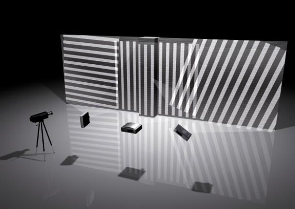
31 P a g e 28 8 Projection Examples with Incorrect Camera Settings A brilliant, error-free projection is the ideal result: Illustration Situation Results Ideal situation: Optimised camera settings, reduced ambient light, camera captures projection completely Best possible rendering of the projected image Some typical camera adjustment errors are listed below. Consult these examples if your results are not satisfactory incorrect camera settings are usually the cause. Illustration Situation Results Incorrect shutter speed setting: In this example, the shutter speed is set to 1/2000. Contrast is too low Widescreen on: The aspect ratio of the camera does not match the aspect ratio of the projector The image width is distorted

32 P a g e 29 Auto focus on: The camera automatically adjusts the focus multiple times during calibration Patterns similar to a mosaic, grainy, frayed edge Automatic white balance (AWB) on: The camera automatically adjusts the aperture multiple times during calibration Image is too bright Automatic exposure: The camera automatically adjusts the sensitivity of the image sensor multiple times during calibration Regular, rastered image errors Camera image is out of focus (manual focus not set to projection surface) Random image distortion, missing parts of the image
33 P a g e 30 9 Contact Information / Help Helpful information and answers related to the VIOSO BlackBox Software from VIOSO are available at You will also find the following: Contact information support Updates Help with activation FAQ based on questions from other users Note: We encourage you to register at the user forum as soon as possible:
1 VIOSO CALIBRATOR manual english VIOSO CALIBRATOR. Autocalibration Software. english version
 1 VIOSO CALIBRATOR manual english VIOSO CALIBRATOR Autocalibration Software english version 2 VIOSO CALIBRATOR manual english Table Of Contents 1. Camera-based Multi Display Setup... 4 1.1. Hardware setup
Fly Elise-ng Grasstrook HG Eindhoven The Netherlands Web: elise-ng.net Tel: +31 (0)
") Fly Elise-ng Grasstrook 24 5658HG Eindhoven The Netherlands Web: http://fly.elise-ng.net Email: info@elise elise-ng.net Tel: +31 (0)40 7114293 Fly Elise-ng Immersive Calibration PRO Step-By Single Camera
Fly Elise-ng Grasstrook 24 5658HG Eindhoven The Netherlands Web: http://fly.elise-ng.net Email: info@elise elise-ng.net Tel: +31 (0)40 7114293 Fly Elise-ng Immersive Calibration PRO Step-By Single Camera
Before you start, make sure that you have a properly calibrated system to obtain high-quality images.
 CONTENT Step 1: Optimizing your Workspace for Acquisition... 1 Step 2: Tracing the Region of Interest... 2 Step 3: Camera (& Multichannel) Settings... 3 Step 4: Acquiring a Background Image (Brightfield)...
Adobe Photoshop. Levels
 How to correct color Once you ve opened an image in Photoshop, you may want to adjust color quality or light levels, convert it to black and white, or correct color or lens distortions. This can improve
XXXX - ILLUSTRATING FROM SKETCHES IN PHOTOSHOP 1 N/08/08
 INTRODUCTION TO GRAPHICS Illustrating from sketches in Photoshop Information Sheet No. XXXX Creating illustrations from existing photography is an excellent method to create bold and sharp works of art
DAVID SLS-1. Getting Started Guide
 DAVID SLS-1 Getting Started Guide Version 3.7 DAVID Vision Systems GmbH Rudolf-Diesel-Str. 2a D-56070 Koblenz Germany Phone: +49(0)261 983 497-70 Fax: +49(0)261 983 497-77 Mail: service@david-vision-systems.de
STAN - The Stereoscopic Analyzer Manual: version Z
 STAN - The Stereoscopic Analyzer Manual: version 2.10-0-1-Z STAN Manual STAN version 2.10-0-1-Z Overview Introduction... 2 First Steps... 3 Select Input Device... 3 Select Input Raster... 4 Adjust Vertical
Leica DMi8A Quick Guide
 Leica DMi8A Quick Guide 1 Optical Microscope Quick Start Guide The following instructions are provided as a Quick Start Guide for powering up, running measurements, and shutting down Leica s DMi8A Inverted
All projected images must be visible from the camera point of view. The content exists in 2D - an "unwrapped" view of the content in the aspect ratio
 How do I calibrate 360 panoramas? You can calibrate cylindrical panoramas using Vioso technology just with one single camera. This can be done by placing the camera with fisheye lens in the center of the
Module 1G: Creating a Circle-Based Cylindrical Sheet-metal Lateral Piece with an Overlaying Lateral Edge Seam And Dove-Tail Seams on the Top Edge
 Inventor (10) Module 1G: 1G- 1 Module 1G: Creating a Circle-Based Cylindrical Sheet-metal Lateral Piece with an Overlaying Lateral Edge Seam And Dove-Tail Seams on the Top Edge In Module 1A, we have explored
Advanced Diploma in. Photoshop. Summary Notes
 Advanced Diploma in Photoshop Summary Notes Suggested Set Up Workspace: Essentials or Custom Recommended: Ctrl Shift U Ctrl + T Menu Ctrl + I Ctrl + J Desaturate Free Transform Filter options Invert Duplicate
Stitching MetroPro Application
 OMP-0375F Stitching MetroPro Application Stitch.app This booklet is a quick reference; it assumes that you are familiar with MetroPro and the instrument. Information on MetroPro is provided in Getting
ISCapture User Guide. advanced CCD imaging. Opticstar
 advanced CCD imaging Opticstar I We always check the accuracy of the information in our promotional material. However, due to the continuous process of product development and improvement it is possible
11 Advanced Layer Techniques
 11 Advanced Layer Techniques After you ve learned basic layer techniques, you can create more complex effects in your artwork using layer masks, path groups, filters, adjustment layers, and more style
Planmeca Romexis. quick guide. Viewer EN _2
 Planmeca Romexis Viewer quick guide EN 10029550_2 TABLE OF CONTENTS 1 START-UP OF PLANMECA ROMEXIS VIEWER...1 1.1 Selecting the interface language... 1 1.2 Selecting images...1 1.3 Starting the Planmeca
G-302 Dual Projector Edge Blender Quick User Guide
 G-302 Dual Projector Edge Blender Quick User Guide Outlook and Functions Procedures for 2 projector edge blending System configuration 1. To use the same projectors and install with the same settings.
Movie Merchandising. Movie Poster. Open the Poster Background.psd file. Open the Cloud.jpg file.
 Movie Poster Open the Poster Background.psd file. Open the Cloud.jpg file. Movie Merchandising Choose Image>Adjustments>Desaturate to make it a grayscale image. Select the Move tool in the Toolbar and
Contents: Bibliography:
 ( 2 ) Contents: Sizing an Image...4 RAW File Conversion...4 Selection Tools...5 Colour Range...5 Quick Mask...6 Extract Tool...7 Adding a Layer Style...7 Adjustment Layer...8 Adding a gradient to an Adjustment
House Design Tutorial
 House Design Tutorial This House Design Tutorial shows you how to get started on a design project. The tutorials that follow continue with the same plan. When you are finished, you will have created a
Drawing with precision
 Drawing with precision Welcome to Corel DESIGNER, a comprehensive vector-based drawing application for creating technical graphics. Precision is essential in creating technical graphics. This tutorial
Android User manual. Intel Education Lab Camera by Intellisense CONTENTS
 Intel Education Lab Camera by Intellisense Android User manual CONTENTS Introduction General Information Common Features Time Lapse Kinematics Motion Cam Microscope Universal Logger Pathfinder Graph Challenge
House Design Tutorial
 House Design Tutorial This House Design Tutorial shows you how to get started on a design project. The tutorials that follow continue with the same plan. When you are finished, you will have created a
Motic Live Imaging Module. Windows OS User Manual
 Motic Live Imaging Module Windows OS User Manual Motic Live Imaging Module Windows OS User Manual CONTENTS (Linked) Introduction 05 Menus, bars and tools 06 Title bar 06 Menu bar 06 Status bar 07 FPS 07
Registering and Distorting Images
 Written by Jonathan Sachs Copyright 1999-2000 Digital Light & Color Registering and Distorting Images 1 Introduction to Image Registration The process of getting two different photographs of the same subject
Kigamo Scanback which fits in your view camera in place of conventional film.
 What's included Kigamo Scanback which fits in your view camera in place of conventional film. SCSI Cable to connect your Scanback to the host computer. A 3-meter SCSI cable is standard. Kigamo also has
How to combine images in Photoshop
 How to combine images in Photoshop In Photoshop, you can use multiple layers to combine images, but there are two other ways to create a single image from mulitple images. Create a panoramic image with
Module 1H: Creating an Ellipse-Based Cylindrical Sheet-metal Lateral Piece
 Inventor (10) Module 1H: 1H- 1 Module 1H: Creating an Ellipse-Based Cylindrical Sheet-metal Lateral Piece In this Module, we will learn how to create an ellipse-based cylindrical sheetmetal lateral piece
Picture Style Editor Ver Instruction Manual
 ENGLISH Picture Style File Creating Software Picture Style Editor Ver. 1.18 Instruction Manual Content of this Instruction Manual PSE stands for Picture Style Editor. In this manual, the windows used in
Contents STARTUP MICROSCOPE CONTROLS CAMERA CONTROLS SOFTWARE CONTROLS EXPOSURE AND CONTRAST MONOCHROME IMAGE HANDLING
 Operations Guide Contents STARTUP MICROSCOPE CONTROLS CAMERA CONTROLS SOFTWARE CONTROLS EXPOSURE AND CONTRAST MONOCHROME IMAGE HANDLING Nikon Eclipse 90i Operations Guide STARTUP Startup Powering Up Fluorescence
Photoshop Elements Hints by Steve Miller
 2015 Elements 13 A brief tutorial for basic photo file processing To begin, click on the Elements 13 icon, click on Photo Editor in the first box that appears. We will not be discussing the Organizer portion
Digital Portable Overhead Document Camera LV-1010
 Digital Portable Overhead Document Camera LV-1010 Instruction Manual 1 Content I Product Introduction 1.1 Product appearance..3 1.2 Main functions and features of the product.3 1.3 Production specifications.4
Table of Contents 1. Image processing Measurements System Tools...10
 Introduction Table of Contents 1 An Overview of ScopeImage Advanced...2 Features:...2 Function introduction...3 1. Image processing...3 1.1 Image Import and Export...3 1.1.1 Open image file...3 1.1.2 Import
Guidance on Using Scanning Software: Part 5. Epson Scan
 Guidance on Using Scanning Software: Part 5. Epson Scan Version of 4/29/2012 Epson Scan comes with Epson scanners and has simple manual adjustments, but requires vigilance to control the default settings
AutoCAD Tutorial First Level. 2D Fundamentals. Randy H. Shih SDC. Better Textbooks. Lower Prices.
 AutoCAD 2018 Tutorial First Level 2D Fundamentals Randy H. Shih SDC PUBLICATIONS Better Textbooks. Lower Prices. www.sdcpublications.com Powered by TCPDF (www.tcpdf.org) Visit the following websites to
Adobe Photoshop CC update: May 2013
 Adobe Photoshop CC update: May 2013 Welcome to the latest Adobe Photoshop CC bulletin update. This is provided free to ensure everyone can be kept upto-date with the latest changes that have taken place
Mullingar Camera Club Basic introduction to Digital Printing using Photoshop CC.
 Mullingar Camera Club Basic introduction to Digital Printing using Photoshop CC. Table of Contents Course aims: 1 Course presentation notes: 1 Introducing Photoshop: 1 Adjusting the Brightness or Contrast
User Manual for HoloStudio M4 2.5 with HoloMonitor M4. Phase Holographic Imaging
 User Manual for HoloStudio M4 2.5 with HoloMonitor M4 Phase Holographic Imaging 1 2 HoloStudio M4 2.5 Software instruction manual 2013 Phase Holographic Imaging AB 3 Contact us: Phase Holographic Imaging
GlassSpection User Guide
 i GlassSpection User Guide GlassSpection User Guide v1.1a January2011 ii Support: Support for GlassSpection is available from Pyramid Imaging. Send any questions or test images you want us to evaluate
Stitching distortion-free mosaic images for QWA using PTGui. Georg von Arx
 Stitching distortion-free mosaic images for QWA using PTGui Georg von Arx Index A. Introduction and overview... 2 B. Taking microscopic images... 2 C. Installing PTGui... 3 D. Initial Setup... 3 E. Preparing
Panoramas and the Info Palette By: Martin Kesselman 5/25/09
 Panoramas and the Info Palette By: Martin Kesselman 5/25/09 Any time you have a color you would like to copy exactly, use the info palette. When cropping to achieve a particular size, it is useful to use
Contents Technical background II. RUMBA technical specifications III. Hardware connection IV. Set-up of the instrument Laboratory set-up
 RUMBA User Manual Contents I. Technical background... 3 II. RUMBA technical specifications... 3 III. Hardware connection... 3 IV. Set-up of the instrument... 4 1. Laboratory set-up... 4 2. In-vivo set-up...
Photoshop CS2. Step by Step Instructions Using Layers. Adobe. About Layers:
 About Layers: Layers allow you to work on one element of an image without disturbing the others. Think of layers as sheets of acetate stacked one on top of the other. You can see through transparent areas
Texture Editor. Introduction
 Texture Editor Introduction Texture Layers Copy and Paste Layer Order Blending Layers PShop Filters Image Properties MipMap Tiling Reset Repeat Mirror Texture Placement Surface Size, Position, and Rotation
STEM Spectrum Imaging Tutorial
 STEM Spectrum Imaging Tutorial Gatan, Inc. 5933 Coronado Lane, Pleasanton, CA 94588 Tel: (925) 463-0200 Fax: (925) 463-0204 April 2001 Contents 1 Introduction 1.1 What is Spectrum Imaging? 2 Hardware 3
Visioneer OneTouch Scanner. Installation Guide FOR WINDOWS
 Visioneer OneTouch Scanner Installation Guide FOR WINDOWS TABLE OF CONTENTS i TABLE OF CONTENTS Getting Started with your new Scanner....................... 1 Step 1: Installing the Scanner Software.......................
Image Processing Tutorial Basic Concepts
 Image Processing Tutorial Basic Concepts CCDWare Publishing http://www.ccdware.com 2005 CCDWare Publishing Table of Contents Introduction... 3 Starting CCDStack... 4 Creating Calibration Frames... 5 Create
Picture Style Editor Ver Instruction Manual
 ENGLISH Picture Style File Creating Software Picture Style Editor Ver. 1.12 Instruction Manual Content of this Instruction Manual PSE is used for Picture Style Editor. In this manual, the windows used
ADD A REALISTIC WATER REFLECTION
 ADD A REALISTIC WATER REFLECTION In this Photoshop photo effects tutorial, we re going to learn how to easily add a realistic water reflection to any photo. It s a very easy effect to create and you can
5. SilverFast Tools Tools SilverFast Manual. 5. SilverFast Tools Image Auto-Adjust (Auto-Gradation) 114
 114") Chapter 5 Tools 5. SilverFast Tools 5. SilverFast Tools 106 5.1 Image Auto-Adjust (Auto-Gradation) 114 5.2 Highlight / Shadow Tool 123 5.3 The Histogram 133 5.4 Gradation Dialogue 147 5.5 Global Colour
Chapter 5 Tools 5. SilverFast Tools 5. SilverFast Tools 106 5.1 Image Auto-Adjust (Auto-Gradation) 114 5.2 Highlight / Shadow Tool 123 5.3 The Histogram 133 5.4 Gradation Dialogue 147 5.5 Global Colour
House Design Tutorial
 Chapter 2: House Design Tutorial This House Design Tutorial shows you how to get started on a design project. The tutorials that follow continue with the same plan. When you are finished, you will have
Using Adobe Photoshop
 Using Adobe Photoshop 4 Colour is important in most art forms. For example, a painter needs to know how to select and mix colours to produce the right tones in a picture. A Photographer needs to understand
ImagesPlus Basic Interface Operation
 ImagesPlus Basic Interface Operation The basic interface operation menu options are located on the File, View, Open Images, Open Operators, and Help main menus. File Menu New The New command creates a
House Design Tutorial
 Chapter 2: House Design Tutorial This House Design Tutorial shows you how to get started on a design project. The tutorials that follow continue with the same plan. When you are finished, you will have
MY ASTROPHOTOGRAPHY WORKFLOW Scott J. Davis June 21, 2012
 Table of Contents Image Acquisition Types 2 Image Acquisition Exposure 3 Image Acquisition Some Extra Notes 4 Stacking Setup 5 Stacking 7 Preparing for Post Processing 8 Preparing your Photoshop File 9
Extending the Dynamic Range of Film
 Written by Jonathan Sachs Copyright 1999-2003 Digital Light & Color Introduction Limited dynamic range is a common problem, especially with today s fine-grained slide films. When photographing contrasty
Horiba LabRAM ARAMIS Raman Spectrometer Revision /28/2016 Page 1 of 11. Horiba Jobin-Yvon LabRAM Aramis - Raman Spectrometer
 Page 1 of 11 Horiba Jobin-Yvon LabRAM Aramis - Raman Spectrometer The Aramis Raman system is a software selectable multi-wavelength Raman system with mapping capabilities with a 400mm monochromator and
Figure 1 The Raith 150 TWO
 RAITH 150 TWO SOP Figure 1 The Raith 150 TWO LOCATION: Raith 150 TWO room, Lithography area, NanoFab PRIMARY TRAINER: SECONDARY TRAINER: 1. OVERVIEW The Raith 150 TWO is an ultra high resolution, low voltage
For customers in USA This device complies with Part 15 of the FCC rules. Operation is subject to the following two conditions:
 User manual For customers in North and South America For customers in USA This device complies with Part 15 of the FCC rules. Operation is subject to the following two conditions: (1) This device may not
Contents Foreword 1 Feedback 2 Legal information 3 Getting started 4 Installing the correct Capture One version 4 Changing the version type 5 Getting
 Contents Foreword 1 Feedback 2 Legal information 3 Getting started 4 Installing the correct Capture One version 4 Changing the version type 5 Getting to know Capture One Pro 6 The Grand Overview 6 The
Edge Blender Controller
 Edge Blender Controller Calibration Manual Version 2017 V1 Contents Contents INTRODUCTION 1 FEATURES 1 OS AND HARDWARE 1 INSTALLATION 2 INSTALLATION 2 UNINSTALLATION 4 INTERFACE 6 COMMUNICATION 7 CONFIG
Chlorophyll Fluorescence Imaging System
 Quick Start Guide Chlorophyll Fluorescence Imaging System Quick Start Guide for Technologica FluorImager software for use with Technlogica CFImager hardware Copyright 2006 2015 TECHNOLOGICA LIMITED. All
G-700 multiple Channel 4K Curve Edge Blending Processor
 G-700 multiple Channel 4K Curve Edge Blending Processor G-700 is a curved screen edge blending processor with the ability to provide multiple processing modules to control from 1 to 4 projectors based
Color and More. Color basics
 Color and More In this lesson, you'll evaluate an image in terms of its overall tonal range (lightness, darkness, and contrast), its overall balance of color, and its overall appearance for areas that
CALIBRATION MANUAL. Version Author: Robbie Dowling Lloyd Laney
 Version 1.0-1012 Author: Robbie Dowling Lloyd Laney 2012 by VirTra Inc. All Rights Reserved. VirTra, the VirTra logo are either registered trademarks or trademarks of VirTra in the United States and/or
Adobe Photoshop CS5 Layers and Masks
 Adobe Photoshop CS5 Layers and Masks Email: training@health.ufl.edu Web Page: http://training.health.ufl.edu Adobe Photoshop CS5: Layers and Masks 2.0 Hours The workshop will cover creating and manipulating
Workflow for Betterlight Imaging
 Workflow for Betterlight Imaging [1] Startup Check that camera lens shutter is fully open Check lens is set to F stop 11 (change by manually adjusting lens aperture ring) Check Infrared (IR) Absorbing
Technical Note How to Compensate Lateral Chromatic Aberration
 Lateral Chromatic Aberration Compensation Function: In JAI color line scan cameras (3CCD/4CCD/3CMOS/4CMOS), sensors and prisms are precisely fabricated. On the other hand, the lens mounts of the cameras
Roof Tutorial Wall Specification
 Roof Tutorial The majority of Roof Tutorial describes some common roof styles that can be created using settings in the Wall Specification dialog and can be completed independent of the other tutorials.
Brightness and Contrast Control Reference Guide
 innovation Series Scanners Brightness and Contrast Control Reference Guide A-61506 Part No. 9E3722 CAT No. 137 0337 Using the Brightness and Contrast Control This Reference Guide provides information and
Picture Style Editor Ver Instruction Manual
 ENGLISH Picture Style File Creating Software Picture Style Editor Ver. 1.15 Instruction Manual Content of this Instruction Manual PSE stands for Picture Style Editor. indicates the selection procedure
Creo Revolve Tutorial
 Creo Revolve Tutorial Setup 1. Open Creo Parametric Note: Refer back to the Creo Extrude Tutorial for references and screen shots of the Creo layout 2. Set Working Directory a. From the Model Tree navigate
Digital Imaging - Photoshop
 Digital Imaging - Photoshop A digital image is a computer representation of a photograph. It is composed of a grid of tiny squares called pixels (picture elements). Each pixel has a position on the grid
Learning Guide. ASR Automated Systems Research Inc. # Douglas Crescent, Langley, BC. V3A 4B6. Fax:
 Learning Guide ASR Automated Systems Research Inc. #1 20461 Douglas Crescent, Langley, BC. V3A 4B6 Toll free: 1-800-818-2051 e-mail: support@asrsoft.com Fax: 604-539-1334 www.asrsoft.com Copyright 1991-2013
MAKE SURE YOUR SLIDES ARE CLEAN (TOP & BOTTOM) BEFORE LOADING DO NOT LOAD SLIDES DURING SOFTWARE INITIALIZATION
 BEFORE LOADING DO NOT LOAD SLIDES DURING SOFTWARE INITIALIZATION") Olympus VS120-L100 Slide Scanner Standard Operating Procedure Startup 1) Red power bar switch (behind monitor) 2) Computer 3) Login: UserVS120 account (no password) 4) Double click: WAIT FOR INITIALIZATION
Olympus VS120-L100 Slide Scanner Standard Operating Procedure Startup 1) Red power bar switch (behind monitor) 2) Computer 3) Login: UserVS120 account (no password) 4) Double click: WAIT FOR INITIALIZATION
[Use Element Selection tool to move raster towards green block.]
![[Use Element Selection tool to move raster towards green block.]](/thumbs/71/65972197.jpg "[Use Element Selection tool to move raster towards green block.]") Demo.dgn 01 High Performance Display Bentley Descartes has been designed to seamlessly integrate into the Raster Manager and all tool boxes, menus, dialog boxes, and other interface operations are consistent
Demo.dgn 01 High Performance Display Bentley Descartes has been designed to seamlessly integrate into the Raster Manager and all tool boxes, menus, dialog boxes, and other interface operations are consistent
inphoto ID SLR Automatic ID photography With Canon SLR camera User Guide
 inphoto ID SLR Automatic ID photography With Canon SLR camera User Guide 2014 Akond company Phone/fax: +7(812)384-6430 Cell: +7(921)757-8319 e-mail: info@akond.net akondsales@gmail.com http://www.akond.net
ACDSee Pro 3 tutorials: Process mode overview
 ACDSee Pro 3 tutorials: Process overview After you have organized and viewed your images in Manage and View s, you are ready to take your images into Process for developing and editing. Start in to do
T I P S F O R I M P R O V I N G I M A G E Q U A L I T Y O N O Z O F O O T A G E
 T I P S F O R I M P R O V I N G I M A G E Q U A L I T Y O N O Z O F O O T A G E Updated 20 th Jan. 2017 References Creator V1.4.0 2 Overview This document will concentrate on OZO Creator s Image Parameter
Lucida 3D Scanner Factum Foundation
 Factum Foundation Training guide II: factumfoundation.org Table of contents 4 The user interface How to attach the calibration tool Calibration Settings System settings Camera settings. Movement Planning
Adobe Photoshop CS5 ACE
 Adobe Photoshop CS5 ACE Number: A9A0-150 Passing Score: 800 Time Limit: 120 min File Version: 1.0 Sections 1. Selection Tools Exam A QUESTION 1 John creates a circular selection with Elliptical Marquee
User Guide for TWAIN / DirectX interface for GRYPHAX USB 3.0 cameras
 User Guide for TWAIN / DirectX interface for GRYPHAX USB 3.0 cameras The TWAIN & DirectX driver for PROGRES GRYPHAX USB 3.0 cameras enables user to operate with TWAIN and DirectX supported 3 rd party software
EAN-Blending. PN: EAN-Blending 11/30/2017. SightLine Applications, Inc.
 PN: EAN-Blending 11/30/2017 SightLine Applications, Inc. Contact: Web: sightlineapplications.com Sales: sales@sightlineapplications.com Support: support@sightlineapplications.com Phone: +1 (541) 716-5137
Marshall Electronics. Full-HD (3G/HD-SDI) Mini-Broadcast POV Cameras. CV343, CV502, CV345, CV505 models. Operation Manual
 Mini-Broadcast POV Cameras. CV343, CV502, CV345, CV505 models. Operation Manual") Marshall Electronics Full-HD (3G/HD-SDI) Mini-Broadcast POV Cameras CV343, CV502, CV345, CV505 models Operation Manual STRUCTURE SETUP WB CTROL SUB DC IRIS ATW PUSH BRIGHTNESS AGC LIMIT AE CTROL (EXPOSURE)
Marshall Electronics Full-HD (3G/HD-SDI) Mini-Broadcast POV Cameras CV343, CV502, CV345, CV505 models Operation Manual STRUCTURE SETUP WB CTROL SUB DC IRIS ATW PUSH BRIGHTNESS AGC LIMIT AE CTROL (EXPOSURE)
prepared by Allison Hwang for T. Purdy 2011
 This tutorial shows you how to create a basic screen display on a product in Adobe Photoshop. Creating details, such as shadows and reflections, can help make your product more realistic and convincing
User Guide of ISCapture
 User Guide of ISCapture For Windows2000/XP/Vista(32bit/64bit)/Win7(32bit/64bit) Xintu Photonics Co., Ltd. Version: 2.6 I All the users of Xintu please kindly note that the information and references in
CHAPTER1: QUICK START...3 CAMERA INSTALLATION... 3 SOFTWARE AND DRIVER INSTALLATION... 3 START TCAPTURE...4 TCAPTURE PARAMETER SETTINGS... 5 CHAPTER2:
 Image acquisition, managing and processing software TCapture Instruction Manual Key to the Instruction Manual TC is shortened name used for TCapture. Help Refer to [Help] >> [About TCapture] menu for software
IncuCyte ZOOM Fluorescent Processing Overview
 IncuCyte ZOOM Fluorescent Processing Overview The IncuCyte ZOOM offers users the ability to acquire HD phase as well as dual wavelength fluorescent images of living cells producing multiplexed data that
Adobe Photoshop CC 2018 Tutorial
 Adobe Photoshop CC 2018 Tutorial GETTING STARTED Adobe Photoshop CC 2018 is a popular image editing software that provides a work environment consistent with Adobe Illustrator, Adobe InDesign, Adobe Photoshop,
Alternatively, the solid section can be made with open line sketch and adding thickness by Thicken Sketch.
 Sketcher All feature creation begins with two-dimensional drawing in the sketcher and then adding the third dimension in some way. The sketcher has many menus to help create various types of sketches.
Rendering a perspective drawing using Adobe Photoshop
 Rendering a perspective drawing using Adobe Photoshop This hand-out will take you through the steps to render a perspective line drawing using Adobe Photoshop. The first important element in this process
Module 1C: Adding Dovetail Seams to Curved Edges on A Flat Sheet-Metal Piece
 1 Module 1C: Adding Dovetail Seams to Curved Edges on A Flat Sheet-Metal Piece In this Module, we will explore the method of adding dovetail seams to curved edges such as the circumferential edge of a
House Design Tutorial
 Chapter 2: House Design Tutorial This House Design Tutorial shows you how to get started on a design project. The tutorials that follow continue with the same plan. When we are finished, we will have created
CONTENT INTRODUCTION BASIC CONCEPTS Creating an element of a black-and white line drawing DRAWING STROKES...
 USER MANUAL CONTENT INTRODUCTION... 3 1 BASIC CONCEPTS... 3 2 QUICK START... 7 2.1 Creating an element of a black-and white line drawing... 7 3 DRAWING STROKES... 15 3.1 Creating a group of strokes...
AgilEye Manual Version 2.0 February 28, 2007
 AgilEye Manual Version 2.0 February 28, 2007 1717 Louisiana NE Suite 202 Albuquerque, NM 87110 (505) 268-4742 support@agiloptics.com 2 (505) 268-4742 v. 2.0 February 07, 2007 3 Introduction AgilEye Wavefront
Reikan FoCal Aperture Sharpness Test Report
 Focus Calibration and Analysis Software Test run on: 26/01/2016 17:02:00 with FoCal 2.0.6.2416W Report created on: 26/01/2016 17:03:39 with FoCal 2.0.6W Overview Test Information Property Description Data
Learning Photo Retouching techniques the simple way
 Learning Photo Retouching techniques the simple way Table of Contents About the Workshop... i Workshop Objectives... i Getting Started... 1 Photoshop Workspace... 1 Setting up the Preferences... 2 Retouching
AutoCAD LT 2012 Tutorial. Randy H. Shih Oregon Institute of Technology SDC PUBLICATIONS. Schroff Development Corporation
 AutoCAD LT 2012 Tutorial Randy H. Shih Oregon Institute of Technology SDC PUBLICATIONS www.sdcpublications.com Schroff Development Corporation AutoCAD LT 2012 Tutorial 1-1 Lesson 1 Geometric Construction
Introduction to CATIA V5
 Introduction to CATIA V5 Release 17 (A Hands-On Tutorial Approach) Kirstie Plantenberg University of Detroit Mercy SDC PUBLICATIONS Schroff Development Corporation www.schroff.com Better Textbooks. Lower
Extreme Makeovers: Photoshop Retouching Techniques
 Extreme Makeovers: Table of Contents About the Workshop... 1 Workshop Objectives... 1 Getting Started... 1 Photoshop Workspace... 1 Retouching Tools... 2 General Steps... 2 Resolution and image size...
Key Terms. Where is it Located Start > All Programs > Adobe Design Premium CS5> Adobe Photoshop CS5. Description
 Adobe Adobe Creative Suite (CS) is collection of video editing, graphic design, and web developing applications made by Adobe Systems. It includes Photoshop, InDesign, and Acrobat among other programs.