MRF and Subaperture Stitching: manufacture and measure more optics, more accurately
|
|
|
- Sophia Bryan
- 5 years ago
- Views:
Transcription

1 MRF and Subaperture Stitching: manufacture and measure more optics, more accurately Presented By: Jean Pierre Lormeau QED European Business Manager QED Technologies International Inc. October, 2012


2 Presentation topics MRF: A Little History MRF general principles and benefits Examples of applications Stitching Interferometry Motivation General principles Spheres Aspheres Examples of applications


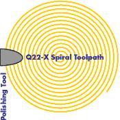
3 Early Evolution of MRF From R&D to Commercial Product QED Q22 Prototype COM Prototype 1996 COM Trough Machine 1993 QED Q22-X/Y Copyright QED Technologies 2012 October,, 2012


4 MRF Platform Portfolio Evolution to Larger Optics ~2000 mm ~100 mm ~200 mm ~1000 mm ~400 mm ~750 mm Copyright QED Technologies 2012 October,, 2012

5 Magnetorheological Finishing (MRF ) What is MRF? Very deterministic polishing & figuring technology MRF tool is stable, conformable & predictable w/ high peak removal rates Part Ø from ~5 mm to ~2 m Multi-axis CNC machine bases Rotational polishing Raster polishing Tool is based on fluid Conforms perfectly to any shape Fluid can be monitored & maintained Fluid changes viscosity in magnetic field Stiffened near optic to create high shear removal function High automated, metrologydriven process


6 How MRF Works Random arrangement of particles Field creates stiff structure of iron particles Forces water and abrasives to top, thin layer Converging gap is created Cores are formed, creating sheared layer of fluid Pressure gradient is formed High-velocity, shear-based removal is created Unsheared Fluid Abrasive Particles Iron Particles Wheel Rotation 6


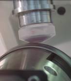
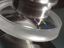
7 Schematic of MR Finishing Interface MRF Spot Creation Lens Moving Wall MR Fluid Contact zone Removal spot Copyright QED Technologies 2012 October,, 2012
8 How MRF works Forces acting in polishing Conventional Polishing MRF Abrasive Particle 1-2 m Pad Load Workpiece Workpiece Hydrostatic Pressure m Magnetic buoyant force MR Fluid Core An abrasive particle is embedded in a rigid pad, which supports the particle load. The normal force (~0.01 N) is significant enough to cause surface indentation and scratching. Because the particle/surface contact area is small, the hydrostatic pressure results in insignificant normal force (~10-7 N). The buoyant force (~10-9 N) is also too small to cause appreciable indentation. 8 Copyright QED Technologies 2012 October,, 2012


9 Understanding Potential for Corrosion Specific surface area of iron particles ~ 1m 2 /g Surface area of iron particles in 1 liter of MR fluid ~ 4000 m 2 Surface area of a football field = 5500 m 2 The surface of iron particles is constantly attacked by abrasive particles resulting in intensive erosion and corrosion.
10 MR Polishing Fluid Composition The stabilizer is a key element in MR fluid development. It helps to resolve a contradiction between requirement high concentration of iron particles low fluid viscosity. Also, it is responsible for fluid sedimentation stability, redispersability, corrosion control Iron particles Stabilizer Water Abrasive
11 Roughness, Rq (Angstrom) Family of Aqueous MR Polishing Fluids 6 QED Fluids Performance 5 D-10 4 C-10+ D-11 Material FS BK D-20 AIM TREND CaF Si Peak Removal Rate (um/min) With one charge of fluid removal rate stability is provided for at least 3 weeks
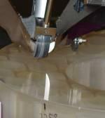
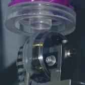
12 How MRF works Fluid delivery system MRF Delivery system is heart of machine Creates stable, continuous, flow of MR fluid Lens Nozzle Suction Wheel Pump Electromagnet Pump MR fluid conditioner 12 Copyright QED Technologies 2012 October,, 2012
13 MRF Removal mechanism summary: Shear stress creates material removal! MRF is fluid based MR Fluid properties are precisely controlled MRF tool is subaperture The MRF subaperture tool is insensitive to Z-Axis errors MRF material removal mechanism is based on shear stress MRF end result is predicted and achieved Copyright QED Technologies 2012 October,, 2012


14 What Can MRF Do? MRF has many uses Improve form/figure/waveform High convergence 5-10x improvement in 1 iteration l/20, l/50 as good as your metrology Improve roughness Typically ~ 0.5 nm RMS Improve surface integrity Remove subsurface damage Remove stress Increase laser damage resistance


15 Examples of MRF applications Large Face Sheet 300mm Si Wafers Shear Plate TWF Correction Dove Prisms Steep Concave Laser Rods Lightweight Primary Mirror Lightweight SiC Mirror Meter-Class Aspheres Novel Geometries Steep Aspheres High Aspect Ratio Optics Calcium Fluoride Sapphire Windows Off-axis Zerodur Component
16 Optics Fabrication Options Where does MRF fit in? Molding Glass/Plastic Molding Grinding Aspheric Grinding SPDT Single Point Diamond Turning (SPDT) CCP Computer Controlled Polishing (CCP) Magnetorheological Finishing (MRF) MRF IBF Ion Beam Finishing (IBF) Blank Near Net Shape Precision Optic High Precision Optic


17 Typical correction of form error Polishing Material: Borofloat C-10+ fluid 50mm wheel 2mm edge exclusion 2 Runs 50 mm convex sphere, RC 99,96. Boro Glass Figure < λ/10 over full aperture (PV = wv) Figure < λ/20 over 49 mm (PV = 0.044wv, 0.5 mm edge exclusion) 17

18 Convex CaF 2 Sphere F ~ 25 mm, R ~ 310 mm Before MRF Final Figure PV = wave RMS = wave 4 Iterations, 20 min PV = wave RMS = wave


19 10 mm phase correctors, create a perfectly bad surface Desired Figure Actual Figure Difference Map 2.6 μm PV 818 nm rms 2.6 μm PV 811 nm rms 50 nm PV, 9 nm rms


20 Example Rod Correction Transmitted wavefront improved by ~9x MRF offers robust, reliable process for correcting material inhomogeneities Before After MRF correction TWF PV = 0.44l TWF PV = 0.05l 20

21 Corrected rods dramatically improve laser performance Improvement in far field intensity distribution of CLARA laser system MRF induced perfectly bad surface on single rod face to compensate for inhomogeneity System divergence went from unusable to nearly diffraction limited 21 Copyright QED Technologies 2012 October,, 2012


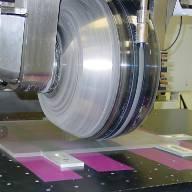
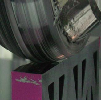
22 NIF Continuous Phase Plates (CPP) Capability Unique to MRF Computer generated topographical profiles are designed to achieve required energy contours for laser beam 430x430 mm fused silica plates with mountains & valleys microns high and mm-cm wide A good example of a perfectly bad surface that MRF can help make Copyright QED Technologies 2012 October,, 2012

 Initial polishing with large")


23 CPP Imprinting Process Step #1 Large Spot Low order imprinting 150 mm square sample (~1/3 x 1/3 of a whole plate) Initial polishing with large wheel imprints lower order error High removal rate roughs out the CPP pattern Tool size: ~30 mm Up to 6 m of removal in some locations on the surface Before Target Result Big Spot 23 Copyright QED Technologies 2012 October,, 2012


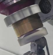
24 CPP Imprinting Process Step #2 Small Spot Imprinting the fine features Final Polishing with small wheel imprints higher order error, tool size: ~3-4 mm Before Target Result Small Spot 2.4x zoom
 Inner Diameter: ~0.")
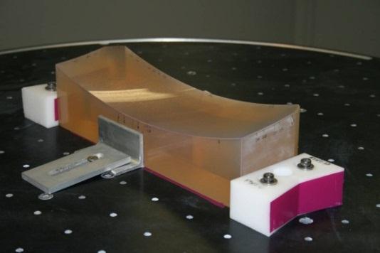
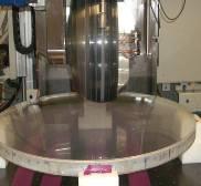
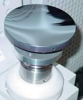
25 Q F: Meter-class figure correction MRF polishing of primary mirror Mirror Details Outer Diameter: ~1.1 m (~43 ) Inner Diameter: ~0.1 m (~4 ) Concave Radius of Curvature: ~3 m (~120 ) Material: Zerodur-like


 Fast Convergence on")
26 Q F: Meter-class figure correction Only 20 hours of polishing time Only 2 iterations of MRF Initial Final RMS = 80 nm (~l/7) RMS = 9 nm (~l/70) Fast Convergence on Meter-Class Optics!


27 SPDT + MRF SPDT MRF Figure Correction Grinding Molding SPDT CCP 2-step process only MRF Fully Deterministic IBF For Turnable materials E.g. higher precision IR Blank Near Net Shape Precision Optic High Precision Optic

28 Concave SPDT Si Sphere F ~ 17 mm, R ~ 20 mm Before MRF Figure After 1 iteration S/N min Before MRF Figure After 1 iteration S/N min


29 MRF Removes the Diamond Turning Marks Before MRF After MRF Color No Color


30 Latest MRF Development Q-flex MRF Platform Modular Production oriented Flexible optics production Plano, Sphere, Asphere, Cylinder, prism Freeform
31 Motivation for Sub-aperture Stitching Interferometry If you can t measure it, you can t make it Corollary: the quality and flexibility of your measurement limits the quality and variety of optical surface you can make particularly if you have an exceptional deterministic polishing tool at hand And therefore we want our metrology to be: Full aperture, for deterministic correction of the whole surface Accurate, to achieve tighter optical specifications High resolution, to correct edges and other small features Flexible, to minimize custom tooling and lead time even for aspheres Subaperture stitching can address all these needs


32 Scale: PV l/10 Full vs. sub aperture metrology Myth #1: If all subapertures pass spec, the full aperture passes Subaperture QA may be appropriate for a few applications Full aperture metrology necessary for deterministic finishing and quality insurance Stitched Full aperture PV 81 rms 10.2 Full aperture fails l/10 PV, l/100 rms specification On axis Subapertures (all pass a l/10 PV, l/100 rms spec) Off-center (up) Off-center (right) PV 34 rms 5.7 PV 38 rms 4.5 PV 44 rms 5.4


33 Are you measuring what you think you are? Myth #2: if the measurement is l/10, the part is l/10 full aperture mismatch reference PV 48 rms 8.3 Two-sphere calibration PV 26 rms 2.0 Difference from SSI reference


34 QED Stitching History QED has successfully developed subaperture stitching interferometry for a variety of uses: 2004: SSI for large aperture spheres/flats 2007: SSI-A for mild aspheres without null lenses 2009: ASI for high-departure aspheres without null lenses


35 Subaperture Stitching systems Precision Multi-axis motion control platform SSI-A and ASI w/o VON: ASI: 4 or 6 interferometer 6 axes 11 axes QED control software: automation + advanced algorithms + Variable Optical Null technology Stitching advantages Cost-effective measurement of larger optics, full aperture Automatic, inline calibration of systematic error Increased lateral resolution Measures aspheres without dedicated nulls!
36 SSI & ASI measurement process for spheres Specify surface to test transmission sphere Select transmission sphere and define lattice Locate central null Move to lattice position Auto-null Measure full aperture mismatch reference Stitch Fully automated process

 NA: 1 (90º) NA: 1.")
 Ø 300 mm Large clear aperture Ø 225 mm 200")


37 The SSI & ASI measure spherical parts that a 6 interferometer cannot test Large numerical aperture Ø 36 mm R -18 mm Ø 36 mm R 18 mm Ø 9 mm R 4.5 mm Ø 59 mm R 30 mm NA: 1 (90º) NA: 1 (90º) NA: 1.0 (90º) NA: 0.98 (79º) Ø 300 mm Large clear aperture Ø 225 mm " TF 6" f/7.2 6" f/5.3 Higher CA 6" f/3.2 6" f/2.2 6" f/1.1 6" f/0.77 conventional capability 4" interferometer 6" interferometer SSI capability 4" recommended 6" recommended Higher NA R 350 mm R 350 mm " TF flat 4" f/11 4" f/ " f/3.3 4" f/ radius of curvature (mm) 50 4" f/ Copyright QED Technologies 2012 October,, 2012
38 Aspheric testing State of the art with out stitching interferometer null test Standard methods require dedicated test optics to be made Computer-generated hologram (CGH) Refractive, or sometimes reflective, null Disadvantages: Lead time, cost, accuracy, and convex parts Stitching employs a non-null test for aspheres Flexible: no dedicated null optics needed! Current ASI capability up to ~650 micrometer of departure from best fit sphere More possible as QED continues to develop the technology


39 What is a non-null test? The reference wavefront does not match the surface A perfect surface produces fringes in a non-null test Test rays will not trace back on themselves retrace error Transmission sphere NulI test: sphere NulI test: asphere Non-nulI test Surface under test


40 SSI-A The first solution for aspheres No null optics required!! Testing a hyperboloid


 Asphere w/ ~80 l departure from bfs (~320 l from vertex")
41 Increasing measurable aspheric departure: how does it work? Three key issues to address Fringe resolution use slower TSs (higher magnification) & stitch Retrace error automatically model and compensate w/ stitching Remove nominal shape precise motion + auto-compensation f/0.75 f/3.3 (~4x) Asphere w/ ~80 l departure from bfs (~320 l from vertex sphere) Copyright QED Technologies 2012 October,, 2012 BFS


42 SSI-A example & cross test with CGH R -310 mm; CA 110 mm; ~30 l from bfs. 33 subapertures (10-15 minutes) w/ f/3.2 TS Good agreement with CGH cross test but higher resolution & easier calibration! CGH test Stitch map (+lattice) subapertures Stitch map 64 61


43 SSI-A example (2) R 226 mm; CA 100 mm; ~25 l from bfs. Secondary mirror for the PICTURE / SHARPI sounding rocket programs Good agreement with vendor s null test But again, note the finer structure resolved Null test data courtesy of Jay Schwartz, L3- SSG-Tinsley Conic null test Stitch map 3.3 Scale +/ nm Test part courtesy of Scott Antonille, NASA Goddard 4.4


44 ASI: Variable Optical Null Device Interferometer Asphere Interferometer Variable Optical Null device


45 Our Particular VON Counter-rotating optical wedges Plane-parallel Maximum wedge By varying the total wedge angle and tilt, the VON produces loworder aberrations: Astigmatism, coma, trefoil Flat surfaces only, simple mechanical motions


46 Variable Optical Null Configurations No Tilt No Wedge Tilt only Wedge only Tilt and Wedge small spherical mostly astigmatism mostly coma coma and astigmatism


47 Sub-aps with or without VON With VON Without VON


48 1000 Wave Asphere Example 118 mm CA 72 mm vertex radius 656 micron departure from best fit sphere High NA and aspheric departure make this asphere difficult to measure with other techniques


49 Impact of the VON on the example SSI W/O VON With VON R = 0 mm R = 16 mm R = 31 mm R = 46 mm Only need to match the low-order aberrations of each subaperture, producing resolvable fringes over entire field Combine measurement of residuals with nominal wavefront of VON


50 Subaperture Measurements Simulated Measured R = 16 mm R = 31 mm R = 46 mm Actual subaperture measurements show good agreement with model (small differences due to alignment, figure error on part) Use stitching algorithms to refine the nominal wavefront


51 Example of High Resolution Stitch 2k x 2k stitch 2.6 million pixels! Center 10mm (data refitted)

52 Lateral Resolution Comparison Center 10mm aperture with 36 Zernike terms removed 400 x 400 pixel stitch 2000 x 2000 pixel stitch


53 Lateral Resolution Comparison 10mm aperture offset by 15mm, with 36 Zernike terms removed 400 x 400 pixel stitch 2000 x 2000 pixel stitch


54 Results with MRF Correction Part had low figure error, but high mid-spatial frequency content ASI + MRF successful at measuring and improving the surface Initial condition (rms = 7.4nm) After single MRF correction (rms = 2.6nm)
55 Conclusion The use of subaperture stitching interferometry allows for: Full aperture coverage on 200 mm+ lenses Higher lateral resolution Increased accuracy Aspheric measurements without dedicated nulls up to 1000 waves of departure from best fit sphere for the ASI Combining Subaperture Metrology capability with the unique efficiency and performance of MRF provides unmatch capabilities both in R&D and production
FLEXIBLE POLISHING AND METROLOGY SOLUTIONS FOR FREE-FORM OPTICS
 FLEXIBLE POLISHING AND METROLOGY SOLUTIONS FOR FREE-FORM OPTICS Paul R. Dumas, Jon Fleig, Greg W. Forbes, Don Golini, William I. Kordonski, Paul E. Murphy, Aric B. Shorey, Marc Tricard QED Technologies,
High Spatial Resolution Metrology using Sub-Aperture Stitching
 High Spatial Resolution Metrology using Sub-Aperture Stitching Stephen O Donohue, Paul Murphy and Marc Tricard 1040 University Avenue, Rochester, NY USA +1 (585) 256-6540 tricard@qedmrf.com www.qedmrf.com
Aspheric Lenses. Contact us for a Stock or Custom Quote Today! Edmund Optics BROCHURE
 Edmund Optics BROCHURE Aspheric Lenses products & capabilities Contact us for a Stock or Custom Quote Today! USA: +1-856-547-3488 EUROPE: +44 (0) 1904 788600 ASIA: +65 6273 6644 JAPAN: +81-3-3944-6210
Fabrication of 6.5 m f/1.25 Mirrors for the MMT and Magellan Telescopes
 Fabrication of 6.5 m f/1.25 Mirrors for the MMT and Magellan Telescopes H. M. Martin, R. G. Allen, J. H. Burge, L. R. Dettmann, D. A. Ketelsen, W. C. Kittrell, S. M. Miller and S. C. West Steward Observatory,
Fabrication and testing of large free-form surfaces Jim H. Burge
 Fabrication and testing of large free-form surfaces Jim H. Burge College of Optical Sciences + Steward Observatory University of Arizona Tucson, AZ 85721 Introduction A tutorial on Fabrication and testing
Difrotec Product & Services. Ultra high accuracy interferometry & custom optical solutions
 Difrotec Product & Services Ultra high accuracy interferometry & custom optical solutions Content 1. Overview 2. Interferometer D7 3. Benefits 4. Measurements 5. Specifications 6. Applications 7. Cases
Developments in Precision Asphere Manufacturing Jay Tierson, Ed Fess, Greg Mathews OptiPro Systems LLC, 6368 Dean Parkway, Ontario NY 14519
 Developments in Precision Asphere Manufacturing Jay Tierson, Ed Fess, Greg Mathews OptiPro Systems LLC, 6368 Dean Parkway, Ontario NY 14519 ABSTRACT The increased use of aspheres in today s optical systems
Computer Generated Holograms for Optical Testing
 Computer Generated Holograms for Optical Testing Dr. Jim Burge Associate Professor Optical Sciences and Astronomy University of Arizona jburge@optics.arizona.edu 520-621-8182 Computer Generated Holograms
The Design, Fabrication, and Application of Diamond Machined Null Lenses for Testing Generalized Aspheric Surfaces
 The Design, Fabrication, and Application of Diamond Machined Null Lenses for Testing Generalized Aspheric Surfaces James T. McCann OFC - Diamond Turning Division 69T Island Street, Keene New Hampshire
CONFORMAL OGIVE ALON DOME FABRICATION
 16 September 2004 TECHNOLOGY DEMONSTRATION BRIEF CONFORMAL OGIVE ALON DOME FABRICATION Keywords: Conformal, freeform, optics, ogive, ALON, domes, near-net-shape castings, infrared transmitting ceramics
Designing and Specifying Aspheres for Manufacturability
 Designing and Specifying Aspheres for Manufacturability Jay Kumler Coastal Optical Systems Inc 4480 South Tiffany Drive, West Palm Beach, FL 33407 * ABSTRACT New technologies for the fabrication of aspheres
Testing an off-axis parabola with a CGH and a spherical mirror as null lens
 Testing an off-axis parabola with a CGH and a spherical mirror as null lens Chunyu Zhao a, Rene Zehnder a, James H. Burge a, Hubert M. Martin a,b a College of Optical Sciences, University of Arizona 1630
Testing Aspheric Lenses: New Approaches
 Nasrin Ghanbari OPTI 521 - Synopsis of a published Paper November 5, 2012 Testing Aspheric Lenses: New Approaches by W. Osten, B. D orband, E. Garbusi, Ch. Pruss, and L. Seifert Published in 2010 Introduction
A fast F-number 10.6-micron interferometer arm for transmitted wavefront measurement of optical domes
 A fast F-number 10.6-micron interferometer arm for transmitted wavefront measurement of optical domes Doug S. Peterson, Tom E. Fenton, Teddi A. von Der Ahe * Exotic Electro-Optics, Inc., 36570 Briggs Road,
Manufacturing, testing and alignment of Sentinel-2 MSI telescope mirrors
 Manufacturing, testing and alignment of Sentinel-2 MSI telescope mirrors P. Gloesener, F. Wolfs, F. Lemagne, C. Flebus AMOS Angleur, Belgium pierre.gloesener@amos.be P. Gloesener, F. Wolfs, F. Lemagne,
Fizeau interferometer with spherical reference and CGH correction for measuring large convex aspheres
 Fizeau interferometer with spherical reference and CGH correction for measuring large convex aspheres M. B. Dubin, P. Su and J. H. Burge College of Optical Sciences, The University of Arizona 1630 E. University
3.0 Alignment Equipment and Diagnostic Tools:
 3.0 Alignment Equipment and Diagnostic Tools: Alignment equipment The alignment telescope and its use The laser autostigmatic cube (LACI) interferometer A pin -- and how to find the center of curvature
Asphere and Freeform Measurement 101
 OptiPro Systems Ontario, NY, USA Asphere and Freeform Measurement 101 Asphere and Freeform Measurement 101 By Scott DeFisher This work culminates the previous Aspheric Lens Contour Deterministic Micro
Optical Engineering 421/521 Sample Questions for Midterm 1
 Optical Engineering 421/521 Sample Questions for Midterm 1 Short answer 1.) Sketch a pechan prism. Name a possible application of this prism., write the mirror matrix for this prism (or any other common
Manufacture of 8.4 m off-axis segments: a 1/5 scale demonstration
 Manufacture of 8.4 m off-axis segments: a 1/5 scale demonstration H. M. Martin a, J. H. Burge a,b, B. Cuerden a, S. M. Miller a, B. Smith a, C. Zhao b a Steward Observatory, University of Arizona, Tucson,
Why is There a Black Dot when Defocus = 1λ?
 Why is There a Black Dot when Defocus = 1λ? W = W 020 = a 020 ρ 2 When a 020 = 1λ Sag of the wavefront at full aperture (ρ = 1) = 1λ Sag of the wavefront at ρ = 0.707 = 0.5λ Area of the pupil from ρ =
Aspheres and freeforms
 Aspheres and freeforms Historically, the disadvantages of poor manufacturability and metrology determined the choice of using classical optics for optomechanical instrumentation. Worldwide however, a lot
Design and Manufacture of 8.4 m Primary Mirror Segments and Supports for the GMT
 Design and Manufacture of 8.4 m Primary Mirror Segments and Supports for the GMT Introduction The primary mirror for the Giant Magellan telescope is made up an 8.4 meter symmetric central segment surrounded
CORRECTOR LENS FOR THE PRIME FOCUS OF THE WHT
 IAC TECHNOLOGY DIVISION DM/SR-WEA/023 AD1. Procurement technical specifications for L4.doc 17 de junio de 2015 PROJECT / DESTINATION: CORRECTOR LENS FOR THE PRIME FOCUS OF THE WHT TITLE: PROCUREMENT TECHNICAL
LuphoScan platforms. Dr. Gernot Berger (Business Development Manager) APOMA Meeting, Tucson, years of innovation
 APOMA Meeting, Tucson, years of innovation") 125 years of innovation (Business Development Manager) APOMA Meeting, Tucson, 2016 HQ in Berwyn, Pennsylvania $4.0 billion in sales (2015) 15,000 colleagues, 150 manufacturing locations, 30 countries Businesses
125 years of innovation (Business Development Manager) APOMA Meeting, Tucson, 2016 HQ in Berwyn, Pennsylvania $4.0 billion in sales (2015) 15,000 colleagues, 150 manufacturing locations, 30 countries Businesses
Optical Components for Laser Applications. Günter Toesko - Laserseminar BLZ im Dezember
 Günter Toesko - Laserseminar BLZ im Dezember 2009 1 Aberrations An optical aberration is a distortion in the image formed by an optical system compared to the original. It can arise for a number of reasons
J. C. Wyant Fall, 2012 Optics Optical Testing and Testing Instrumentation
 J. C. Wyant Fall, 2012 Optics 513 - Optical Testing and Testing Instrumentation Introduction 1. Measurement of Paraxial Properties of Optical Systems 1.1 Thin Lenses 1.1.1 Measurements Based on Image Equation
Tolerancing in Zemax. Lecture 4
 Tolerancing in Zemax Lecture 4 Objectives: Lecture 4 At the end of this lecture you should: 1. Understand the reason for tolerancing and its relation to typical manufacturing errors 2. Be able to perform
Accuracy of freeform manufacturing processes
 Accuracy of freeform manufacturing processes G.P.H. Gubbels *a, B.W.H. Venrooy a, R. Henselmans a a TNO Science and Industry, Stieltjesweg 1, 2628 CK, Delft, The Netherlands ABSTRACT The breakthrough of
TMT Segment Polishing Principles
 TMT Segment Polishing Principles Eric Williams a, Jerry Nelson b, and Larry Stepp a a TMT Observatory Corporation, Pasadena, CA 91107 b University of California Santa Cruz, Santa Cruz, CA 95064 April 3,
Understanding Optical Specifications
 Understanding Optical Specifications Optics can be found virtually everywhere, from fiber optic couplings to machine vision imaging devices to cutting-edge biometric iris identification systems. Despite
ABSTRACT 1. INTRODUCTION
 Manufacturing of super-polished large aspheric/freeform optics Dae Wook Kim* a, b, Chang-jin Oh a, Andrew Lowman a, Greg A. Smith a, Maham Aftab a, James H. Burge a a College of Optical Sciences, University
Optics Manufacturing
 Optics Manufacturing SCHNEIDER product families Ophthalmics Ultra-precision optics Precision optics The Modulo system First integrated production system Basics of Cup Wheel Grinding for Spherical Lenses
Applied Optics. , Physics Department (Room #36-401) , ,
 , ,") Applied Optics Professor, Physics Department (Room #36-401) 2290-0923, 019-539-0923, shsong@hanyang.ac.kr Office Hours Mondays 15:00-16:30, Wednesdays 15:00-16:30 TA (Ph.D. student, Room #36-415) 2290-0921,
Applied Optics Professor, Physics Department (Room #36-401) 2290-0923, 019-539-0923, shsong@hanyang.ac.kr Office Hours Mondays 15:00-16:30, Wednesdays 15:00-16:30 TA (Ph.D. student, Room #36-415) 2290-0921,
Section 5 ISO Drawings ISO 10110
 Section 5 ISO 10110 Drawings Optical Drawings provide a precise Definition of your optic for fabrication. Standards allow for a common language to be used between you and the optician so there is no confusion
Gran Telescopio Canarias optics manufacture : Final Report
 Gran Telescopio Canarias optics manufacture : Final Report Roland GEYL, Marc CAYREL, Michel TARREAU SAGEM Aerospace & Defence - REOSC High Performance Optics Avenue de la Tour Maury - 91280 Saint Pierre
NANOMEFOS (Nanometer Accuracy Non-contact Measurement of Free-form Optical Surfaces)
") NANOMEFOS (Nanometer Accuracy Non-contact Measurement of Free-form Optical Surfaces) Citation for published version (APA): Henselmans, R., Rosielle, P. C. J. N., & Kappelhof, J. P. (2004). NANOMEFOS (Nanometer
NANOMEFOS (Nanometer Accuracy Non-contact Measurement of Free-form Optical Surfaces) Citation for published version (APA): Henselmans, R., Rosielle, P. C. J. N., & Kappelhof, J. P. (2004). NANOMEFOS (Nanometer
Asphere testing with a Fizeau interferometer based on a combined computer-generated hologram
 172 J. Opt. Soc. Am. A/ Vol. 23, No. 1/ January 2006 J.-M. Asfour and A. G. Poleshchuk Asphere testing with a Fizeau interferometer based on a combined computer-generated hologram Jean-Michel Asfour Dioptic
Final Reg Optics Review SHORT ANSWER. Write the word or phrase that best completes each statement or answers the question.
 Final Reg Optics Review 1) How far are you from your image when you stand 0.75 m in front of a vertical plane mirror? 1) 2) A object is 12 cm in front of a concave mirror, and the image is 3.0 cm in front
USE OF COMPUTER- GENERATED HOLOGRAMS IN OPTICAL TESTING
 14 USE OF COMPUTER- GENERATED HOLOGRAMS IN OPTICAL TESTING Katherine Creath College of Optical Sciences University of Arizona Tucson, Arizona Optineering Tucson, Arizona James C. Wyant College of Optical
Compact and Modular Interferometers
 µphase & µshape TM Compact and Modular Interferometers OVERVIEW Contents Page µphase Interferometers 3 Interferometry 4 Fizeau Setup................................................................. 4 Twyman-Green
Spectrograph Lens Fabrication RFQ 22 Jan, 2003
 Spectrograph Lens Fabrication RFQ 22 Jan, 2003 1 Scope of Project This document describes the specifications for the fabrication of 18 optical elements to be used in the Prime Focus Imaging Spectrograph
Lecture 2: Geometrical Optics. Geometrical Approximation. Lenses. Mirrors. Optical Systems. Images and Pupils. Aberrations.
 Lecture 2: Geometrical Optics Outline 1 Geometrical Approximation 2 Lenses 3 Mirrors 4 Optical Systems 5 Images and Pupils 6 Aberrations Christoph U. Keller, Leiden Observatory, keller@strw.leidenuniv.nl
Design of null lenses for testing of elliptical surfaces
 Design of null lenses for testing of elliptical surfaces Yeon Soo Kim, Byoung Yoon Kim, and Yun Woo Lee Null lenses are designed for testing the oblate elliptical surface that is the third mirror of the
Lecture 2: Geometrical Optics. Geometrical Approximation. Lenses. Mirrors. Optical Systems. Images and Pupils. Aberrations.
 Lecture 2: Geometrical Optics Outline 1 Geometrical Approximation 2 Lenses 3 Mirrors 4 Optical Systems 5 Images and Pupils 6 Aberrations Christoph U. Keller, Leiden Observatory, keller@strw.leidenuniv.nl
Typical Interferometer Setups
 ZYGO s Guide to Typical Interferometer Setups Surfaces Windows Lens Systems Distribution in the UK & Ireland www.lambdaphoto.co.uk Contents Surface Flatness 1 Plano Transmitted Wavefront 1 Parallelism
Focusing X-ray beams below 50 nm using bent multilayers. O. Hignette Optics group. European Synchrotron Radiation Facility (FRANCE) Outline
 Outline") Focusing X-ray beams below 50 nm using bent multilayers O. Hignette Optics group European Synchrotron Radiation Facility (FRANCE) Outline Graded multilayers resolution limits 40 nanometers focusing Fabrication
Focusing X-ray beams below 50 nm using bent multilayers O. Hignette Optics group European Synchrotron Radiation Facility (FRANCE) Outline Graded multilayers resolution limits 40 nanometers focusing Fabrication
Correlation of mid-spatial features to image performance in aspheric mirrors
 Correlation of mid-spatial features to image performance in aspheric mirrors Flemming Tinker, Kai Xin Aperture Optical Sciences Inc., 27 Parson Ln. Unit G, Durham, CT 06422 ABSTRACT Modern techniques in
StockOptics. CATALOG 2018 Europe
 StockOptics CATALOG 2018 Europe Dear asphericon customer Within the StockOptics product line, you can choose from an extensive portfolio of precision-polished aspheric lenses, cylinders and axicons. Benefit
Explanation of Aberration and Wavefront
 Explanation of Aberration and Wavefront 1. What Causes Blur? 2. What is? 4. What is wavefront? 5. Hartmann-Shack Aberrometer 6. Adoption of wavefront technology David Oh 1. What Causes Blur? 2. What is?
Contouring aspheric surfaces using two-wavelength phase-shifting interferometry
 OPTICA ACTA, 1985, VOL. 32, NO. 12, 1455-1464 Contouring aspheric surfaces using two-wavelength phase-shifting interferometry KATHERINE CREATH, YEOU-YEN CHENG and JAMES C. WYANT University of Arizona,
Optical Design with Zemax
 Optical Design with Zemax Lecture : Correction II 3--9 Herbert Gross Summer term www.iap.uni-jena.de Correction II Preliminary time schedule 6.. Introduction Introduction, Zemax interface, menues, file
Fabrication of SiC aspheric mirrors with low mid-spatial error
 Fabrication of SiC aspheric mirrors with low mid-spatial error Flemming Tinker, Kai Xin Aperture Optical Sciences Inc. 27G Parson Ln, Durham, CT 06422 www.apertureos.com ABSTRACT Recent experience with
Collimation Tester Instructions
 Description Use shear-plate collimation testers to examine and adjust the collimation of laser light, or to measure the wavefront curvature and divergence/convergence magnitude of large-radius optical
Optical Systems: Pinhole Camera Pinhole camera: simple hole in a box: Called Camera Obscura Aristotle discussed, Al-Hazen analyzed in Book of Optics
 Optical Systems: Pinhole Camera Pinhole camera: simple hole in a box: Called Camera Obscura Aristotle discussed, Al-Hazen analyzed in Book of Optics 1011CE Restricts rays: acts as a single lens: inverts
Null Hartmann test for the fabrication of large aspheric surfaces
 Null Hartmann test for the fabrication of large aspheric surfaces Ho-Soon Yang, Yun-Woo Lee, Jae-Bong Song, and In-Won Lee Korea Research Institute of Standards and Science, P.O. Box 102, Yuseong, Daejon
Multi Tool Concept. Matthias Pfaff, Roland Mandler, Sebastian Stoebenau OptoTech Optikmaschinen GmbH. APOMA Fall Workshop 2016
 Multi Tool Concept Matthias Pfaff, Roland Mandler, Sebastian Stoebenau OptoTech Optikmaschinen GmbH APOMA Fall Workshop 2016 Tucson, AZ, USA 2016-11-10/11 Content Introduction OptoTech Motivation Grinding
Metrology and Sensing
 Metrology and Sensing Lecture 13: Metrology of aspheres and freeforms 017-01-17 Herbert Gross Winter term 016 www.iap.uni-jena.de Preliminary Schedule No Date Subject Detailed Content 1 18.10. Introduction
Chapter Ray and Wave Optics
 109 Chapter Ray and Wave Optics 1. An astronomical telescope has a large aperture to [2002] reduce spherical aberration have high resolution increase span of observation have low dispersion. 2. If two
EE119 Introduction to Optical Engineering Fall 2009 Final Exam. Name:
 EE119 Introduction to Optical Engineering Fall 2009 Final Exam Name: SID: CLOSED BOOK. THREE 8 1/2 X 11 SHEETS OF NOTES, AND SCIENTIFIC POCKET CALCULATOR PERMITTED. TIME ALLOTTED: 180 MINUTES Fundamental
Manufacture of a 1.7 m prototype of the GMT primary mirror segments
 Manufacture of a 1.7 m prototype of the GMT primary mirror segments H. M. Martin a, J. H. Burge a,b, S. M. Miller a, B. K. Smith a, R. Zehnder b, C. Zhao b a Steward Observatory, University of Arizona,
PREPARED BY: I. Miller DATE: 2004 May 23 CO-OWNERS REVISED DATE OF ISSUE/CHANGED PAGES
 Page 1 of 30 LIGHTMACHINERY TEST REPORT LQT 30.11-1 TITLE: HMI Michelson Interferometer Test Report Serial Number 1 - Wideband FSR INSTRUCTION OWNER HMI Project Manager PREPARED BY: I. Miller DATE: 2004
1.1 Singlet. Solution. a) Starting setup: The two radii and the image distance is chosen as variable.
 Starting setup: The two radii and the image distance is chosen as variable.") 1 1.1 Singlet Optimize a single lens with the data λ = 546.07 nm, object in the distance 100 mm from the lens on axis only, focal length f = 45 mm and numerical aperture NA = 0.07 in the object space.
1 1.1 Singlet Optimize a single lens with the data λ = 546.07 nm, object in the distance 100 mm from the lens on axis only, focal length f = 45 mm and numerical aperture NA = 0.07 in the object space.
PROCEEDINGS OF SPIE. Measurement of low-order aberrations with an autostigmatic microscope
 PROCEEDINGS OF SPIE SPIEDigitalLibrary.org/conference-proceedings-of-spie Measurement of low-order aberrations with an autostigmatic microscope William P. Kuhn Measurement of low-order aberrations with
Waves & Oscillations
 Physics 42200 Waves & Oscillations Lecture 33 Geometric Optics Spring 2013 Semester Matthew Jones Aberrations We have continued to make approximations: Paraxial rays Spherical lenses Index of refraction
PROCEEDINGS OF SPIE. Automated asphere centration testing with AspheroCheck UP
 PROCEEDINGS OF SPIE SPIEDigitalLibrary.org/conference-proceedings-of-spie Automated asphere centration testing with AspheroCheck UP F. Hahne, P. Langehanenberg F. Hahne, P. Langehanenberg, "Automated asphere
EE119 Introduction to Optical Engineering Spring 2002 Final Exam. Name:
 EE119 Introduction to Optical Engineering Spring 2002 Final Exam Name: SID: CLOSED BOOK. FOUR 8 1/2 X 11 SHEETS OF NOTES, AND SCIENTIFIC POCKET CALCULATOR PERMITTED. TIME ALLOTTED: 180 MINUTES Fundamental
12.4 Alignment and Manufacturing Tolerances for Segmented Telescopes
 330 Chapter 12 12.4 Alignment and Manufacturing Tolerances for Segmented Telescopes Similar to the JWST, the next-generation large-aperture space telescope for optical and UV astronomy has a segmented
Cardinal Points of an Optical System--and Other Basic Facts
 Cardinal Points of an Optical System--and Other Basic Facts The fundamental feature of any optical system is the aperture stop. Thus, the most fundamental optical system is the pinhole camera. The image
On machine Measurement for Precision Corrective polishing of Aspheres and Freeform Surfaces
 On machine Measurement for Precision Corrective polishing of Aspheres and Freeform Surfaces David Walker, Christopher King University College London Zeeko Ltd & Zeeko Research Ltd Based at the OpTIC Technium,
October 7, Peter Cheimets Smithsonian Astrophysical Observatory 60 Garden Street, MS 5 Cambridge, MA Dear Peter:
 October 7, 1997 Peter Cheimets Smithsonian Astrophysical Observatory 60 Garden Street, MS 5 Cambridge, MA 02138 Dear Peter: This is the report on all of the HIREX analysis done to date, with corrections
Design parameters Summary
 634 Entrance pupil diameter 100-m Entrance pupil location Primary mirror Exit pupil location On M6 Focal ratio 6.03 Plate scale 2.924 mm / arc second (on-axis) Total field of view 10 arc minutes (unvignetted)
Mirrors. Plano and Spherical. Mirrors. Published on II-VI Infrared
 Page 1 of 13 Published on II-VI Infrared Plano and Spherical or total reflectors are used in laser cavities as rear reflectors and fold mirrors, and externally as beam benders in beam delivery systems.
PREPARED BY: I. Miller DATE: 2004 May 23 CO-OWNERS REVISED DATE OF ISSUE/CHANGED PAGES
 Page 1 of 30 LIGHTMACHINERY TEST REPORT LQT 30.11-2 TITLE: HMI Michelson Interferometer Test Report Serial Number 2 - Narrowband FSR INSTRUCTION OWNER HMI Project Manager PREPARED BY: I. Miller DATE: 2004
Mirrors and Lenses. Images can be formed by reflection from mirrors. Images can be formed by refraction through lenses.
 Mirrors and Lenses Images can be formed by reflection from mirrors. Images can be formed by refraction through lenses. Notation for Mirrors and Lenses The object distance is the distance from the object
1.6 Beam Wander vs. Image Jitter
 8 Chapter 1 1.6 Beam Wander vs. Image Jitter It is common at this point to look at beam wander and image jitter and ask what differentiates them. Consider a cooperative optical communication system that
Lecture 4: Geometrical Optics 2. Optical Systems. Images and Pupils. Rays. Wavefronts. Aberrations. Outline
 Lecture 4: Geometrical Optics 2 Outline 1 Optical Systems 2 Images and Pupils 3 Rays 4 Wavefronts 5 Aberrations Christoph U. Keller, Leiden University, keller@strw.leidenuniv.nl Lecture 4: Geometrical
PREPARED BY: I. Miller DATE: 2004 May 23 CO-OWNERS REVISED DATE OF ISSUE/CHANGED PAGES
 Page 1 of 34 LIGHTMACHINERY TEST REPORT LQT 30.11-3 TITLE: HMI Michelson Interferometer Test Report Serial Number 3 wide band FSR INSTRUCTION OWNER HMI Project Manager PREPARED BY: I. Miller DATE: 2004
Fabrication and alignment of 10X-Schwarzschild optics for F2X experiments
 Fabrication and alignment of 10X-Schwarzschild optics for F2X experiments a, Michael Shumway b,e, Lou Marchetti d, Donald Phillion c, Regina Soufli c, Manish Chandhok a, Michael Goldstein a, and Jeff Bokor
UNIVERSITY OF NAIROBI COLLEGE OF EDUCATION AND EXTERNAL STUDIES
 UNIVERSITY OF NAIROBI COLLEGE OF EDUCATION AND EXTERNAL STUDIES COURSE TITLE: BED (SCIENCE) UNIT TITLE: WAVES AND OPTICS UNIT CODE: SPH 103 UNIT AUTHOR: PROF. R.O. GENGA DEPARTMENT OF PHYSICS UNIVERSITY
nanovea.com PROFILOMETERS 3D Non Contact Metrology
 PROFILOMETERS 3D Non Contact Metrology nanovea.com PROFILOMETER INTRO Nanovea 3D Non-Contact Profilometers are designed with leading edge optical pens using superior white light axial chromatism. Nano
X-ray mirror metrology using SCOTS/deflectometry Run Huang a, Peng Su a*, James H. Burge a and Mourad Idir b
 X-ray mirror metrology using SCOTS/deflectometry Run Huang a, Peng Su a*, James H. Burge a and Mourad Idir b a College of Optical Sciences, the University of Arizona, Tucson, AZ 85721, U.S.A. b Brookhaven
OPAL. SpotOptics. AUTOMATED WAVEFRONT SENSOR Single and double pass O P A L
 Spotptics The software people for optics UTMTED WVEFRNT SENSR Single and double pass ccurate metrology of standard and aspherical lenses ccurate metrology of spherical and flat mirrors =0.3 to =60 mm F/1
Rough surface interferometry at 10.6 µm
 Reprinted from Applied Optics, Vol. 19, page 1862, June 1, 1980 Copyright 1980 by the Optical Society of America and reprinted by permission of the copyright owner. Rough surface interferometry at 10.6
06SurfaceQuality.nb Optics James C. Wyant (2012) 1
 1") 06SurfaceQuality.nb Optics 513 - James C. Wyant (2012) 1 Surface Quality SQ-1 a) How is surface profile data obtained using the FECO interferometer? Your explanation should include diagrams with the appropriate
06SurfaceQuality.nb Optics 513 - James C. Wyant (2012) 1 Surface Quality SQ-1 a) How is surface profile data obtained using the FECO interferometer? Your explanation should include diagrams with the appropriate
SPIE Volume 472 PRECISION OPTICAL GLASSWORKING. A manual for the manufacture, W. Zschommler. Glasbearbeitung (Werkkiinde fur den Feinoptiker)
") SPIE Volume 472 PRECISION OPTICAL GLASSWORKING A manual for the manufacture, testing and design of precision optical components and the training of optical craftsmen W. Zschommler English translation by
SPIE Volume 472 PRECISION OPTICAL GLASSWORKING A manual for the manufacture, testing and design of precision optical components and the training of optical craftsmen W. Zschommler English translation by
Lens Design I. Lecture 3: Properties of optical systems II Herbert Gross. Summer term
 Lens Design I Lecture 3: Properties of optical systems II 207-04-20 Herbert Gross Summer term 207 www.iap.uni-jena.de 2 Preliminary Schedule - Lens Design I 207 06.04. Basics 2 3.04. Properties of optical
Optical Precision. Optimal Outcome.
 Optical Precision. Optimal Outcome. 3402 Enterprise Drive Rowlett, TX 75088 USA Telephone: +1 (972) 463-8001 Fax: +1 (972) 463-8311 www.archeroptx.com PerfectLens Ultra Precision Glass Molded Aspheres
Commercial Relevance of Freeform Optics. Mario Ledig Vice President Technology
 Commercial Relevance of Freeform Optics Mario Ledig Vice President Technology Content Introduction and drivers for free form optics (technology, market) Market developments enabled by free forms Summary
Converging Lenses. Parallel rays are brought to a focus by a converging lens (one that is thicker in the center than it is at the edge).
.") Chapter 30: Lenses Types of Lenses Piece of glass or transparent material that bends parallel rays of light so they cross and form an image Two types: Converging Diverging Converging Lenses Parallel rays
Chapter 30: Lenses Types of Lenses Piece of glass or transparent material that bends parallel rays of light so they cross and form an image Two types: Converging Diverging Converging Lenses Parallel rays
Lens Design I. Lecture 3: Properties of optical systems II Herbert Gross. Summer term
 Lens Design I Lecture 3: Properties of optical systems II 205-04-8 Herbert Gross Summer term 206 www.iap.uni-jena.de 2 Preliminary Schedule 04.04. Basics 2.04. Properties of optical systrems I 3 8.04.
APPLICATION NOTE. Understanding the PV Specification. Introduction. Problems with PV
 APPLICATION NOTE Understanding the PV Specification Introduction An array of non-standard, arbitrary practices are frequently used in the optics industry to demonstrate conformance of a part to the traditional
MAURO GHIGO & GABRIELE VECCHI. ADONI Firenze,
 MAURO GHIGO & GABRIELE VECCHI ADONI Firenze, 13-04-2016 The Polishing brings the workpiece from ground quality to optical quality. ZEEKO POLISHING In traditional optical polishing the tool is forced against
Progress in manufacturing the first 8.4 m off-axis segment for the Giant Magellan Telescope
 Progress in manufacturing the first 8.4 m off-axis segment for the Giant Magellan Telescope H. M. Martin a, J. H. Burge a,b, B. Cuerden a, W. B. Davison a, J. S. Kingsley a, W. C. Kittrell a, R. D. Lutz
Use of Computer Generated Holograms for Testing Aspheric Optics
 Use of Computer Generated Holograms for Testing Aspheric Optics James H. Burge and James C. Wyant Optical Sciences Center, University of Arizona, Tucson, AZ 85721 http://www.optics.arizona.edu/jcwyant,
RMS roughness: < 1.5Å on plane surfaces and about 2Å on smoothly bended spherical surfaces
 HIGH QUALITY CAF 2 COMPONENTS LOWEST STRAYLIGHT LOSSES IN THE UV Our special polishing technique for calcium fluoride guarantees: RMS roughness: < 1.5Å on plane surfaces and about 2Å on smoothly bended
 http://goldberg.lbl.gov 1 To EUV or not to EUV? That is the question. Do we need EUV interferometry and EUV optical testing? 17 Things you need to know about perfecting EUV optics. 2 The main things you
Slit. Spectral Dispersion
 Testing Method of Off-axis Parabolic Cylinder Mirror for FIMS K. S. Ryu a,j.edelstein b, J. B. Song c, Y. W. Lee c, J. S. Chae d, K. I. Seon e, I. S. Yuk e,e.korpela b, J. H. Seon a,u.w. Nam e, W. Han
Practical Guide to Specifying Optical Components
 Practical Guide to Specifying Optical Components OPTI 521 Introduction to Opto-Mechanical Engineering Fall 2012 December 10, 2012 Brian Parris Introduction This paper is intended to serve as a practical
Metrology and Sensing
 Metrology and Sensing Lecture 13: Metrology of aspheres and freeforms 018-01-5 Herbert Gross Winter term 017 www.iap.uni-jena.de Preliminary Schedule No Date Subject Detailed Content 1 19.10. Introduction