Half Moone Cruise and Celebration Center
|
|
|
- Leo Harrington
- 5 years ago
- Views:
Transcription


1 2009 Half Moone Cruise and Celebration Center Architectural Engineering Thesis Lighting/Electrical Option The Pennsylvania State University Faculty Consultants: Dr. Richard Mistrick Professor Theodore Dannerth Spring /6/09

2 P a g e 2
3 P a g e 3 Table of Contents Table of Contents...3 Executive Summary...6 Section 1: Introduction... 7 Section 2: Building Statistics... 8 Construction...9 Electrical...9 Lighting...9 Mechanical...9 Structural Fire Protection Transportation Telecommunications Section 3: Lighting Space 1: Waiting Area / Ticket Queuing Spatial Overview Finishes Materials Plan and Section Drawings Luminaire Schedule Luminaire Schedule (continued) Luminaire Schedule (continued) LLF Table Mounting Notes Design Criteria Lighting Plan Details Performance data Design Criteria Satisfied: Renderings and Images: Power Allowance: Controls Controls: Zones Daylighting in Waiting Area: Details Space 2: Lobby... 34
4 P a g e 4 Spatial Overview Finishes Plan and Section Drawings Luminaire Schedule Luminaire Schedule (continued) Luminaire Schedule (continued) LLF Table Mounting Notes Design Criteria Reflected Ceiling Plan Details Performance data Design Criteria Satisfied: Renderings and Images: Power Allowance: Controls Space 3: Conference Room Spatial Overview Finishes Plan and Section Drawings Luminaire Schedule Luminaire Schedule (continued) Luminaire Schedule (continued) LLF Table Mounting Notes Design Criteria Reflected Ceiling Plan Details Performance data Design Criteria Satisfied: Renderings and Images: Power Allowance: Controls Space 4: Facade Spatial Overview Finishes Materials Plan and Section Drawings Luminaire Schedule Luminaire Schedule (continued) Luminaire Schedule (continued) LLF Table Mounting Notes Design Criteria Lighting Plan... 58
5 P a g e 5 Performance data Design Criteria Satisfied: Renderings and Images: Power Allowance: Controls Emergency Lighting Controls Section 4: Electrical Introduction Design Technique Panelboard Information Space 1: Waiting Area / Ticket Queuing Introduction Luminaire Layout Space 2: Lobby Introduction Luminaire Layout Space 3: Conference Room Introduction Luminaire Layout Space 4: Façade Introduction Luminaire Layout Depth: Copper versus Aluminum Analysis Depth: Overall reduction in light levels Protective Device Coordination Study Section 5: Skylight Analysis (Breadths) Introduction Mechanical Impact Assumptions: Existing roof (no skylights): Roof with skylights: Conclusion: Mechanical Appendix: Mechanical and Daylight Analysis: Structural Impact Background Information:
6 P a g e 6 Analysis Section 6: Summary and Conclusions Section 7: Additional Information Computer Information Credits and Acknowledgements Executive Summary The new architectural lighting design of Half Moone Cruise & Celebration Center in affects the electrical distribution in the building. This report explains a new redesign of the architectural lighting design of several main building spaces. The electrical impact of this new design is analyzed, along with how the lighting will be controlled.
7 P a g e 7 Since the proposed lighting design in the Waiting Area / Ticket Queuing area includes skylights, the mechanical and structural impacts of this design are discussed. The scope of the new lighting design and electrical work includes: Waiting Area / Ticket Queuing area Lobby Conference Room Façade Design criteria such as illuminance values, glare considerations, daylight considerations, energy efficiency, controls, psychological effects, etc. were generated and the new lighting design was based on this criteria. One particular goal was to reduce the energy density (watts per square foot) in both the Waiting Area / Ticket Queuing area and the Conference Room. The new lighting design sufficiently meets these criteria, and reduces the energy density in major spaces. The electrical design considers the new lighting loads, and new panelboard calculations and schedules indicate the new design. In addition, the lighting levels were reduced in a large space on the first floor by using more efficacious light sources. The goal of reducing the lighting level was to reduce the size of panelboards with the hope of reducing the switchgear size. However, this goal was not met because the additional lighting to be replaced was already relatively efficient. Another electrical analysis discussed in this report is comparing the cost of aluminum versus copper feeders. This analysis indicates that by switching from copper feeders in the original design to aluminum feeders, approximately $40,000 would be saved. By adding skylights in the Waiting Area / Ticket Queuing area, the mechanical cooling load is altered. The result of adding 15 skylights to this space is that the cooling load is increased, but there is significant reduction in energy consumption due to the dimming or turning off of electrical lights. Therefore, skylights are a viable option in this space. Structurally, the roof slab as modeled and calculated will be able to handle the addition of skylights. However, the available information was limited so assumptions were made in this analysis. The new design sufficiently meets the design criteria in all areas and reduces the building s energy consumption. Section 1: Introduction

8 P a g e 8 Half Moone Cruise & Celebration Center is designed to enhance the cruise passenger experience and create a large multipurpose space in downtown. At about 90,000 square feet, this building can handle the passenger load during cruise events, and features several medium and large spaces for special social events. Before the construction of this building, the cruise passenger experience was lacking and there was less space for conferences and social events in the downtown Norfolk. Some of the original design objectives include: Urban Design o Create memorable skyline from the city and the river o Enliven Main Street View Corridor Terminus o Relate to Town Point Park and Waterside o Create a new urban room: The Marina Building and Site Design o Relate to the powerful Nauticus neighbor o Achieve its own identity o Break down the scale towards the park o Integrate bridges and terminal buildings o Augment ground transportation options o Improve provisioning access to the pier o Create attractive venue for events and functions The building is very visible in the downtown area. Town Point Park, the adjacent green space, is used throughout the year to host many festivals and special events. The Nauticus, a maritime museum, along with the battleship USS Wisconsin also draw many visitors. With this kind of visibility, Half Moone Cruise & Celebration Center can become an architectural landmark. The building is constructed on a pier, which was the first phase of the project. The concrete pier continues past the building so that the cruise ship can be secured to it. This pier attaches to the Nauticus pier, and a small marina is formed between the Nauticus and Half Moone Cruise & Celebration Center. A pedestrian bridge connects the building to the Entry Pavilion near Town Point Park. This report will look at the lighting redesign of four major spaces in this building. The electrical impact of this new lighting design will also be evaluated. Since the lighting design includes the addition of skylights in one of the large spaces, this report shows the effects on the mechanical and structural systems. Section 2: Building Statistics The following building statistics show existing building information. No redesign information is presented.
9 P a g e 9 Construction The construction required two phases. The pier was constructed in Phase 1, and serves as a base for the Phase 2 building. The Base Bid Lump Sum for Phase 2 includes the Main Terminal Building, Pedestrian Bridges, Entry Pavilion, and site work. The General Contractor was S. B. Ballard Construction Company. The project basis of award was the lowest responsive Total Bid, and the General Contractor agreed to finish the project within 500 calendar days. The following dates indicate important project developments: May 16, 2005: Sealed bids are due at City Hall Building in 500 calendar days: Phase 2 work to be completed Electrical The unit substation includes the main switchboard (480Y/277V), from which all other panels branch. The panels designated for mechanical equipment connect directly to the switchboard. Most of the panels designated for lighting and receptacle loads feed through an Automatic Transfer Switch. This ATS switches to the Natural Gas Engine Emergency Generator when there is a power outage from the utility company. There are various transformers in the system to convert 480V to 208Y/120V when needed. The unit substation is located in the Main Electrical Room. In addition to the Main Electrical Room, the first floor contains the Generator Room and one additional Electrical Room. On the second floor, there are two Electrical Closets. Lighting In the Ticket Queuing and Waiting Lounge/Meeting Rooms there are two lighting systems for ambient light: a metal halide system and a incandescent (halogen) system. This space also features a color-changing LED system which grazes the exposed supertruss system. In the Lobby, there are metal halide lamps in the luminaires nearest the glass curtain wall. Closer to the workplane, compact fluorescent lamps are used. Direct/Indirect luminaires provide illuminance in the Conference rooms and are controlled to create various scenes. On the first floor, low bay metal halide luminaires provide the general task lighting in the Luggage Area. The exterior concrete façade and perimeter walkway on the first floor is illuminated with compact fluorescent luminaires. Luminaires in the Entry Pavilion provide enough illuminance for circulation. Mechanical Building heating and cooling is handled by five air handling units which are located near the center of the building. Three are above the first floor in the Luggage Area and two are in the Mezzanine above the second floor. The system is Variable Air Volume.
10 P a g e 10 The Mechanical Room is on the first floor and contains two chillers, two boilers, various pumps and other mechanical equipment. Above the mechanical room, there is space for the boiler stacks. S t r u c t u r a l The building is constructed on top of the Phase 1 concrete pier. The first floor is 2-1/2 concrete topping with wire mesh over 1-1/2 insulation board. Much of the first floor shell is non-load bearing concrete because concrete columns carry the load. The second floor is 4.8 concrete slab. In the Ticket Queuing and Waiting Lounge/Meeting Rooms on the second floor, there are concrete columns only along the perimeter. In this space, there are supertrusses which span the entire width of the building. The supertrusses are approximately 7-8 deep and vary from 57-7 to long. There are various full-height columns around the Lobby and Mezzanine areas which connect to W10x50 beams as part of the main roof framing. The Lobby also contains steel girders and braces around its circumference. In the Entry Pavilion, load bearing concrete walls encompass the elevators, and concrete columns support the second floor and roof of the stairs area. The bridge is constructed with open web steel girders and is supported at approximately midspan by two concrete columns. The bridge floor is 5-1/2 composite slab. Fire Protection The Fire Alarm Control Panel supports horn/strobe units and manual pull stations. It also supports two power booster panels which support additional horn/strobe units and manual pull stations. Duct smoke detectors are in the air handling units. The Fire Alarm system is a noncoded, analog-addressable system with automatic sensitivity control of certain smoke detectors. There is no fire pump, but a wet-pipe sprinkler system is in place. Transportation Stairs and three elevators serve the Entry Pavilion and move passengers to either the first or second floor. A permanent bridge connects the pavilion to the building s second floor while a retractable bridge spans the water directly under the permanent bridge. Inside, one elevator and escalator moves passengers from the Ticket Queuing room to the Luggage room. The egress stairs are designed so that occupants can exit the building safely in an emergency, but in normal circumstances occupants cannot bypass Customs. The Gangway is a motorized, enclosed and adjustable ramp. Cruise passengers enter the ship via the Gangway which leads from the general Ticket Queuing area to the Ship entrance. Telecommunications
11 P a g e 11 Telephone, CATV and CCTV service enters into the Main Telecommunications room located on the first floor. In addition, there is a LAN Room and on each floor one Telecom Closet. There are various voice and data outlets throughout the building. An overhead paging system contains speakers inside and outside the building and is controlled by zone. There are color cameras inside and outside the building which connect to the Central Controller and display on monitors. In addition to the normal building security systems for the owner, the U.S. Customs use various security and telecommunication networks and equipment.
.")

12 P a g e 12 Section 3: Lighting Space 1: Waiting Area / Ticket Queuing Spatial Overview This space is one architectural space, despite two separate room numbers. It is 12,063 square feet and is approximately 23-4 high, though the exposed steel trusses are curved, increasing the height in the spaces center (Figure 8, 11, 12). The northern curtain wall of windows is approximately 16 3 high. During a cruise event, the main purpose of this space is to form queues to the Mobile Ticket Counters and provide a waiting lounge area. During non-cruise special events, the space is used as a ballroom and social gathering area. Finishes The materials in the Ticket Queuing and Waiting Lounge/Meeting Rooms space are relatively light colored, including the floor. The wood panel system on the wall which leads to the Passageway is the darkest main material in the space. The ceiling is light-painted, ribbed metal. Materials Floor: 2 carpet tiles and is a light blue-gray color. Reflectance: 45% (Assumed) Walls: Light tan color. Reflectance: 65% (Assumed) Wood Wall: Reflectance: 15% (Assumed) Ceiling: Reflectance: 80% (Assumed)


13 P a g e 13 Plan and Section Drawings
 42W compact fluorescent lamps at 3500K, 277V, 18- inch")
 50W CFL lamps with integral ballast, mounted with external yoke on ceiling canopy.")


14 P a g e 14 Luminaire Schedule Graphic Luminaire Type Description Luminaire Manufacturer Luminaire Catalog Number A Pendant luminaire with full dimming ballasts, safety cable, (4) 42W compact fluorescent lamps at 3500K, 277V, 18- inch diameter opening with no lens, white aluminum fluted exterior Sportlite DX4-T ABS-277-1SL-3PEN- DM42-2MX- SC B Wall-washing luminaire, (2) 50W CFL lamps with integral ballast, mounted with external yoke on ceiling canopy. The finish is bright aluminum housing with silver end plates, yoke and canopy. 277V, with dimming ballast, and custom-mounted as noted. Elliptipar F113-X250-F- 01-V-000 C LED floodlight with 40 degree spread lens, with 5200 lumens and 16.7 million additive RGB colors, with 90,000 hours of L50 lumen maintenance at 25C, DMX control. Housed in die-cast aluminum, powder-coated finish and containing a tempered glass lens Color Kinetics ColorReach Powercore with 40 degree Spread Lens

15 P a g e 15 D ED-17 70W Ceramic Metal Halide lamp in track fixture. Die-cast aluminum lamp housing with no exposed hardware, extruded aluminum ballast housing and powder coat paint. High performance faceted and peened specular aluminum reflector, 90 degree tilt and 358 degree rotation, vertical aiming angle indicator and locking vertical adjustment Amerlux ASPV ED-17 MH Luminaire Schedule (continued) Luminaire Type Lamp Manufacturer Lamp Lamp Catalog Number Initial Lumens Design Lumens CCT CRI Volts Mounting A Philips (4) 42W CFL CFTR42W/GX 24q/ Pendant B Philips (2) 50W CFL FT50W/2GII/ RS/ See Note 1 C N/A LED N/A N/A N/A VAC See Note 2 D Philips (1) 70W Ceramic MH MHC70/U/M P/4K/ALTO Track. See Note 3 Luminaire Schedule (continued) Luminaire Type Ballast Manufacturer Number of Ballasts Ballast Catalog Number Input Watts Line Amps Note A Advance 2 VEZ- 2T42- M3-LD
16 P a g e 16 B Advance 1 ICN-2S C N/A 1 N/A D Advance 1 71A D LLF Table Luminaire Type BF Cleaning Maintenance Category LLD LDD* RSDD Total LLF A 1.0 B 1.1 C 1 D 1 12 month 12 month 12 month 12 month IV IV II IV *Assumes Clean Dirt Condition Mounting Notes 1. This luminaire shall be surface mounted to the ceiling with mounting equipment from the manufacturer. See the cut sheet for details. 2. The LED floodlight shall be mounted to the concrete structural columns according to the specifications shown on the attached detail drawings. 3. The track light shall be surface mounted to structural steel tubing according to the specifications shown on the attached detail drawings. The steel tubing shall be suspended from the ceiling.
17 P a g e 17 Design Criteria Illuminance: Because this space is a multipurpose area, the potential Illuminance needs to be higher than a typical Terminal Waiting Room. It could be used more as a Meeting Conference Room, in which case the Horizontal Illuminance criterion is 30 fc. While used for a Terminal Waiting Room, the Horizontal Illuminance should be 5 fc. The Ticket Counters should have a higher Illuminance than the general surroundings, at 50 fc according to IES guidelines for a ticket counter. Luminance: It is important that there are no unintentional light scallops on the walls because this variation of luminances is distracting. Also, the southern wall should have a higher luminance than other walls. Glare: Because of the building orientation, dimensions of the space and window height, glare consideration due to the sun are not critical. From electric light, it is more critical that there is minimal glare near the Ticket Counter area. VDT: VDT criteria should be considered for the mounting of flat panel LCD video displays on columns. It is important that the VDTs have a diffuse screen. Accent Lighting: Wall emphasis can enhance the space. Color Appearance: The wooden wall will look the best under warm CCT. High CRI is important because there will be lots of face-to-face communication. Psychological Aspects: The space should feel spacious since many people will occupy the area at once. To create a pleasant environment, non-uniform lighting and wall emphasis should be used. Appearance of Space and Luminaires: The space should be able to accommodate the look and feel of a dance hall at one event and a Transportation Terminal Waiting Room during the next building use. Controls: It is important for the space to have controlled zones because not all electric lights need to be on all the time. There must be at least one control device in this space since it is greater than 10,000 SF (ASHRAE 90.1). Power Allowance: According to ASHRAE 90.1, 1.3 W/SF is the maximum allowable. Daylight: Incorporate daylight into the space to save energy, without causing glare. Lighting Plan See the lighting plan in the electrical section of this report. Details

18 P a g e 18
19 P a g e 19 Luminaire Type B will be mounted with equipment provided by the manufacturer. More information about the mounting is found on the cutsheet.

20 P a g e 20 Performance data Average Illuminance: 29.6 fc. This satisfies the design criterion of 30 fc. for activities requiring a higher illumination level than the Terminal Waiting Room classification under IESNA s recommendations. This is the maximum electrical light that the space will receive. The lamps will be dimmed when less light is required, or when there is daylight contribution. With the direct light contribution from the flood lamps (Luminaire Type D ), the design criterion of 50 fc on the ticket counter work plan is satisfied with the calculated value of 51.6 fc. Luminaire Type D contributes about 50% to 60% of
21 P a g e 21 the total illuminance on the ticket counters. Luminaire Type A contributes the remainder. These two contributions reduce the contrast of shadows cast from the overhead Luminaire Type D. The above image shows that there are roughly 27 fc. on the ticket counter when the overhead light (Luminaire Type D ) is neglected. The above image shows in elevation view that 20 fc of vertical illuminance is achieved for facial illumination at the ticket counters. This satisfies the criterion of facial illumination.
22 P a g e 22 However, there is significant vertical illuminance on the LCD televisions which are mounted on the columns facing into the space. This is not problematic because the televisions have a diffuse screen and high luminance. Design Criteria Satisfied: The solution meets the design criteria for illuminance and luminance, as demonstrated in the preceding images. In addition to this criteria, the following shows how other design criteria are met: Illuminance: (see previous discussion) Luminance: (see previous discussion) Glare: Glare is not a problem in the proposed solution because the luminaire mounting locations are fairly high. VDT: (see previous discussion) Accent Lighting: The southern wall is washed with light from Luminaire Type B. Color Appearance: The lamp type that washes the wooden wall is fairly warm (3500K). All of the lamps in the space have an acceptably high CRI ranging from 82 to 92. Psychological Aspects: Non-uniform lighting contributes to a spacious feeling. Appearance of space and luminaires: The color-changing LEDs that graze the supertrusses can be controlled to enhance the spacious feel, or dynamically altered to create a more festive feeling for entertainment. Controls: (see the following discussion) Power Allowance: (see the following discussion) Daylight: (see the following discussion)

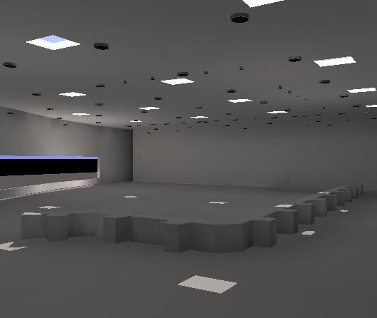
23 P a g e 23 Renderings and Images: The following image shows that the southern wall has a higher luminance than the other walls, which satisfies a design criterion.

24 P a g e 24 Power Allowance: Space Waiting Area Usage Luminaire Type # Luminaires Number of Ballasts ballast input watts Total Watts Ambient A Task A Wall- Wash B LED C Waiting Area Total Watts Sum: Space Square Feet: Actual W/SF: 1.27 Allowable W/SF: 1.3 Acceptable Additional Allowable Watts: 394
25 P a g e 25 Controls The space will be controlled by a Lutron system as shown. Three lighting panels will be located in the Electrical Closet, which is near the Conference Room on the second floor. The various control units will be located in the space in lockable column-mounted enclosures. This ensures that only authorized personnel can access the lighting controls. Two photo sensors connect to the Photocell Interface, which then allows Luminaires of Type A to dim accordingly. Occupancy sensors turn off the lights when the space has not been in use, and a timeclock device ensures energy is not wasted after events are over. For more system information, see the Controls section of this report. In addition to the Main Unit 1 controller, there are three smaller controls which can set the lighting to up to four different scenes.
26 P a g e 26 Examples of scenes are: Lighting Zone Luminaire Type(s) PRESET SCENE SCHEDULE Schedule For: Waiting Area / Ticket Queuing Load Type Day Cruise Night Cruise Conference Entertainment All Off 1 B CFL 0% 100% 100% 100% 0% 2 D CMH 0% 100% 0% 0% 0% 3 D CMH 0% 100% 0% 0% 0% 4 C LED 0% 100% (Note 1) 0% 100% (Note 2) 0% 5 A CFL Photo Sensor 50% Photo Sensor 50% 0% 6 A CFL Photo Sensor 50% Photo Sensor 50% 0% 7 A CFL Photo Sensor 50% Photo Sensor 50% 0% 8 A CFL Photo Sensor 50% Photo Sensor 50% 0% 9 A CFL Photo Sensor 50% Photo Sensor 50% 0% 10 A CFL Photo Sensor 50% Photo Sensor 50% 0% 11 A CFL Photo Sensor 50% Photo Sensor 50% 0% Skylight Shades 1 Photo Sensor Closed - Blackout Closed - Dimout Closed - Blackout Open 2 Photo Sensor Closed - Blackout Closed - Dimout Closed - Blackout Open 3 Photo Sensor Closed - Blackout Closed - Dimout Closed - Blackout Open 4 Photo Sensor Closed - Blackout Closed - Dimout Closed - Blackout Open 5 Photo Sensor Closed - Blackout Closed - Dimout Closed - Blackout Open 6 Photo Sensor Closed - Blackout Closed - Dimout Closed - Blackout Open 7 Photo Sensor Closed - Blackout Closed - Dimout Closed - Blackout Open 8 Photo Sensor Closed - Blackout Closed - Dimout Closed - Blackout Open 9 Photo Sensor Closed - Blackout Closed - Dimout Closed - Blackout Open 10 Photo Sensor Closed - Blackout Closed - Dimout Closed - Blackout Open 11 Photo Sensor Closed - Blackout Closed - Dimout Closed - Blackout Open 12 Photo Sensor Closed - Blackout Closed - Dimout Closed - Blackout Open Note 1 Note 2 Color-changing mode. Colors are set to blues, greens, purples Color-changing mode. Colors are set to all colors In addition, there are three occupant sensors and 2 daylight photo sensors which will allow the general ambient lights to dim when there is sufficient daylight contribution. Also, shading devices are linked to this control system so that the effective transmittance of the skylights is decreased. This allows the occupants (or facility manager) to have control over the daylight contribution.
27 P a g e 27 Controls: Zones Each circuit in the Waiting Area / Ticket Queuing is also its own zone. This allows for more precise daylight controlling.
28 P a g e 28 Daylighting in Waiting Area: Details The actual building design does not include skylights, but merely windows on the southwest and north walls. This daylighting study looks at the addition of 15 skylights in the Waiting Area / Ticket Queuing area. In addition to these skylights, the existing windows contribute to the total illuminance in the space. Both the windows and skylights are analyzed in this report. The only luminaire which will be linked to daylighting controls is Luminaire Type A, which provides general ambient light in the space. The model used in the daylighting study was created with regions in 3D Autocad. Each surface type was placed on a different layer type. Then, the model was imported into AGI32 for calculations. In AGI32, the correct building orientation was defined, and appropriate reflectance values were applied to each layer. These values align with the values estimated in Technical Report #1. The window transmittance was estimated to be 70%, and the skylight transmittance was 92%, according to the product selection from AIA Industries specifications. The ground reflectance was estimated to be 20%. The daylighting study consisted of 7 different dates (December 21 st through June 21 st ) on monthly intervals. A summary of the study is as follows: Site Name: Site Latitude: 36.91N Site Longitude: W Site Compass: 158 degrees (See Figure) Sky Conditions: Clear Electric Lighting: Off No Daylight Savings 21 st day of the month at 12:00pm Waiting Area / Ticket Queuing: Daylight Study Month Day Average Illuminance (fc) December January February March April May June Since the illuminance due to daylight exceeds the design criteria throughout the year, it is desirable to use shading devices controlled by photosensors. This is discussed more in the Controls section of the report. It is important to note that since this is a circulation space, its lighting can be dynamic. It is not problematic for direct sun penetration since guests are not expected to be reading for long periods of time, or participating in some other task where direct sunlight is undesirable. This space is much different than, say, the Conference Room, which must have more control of daylight due to the tasks the occupants perform. The illuminance calculations shown in the preceding table were calculated with AGI32. The same skylight layout was then applied in 3ds Max for rendering. The following sequence of images shows how the sunlight penetration changes from sunrise to sunset on March 21. It is interesting to note that as the day progresses, there is more daylight penetration.


29 P a g e 29


30 P a g e 30


31 P a g e 31 Details on the skylight used are as follows:
32 P a g e 32
33 P a g e 33 Additional information can be found in the Skylight Analysis section of the report. This includes mechanical and structural impacts as well as energy and cost saving analysis. Specific information regarding the skylight selection can be found in the Miscellaneous Equipment Appendix

.")


34 P a g e 34 Space 2: Lobby Spatial Overview The Lobby is the first major room that passengers enter from the Entry Pavilion Bridge. It is approximately 37-6 high and includes a 54-2 embedded mermaid image on the terrazzo-finished floor (Figure 1). There are several tiers of finished ceiling stepping up to the highest ceiling point (Figure 3). The windows on the western wall are full-height. Stemming from the Lobby are two Conference Rooms, two exits to an outdoor terrace, and four X-ray stations which lead to the Passageway. Finishes Materials in the Lobby contain cool, low saturated colors. The floor is semi-specular, but the other surfaces are mostly diffuse. The lower tier of ceiling has a warm wood finish. Materials Floor: Terrazzo Tile Reflectance 50% (Assumed) Walls: Skimcoat plaster over Gypsum Wall Board. Reflectance 70% (Assumed) Glass: Transmittance 20% (Assumed) Ceiling: Metal finish. Reflectance 10% (Assumed) Ceiling Wood: Reflectance 15% (Assumed)

35 P a g e 35 Plan and Section Drawings


36 P a g e 36 Luminaire Schedule Graphic Luminaire Type Description Luminaire Manufacturer Luminaire Catalog Number E One CFL lamp with a high power factor standard, with one injection molded socket. 13" Pendant-mounted, cylindrical luminaire with glare control. Housing is 0.064" rolled seamless aluminum with durable powder coat painted finish. Prescolite CF13P157EB - DM - Z F PAR20 lamp in a sturdy aluminum housed track light luminaire. It is adjustable and self-locking in all horizontal and vertical planes and features a hinged front with relamping handle for easy lamp changing. Lighting Services Inc LN20-5A-G G 1'x4' shallow direct-indirect recessed luminaire contains (2) T5HO lamps. Corelite R1-W-B-2-T5-1-D-UNV-14- T1 H Intelligent color-changing cove light. Each luminaire is 12" in length and has a narrow beam pattern of 20 degrees x 60 degrees. The luminaire uses a digital power-processing technology that integrates LED power and data management, which eliminates external power supplies. Color Kinetics icolor Cove MX Powercore
37 P a g e 37 Luminaire Schedule (continued) Luminaire Type Lamp Manufacturer Lamp Lamp Catalog Number Initial Lumens Design Lumens CCT CRI Volts Mounting E Philips (1) 70W CFL CFTR57W/ GX24q/ Pendant F Philips (1) 50W PAR20 50PAR20 / HAL / FL Track G Philips (2) T5HO F54T5 / 835 / HO / A / ALTO Downlight H N/A LED N/A N/A N/A 120 Cove. See Note 1 Luminaire Schedule (continued) Luminaire Type Ballast Manufacturer Number of Ballasts Ballast Catalog Number Input Watts Line Amps E Advance 1 IZT- 2T42- M3-BS F N/A 1 N/A G Advance 1 VEZ- 2S H N/A 1 N/A
38 P a g e 38 LLF Table Luminaire Type BF Cleaning Maintenance Category LLD LDD* RSDD Total LLF E 1 12 month IV F 1 12 month IV G 1 H 1 12 month 12 month IV VI *Assumes Clean Dirt Condition Mounting Notes 1. Cove-mounted. See the detailed diagram below. Design Criteria Illuminance: The Lobby is unique in the building because there is a significant amount of glass. Combined with lightly colored materials, there is potential for high Illuminance values on the workplane. Even though the IES does not recommend high levels of Illuminance, highly reflective materials along with large amounts of southern-facing glass mean that there will be far more Illuminance than required. Since the Lobby is the first space that people enter, it needs to be a transition space in the sense that the light levels need to help the eyes adjust to the interior environment of other spaces in the building. The light levels should be lower than the daylight on the outside. 5 fc on the work plane is recommended. Luminance: The luminance ratios from the Lobby to the Passageway should be low, even though the Passageway should be appear less bright. Glare: This means that the Glare should be considered because of the potential for direct sunlight. At night, glare from electrical lights should be minimized. VDT: There are two flat panel LCD video monitors mounted from the lower wooden ceiling at approximately 10 feet above the floor. It is important to consider Illuminance values on the screen so that the images are clearly visible. Accent Lighting: There is little need for accenting displays, except on the northwest wall.
39 P a g e 39 Color Appearance: Color rendering is important. Psychological Aspects: The space should feel spacious and welcoming. Wall emphasis could be used to make the space feel more spacious, but only at night since the contribution of daylight would render additional electric light practically useless. Appearance of Space and Luminaires: Sparkle could be used to enhance the feeling of the space. According to the IESNA Handbook, the appearance of the space and luminaires is very important. Since it is a large gathering space where occupants will not spend extended amounts of time reading, direct sunlight penetration is acceptable. It could enhance the space and make it feel large and welcoming. If there were a blind system (which there is not), it could be distracting from how the space should feel. The glass wall provides some shielding simply by its transmittance value. This makes the sky, clouds and water seem darker and bluer. Controls: It is important for the space to have controlled zones because not all electric lights need to be on all the time. There must be at least two control devices in this space since it is less than 10,000 SF (ASHRAE 90.1). Power Allowance: According to ASHRAE 90.1, 1.3 W/SF is the maximum allowable. Reflected Ceiling Plan See the lighting plan in the electrical section of this report. Details The details below show how the LED cove lighting is to be mounted.

40 P a g e 40 Performance data Note: The above values are presented in lux. Design Criteria Satisfied: The solution meets the design criteria for illuminance and luminance, as demonstrated in the preceding images. In addition to this criteria, the following shows how other design criteria are met: Illuminance: The illuminance values in the design exceed the recommended IES illuminance levels, but the design is acceptable because it is more of a multi-purpose space than the 5 fc recommendation intends. Luminance: There is higher luminance on the northwest wall because of accenting artwork. Also, the upper curved wall has a higher luminance from color-changing LEDs grazing its surface. Glare: During the day there is potential for glare caused by the sun. This is not problematic because the space is used as a circulation space during the day. VDT: The two wall-mounted televisions shall have a diffuse surface, so occupants can comfortably view the screen even during the day. Accent Lighting: The accent lighting on the northwest wall provides visual interest on a personal level. Color Appearance: All the lamps in this space have a high CRI. Psychological Aspects: The accent lighting on the upper circular wall contributes to a spacious environment by emphasizing the periphery. Appearance of space and luminaires: Since the overhead lighting exposes bare lamps, there is some sparkle potential. Controls: (see the following discussion) Power Allowance: (see the following discussion) Daylight: (see the following discussion)

41 P a g e 41 Renderings and Images:
42 P a g e 42 Power Allowance: Space Lobby Usage Luminaire Type # Luminaires Number of Ballasts ballast input watts Total Watts Ambient E Accent F Task G LED H Lobby Total Watts Sum: 3123 Space Square Feet: 5321 Actual W/SF: 0.59 Allowable W/SF: 1.3 Acceptable Additional Allowable Watts: 3794
43 P a g e 43 Controls The space will be controlled by a Lutron system as shown. For more system information, see the Controls section of this report. Examples of scenes are: PRESET SCENE SCHEDULE Schedule For: Lobby Lighting Zone Luminaire Type(s) Load Type Day Cruise Night Cruise Formal Entertainment All Off 1 E CFL 0% 100% 100% 100% 0% 2 E CFL Photo Sensor 100% 50% 50% 0% 3 H LED 0% 100% (Note 1) 100% (Note 2) 100% (Note 3) 0% 4 H LED 0% 100% (Note 1) 100% (Note 2) 100% (Note 3) 0% 5 F Halogen 0% 100% 100% 100% 0% 6 G Fluor 100% 100% 50% 50% 0% Note 1: Color-changing mode. Colors are set to blues, greens, purples Note 2: Slow color-changing mode. Colors are set to all colors. Note 3: Color-changing mode. Colors are set to all colors


44 P a g e 44 Space 3: Conference Room Spatial Overview This space is connected to Conference Room No. 1 (Room 201) when the folding partition is retracted. There is a continuous row of windows lining the curved exterior wall, and the ceiling height is There is a ceiling-mounted projector aimed to the ceiling-mounted retractable screen on the north wall (Figure 17). Finishes The materials in Conference Room #2 are low saturated and neutral colors. Dark, moveable wooden tables, desks and chairs are present throughout the space. The carpet is the same as in the Ticket Queuing and Waiting Lounge/Meeting Rooms. Materials Floor: 2 carpet tiles and is a light blue-gray color. Reflectance: 45% (Assumed) Walls: Light tan color. Reflectance: 47% (Assumed) Wood Tables: Reflectance: 15% (Assumed) Ceiling: Reflectance: 80% (Assumed)
45 P a g e 45 Plan and Section Drawings


 Luminaire Type Lamp Manufacturer Lamp Lamp Catalog Number Initial Lumens Design Lumens CCT CRI Volts Mounting J")
46 P a g e 46 Luminaire Schedule Graphic Luminaire Type Description Luminaire Manufacturer Luminaire Catalog Number J Designed for wall-washing, this luminaire is scaled for 8' to 12' walls. It features a smooth semi-gloss white exterior, door and lens, integral electronic ballast, screw in yoke for aim locking. CFL lamp. Elliptipar F114 - H124 - E02 - V K 2'x4' shallow direct-indirect recessed luminaire contains (2) T5HO lamps. Corelite R1 -W-B-2- T5-1-D-UNV- 24-T1 L 8" vertical triple tube open downlight, with CFL lamp. Features one-piece 22- guage galvanneal steel, high purity aluminum reflector. Prescolite LF8CFV32- EB-8CFV Luminaire Schedule (continued) Luminaire Type Lamp Manufacturer Lamp Lamp Catalog Number Initial Lumens Design Lumens CCT CRI Volts Mounting J Philips (1) 42W CFL CFTR42W/GX24q/ Ceiling. See Note 1 K Philips (2) T5HO F54T5 / 835 / HO / A / ALTO Downlight L Osram Sylvania (1) 42W CFL CF42DT / E / IN / 841/ECO Downlight
47 P a g e 47 Luminaire Schedule (continued) Luminaire Type Ballast Manufacturer Number of Ballasts Ballast Catalog Number Input Watts Line Amps J Advance 1 VEZ-1T42-M2-LD-K K Advance 1 VEZ-2S L Advance 1 VEZ-1T42-M2-LD-K LLF Table Cleaning Maintenance Category LLD LDD* RSDD Total LLF 12 month 12 month 12 month IV IV IV *Assumes Clean Dirt Condition Mounting Notes 2. Luminaire J is to be ceiling mounted so that all luminaires are at equal height A.F.F. Design Criteria Illuminance: The lighting system must accommodate various tasks that take place in a conference room. The IES Handbook recommends 30 fc on the workplane and 5 fc for vertical Illuminance. Luminance: There should be a blinds system which reduces luminance ratios from the outside objects compared to inside surfaces. This is particularly important during video presentations. Glare: It is important that there is minimal glare from daylight and luminaires. VDT: It is recommended that there be no more than 5 fc of vertical Illuminance on the projection screen. The conference is not equipped for video conferencing. Veiling reflections of highly luminous objects are problematic for laptop screens and should be avoided.
48 P a g e 48 Accent Lighting: Accent lighting should be used to highlight various displays on the walls. Color Appearance: The space should have a high CRI. The dark wood furniture will look best under a warm CCT. Psychological Aspects: Peripheral lighting emphasis is needed to help create an impression of pleasantness and assist with visual clarity. Appearance of Space and Luminaires: Conference Room #1 and #2 need to function coherently both alone and together. This applies for controls, lighting aesthetics and performance. Controls: To allow for several scenes, the luminaires must be dimmable and tied into a control system capable of programmable dimming. There must be at least two control devices in this space since it is less than 10,000 SF (ASHRAE 90.1). Power Allowance: According to ASHRAE 90.1, 1.3 W/SF is the maximum allowable. Reflected Ceiling Plan See the lighting plan in the electrical section of this report. Details The projection screen and mechanical partition exist in the original design. Performance data Note: The above values are presented in fc. The following vertical illuminance grids on the projection screen wall show the effects of changing the scene from a Night Conference to a Video Presentation.
49 P a g e 49 Night Conference Video Presentation Design Criteria Satisfied: The solution meets the design criteria for illuminance and luminance, as demonstrated in the preceding images. In addition to this criteria, the following shows how other design criteria are met: Illuminance: The illuminance criteria are satisfied with this design. As seen in a preceding image, the 30 fc criterion is satisfied. With the contribution of daylight through the windows, the lamps in select zones can dim and the work plane still maintains compliance with the design criterion. Luminance: During video presentations, the blackout window shades are programmed to be closed. Glare: During normal day conferences, the blackout are programmed to be open, but can be closed manually. The high ceiling height and careful aiming of wall-washing luminaires reduces glare in the space. VDT: Regarding vertical illuminance, technically the criterion value of 5 fc is not satisfied. However, 8 fc though not completely ideal, is sufficiently small enough to view video presentations clearly. Accent Lighting: The wall-washers accent the interior walls, some of which feature large artistic depictions of maps and other aquatic themes. Color Appearance: All the lamps in this space have a high CRI and 3500K CCT. Psychological Aspects: Peripheral lighting helps contribute to the feeling of pleasantness and assists with visual clarity. Appearance of space and luminaires: The control system is versatile. It allows the space to function as two independent rooms or one, large conference room. More information is presented in the controls section of this report. Controls: (see the following discussion) Power Allowance: (see the following discussion)

50 P a g e 50 Renderings and Images:
51 P a g e 51 Power Allowance: Space Conference Room Usage Luminaire Type # Luminaires Number of Ballasts ballast input watts Total Watts Wall- Wash J Downlight K Downlight L Controls Conference Room Total Watts Sum: 2867 Space Square Feet: 2542 Actual W/SF: 1.13 Allowable W/SF: 1.3 Acceptable The space will be controlled by a Lutron system as shown. For more system information, see the Controls section of this report. Examples of scenes are: PRESET SCENE SCHEDULE Schedule For: Conference Room Lighting Zone Luminaire Type(s) Load Type Day Conference Night Conference Video Presentation Entertainment All Off 1 J CFL 100% 100% 50% 100% 0% 2 J CFL 100% 100% 50% 100% 0% 3 J CFL 100% 100% 0% 100% 0% 4 K Fluor Photosensor 100% 50% 50% 0% 5 K Fluor Photosensor 100% 50% 50% 0% 6 L CFL Photosensor 100% 0% 50% 0% 7 L CFL Photosensor 100% 100% 50% 0% 8 L CFL Photosensor 100% 50% 50% 0% Window Shades 1 Open Open Closed - Blackout Open Open
52 P a g e 52 2 Open Open Room Partition Closed - Blackout Open Open 4 User User User User User Projection Screens 6 Up Up Down Up Up 7 Up Up Down Up Up Note: See the following explanation regarding how the Room Partition status affects the controls. The Conference Room can act as one large, continuous space, or, when the partition is used, it can be subdivided into two smaller conference rooms. For the sake of discussion, the northwest space is Conference Room 1 and the southeast space is Conference Room 2. There will be two Grafik Eye wall controls in the Conference Room (one in Conference Room 1 and one in Conference Room 2). A partition sensor will determine if the mechanical wall partition is open or closed. If it is open, then both Grafik Eye wall controls will control the whole space. On the other hand, if the partition is closed, each Grafik Eye wall control will only control the space in which it resides. Therefore, if the partition is closed, users cannot change the preset scenes or manual settings in the opposite conference room. Similarly, photosensors and occupancy sensors will only control the spaces in which each resides. This control setup is valuable because it saves energy by turning off unneeded light in the opposite space (if only one half is used). It also prevents users from inadvertently controlling lights, projection screens, and shades in another space. This system shall be installed according to Lutron s recommendations.
.")


53 P a g e 53 Space 4: Facade Spatial Overview The Entry Pavilion is the main entrance and exit point for most building users (Figure 24 and 28). During cruise ship boarding, people climb the stairs or take one of three elevators to the second floor and cross the bridge to the Lobby (Figure 25 and 26). People leaving a cruise exit the lower retractable bridge, which leads to the first floor of this 2-floor Entry Pavilion (Figure 27). The Entry Pavilion itself is a large, 2-floor outdoor space with a bridge. It is completely open to the outdoor environment. Extended lighting analysis will be focused on how the façade appears. The scope of analysis will not include the tasks of people using the Entry Pavilion because the scope of this analysis is the façade. Finishes The first floor façade is rugged concrete, which blends into the concrete pier. The second floor features a blue vertical-ribbed metal wall system. The Pedestrian Bridge is constructed with steel trusses and rests on concrete columns. The roof of the Pedestrian Bridge is ribbed metal and rests on steel columns. The overall feel is exposed structure and ruggedness, except for the finished brick floor near the elevators. Materials Floor: Red Brick Reflectance: 37% (Assumed) Façade: Blue, vertical-ribbed metal Reflectance 25% (Assumed) Façade: Concrete Reflectance 38% (Assumed)
 Plan and Section")
54 P a g e 54 Truss: Painted Aluminum Reflectance 48% (Assumed) Plan and Section Drawings


55 P a g e 55

 35W Ceramic MH CDM-T 35W/830 T6 ICT 3300 3300 3000 81")
56 P a g e 56 Luminaire Schedule Graphic Luminaire Type M Description Features rugged extruded aluminum cylinder with 3/16" end plates with rigid, extruded high purity aluminum with clear anodized specular finish reflector, superior asymmetric distribution. Luminaire Manufacturer Elliptipar Luminaire Catalog Number M X-06- A-000 Luminaire Schedule (continued) Luminaire Type Lamp Manufacturer Lamp Lamp Catalog Number Initial Lumens Design Lumens CCT CRI Volts Mounting M Philips (1) 35W Ceramic MH CDM-T 35W/830 T6 ICT Cantilever. See Mounting Note.
57 P a g e 57 Luminaire Schedule (continued) Luminaire Type Ballast Manufacturer Number of Ballasts Ballast Catalog Number Input Watts Line Amps Note M Advance 1 71A5005- P LLF Table Luminaire Type BF Cleaning Maintenance Category LLD LDD* RSDD Total LLF M 1 12 month IV *Assumes Very Dirty Dirt Condition Mounting Notes Luminaire Type M will be mounted so that it washes the desired surface. There are two mounting scenarios: mounting on concrete and mounting on the steel truss system. In both cases, Elliptipar s mounting accessories suffice. The luminaire will be mounted at the end of a cantilever beam that extends perpendicular to the surface. The luminaires are to be cantilever-supported according to the manufacturer s recommendations on the cut sheet. Design Criteria Illuminance: Illuminance levels are not critical for this façade lighting. There are Illuminance recommendations for the Bridge and Stairs, but this is not in the scope of the exterior analysis. Luminance and Accent Lighting: Visual clutter should be avoided. Only key architectural features should be illuminated. Color Appearance: CCT should be the same for each architectural feature.

58 P a g e 58 Psychological Aspects: The Cruise Terminal is located very near a major public park in Norfolk. There are many festivals and special events in this park each year. It is to the City s advantage to make this area spectacular. The building should be illuminated in a way that emphasizes the architectural and structural elements. Creating visual interest is critical. Appearance of Luminaires: The luminaires should appear industrial and durable. Large luminaires are acceptable because of the large building and ship scale. Controls: The lighting should have controls so that the Owner can turn the accent lighting only when desired. The safety lighting needs to be on according to code, and this light also allows security cameras to work properly. Lighting Plan See the lighting plan in the electrical section of this report. Performance data Design Criteria Satisfied: The solution meets the design criteria for illuminance and luminance, as demonstrated in the preceding images. In addition to this criteria, the following shows how other design criteria are met: Illuminance: Not critical for the scope of this project. Luminance and Accent Lighting: Visual clutter is avoided by accenting the horizontal architectural elements relatively uniformly. Color Appearance: All the lamps in this space have a high CRI and 3000K CCT. Psychological Aspects: The design emphasizes two horizontal elements: the concrete façade of the first floor, which acts as a visual foundation for the glass Lobby area, and the pedestrian bridge truss. Since the lobby

59 P a g e 59 curtain wall is made of glass, light escapes from the Lobby s surfaces into the environment. This adds visual interest, especially when the Lobby s color-changing LED cove lighting is activated. Appearance of space and luminaires: The luminaires do not themselves appear industrial. Instead, they functionally provide light which achieves the desired psychological effect. Controls: (see the following discussion) Power Allowance: (see the following discussion) Renderings and Images: The following illuminance grid shows that the horizontal uniformity of the concrete wall is relatively uniform, except for the very top of the wall. Despite this non-uniformity at the top of the wall, the design is still successful in achieving the desired psychological effect. Power Allowance: Space Façade Usage Luminaire Type # Luminaires Number of Ballasts Ballast input watts Total Watts Linear Feet W/ft Code Wall-Wash M Acceptable Wall-Wash M Acceptable Controls The space will be controlled by a Lutron system as shown. For more system information, see the Controls section of this report.
60 P a g e 60 Emergency Lighting The scope of this project does not include emergency lighting or controls. However, an interface can be used with the Lutron controls to make some lighting emergency powered. The current design does not have any lighting loads on a designated emergency panelboard, however. No emergency system panelboards or circuits are shown, as these are outside the scope. Controls The following control information is based on the GRAFIK Eye Designer 7.1 by Lutron. The solution consists of one system (New System 1) which controls all four spaces, a timeclock and system interface, and PC programmable main units. This solution provides panels and controls for both 120V and 277V loads, including the interface for the colorchanging LED systems. While the GRAFIK Eye Designer was set to Balance loads most effectively, it still recommends that 7 panelboards be installed. Even though this would not be the most efficient or cost effective design, for the sake of this thesis project, the GRAFIK Eye Designer 7.1 recommendations will be used. The existing panelboards are as follows: Existing Panelboards Panel Name Type Voltage Locations Served ELPL4 Dimming 120 Waiting Area, Lobby LPL3 Dimming 120 Lobby, Conference, Waiting Area, Waiting Area (LEDS) HPL3 Switching 277 Waiting Area, Conference EHPL4 Switching 277 Conference, Waiting Area, Façade ELPL2 Dimming 120 Façade EHPLP Switching 277 Façade EHPL2 Switching 277 Façade The Lutron GRAFIK Eye Designer solution recommends the following panelboards: Lutron GRAFIK Eye Designer Solution Panel Name Type Voltage Locations Served Panel Unit 1 Dimming 277 Waiting Area Panel Unit 2 Switching 120 Waiting Area Panel Unit 3 Dimming 120 Lobby Panel Unit 4 Dimming 277 Lobby Panel Unit 5 Switching 120 Lobby Panel Unit 6 Dimming 277 Conference Panel Unit 7 Switching 120 Façade The scenes for the façade lighting are linked to the system time clock, and can be overridden by the owner in case of special events.
61 P a g e 61
62 P a g e 62
63 P a g e 63
64 P a g e 64 Note: The line diagram above indicates more panels than actually will be used. For more information, see the Electrical section of this report. The following load summaries show the Lutron Zone number, which corresponds to the panelboard schedules in the Electrical section of the report.
65 P a g e 65
66 P a g e 66 Section 4: Electrical Introduction The four spaces in this report that have redesigned lighting solutions are: 1. Waiting Area / Ticket Queuing 2. Lobby 3. Conference Room 4. Façade The existing lighting panels that service these spaces are: 1. ELPL4 2. LPL3 3. HPL3 4. EHPL4 5. ELPL2 6. EHPLP 7. EHPL2 The following chart shows which panels serve each space ( X indicates service). Panel Waiting Area / Lobby Conference Facade Ticket Queuing Room ELPL4 X X X LPL3 X X X X HPL3 X X EHPL4 X X X X ELPL2 X EHPLP X EHPL2 X
67 P a g e 67 Design Technique For the purpose of this report, the design method is different than would occur in a real design. For this report, the design method is as follows: Locate all panelboards that have lighting loads in any of the four spaces listed above. Remove these existing lighting loads from these panelboards With some exceptions, leave these existing panelboards the same, minus the lighting loads that have been deleted. The theory is that these existing panelboards could be used for expansion. Add new panelboards according to the new lighting design. The rationalization behind this approach is that much of the new lighting is 277V, and a significant number of lighting panels in the existing design are at 208Y/120V. Also, some panels are designated dimming and switching in the existing design, but this does not necessarily coordinate with the new lighting design s needs (especially with the different voltage factor). Therefore, with some exceptions, existing panels will not be replaced. Instead, additional panel boards will be added to achieve the new lighting design. Also, the scope of this project does not include emergency power, but some general lighting circuits (particularly in the exterior spaces) are on emergency panelboards. The design technique for this project is to keep the original panelboards, and add new panelboards according to the Lutron GRAFIK Eye Designer software. Then, some consolidation will occur to reduce the total number of panelboards. Panelboard Information The existing panelboards from the original design are as follows. Note that the cells with a thick, black border indicate existing loads that the new design will replace.
68 P a g e 68
69 P a g e 69
70 P a g e 70
71 P a g e 71
72 P a g e 72
73 P a g e 73
74 P a g e 74 The existing panelboards are as follows: Existing Panelboards Panel Name Type Voltage Locations Served ELPL4 Dimming 120 Waiting Area, Lobby LPL3 Dimming 120 Lobby, Conference, Waiting Area, Waiting Area (LEDS) HPL3 Switching 277 Waiting Area, Conference EHPL4 Switching 277 Conference, Waiting Area, Façade ELPL2 Dimming 120 Façade EHPLP Switching 277 Façade EHPL2 Switching 277 Façade
75 P a g e 75 The Lutron GRAFIK Eye Designer solution recommends the following panelboards: Lutron GRAFIK Eye Designer Solution Panel Name Type Voltage Locations Served Panel Unit 1 Dimming 277 Waiting Area Panel Unit 2 Switching 120 Waiting Area Panel Unit 3 Dimming 120 Lobby Panel Unit 4 Dimming 277 Lobby Panel Unit 5 Switching 120 Lobby Panel Unit 6 Dimming 277 Conference Panel Unit 7 Switching 120 Façade For the purpose of this thesis project, and since emergency lighting and power systems are not in the scope of the redesign, the following is a list of recommendations: All existing panelboards will remain (none will be demolished) All existing panelboards which have loads in any of the four redesigned spaces will have modified loads Some, but not all, existing panelboards will carry new lighting loads from the redesign New panelboards will be required since the conditions of the existing design do not align perfectly with the proposed redesign. For example, if the new redesign requires a 277V Dimming panelboard and the existing design does not have an adequate panelboard which can handle this load type, then a new panelboard will be created For the sake of efficiency, the panelboard solutions that Lutron GRAFIK Eye Designer created will be consolidated when appropriate. The consolidated panelboard recommendation is as follows: Proposed Consolidation of loads ELPL4 EHPL4 ELPL2 EHPLP EHPL2 HPL3, Panel Unit 1, Panel Unit 4, Panel Unit 6 LPL3, Panel Unit 2, Panel Unit 5, Panel Unit 7, Panel Unit 3 From now on, the use of HPL3 in this report will include loads from the original HPL3, Panel Unit 1, Panel Unit 4 and Panel Unit 6. Also, LPL3 will include loads from the original LPL3, Panel Unit 2, Panel Unit 5, Panel Unit 7 and Panel Unit 3. The new, consolidated panelboards are as follows:
76 P a g e 76
77 P a g e 77 The emergency panelboards remain unchanged, except that the circuits outlined by a bold border (in the previous section) will be removed. Since emergency lighting is not in the scope of this project, the emergency panelboards were not resized. Technically, there is less load on the emergency panels, and therefore there is potential to reduce the panelboard size. All the lighting loads for this redesign are on either the LPL3 or HPL3. The actual sizes of these two panelboards will remain the same as the existing sizes. LPL3 has a 100 Amp bus and 100 Amp main circuit breaker. HLP3 has a 225 Amp bus and 225 Amp main circuit breaker. Both of these panelboards are redesigned to have additional 20% spare capacity. The feeder is designed to be the minimum size allowed by the National Electric Code NEC Table , based on the expected amps on the panel (total plus 20% expansion). LPL3 will have a (4)#12 THW feeder and HPL3 will have a (4)#10 THW feeder. These feeders, though technically correct according to the NEC, should be significantly larger according to engineering judgement. NEC Table
78 P a g e 78 Also, the shading devices run on low voltage (24 VAC), which Lutron recommends to be installed by the low-voltage contractors. The Controls section of this report indicates the load type. The panelboard locations will not change; all panelboards will remain in the existing electrical closets and electrical rooms, and LPL3 and HPL3 will be located in the second floor electrical closets. The location of controls is as follows: Controlled Location Control Units and Wall Stations Waiting Area / Ticket Queuing (2) column-mounted (1) wall-mounted Lobby (2) wall-mounted Conference Room (3) wall-mounted Facade (1) wall-mounted, located in Lobby Note: all control units and wall stations except those in the Conference Room are in locked enclosures.
79 P a g e 79 Space 1: Waiting Area / Ticket Queuing Introduction The Waiting Area / Ticket Queuing space is one architectural space, despite two separate room numbers. It is 12,063 square feet and is approximately 23-4 high, though the exposed steel trusses are curved, increasing the height in the spaces center. The northern curtain wall of windows is approximately 16 3 high. During a cruise event, the main purpose of this space is to form queues to the Mobile Ticket Counters and provide a waiting lounge area. During noncruise special events, the space is used as a ballroom and social gathering area. Luminaire Layout Note: There are no tick marks on this diagram, but since a Lutron control system is proposed, there will only be one neutral and one hot wire in every branch circuit, to every luminaire. Then, there will be a separate control wire from the Lutron system running to every luminaire. Fluorescent lamps dim according to the photosensor measurements, which respond to the illuminance from both electric light and light transmitted through the windows and skylights. The task lights provide illuminance for people at the ticket counters, and the LEDs contribute to a dynamic environment.
80 P a g e 80 HALF MOONE CRUISE & CELEBRATION CENTER LIGHTING PLAN: WAITING AREA SCALE: 1/16 = 1.0
81 P a g e 81 Lighting Zone Luminaire Type(s) PRESET SCENE SCHEDULE Schedule For: Waiting Area / Ticket Queuing Load Type Day Cruise Night Cruise Conference Entertainment All Off 1 B CFL 0% 100% 100% 100% 0% 2 D CMH 0% 100% 0% 0% 0% 3 D CMH 0% 100% 0% 0% 0% 4 C LED 0% 100% (Note 1) 0% 100% (Note 2) 0% 5 A CFL Photo Sensor 50% Photo Sensor 50% 0% 6 A CFL Photo Sensor 50% Photo Sensor 50% 0% 7 A CFL Photo Sensor 50% Photo Sensor 50% 0% 8 A CFL Photo Sensor 50% Photo Sensor 50% 0% 9 A CFL Photo Sensor 50% Photo Sensor 50% 0% 10 A CFL Photo Sensor 50% Photo Sensor 50% 0% 11 A CFL Photo Sensor 50% Photo Sensor 50% 0% Skylight Shades 1 Photo Sensor Closed - Blackout Closed - Dimout Closed - Blackout Open 2 Photo Sensor Closed - Blackout Closed - Dimout Closed - Blackout Open 3 Photo Sensor Closed - Blackout Closed - Dimout Closed - Blackout Open 4 Photo Sensor Closed - Blackout Closed - Dimout Closed - Blackout Open 5 Photo Sensor Closed - Blackout Closed - Dimout Closed - Blackout Open 6 Photo Sensor Closed - Blackout Closed - Dimout Closed - Blackout Open 7 Photo Sensor Closed - Blackout Closed - Dimout Closed - Blackout Open 8 Photo Sensor Closed - Blackout Closed - Dimout Closed - Blackout Open 9 Photo Sensor Closed - Blackout Closed - Dimout Closed - Blackout Open 10 Photo Closed - Closed - Closed - Open
82 P a g e Note 1 Note 2 Sensor Blackout Dimout Blackout Photo Closed - Closed - Closed - Sensor Blackout Dimout Blackout Photo Closed - Closed - Closed - Sensor Blackout Dimout Blackout Color-changing mode. Colors are set to blues, greens, purples Color-changing mode. Colors are set to all colors Open Open For information about loads on the panelboards, see the previous panelboard discussion and schedules. Space 2: Lobby Introduction The Lobby is the first major room that passengers enter from the Entry Pavilion Bridge. It is approximately 37-6 high and includes a 54-2 embedded mermaid image on the terrazzo-finished floor (Figure 1). There are several tiers of finished ceiling stepping up to the highest ceiling point (Figure 3). The windows on the western wall are full-height. Stemming from the Lobby are two Conference Rooms, two exits to an outdoor terrace, and four X-ray stations which lead to the Passageway. Luminaire Layout Note: There are no tick marks on this diagram, but since a Lutron control system is proposed, there will only be one neutral and one hot wire in every branch circuit, to every luminaire. Then, there will be a separate control wire from the Lutron system running to every luminaire. The pendants contribute to ambient light and the 1 x4 luminaires provide task and ambient light near the x-ray machines. Accent lighting illuminates art on the walls.
83 P a g e 83 HALF MOONE CRUISE & CELEBRATION CENTER LIGHTING PLAN: LOBBY SCALE: 1/16 = 1.0
84 P a g e 84 Lighting Zone Luminaire Type(s) Load Type PRESET SCENE SCHEDULE Day Cruise Schedule For: Lobby Night Cruise Formal Entertainment All Off 1 E CFL 0% 100% 100% 100% 0% 2 E CFL Photo Sensor 100% 50% 50% 0% 3 H LED 0% 100% (Note 1) 100% (Note 2) 100% (Note 3) 0% 4 H LED 0% 100% (Note 1) 100% (Note 2) 100% (Note 3) 0% 5 F Halogen 0% 100% 100% 100% 0% 6 G Fluor 100% 100% 50% 50% 0% Note 1: Color-changing mode. Colors are set to blues, greens, purples Note 2: Slow color-changing mode. Colors are set to all colors. Note 3: Color-changing mode. Colors are set to all colors Space 3: Conference Room Introduction This space is connected to Conference Room No. 1 (Room 201) when the folding partition is retracted. There is a continuous row of windows lining the curved exterior wall, and the ceiling height is There is a ceiling-mounted projector aimed to the ceiling-mounted retractable screen on the north wall. Luminaire Layout Note: There are no tick marks on this diagram, but since a Lutron control system is proposed, there will only be one neutral and one hot wire in every branch circuit, to every luminaire. Then, there will be a separate control wire from the Lutron system running to every luminaire. The partition sensors are located in this room, and determine which zones each wallstation controls. The controls are especially important in this space since it might be used for video presentations in either two separate rooms or one, continuous space.
85 P a g e 85 HALF MOONE CRUISE & CELEBRATION CENTER LIGHTING PLAN: CONFERENCE ROOM SCALE: 1/8 = 1.0
86 P a g e 86 PRESET SCENE SCHEDULE Schedule For: Conference Room Lighting Zone Luminaire Type(s) Load Type Day Conference Night Conference Video Presentation Entertainment All Off 1 J CFL 100% 100% 50% 100% 0% 2 J CFL 100% 100% 50% 100% 0% 3 J CFL 100% 100% 0% 100% 0% 4 K Fluor Photosensor 100% 50% 50% 0% 5 K Fluor Photosensor 100% 50% 50% 0% 6 L CFL Photosensor 100% 0% 50% 0% 7 L CFL Photosensor 100% 100% 50% 0% 8 L CFL Photosensor 100% 50% 50% 0% Window Shades 1 Open Open 2 Open Open Room Partition Closed - Blackout Open Open Closed - Blackout Open Open 4 User User User User User Projection Screens 6 Up Up Down Up Up 7 Up Up Down Up Up Note: See the following explanation regarding how the Room Partition status affects the controls. For information about loads on the panelboards, see the previous panelboard discussion and schedules.
87 P a g e 87 Space 4: Façade Introduction The Entry Pavilion is the main entrance and exit point for most building users (Figure 24 and 28). During cruise ship boarding, people climb the stairs or take one of three elevators to the second floor and cross the bridge to the Lobby (Figure 25 and 26). People leaving a cruise exit the lower retractable bridge, which leads to the first floor of this 2-floor Entry Pavilion (Figure 27). The Entry Pavilion itself is a large, 2-floor outdoor space with a bridge. It is completely open to the outdoor environment. Extended lighting analysis will be focused on how the façade appears. The scope of analysis will not include the tasks of people using the Entry Pavilion because the scope of this analysis is the façade. Luminaire Layout Note: There are no tick marks on this diagram, but since a Lutron control system is proposed, there will only be one neutral and one hot wire in every branch circuit, to every luminaire. Then, there will be a separate control wire from the Lutron system running to every luminaire. The façade lighting design only uses one fixture type and washes the concrete wall and the bridge truss. This, along with light from the Lobby creates an interesting, dynamic lighting design.
88 P a g e 88 HALF MOONE CRUISE & CELEBRATION CENTER LIGHTING PLAN: FACADE SCALE: 1/16 = 1.0
89 P a g e 89 HALF MOONE CRUISE & CELEBRATION CENTER LIGHTING PLAN: FACADE SCALE: 1/16 = 1.0
90 P a g e 90 Depth: Copper versus Aluminum Analysis The existing feeder material in the building is copper. Aluminum metal is less expensive, but can carry less current than a copper feeder of the same size. This means that larger wire sizes might be necessary, and possibly a different size conduit to hold the wires. The scope of this analysis is to determine the cost savings of switching to aluminum feeders in all panelboards and transformers. Material cost and labor cost of both wire and conduit is considered, and presented to show the total cost savings. The existing feeders are as follows:
91 P a g e 91
92 P a g e 92 The proposed aluminum system is as follows:
93 P a g e 93 The total cost of installing aluminum feeders is less than the total cost of installing copper feeders. There are other considerations to weigh before the decision is made to install aluminum feeders. For example, the expansion properties of the two metals are different. This impacts the connections and possibly the installation costs. The total cost savings of aluminum, however, is substantial and could be considered in feeder design, especially as material costs rise. Depth: Overall reduction in light le v e l s The existing design of the Half Moone Cruise & Celebration Center includes many luminaires that use energy inefficient lamps. The following evaluation shows the impact on the electrical distribution system if these luminaires are replaced with more energy efficient alternatives. The method of analysis is to compare the efficacies of each light source in a given space, and find the savings (in terms of watts) for that space if an alternative light source were used. This method assumes that each light source has the average efficacy in the range of efficacies given in IESNA Lighting Handbook Figure Data taken from IESNA Lighting Handbook Figure 26-3: Light Source Efficacy Standard Incandescent 13 Tungsten halogen 18 CFL (5-26W) 40 CFL (27-40W) 65 Fluorescent 82 Metal Halide 72 HPS 80 Given this data, and assuming that the total lumen output in the space will remain the same (as in, the zonal lumen method), here are the results of this approximate method. Three spaces will be evaluated in this study: the Waiting Area / Ticket Queuing Area, the Conference Room, and the Luggage Area on the first floor. Both the Waiting Area / Ticket Queuing Area and the Conference Room have already been redesigned. The loads in both of these areas have been reduced, and the feeders and panelboards have been designed around these loads. Note that the panelboards themselves do not change in size because the loads have been consolidated from multiple spaces. This gives the illusion that there is no energy savings, but the loads on the existing emergency panelboards have been reduced. Since the emergency system is not in the scope of the project, these emergency panelboards have not been reduced in size, and therefore the switchgear will not change due to the reduced load. The major space that will change is the 28,300 SF Luggage Area on the first floor (Room 137). The existing design uses metal halide lamps, but the new design will use the more efficient fluorescent lamps. The ratio of efficacies for metal halide and fluorescent is 72/82 = 0.878, meaning that the new design will use only 87.8% of the energy that the existing design uses. Since both systems are at the same voltage, this corresponds to approximately 87.8% of the current (amps). The existing load in this space is divided between EHPL1 and EHPL2. Here are the existing panelboard schedules, and the loads to be replaced are highlighted.
94 P a g e 94
95 P a g e 95 Below are the updated values, which are 87.8% of the original values.
96 P a g e 96
97 P a g e 97 There is very little reduction in the current requirements used to size the panelboard. This is largely due to the fact that the existing metal halide lights are very energy efficient to begin with. If, for example, incandescent light sources were replaced with fluorescent, there would be a large reduction in the current requirements for two reasons. The first would be due to the luminous efficacy. The second reason would be due to the voltage differences. The incandescent lamps would require more current because this equipment runs at 120V. The fluorescent can be run at 277V, which means that the current requirements are reduced. This is a similar situation to what occurred in the Waiting Area / Ticket Queuing Area. Since the redesign of the lighting system did not include much 120V lighting, the overall current requirements were less (and thus there is less current on the panelboard).
98 P a g e 98 Protective Device Coordination Study A sample fault current calculation was performed for the following system path: Unit Substation Transformer Switchboard SWBD 1 Distribution Panel HP1 Panelboard LP1 Fault Current Analysis (Per Unit Method) System Voltage = 480 Base KVA = 10,000 Utility Co. Avail. Fault = 100,000,000 Utility Primary X(p.u.) = KVAbase / Utility S.C. KVA = R(p.u.) = Transformer Secondary %Z = X(p.u.) = %X * KVAbase / (100 * KVAxfrmr) = X/R = 11 R(p.u.) = %R * KVAbase / (100 * KVAxfrmr) = %X = 4.76 %R = 0.43 kva = 2500 Switchboard Wire = 3/0 X = (L/1000) * XL * (1/Sets), X(p.u.) = Length = 20 R = (L/1000) * R * (1/Sets), R(p.u.) = Sets = 2 X = R = Panelboard 1 Wire = #2 X = (L/1000) * XL * (1/Sets), X(p.u.) = Length = 45 R = (L/1000) * R * (1/Sets), R(p.u.) = Sets = 1 X = R = 0.21 Panelboard 2 Wire = 350 X = (L/1000) * XL * (1/Sets), X(p.u.) = Length = 15 R = (L/1000) * R * (1/Sets), R(p.u.) = Sets = 1 X = R = ΣX ΣR ΣZ I sc (A) ,281, , , , ,307
99 P a g e 99 The following table summarizes the available fault in the previous table, and shows the standard breaking rating (in amps): Point A Summary Results of Fault Analysis Location Available Fault Standard Breaker Rating (A) Unit Substation Transformer 62,975 64,000 B Switchboard SWBD 1 54,491 64,000 C Distribution Panel HP1 21,037 22,000 D Panelboard LP1 19,307 22,000 The following graphs shows the circuit breaker time/current curves for 3 circuit breakers used in the building: 20A circuit breaker for a load on LP2, 225A circuit breaker (main circuit breaker for LP2), and 400A circuit breaker (main circuit breaker for HP2). Unit Substation Transformer Switchboard SWBD 1 Distribution Panel HP2 Panelboard LP2 These 3 circuit breakers are coordinated well because if there is a short circuit, then the circuit breaker farthest from the switchgear will trip first. It is desired to have the smallest circuit breaker trip first (the circuit breaker closest to the short circuit or overload), so that the circuit breaker closest to the problem will trip instead of a larger, unnecessary portion of the building to lose power. The coordination of these circuit breakers is shown on the following graph.

100 P a g e 100
101 P a g e 101 Section 5: Skylight Analysis (Breadths) Introduction At 16,600 square feet, the Waiting Area / Ticket Queuing area is a large percentage of the second floor area. Part of the lighting design for this space includes adding skylights and dimming the fluorescent luminaires according to the photosensor controls. Beyond simply a lighting design decision, the skylights impact other building systems such as the mechanical cooling load and the roof structural system. It is important to evaluate the impact on these other systems, and the results are described in the following two sections of this report. Mechanical Impact There is no doubt that subtracting roof area and adding skylight glass will affect the cooling load of the building. The purpose of this mechanical study is to determine what the impact will be. The only change on the space will be subtracting roof area and adding skylight area. Therefore, for the purpose of this study, constant sources which contribute to the cooling load do not need to be considered. For example, people, appliances, and exterior walls will not affect the study. Hand calculations are included at the end of this section. The roof area of the Waiting Area / Ticket Queuing space is 16,600 square feet, or 1,542 square meters. This study compares the cooling load of the existing roof with the cooling load of the proposed skylights. Assumptions: R-value of the roof = 4 m 2 K/W U-value of roof = 0.25 W/(m 2 K) No adjustments to the CLTD (Cooling Load Temperature Differences) for either of the two scenarios Zone B for SCL (Solar Cooling Load) calculations The method and equations used are from 1997 ASHRAE Fundamentals Handbook 1.0 = F sa, which is the lighting special allowance factor Lighting analysis is for special events in the building, where light is needed for 12 hours. Assume 10:00 to 22:00 building use during special events. In the skylight scenario, no electric lighting is needed during the hours 13:00 through 17:00. Existing roof (no skylights): Area (A) = 1,542 m 2 U=0.25 Equation: q=u*a*(cltd), where q is in Watts According to Table 31, the Roof Value = 4, and the CLTD values are as follows. Applying the equation q=u*a*(cltd), the following cooling load (in Watts) is found:
102 P a g e 102 CLTD Values Hour: CLTD: Watts: Note: this study only looks at the peak values in the day, hours 13 through 17. In addition to the load described in the previous table, the electric lighting contributes to the cooling load as follows: q el =W*F ul *F sa *(CLF el ) o q el (Watts) o W = total watts in the space (51 luminaires with (4) 42W lamps each) o F ul = lighting use factor, used to indicate approximate dimming o F sa = lighting special allowance factor (assumed to be 1.0) o CLF el = lighting cooling load factor. The CLF is determined for each hour by determining the Zone (Table 35A ASHRAE) and how long the lights were on at the desired time (Table 38 ASHRAE). Number of hours that lights are ON: Lighting Impact Hour: CLF el : q el (Watts): Existing Roof (No Skylights) Hour: Total Watts: Roof with skylights: This calculation is a two-step process. First, the effective area of the roof material is considered. Then, the skylight is considered in two equations (one for conduction and one for solar radiation). Then, the cooling loads are summed to show the total cooling load for the roof with skylights scenario. Note that it is assumed there is no electrical light contribution in this scenario. Roof material calculation: Area (A) = 1,542m 2 (15 skylights x m 2 per skylight) = 1,499 m 2 of roof material U=0.25 Equation: q=u*a*(cltd), where q is in Watts Existing Roof (reduced area) CLTD Watts: Skylight glazing material calculation:
103 P a g e 103 Conduction calculation: o U=1.3 (from manufacturer) o A=43.16 m 2 (15 skylights x m 2 per skylight) o Equation: q(cond) = U*A*(CLTD) Skylight Glazing (Watts due to Conduction) CLTD Watts: Solar radiation calculation: o A=43.16 m 2 (15 skylights x m 2 per skylight) o SC = Shading Coefficient (from manufacturer) = 0.39 o SCL = Solar Cooling Load from Table 36, (W/m 2 ) Skylight Glazing (Watts due to Solar Radiation) SCL Watts: Lighting Impact q el (Watts): Therefore, the total cooling load in this scenario is the sum of the existing roof (reduced area), skylight glazing (watts due to conduction), and skylight glazing (watts due to solar radiation). The total cooling load in this scenario is as follows: Total Cooling Load Hour: Watts: Conclusion: There is a significant difference in the cooling load when the skylights are added. This is mostly due to the solar radiation that is transmitted through the glazing. The difference is minimized when electrical lights are considered. In the first scenario, there are no skylights but there is cooling load due to electrical lights. In the second scenario, there is no electrical light contribution, but there is more cooling load from the reduction of the roof load (at a higher R value), the addition of the glazing (at a lower R value), and the addition of the solar radiation component. The solar radiation component drives the sum of these components up so that the result of adding skylights is a larger cooling load. However, this analysis does not consider coefficients of performance and how the total energy analysis. If the 51 luminaires are turned on at 100% (as in scenario 1), then 9,486 watts would be used in energy consumption. From the mechanical view, this is heating the space. In scenario 2 (where there are skylights), there is a 9,486 watt electrical power savings over select hours in scenario 1. Therefore, skylights should be added to this space.
104 P a g e 104 Cooling Load Comparison (Watts) Hour: Existing Roof (no skylights): Proposed Roof (with skylights): Difference:

105 P a g e 105 Mechanical Appendix:

106 P a g e 106
107 P a g e 107 Mechanical and Daylight Analysis: The following analysis is based on SkyCalc, an Excel-based computer program that calculates the impact of adding skylights. It predicts the energy and cost impact of the skylight system throughout the year. According to the operational manager of the building, the building lights in this space are on according to the following schedule: Monday through Friday: 3 hrs per day Saturday and Sunday: 0 hrs per day (except for maintenance or special events) Special events: 2 per week, at 12 hours per event This estimated information was inputted into SkyCalc as a user-input option. The cost of electricity and gas is estimated from information provided by Dominion Power and Virginia Natural Gas. The results are as follows. The two most important graphs are at the end of this section: Total Annual Energy Savings from Skylights and Total Energy Cost Savings from Skylights. According to SkyCalc, adding these particular skylights will save 9,980 kwh/year and $535/year. While the cost savings might be minimal, this is linked to the cost of utilities in Norfolk, which could change over the course of the building s life. It is important to note that there is a large energy savings from the reduction of electrical light usage. Therefore, even though there might be a long payback period, it still is beneficial to add skylights in this space.
108 P a g e 108
109 P a g e 109
110 P a g e 110
111 P a g e 111
112 P a g e 112
113 P a g e 113 Structural Impact Background Information: Beyond the mechanical impact of adding skylights, the building structure is affected, too. The following analysis seeks to determine if adding these skylights is possible with the existing structure, or if additional supports are necessary. The roof deck used on the building is Epic Wideck WHF gage. It spans between the supertrusses as shown on the diagram below.
114 P a g e 114
115 P a g e 115
116 P a g e 116 Analysis To perform structural analysis, RAM Structural System was used. The scope of the analysis was limited to the area between two supertrusses. The following process shows the major steps in creating the structural model: Create elements and designate material properties o Grid lines o 4 Columns o Slab o Beams o Slab openings Run analysis Interpret analysis


117 P a g e 117 Test 1: With Skylight Openings Test 2: Without Skylight Openings Unfortunately, after extensive modeling and problem checking, RAM still produced 12 errors and was unable to analyze the building. These errors were the result of not having beams on the perimeter of the slab openings. However, it would have been an inappropriate model to add beams in the model, since no beams are present in the actual design. To resolve this problem, separate slabs were created act as a single slab. These individual slabs were modeled to outline the skylight openings so that no Slab Opening function is needed. The resulting solution is that both cases pass the test. The steel member module check indicated that the members were adequate for load. In the image below, the green and blue colors visually indicate that the structure passes. Two trials were run: one with slab openings (which corresponds to the modified structure with skylight openings)and one with no slab cutouts (which corresponds to the existing structure). Both cases pass. Therefore, this method of analysis indicates that the structure is adequate to handle the additional line loads of the skylights.


118 P a g e 118
1.4 Rollins Center Performance Hall
 1.4 Rollins Center Performance Hall The Rollins Center is the name of the multi-purpose performance hall housed inside of Dover Downs. The performance hall is one of the highlights of Dover Downs. It is
INDEPENDENCE VISITOR CENTER PHILADELPHIA, PA
 The theater is located off the main hall of the Independence Visitor Center as seen in Figure 5.1. This theater is primarily used for watching movies having to do with the history of Philadelphia and Pennsylvania.
Space #2: Science Room 1
 Space #2: Science Room 1 size: approx. 32 x26 x 9 853 s.f. description: The Science Room is the smallest space being redesigned, and also the most simple. The room is basically shaped like a large rectangle,
Northwest façade of building
 Northwest façade of building North West Lighting The exterior space to be re-designed is composed of the north and west facades of the library. For this area, the building, using the symbol of the sun,
Classroom (505) Lighting Redesign
 Lighting Redesign") Classroom (505) Lighting Redesign Description of Space The 60-person classroom is located on the fifth floor of the building. The fifth floor of the Dorrance H. Hamilton Building also includes other classrooms,
Classroom (505) Lighting Redesign Description of Space The 60-person classroom is located on the fifth floor of the building. The fifth floor of the Dorrance H. Hamilton Building also includes other classrooms,
Lighting Depth: Physical Therapy Suite Franklin Care Center, Franklin Lakes, NJ
 Physical Therapy Suite Overview: The physical therapy suite will be used by the patients for physical rehabilitation. It is similar to a small gym with exercise mats, bikes, a treadmill, stairs, parallel
Second Floor Circulation
 Second Floor Circulation Introduction As you enter Redifer commons the first space you come to is the vestibule. From the vestibule you can proceed into Louie s or through a set of doors into the Lobby.
1.3 Auditorium Lighting Redesign
 1.3 Auditorium Lighting Redesign 1.3.1 Appearance Description Unlike most of the spaces in Proctor High School, the auditorium is one of the few that did not undergo a previous lighting renovation. Ironically,
spacing, efficiency, uniformity, and aesthetic appearance of light patterns for final design for the construction document phase.
 spacing, efficiency, uniformity, and aesthetic appearance of light patterns for final design for the construction document phase. Multipurpose Room Overall Design Concept When visiting the Library, Ronald
The Bahen Centre for Information Technology. Lecture Hall Lighting Redesign. Introduction. University of Toronto ~ Toronto, Ontario, Canada
 Lecture Hall Lighting Redesign downlight system, and the other will be an indirect pendant mounted lighting system. Figure 5.1 ~ Ground floor plan; Lecture hall location with respect to the entire building
Microfilm and Reading Area
 Lighting Depth Depth Analysis: Lighting Design Lighting design is not just the placement of lights, but the concept and feeling it portrays as well. ASHRAE 90.1 and LEED both have to be observed, while
Executive Summary. Technical Assignment #1 - Existing Conditions Report Relevant computer files: P:\Singley_Tech1_files
 Eric Singley Lighting / Electrical Richard G. Mistrick, Ph.D., P.E., FIES Natty Boh Building Baltimore, Maryland Technical Assignment #1 - Existing Conditions Report Relevant computer files: P:\Singley_Tech1_files
Existing Lighting Conditions
 Casey Schardt Lighting/Electrical Option Howard County General Hospital, Columbia, MD Primary Faculty Consultant: Dr. Mistrick Technical Assignment #1. October 9, 2003 Existing Lighting Conditions The
Lighting Existing Conditions and Design Criteria Report
 Lighting Existing Conditions and Design Criteria Report Executive Summary: This Lighting Existing Conditions and Design Criteria Report will examine and describe the existing lighting systems and all existing
Josh Lutton. Lighting/Electrical DEF Workforce Development & Technology Building Dubois, PA. 4-1 Exterior. Briefing
 4-1 Exterior Briefing The exterior space that I will be trying to light will be the exterior entrance paths/courtyard. Basically the space is behind the building, away from public view. You access it by
Kimberly Morton Lighting/Electrical COSI - Columbus, Ohio
 Kimberly Morton Lighting/Electrical COSI - Columbus, Ohio Faculty Consultant: Dr. Moeck Existing Lighting Conditions and Design Criteria Picture Courtesy of JA55 Executive Summary: This report includes
Ronald Reagan Presidential Library. Reagan Country Café
 Reagan Country Café Design Concept Although the interior characteristics of this space take on a different theme than the others, it is important to continue a smooth transition from the café to the Multipurpose
REVISIONS Summary of Change. 6/1/12 All Replaced entire document with new revision
 Revision Date Section REVISIONS Summary of Change 6/1/12 All Replaced entire document with new revision REV 6/12 1 of 5 UNIVERSITY CONTACT: INTERIOR LIGHTING Electrical Services, Maintenance & Operations
Computer Lab. Furniture: Floor Plan and Lighting Plan:
 Executive Summary This report is an analysis of the existing lighting conditions for the Computer Labs, Pechter Family Music Room, Lecture Hall/Video Conferencing Room, and Main Corridor of the Hawthorn
Lighting Existing Conditions and Design Criteria Report
 Lighting Existing Conditions and Design Criteria Report Executive Summary: I decided to focus my efforts on the fourth floor of the building which I believe will be the most challenging when considering
VEER takes a detour from the ordinary, infusing texture and form into a sleek new direct/ indirect luminaire.
 VEER takes a detour from the ordinary, infusing texture and form into a sleek new direct/ indirect luminaire. Smooth planes on the rectilinear exterior turn the corner to subtle sweeping curves on Veer
Table 32 - Typical Guest Room Length 18 ft Width 13 ft Area 234 sq ft Total No of 279 rooms Guest Rooms
 Lighting Analysis The current lighting system in the encompasses a variety of spaces and uses many different types of light fixtures and lamps. The main reason for studying the lighting systems of the
Technical Assignment #1 Lighting Existing Conditions and Design Criteria Report
 Technical Assignment #1 Lighting Existing Conditions and Design Criteria Report William H. Gates Hall Seattle, WA Katherine Jenkins Lighting/Electrical Option October 5, 2006 Faculty Advisor: Dr. Mistrick
Use timers, motion detectors, remote controls, and photocells to reduce waste.
 Exterior Exterior luminaires include large-area flood and small-area, landscape, and accent luminaires. They illuminate building facades, pathways, and landscapes and can provide lighting for safety, security,
An Introduction to Interior Lighting Design
 An Introduction to Interior Lighting Design G u y e r P a r t n e r s 4 4 2 4 0 C l u b h o u s e D r i v e E l M a c e r o, C A 9 5 6 1 8 ( 5 3 0 ) 7 7 5 8-6 6 3 7 j p g u y e r @ p a c b e l l. n e t
Lighting Depth Study
 Lighting Depth Study Board room The board room is located on the second floor of the Hall Corporate Headquarters with room number 223. The dimensions of the space are approximately 40Ft. x 20.5Ft. giving
1.1 Façade and Building Entrance
 1.1 Façade and Building Entrance 1.1.1 Introduction Figure 1.1 Exterior Entrance View The main entrance to the building is located between the two wings of the building. The juxtaposition of the cylindrical
Lighting Depth. Page 14
 Lighting Depth Introduction The over-arching theme to the lighting design for Art & Visual Technology building was to design a unique and creative solution to foster imagination and ingenuity among faculty
EXTERIOR LIGHTING DESIGN
 October 31, 1995 (Revised: February 21, 2002 June 11, 2009) Technical Bulletin 95-001 Development of Regional Impact Guidance for EXTERIOR LIGHTING DESIGN INTRODUCTION The intent of this Technical Bulletin
DOUGLAS COUNTY ZONING RESOLUTION Section 30 Lighting Standards 3/10/99. -Section Contents-
 SECTION 30 LIGHTING STANDARDS -Section Contents- 3001 Intent... 30-2 3002 Applicability... 30-2 3003 Exceptions... 30-2 3004 Prohibited Lighting... 30-2 3005 General Requirements... 30-3 3006 Sign Lighting...
4. Special Systems Design: including Fire Alarm and Security. C. Electrical and Telecommunications Ductbanks: Refer to Section 16118
 PART 1: GENERAL This section of the design standard outlines general requirements for electrical and telecommunications designs to be performed for the University of Texas at Austin. This standard is intended
Light In Architecture
 Designing with Light Light plays a central role in the design of a visual environment. The architecture, people and objects are all made visible by the lighting. Light influences our well-being, the aesthetic
VT & VTTB SERIES. Comfortably illuminates the participants while rendering an excellent video image.
 VT & VTTB SERIES Fixtures for Drywall and T-Bar th Now wi ns! tio LED op Project Econolite Control Products, Inc. Anaheim, California Specifier Leelite Design Tustin, California Photographer Dell Aquila
A R E A & S I T E WA L L M O U N T E D F LO O D B O L L A R D S
 A R E A & S I T E WA L L M O U N T E D F LO O D B O L L A R D S A COMPLETE LIGHTING SOLUTION Distinctive designs with signature accents and uncompromising performance Lithonia Lighting is known as the
Rendering and Documenting Light
 Rendering Light Light and Air 1 Light and Air 4 2 Compositions of Light the development of a concept What Is The Desired Look? Light Mapping Direction of Light Painting with Light Light Mapping use a number
Lighting for seniors
 Lighting for seniors Senior Vision Smaller pupils (reduced light entering the eye) Loss of ocular transparency (scattering) Yellowing of the ocular media Loss of accommodation Photobiological Effects Neuroendrocrine
For energy savings select ceiling-mounted luminaires that use fluorescent lamps.
 Cei li ng-mounted Ceiling-mounted luminaires include diffusers and track and adjustable heads that attach directly to the ceiling. They are easy to install compared to recessed luminaires because they
ELECTRICAL GENERAL DESIGN AND CONSTRUCTION STANDARD PART 1: GENERAL Electrical/Telecommunications Design
 PART 1: GENERAL 1.01 Electrical/Telecommunications Design A. This section of the design and construction standard outlines general requirements for electrical and telecommunications designs to be performed
Basic Lighting Terms Glossary (Terms included in the basic lighting course are italicized and underlined)
") Basic Lighting Terms Glossary (Terms included in the basic lighting course are italicized and underlined) Accent Lighting Directional lighting to emphasize a particular object or draw attention to a display
Basic Lighting Terms Glossary (Terms included in the basic lighting course are italicized and underlined) Accent Lighting Directional lighting to emphasize a particular object or draw attention to a display
2. Electrical rooms shall be centrally located and stacked so that feeder conduits and bus duct are run as straight and short as possible.
 PART 1: GENERAL 1.01 Electrical/Telecommunications Design A. This section of the design and construction standard outlines general requirements for electrical and telecommunications designs to be performed
Energy Efficient Lighting
 Energy Efficient Lighting Watt You Need To Know Tuesday, October 8th, 2013 1:00 PM Presented By: Bryan Heitzmann, Training & Edu. Dev. Specialist Pennsylvania Housing Research Center www.engr.psu.edu/phrc
03/7/12 Issuance UTD Section Page 1 of 5 Electrical General
 SECTION 26 01 00 ELECTRICAL GENERAL PART 1: GENERAL 1.1 Electrical/Telecommunications Design 1.1.1 This section of the design and construction standard outlines general requirements for electrical and
Interior Accent. Lighting. Kaleidoshade 2
 Interior Accent Lighting The presents new opportunities for illuminating retail or commercial building interiors having large open wall space. Because of its linear fluorescent design, lighting is more
TOKISTAR LIGHTING....The Art of Lighting Innovation SELECTION GUIDE
 TOKISTAR LIGHTING...The Art of Lighting Innovation SELECTION GUIDE Content ADVANTAGE - 3 Cove lighting offering both LED modules and xenon lamps GRADIENT - 4 High-output LED system for use in wall grazing
Gravity. High Power 4, 6 & 8-Inch Downlighting
 Gravity High Power 4, 6 & 8-Inch Downlighting Unlimited Capabilities Powerful Performance From beautiful architectural cylinders to precisely tuned wall washers, performance based design is balanced with
 PureFX is a revolutionary lighting system that utilizes Ledalite s MesoOptics technology to purify and control light. It offers the perfect blend of brightness, control and energy efficiency making happier
NOT SO SCARY LIGHTING MATH
 NOT SO SCARY LIGHTING MATH Measuring Light / Light Metrics Energy Watts and Codes Illumination Light Levels Brightness 1 Lighting Needs Power: Electrical Systems 1 Lighting Needs Power: Wires Distribute
Final Thesis Report. jack risser lighting/electrical. s. good the nerman museum. overland park, kansas feb 16 th, 2014
 Final Thesis Report jack risser lighting/electrical s. good the nerman museum overland park, kansas feb 16 th, 2014 2 Executive Summary: 3 Table of Contents: Executive Summary 2 Background 4 Building Statistics
Redifer Commons Outline
 Large Dining Area Louie s Convenience Store Second Floor Circulation Exterior Front Façade Outline Electrical Depth Structural Breadth Construction Management Breadth Summary Acknowledgements Questions
PENDANT MOUNT - DIRECT
 Project Type Louver Notes Flush Spotless Lens - down Glo Lens - up Glo Lens up and down PERFORMANCE PER LINEAR FOOT AT 3500K NOMINAL LUMEN OUTPUT INPUT WATTS* EFFICACY SHIELDING 1000 lm/ft 9.9 W/ft 97
HOME SCIENCE CHAPTER 3: LIGHTING IN THE HOME Class: X
 HOME SCIENCE CHAPTER 3: LIGHTING IN THE HOME Class: X 2017-18 Answer the following questions. 1 What is a foot candle? Ans Light is usually measured in terms of Foot candles. A Foot Candle is the degree
HBL Series High Bay LED
 HBL Series High Bay LED At Big Ass Solutions, we've put our right and left brains together to produce lighting fixtures that leave the competition in the shadows. Our Big Ass Light LEDs are conceived and
Calculite White LED 4 " Adjustable Accent. Professional-grade downlighting
 Calculite White LED 4 " Adjustable Accent Professional-grade downlighting Calculite White LED 4 " Adjustable Accent Professional-grade downlighting Calculite White LED Precision. Performance. The Philips
Small Form Factor. Track & Recessed Multiples
 MX Downlighting, Small Form Factor Pendants, Track & Recessed Multiples Small Aperture Dynamic Solution The MX Family of LED downlighting, pendants, track & recessed multiples is built on an award-winning
RAIL / GRANDE RM2 & RM4 Series. by Metalumen
 RAIL / GRANDE RM2 & RM4 Series 15 by Metalumen 15 RAIL / GRANDE RM2 & RM4 Series We believe that well-designed spaces are created by inspired designers working with inspiring products. We also believe
Community Design Standards
 In accordance with the Zoning Ordinance Update Adopted December 15, 2015 OUTDOOR LIGHTING Sections: 3.1 Purpose and Intent 3.2 Definitions 3.3 Lighting Plans Required 3.4 Outdoor Lighting Limits 3.5 3.1
QuickShip. Shipping in 48 hours
 Shipping in 48 hours January 2017 The Williams QuickShip program offers a competitive suite of topselling products to support immediate lighting requirements on any job. Shipping within 48 hours, our centrally
Ceramic Metal Halide Lighting
 Since 1895 Bulletin 13CMH2 Innovating Design and Performance Ceramic Metal Halide Lighting JW Marriott Grand Rapids, MI. Luminaires by Kirlin. Gary Steffy Lighting Design, Adjustables, Wall Washes Recessed
Video Conference Indirect Wash Fluorescent Fixture
 Indirect Wash Fluorescent Fixture 369498e 1 04.05.17 Lutron s provide a combination of horizontal and asymmetrical vertical illumination for optimal video conference lighting. The unique reflector design
A family of architectural luminaries for the security and comfort of people in outdoor spaces. Classics Series
 A family of architectural luminaries for the security and comfort of people in outdoor spaces Classics Series Keene MAKES LIGHT WORK Families offer us variety of character, and diversity within a common
Panache. Recessed, Surface & Suspended
 Panache, Surface & Suspended Polymetrics make all the difference Panache uses a three layer refractive system and back plate, which provides an extremely uniform light distribution across the whole diffuser.
Project Details: average average footcandles,
 LINERO Project Details: Linero 6 LED Project with Satine Details: Lens 35HO, Linero, 75% Downlight (2) 32W T8, 46.941 average average footcandles,.64.88w/sq. ft. ft. The Linero family offers 4 distinct
Recessed LED Portfolio
 Recessed LED Portfolio Axis Recessed LED Portfolio Axis Lighting offers several collections of cost-effective, architectural recessed luminaires that can add rhythm, beauty and creativity to the ceiling
Beyond Illumination. A complete suite of sensors, controls, battery backup and audio system capability raises the bar on intelligent illumination.
 Beyond KIM lighting redefines the bollard by integrating the functionality of a NEMA rated Power Station. The Pavilion bollard can be tailored for any illumination requirement whether it be dark sky compliant,
Addendum for 2018-COA-486 and 2018-COA-487 for the LeRoux and Cho 77 Projecting signs
 Addendum for 2018-COA-486 and 2018-COA-487 for the LeRoux and Cho 77 Projecting signs Included documents: Principle 7 of the Design Guidelines for Lower Downtown Historic District (June 19, 2007) Sugar
January 27, Our Product Offering
 January 27, 2014 Our Product Offering Toshiba LED lamps the advantages! Our lineup includes an extensive assortment of ENERGY STAR certified lamps in traditional / familiar shapes Exceptional light quality
How to Select Residential LED Directional Lighting
 How to Select Residential LED Directional Lighting Volume 3, Issue 2 2007 A publication of the Alliance for Solid-State Illumination Systems and Technologies Copyright 2007 by the Alliance for Solid-State
Another great leap forward
 Jump LED Luminaire Linear Jump Suspended, surface, wall & cantilever Another great leap forward 1 2 Philips Ledalite Jump LED Luminaire Make an even bigger splash... 3 Another great leap forward... A fan
White Paper - Photosensors
 Page 1 of 13 Photosensors: Technology and Major Trends by Craig DiLouie, Lighting Controls Association Posted December 2009 Special thanks to the following Lighting Controls Association member representatives
MERGE LINEAR SYSTEMS
 MERGE LINEAR SYSTEMS TM MERGE LINEAR SYSTEM Merge represents the marriage of a general illumination LED system to a low-voltage track lighting system. Whether being used to highlight architectural elements
ENR# Enlighted remote (5) WC# wireless control dimming. Specify quantity. Requires 8" blank See integrated controls guide for more details.
 WC# wireless control dimming. Specify quantity. Requires 8 blank See integrated controls guide for more details.") Project Type Notes 0.25" Glo lens PERFORMANCE PER LINEAR FOOT AT 3500K NOMINAL LUMEN OUTPUT INPUT WATTS* EFFICACY SHIELDING 1000 lm/ft 9.9 W/ft 97 lm/w L Please consult factory for custom lumen output
Project Type Notes 0.25" Glo lens PERFORMANCE PER LINEAR FOOT AT 3500K NOMINAL LUMEN OUTPUT INPUT WATTS* EFFICACY SHIELDING 1000 lm/ft 9.9 W/ft 97 lm/w L Please consult factory for custom lumen output
Starfire LED. Starfire Lighting inc
 Starfire LED Starfire Lighting inc Starfire End-to-end shadowless lighting Starfire s proprietary EvenGlow system achieves uniform shadowless light output from end-to-end on both standard and custom lengths.
WALL HI-OUTPUT. Project. Type. Notes
 Project Type Notes PERFORMANCE/LINEAR FT AT 3000K AND 3500K NOMINAL LUMEN OUTPUT INPUT WATTS* EFFICACY* 3 9/16 700 lm/ft 7.3 W/ft 96 lm/w 900 lm/ft 9.8 W/ft 92 lm/w 1100 lm/ft 12.5 W/ft 88 lm/w 1 5/8"
Illumine & RAILled illumination for metal handrails
 Illumine & RAILled illumination for metal handrails The advantages of handrail illumination with SG Systems Performance lighting & Energy efficiency Our Illumine and RAILled products are designed to provide
NEW. Lumenfacade Remote. Lumenfacade Stand. Alone NEW NEW. Lumenfacade Remote. LumenfacadeFX RGB. Lumenfacade. Lumenfacade Interior RGB RGB RGB NEW
 Lumenfacade Family 27 NEW 288 NEW 32 NEW 316 Lumenfacade Lumenfacade Interior Lumenfacade Remote Lumenfacade Stand Alone 332 348 NEW 34 NEW 366 Lumenfacade LumenfacadeFX Lumenfacade Interior Lumenfacade
Arch 464 ECS Midterm I Spring Multiple Choice Questions
 Arch 464 ECS Midterm I Spring 2017 30 Multiple Choice Questions 1. What s the best text book in the universe? A. Sun Wind and Light B. The Green Studio Handbook C. MEEB D. Heating Cooling and Lighting
CEILING HI-OUTPUT. Project. Type. Notes
 Project Type Notes PERFORMANCE/LINEAR FT AT 3000K AND 3500K NOMINAL LUMEN OUTPUT INPUT WATTS* EFFICACY* 3 9/16 700 lm/ft 7.9 W/ft 89 lm/w 900 lm/ft 10.6 W/ft 85 lm/w 1100 lm/ft 13.5 W/ft 81 lm/w 1 5/8"
PROGRAMMING SCHEMATIC DESIGN DESIGN DEVELOPMENT CONSTRUCTION DOCUMENTS. room) Scalable bubble diagrams schedules describing programmatic
 Scalable bubble diagrams schedules describing programmatic") GENERAL SITE PROGRAMMING SCHEMATIC DESIGN DESIGN DEVELOPMENT CONSTRUCTION DOCUMENTS Scope of work narrative Building code review Description of construction Documentation on drawings as List of applicable
GENERAL SITE PROGRAMMING SCHEMATIC DESIGN DESIGN DEVELOPMENT CONSTRUCTION DOCUMENTS Scope of work narrative Building code review Description of construction Documentation on drawings as List of applicable
SECTION LIGHTING PART 1- GENERAL
 SECTION 16500 LIGHTING PART 1- GENERAL 1.01 WORK INCLUDED A. The Contractor shall provide all lighting fixtures, panelboards, labor, material, etc., in accordance with the preceding specifications, the
TECHNOLOGY INFORMATION SHEET
 TECHNOLOGY INFORMATION SHEET LIGHTING BASICS Topics covered by this information sheet: 1. Light as Service 2. What is Light - How is it Defined 3. Light Quality - How Much and What Type of Light 4. Sources
QuickShip. Shipping in 48 hours
 Shipping in 48 hours January 2018 The Williams QuickShip program offers a competitive suite of topselling products to support immediate lighting requirements on any job. Shipping within 48 hours, our centrally
Technical Assignment # 1 Existing Conditions Report. Executive Summary
 Ben Ardary Lighting/Electrical Richard G. Mistrick, Ph.D., P.E., FIES DuBois Regional Medical Center DuBois, PA 10/6/2005 Technical Assignment # 1 Existing Conditions Report Executive Summary The DuBois
BENCHMARK LIGHTING: COST SAVING TECHNOLOGIES
 BENCHMARK LIGHTING: COST SAVING TECHNOLOGIES TECHNOLOGY UPGRADES ALVIN WAI, E.I.T. BC Hydro Power Smart Engineering Twitter hashtag: #ps10 DYNAMIC/CONTROLLED LIGHTING Saves money Energy costs Maintenance
Winter 2012 Winter 2012 LE 2D L 20 i-g 2 h 4 tin 0 g V Ca LE t Dalo Li g ghting Catalog
 Winter 2012 Winter 2012 LED 220-240V Lighting LED Catalog Lighting Catalog LOOK TO CREE FOR PROVEN INNOVATION & SUPERIOR VALUE At Cree, customer-driven innovation is nothing new. It has been our constant
PENDANT INDIRECT. Project. Type. Notes. Lumen/ft up: 1535 lm/ft Total Lumens: 6000 lm (for 4ft) Input Watts: 50.3 W (12.6W/ft) Efficacy: 119 lm/w
 Input Watts: 50.3 W (12.6W/ft) Efficacy: 119 lm/w") Project Type Notes PERFORMANCE PER LINEAR FOOT AT 3500K NOMINAL LUMEN OUTPUT INPUT WATTS EFFICACY DISTRIBUTION UP DOWN 100up/0down at 800 lm/ft 800 lm/ft 33 W 102 lm/w 100up/0down at 1000 lm/ft 1000 lm/ft
Project Type Notes PERFORMANCE PER LINEAR FOOT AT 3500K NOMINAL LUMEN OUTPUT INPUT WATTS EFFICACY DISTRIBUTION UP DOWN 100up/0down at 800 lm/ft 800 lm/ft 33 W 102 lm/w 100up/0down at 1000 lm/ft 1000 lm/ft
Supporting Healthcare Professionals While Enhancing the Patient Experience
 Multi- Healthcare Luminaire Supporting Healthcare Professionals While Enhancing the Patient Experience A multi-functional LED luminaire that supports the demands of healthcare environments by improving
PRODUCT GUIDE A portfolio of industry leading solutions that are changing the way we look at light.
 PRODUCT GUIDE A portfolio of industry leading solutions that are changing the way we look at light. LED RECESSED DOWNLIGHTS Cree LED downlights deliver beautiful light with superior color quality and high
Appendix A. Luminaire Schedule. Luminaire Cutsheets. Lamp Cutsheets. Ballast Cutsheets
 Appendix A Luminaire Schedule Luminaire Cutsheets Lamp Cutsheets Ballast Cutsheets Luminaire Schedule Luminaire Type Manufacturer Catalog # Lamps Ballast Type Volts Comments A Se lux M1B1-2T5-SA-X- (2)
GUIDELINES FOR GOOD EXTERIOR LIGHTING PLANS
 GUIDELINES FOR GOOD EXTERIOR LIGHTING PLANS Prepared by: The Dark Sky Society (http://www.darkskysociety.org/) These guidelines have been developed in consultation with lighting professionals (with experience
High performance RGB facade LED luminaire
 lumenfacade High performance facade LED luminaire The Lumenfacade fixture is the perfect solution for color changing applications such as wall grazing, column lighting and linear floodlighting. Available
Energy and Calculating Light. Lighting Needs Power: Electrical Systems. Lighting Needs Power: Wires Distribute Electricity
 Lighting Needs Power: Electrical Systems Lighting Needs Power: Wires Distribute Electricity 1 Lighting Needs Power: Electrical Systems Voltage Current Resistance Volts x Amps = Watts Residential: - 120
WhiteOptics Reflector based on a highly reflective plastic substrate.
 HIGH DIFFUSE REFLECTANCE FOR HIGH EFFICIENCY LIGHT FIXTURE DESIGN WhiteOptics develops and manufactures the patent-pending WhiteOptics Reflector based on a highly reflective plastic substrate. White97
WALL MOUNT - DIRECT/INDIRECT. Project. Type. Notes
 Project Type Notes 2 1 /4 PERFORMANCE PER LINEAR FOOT AT 3500K NOMINAL LUMEN OUTPUT INPUT WATTS* EFFICACY UPLIGHT DOWNLIGHT 650 lm/ft 400 lm/ft 8.35 W/ft 125 lm/w Please consult factory for custom lumen
A new age of technology. NiteBrites LED Luminaires
 A new age of technology NiteBrites LED Luminaires A constant state The lighting industry has always been an ever-changing world of technological advances. When Thomas Edison first invented the light bulb,
2.0 INTRODUCTION TO LIGHTING DEPTH
 2.0 INTRODUCTION TO LIGHTING DEPTH The following section outlines the redesigned lighting system for the Harry Ransom Humanities Research Center. Five spaces were chosen for analysis and redesign: exterior
The decorative side of daylighting Enhanced optical technologies allow designers to use daylight for visual effect
 Volume 4, Issue 6 The decorative side of daylighting Enhanced optical technologies allow designers to use daylight for visual effect By Neall Digert, Solatube Traditionally viewed as an energy saving technique,
LIGHTING Common terminology 2. Sources and luminaires 3. Controls
 LIGHTING 101 1. Common terminology 2. Sources and luminaires 3. Controls DISCUSSION: COMMON LIGHTING TERMINOLOGY 1. What are the definitions of the following lighting terms? 2. Do you use these terms in
Dire ct L in e a r L u min a ire s
 Dire ct L in e a r L u min a ire s w w w. s i m k a r. c o m It s All in the Name. A premium direct luminaire with high-efficiency operation D iscover how attractive high performance architectural lighting
NOT SO SCARY LIGHTING MATH NOT SO SCARY LIGHTING MATH
 NOT SO SCARY LIGHTING MATH NOT SO SCARY LIGHTING MATH The importance of Lighting Math: Calculations can determine the light levels Calculations can determine the required quantity of fixtures Calculations
HIGH PERFORMANCE RECESSED Collection
 HIGH PERFORMANCE RECESSED Collection Delivering Superior Performance Featuring HPR-LED Luminaires DesignLights Consortium (DLC) Qualified HIGH PERFORMANCE RECESSED Collection Take the first step to sustainability