Testing the Limits. ISO 9001 REGISTERED COMPANY
|
|
|
- Julius Briggs
- 6 years ago
- Views:
Transcription


1


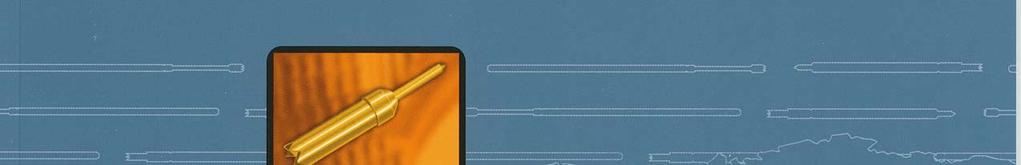
2 Testing the Limits The year is An upstart newcomer, Everett Charles Technologies, invents the first snap-out spring probe that becomes the industry standard. ISO 9001 REGISTERED COMPANY Now fast-forward to After more than 100 patented innovations, ECT continues to test the limits of test technology with innovative Pogo contacts that deliver more quality, more durability, more precision and in short more performance. The two newest examples of our continuing commitment to innovation are the PogoPlus and Semiconductor probes. Both deliver unique performance capabilities far beyond those of ordinary probes. With our continuing leadership in technical innovation, it s no wonder that after 38 years, ECT remains the first choice of test engineers and test technicians worldwide. In the future, ECT s continuing tradition of testing the limits will drive the development of tomorrow s ATE technology. Bantam series probes on the back of a U.S. penny Jam-proof plunger Ball forces plunger into continuous contact with barrel wall. PogoPlus probe shown at 3.5x magnification Semiconductor Pogos ECT offers a new line of semiconductor Pogo products, including the Double-Ended product, the new Mini-Mite series, and the Bantam series. ECT s semiconductor probes deliver high performance in compliance, with very low and consistent DC resistance. For more information, see pages or contact your ECT representative. PogoPlus The Ultimate in Consistently Low Resistance The PogoPlus Series delivers repeatably low resistance for loaded board, vacuum-fixture applications. Exclusive benefits include an enhanced bias-ball design that virtually eliminates false opens, MicroSharp tips and cutting edges, and proprietary precious metal plating processes. For details, see pages 7-11 or contact your ECT representative. 1
3 Table of Contents An Industry First Organized by Application For the fastest and most convenient access to the probe information you need, ECT is the first probe manufacturer to organize its catalog by application. Instead of hunting through the entire catalog for the information you need, all of the products and technical data for your application are in one place for easier reference and comparison. The catalog is divided into eight applications sections, each with a corresponding graphic for easy identification: Loaded PCB Test Probes Bare PCB Test Probes Wire Harness Probes Test System Interface Products High Current/High Frequency Probes Semiconductor Pogos Battery/Portable Application Probes General Purpose Probes i General Information Page Testing the Limits General Information Tip Selection Loaded PCB Test Probes Page Pogo Pogo-1 (Replaces LTP-1) Pogo-25 (Replaces EPA/HPA/SPA-25) LTP DER-050/075/ BMP-1, BMP Simply find your application in the index. Then turn to that section for a full listing of all suitable probes, arranged from smallest to largest test center. Probe technical notes that are specific to each application are located on the back of the section divider page. In cases where one probe is used for multiple applications, you may be referred to another section for product information. Plating Legend Plunger plating is color coded for easy reference. Gold plated Rhodium or Nickel plated Gold plated steel Bare PCB Test Probes Other applications Page RMP-22, MEP-22, MEPJ-22BD MEP HPA-40, MEP HPA HPA-0, SPA HPA HPA-1, SPA HPA-64, SPA EPA-2, SPA HPA FASTITE, HPA-GOLD, Biasing Ball, Cyclo-Solder MicroSharp, MiniMite,Pogo, PogoPlus, P3, Trident, Superkit, and On-Target are trademarks of Everett Charles Technologies. All information contained in this document is furnished for the sole purpose of identifying and suggesting the nature of the product involved and does not warrant the nature or quality of the product Everett Charles Technologies, Pomona, CA. All international rights preserved. Everett Charles Technologies products are covered by U.S. and foreign patents and/or pat. pend. Patent Numbers 343,802; 4,461,993; 4,720,275; D343802; 5,416,428; 5,557,213; 5,744,977; 5,641,315; 5,801,544; 29/065/622; D395,016; D400,811; D422,230; 6,396,293 and pat. pend. Specifications subject to change without notice. Consult Everett Charles Technologies for latest design changes. Dimensions in inches (millimeters). Teradyne, GenRad, Hewlett-Packard, Megatest, Schlumberger, Zehntel and Factron are trademarks or registered trademarks of their respective companies. 2
4 Wire Harness Probes Page SPL-03C-090, SPL-25J MSP-3C/5C, SSP-5C, MSP-25C Battery/Portable Application Probes Page BIP-1/2/ CCA-001/002/003/ CP Test System Interface Probes Page GSP-2B POGO-25T, POGO-25HM SIP-90, GPP General Purpose Probes Other applications Page SPA SPA SPA High Current/High Frequency Probes Page HCP-13/14/15, HCP P4301-1F Pylon K-50L, K-50L-QG, SPL-01L K-50H-S, SPL-01H CSP-03G Tools Page Tools ECT Fixtures Semiconductor Pogos Page CSP4, CSP5-18/5-20/ CSP8-15/8-20/8-25, CSP SCP-080ZB-001, SCP-100ZB-004, SCP-127ZB BTM-050/075/
5 General Information General Information The ECT Difference ECT invented the snap-out probe in It was the first replaceable spring probe available to test engineers when ATE was in its infancy. The hand-assembled probe was simple and rugged. Modern spring probes retain some fundamental attributes of the original design, but they are far more sophisticated. design evolves on CAE/CAD systems, enabling our engineers to program manufacturing equipment to optimize their designs. Custom designed machining equipment, plating processes and automatic assembly systems produce precision probes with ultra-smooth surfaces. Plunger-to-barrel tolerances are tighter. Probe tips are sharper. Springs fabricated from specially-formulated alloys maximize probe life. Quality checks are made throughout the manufacturing process using computerized statistical process controls (SPC). Final inspection ensures that the probes we ship are defect-free. Electrical Current Path and Probe Resistance Figure 1 shows that the primary current path in a probe is through the contact junction of the plunger with the barrel and the barrel with the receptacle. Secondary paths include the contact junction between the spring and plunger and the spring and barrel. Figure 2 illustrates sources of electrical resistance that must be considered. Resistance is dependent on several factors: conductivity of base metals and plating material, resistance at points of contact between components (which is affected by surface condition), area of contact, force applied at contact junctions, and probe design. For applications requiring very low, very consistent resistance, such as loaded-board test, ECT s PogoPlus probes employ an enhanced bias ball design that maintains electrical contact between the plunger and the sidewall at all times. ECT probes are self-biasing, resulting in maximum metal-to-metal contact force between components at critical contact junctions. Resistance can also be caused by such factors as: receptacle wire terminations, fixture wiring, test interface, incorrect probe selection (wrong tip, inadequate spring force), PCB surface contamination, or high-resistance contacts in the test system. Electrical resistance is included among probe specifications on each data page. Figure 1 Spring Probe and Receptacle Primary electrical current path is via contact junction of plunger with barrel (1), and barrel with receptacle (2). Secondary paths include junctions between plunger, ball and spring (3) and barrel and spring (4) Tip Plunger Barrel flush with receptacle Press ring, retains receptacle in probe plate Self-biasing for low consistent resistance Spring Detents, retains probe in receptacle Sealed for use in vacuum fixtures Several termination styles available, see fig. 3 Figure 2 Influence on Contact Resistance There are several sources of electrical resistance within the test circuit. Management of these is a prerequisite for optimizing test performance. Interface Pin or Terminal Fixture/ System Contact Junction System Pin of Probe System Internal Wiring UUT UUT/Probe Tip Contact Junction Spring Probe/ Receptacle Wire and Termination Interconnect TEST FIXTURE TEST SYSTEM To System Figure 3 Receptacle Styles Receptacles also available preterminated for easier installation. W W-1 W-2 W-3 Y W-4 4
6 Tip Selection Most tip styles can be used for a variety of different applications. Use the following chart to select appropriate tips for the feature type (pad, via, etc.) you are testing. Several tip styles will probably work for a given application, so experiment with several until you find one that provides the best performance. For testing loaded boards, tip selection factors to consider are lead length (bent or straight), surface cleanliness and pad size. In general, tips with sharp points and internal cutting edges which trap leads (such as the Trident or crown tip) are excellent choices for most loaded board requirements. In bare board applications, tips with sharp external cutting edges (such as fluted and pyramid tips) are usually best for penetrating through contamination, but these may leave marks on the contact surface. For applications where marking is undesirable, bullet nose or conical tips may be used on clean boards. A B B D B J D B J E H A B C D E Cup Point Flat Shaft Bullet Nose Conical F G H HM I G J I Self Cleaning Flat Head Cup Shaft Serrated Serrated Blade J L L18 L24/36 N N P Self Cleaning L Series Self Cleaning Radius P Crown 4-Point Crown 4-Point Crown 4-Point Needle T T1 T20 T24/36 V Self Cleaning V Self Cleaning SPA-64, HPA-64 Fluted Pyramid 3-Sided 3-Sided 3-Sided Pyramid 3-Sided TJ U UN V Z Test Jet Tri-point Trident Tulip 7-Point Crown 8-Point UN Self Cleaning Z Self Cleaning T Series tips contacting vias U Series 5

7 Loaded PCB Test Contents POGO-72 8 POGO-1 9 POGO LTP DER 50/75/ BMP-1/BMP-2 14 Other Probes that may be suited to Loaded PCB applications SPA-3 55 SPA-4 56 SPA-5 57 How to Order For each probe, specify the probe model and tip style as shown in the example below. If required, specify the optional non-standard spring force. These probes, which include the new PogoPlus Series, address the unique demands of loaded board, vacuum fixture applications. Most feature an enhanced version of the legendary bias-ball design to virtually eliminate false opens ; proprietary metal plating processes for higher conductivity; and precision MicroSharp steel tips for long-lasting durability. A full range of sizes accommodates products with mixed test center requirements. Example: POGO-25UN-2- S probe model tip style spring force steel Call to order, or fax to
8 Technical Notes SMT and Loaded Board Loaded PCB Test Probes Mixed Test Centers In loaded board applications, probes designed for use on 0.050, and inch test centers can be mixed in single or dual-stage fixtures, even though there may be minor variations in plunger travel. When mounted correctly, probe plunger tips should align when plungers are at recommended working travel generally 2/3. This will ensure contact integrity between the tip and test pad. Minor adjustments may be required to compensate for variations in accessing component leads, flat test pads or through-holes..330 (8.38) Model No.: POGO-25 Test Centers:.100 (2.54) Mounting Height: A=B=C.330 (8.38).330 (8.38) A B C POGO (1.91) A=B=C POGO (1.27) C MAX.220 (5.59) Illustration above shows 50, 75 and 100 mil probes installed in the same fixture. This is accomplished by determining the mounting height of the 100 mil probe and using the appropriate mounting height formula to establish the mounting height of the other probes. In the example, the 100 mil probe is mounted.220 inches above the probe plate. CAUTION: These are reference guidelines only. Actual mounting heights may vary among fixture designs. Loaded Board Testing Dual-Stage Application New PogoPlus Series probes Conventional bias-type probes are susceptible to false opens that is, transient electrical discontinuities that cause good products to fail during test. Revolutionary PogoPlus.004" probes eliminate probe-induced false.003 opens, saving you the time, money and.002 trouble of needless product retesting ECT Pogo contacts deliver superior pointing accuracy demonstrated by test results measuring sideload TIR. The unrivaled electrical performance of the PogoPlus is due to the interaction between the spring, captured ball and plunger, which forces the plunger into continuous contact with the barrel wall at all times. The result is uninterrupted electrical continuity and low overall resistance that can t be equaled by any other high performance probe. The PogoPlus is also designed to be the world s most durable probe with features like optional stainless-steel MicroSharp tips, a larger spring volume and enhanced pointing precision. For complete specifications and ordering information, please turn to pages How Much Better is the PogoPlus? Here s the Proof 0 Compression Displacement (Inches) Decompression PogoPlus probe Competitor s probe For dual-stage testing, component lead length should not exceed.050 inch. Resistance vs. displacement tests show the PogoPlus probe s more consistent resistivity performance resulting in significantly fewer probe false opens and tighter control of the test process Resistance (Milliohms) 7
9 High-Performance Bias Ball Probe POGO-72 Test Center.050 (1.27) Loaded PCB Test Probes POGO-72H POGO-72H-S.080 (2.03) POGO-72J POGO-72J-S POGO-72T1 POGO-72T1-S.035 (0.89) Full Radius.020 (0.50).020 (0.50).020 (0.50).330 (8.38) 1.70 (43.18) Probe Specifications POGO (6.35) POGO-72 Steel.250 (6.35) Recommended Working Travel:.167 (4.24).167 (4.24) Life Exceeds: 1 x 10 cycles 1 x 10 6 cycles Operating Temperature -55 C to +105 C -55 C to +105 C Consult factory for other temperature requirements, and applications below -40 C. Electrical (Static Conditions) Current Rating: 3 amps 3 amps maximum continuous current, non-inductive at working travel Probe Resistance 15 mω 15 mω With a standard deviation of <2 25 ma test current Ball: Receptacle Specifications Heat-treated beryllium copper, gold-plated over hard nickel Work-hardened beryllium copper, HPA-GOLD plated (I.D. and O.D.) over hard nickel Music wire Stainless steel Heat-treated tool steel, gold-plated over hard nickel Work-hardened beryllium copper, HPA-GOLD plated (I.D. and O.D.) over hard nickel Music wire Stainless steel POGO-72T20 POGO-72T20-S POGO-72T38 POGO-72T38-S.038 (0.97) 45 POGO-72U POGO-72U-S.020 (0.50).018 (0.46) Self Cleaning.020 (0.50).031 (0.78) POGO-72 Patented NOTE: To order in steel, include a -S after model #, i.e. POGO-72H-2-S Mounting Hole Size:.039 (0.99).039 (0.99) A #61 drill is most commonly used. Recommended Wire Gauge: AWG AWG Connections: HPR-72W Crimp (To order HPR-72W Crimp (To order with 30 inches of 28 or 30 with 30 inches of 28 or 30 AWG wire attached, add -28 AWG wire attached, add -28 or -30 to model number). or -30 to model number). HPR-72W-1 Solder cup HPR-72W-1 Solder cup HPR-72W-4 FASTITE wire HPR-72W-4 FASTITE wire termination (30 AWG only), termination (30 AWG only), max. insulation diameter = max. insulation diameter =.019 (0.48), wire strip.019 (0.48), wire strip length length =.125 (3.2) =.125 (3.2) DS-62-1 Insulation sleeve DS-62-1 Insulation sleeve for HPR-72-W-4. One for HPR-72-W-4. One sleeve is provided with sleeve is provided with each FASTITE receptacle each FASTITE receptacle at no charge. Consult at no charge. Consult factory for price/delivery factory for price/delivery on additional quantities. on additional quantities. FWA AWG wire FWA AWG wire with DS-62-1 insulation with DS-62-1 insulation sleeve attached. sleeve attached. Work-hardened beryllium copper, HPA-Gold plated (I.D. and O.D.) over hard nickel. Work-hardened beryllium copper, HPA-Gold plated (I.D. and O.D.) over hard nickel. Spring Force in oz. (grams) Spring Type Preload 2/3 Travel To order, add dash number to Model Number. Light (21) Standard (28) Alternate (18) High (66) Optional spring forces and materials are available. HPR-72W.024 (0.61) 2.0 (57) 4.0 (114) 6.0 (170) 8.0 (227) (4.83) (39.88).351 (8.91).038 (0.97).030 (0.76).0415 ±.0005 (1.05) HPR-72W-1 Press Ring HPR-72W (1.19) Solder Cup (Shown with DS-62-1 installed) 1.72 (43.69).0415 ±.0005 (1.05).038 (0.97).350 (8.89) FASTITE Insertion Instructions, page 67 Actual Size Dimensions in inches (millimeters) 8
10 Test Center.075 (1.91) POGO-1 High-Performance Bias Ball Probe Probe Specifications POGO-1 POGO-1 Steel POGO-1J POGO-1J-S.250 (6.35).250 (6.35) Recommended Working Travel:.167 (4.24).167 (4.24) Life Exceeds: 1 x 10 6 cycles 1 x 10 6 cycles Operating Temperature -55 C to +105 C -55 C to +105 C Consult factory for other temperature requirements, and applications below -40 C. Electrical (Static Conditions) Current Rating: 6 amps 6 amps Maximum continuous current, non-inductive at working travel Probe Resistance 10 mω 10 mω With a standard deviation of <3 25 ma test current Ball: Receptacle Specifications Heat-treated beryllium copper, gold-plated over hard nickel Work-hardened phosphor bronze, HPA-GOLD plated (I.D. and O.D.) over hard nickel Music wire Stainless steel Heat-treated tool steel, gold-plated over hard nickel Work-hardened phosphor bronze, HPA-GOLD plated (I.D. and O.D.) over hard nickel Music wire Stainless steel.025 (0.64).330 (8.38) 1.30 (33.02) POGO-1L POGO-1L-S Full Radius.024 (0.61).053 (1.34) Self.039 Cleaning (0.99) POGO-1L18 POGO-1L18-S.018 (0.46).080 (2.03) POGO-1L24 POGO-1L24-S Loaded PCB Test Probes Mounting Hole Size:.053/.055 (1.35/1.40).053/.055 (1.35/1.40) Recommended Wire Gauge: AWG AWG Connections: LTR-1W Crimp LTR-1W-1 Solder cup LTR-1W-2 Wire wrap/square post. Vacuum leak rate not to LTR-1W Crimp LTR-1W-1 Solder cup LTR-1W-2 Wire wrap/square post. Vacuum leak rate not to exceed 1 x psi exceed 1 x psi Housing: Square Post: Spring Force in oz. (grams) Spring Type Preload To order, add dash number to Model Number. Light Standard Alternate High (20) 1.47 (42) 1.73 (49) 1.20 (34) Optional spring forces and materials are available. LTR-1W When using the Amp connection, test center spacing must be increased to.100 inches. LTR-1W-1 LTR-1W (0.64) Work-hardened nickel silver, Phosphor bronze, gold plated.035 (0.89).500 (12.70).214 Min. (5.44).044 (1.12) Solder Cup 1.69 (42.93) 1.19 (30.23) Work-hardened nickel silver, Phosphor bronze, gold plated 2/3 Travel 2.0 (57) 4.0 (114) 6.0 (170) 8.0 (227) Press Ring.056 (1.42).300 (7.62) ø.052 (1.32).040 (1.02) POGO-1 Patented NOTE: To order in steel, include a -S after model #, i.e. POGO-1H-2-S POGO-1A POGO-1A-S.080 (2.03) POGO-1B POGO-1B-S POGO-1H POGO-1H-S.080 (2.03).047 (1.19).024 (0.61) POGO-1P POGO-1P-S Self Cleaning POGO-1T POGO-1T-S POGO-1T1 POGO-1T1-S POGO-1T24 POGO-1T24-S 15 POGO-1UN POGO-1UN-S.021 (0.53 ) (1.19).055 (1.40).051 (1.30).024 (0.61).020 (0.51).047 (1.19) (0.61).024 (0.61) POGO-1I POGO-1I-S (1.19) POGO-1V POGO-1V-S.054 (1.37) Self.047 Cleaning (1.19).024 (0.61) POGO-1I35-S 35 POGO-1Z POGO-1Z-S.080 (2.03).007 (0.18) Self.047 Cleaning (1.19) 9 Dimensions in inches (millimeters) Actual Size
11 High-Performance Bias Ball Probe POGO-25 Test Center.100 (2.54) Loaded PCB Test Probes POGO-25A POGO-25A-S.080 (2.03).060 (1.52) POGO-25B POGO-25B-S POGO-25FL-S POGO-25H POGO-25H-S.060 (1.52) POGO-25HM.090 (2.29).080 (2.03).122 (3.10) POGO-25I POGO-25I-S.036 (0.91).035 (0.89).036 (0.91).054 (1.37) POGO-25 Patented.330 (8.38) 1.30 (33.02) Probe Specifications POGO-25 POGO-25 Steel.250 (6.35).250 (6.35) Recommended Working Travel:.167 (4.24).167 (4.24) Life Exceeds: 1 x 10 6 cycles 1 x 10 6 cycles Operating Temperature -55 C to +105 C -55 C to +105 C Consult factory for other temperature requirements, and applications below -40 C. Electrical (Static Conditions) Current Rating: 8 amps 8 amps Maximum continuous current, non-inductive at working travel Probe Resistance 8 mω 8 mω With a standard deviation of <1 25 ma test current Ball: Receptacle Specifications Heat-treated beryllium copper, gold-plated over hard nickel Work-hardened phosphor bronze, HPA-GOLD plated (I.D. and O.D.) over hard nickel Music wire Stainless steel Mounting Hole Size:.067/.069 (1.7/1.75).067/.069 (1.7/1.75) Recommended Wire Gauge: AWG AWG Connections: SPR-25W Crimp or push-on termination (AMP terminal or equivalent) SPR-25W-1 Solder cup SPR-25W-2 Wire wrap/square post. Vacuum leak rate not to exceed 1 x psi SPR-25W-3 Connector SPR-25W Crimp or push-on termination (AMP terminal or equivalent) SPR-25W-1 Solder cup SPR-25W-2 Wire wrap/square post. Vacuum leak rate not to exceed 1 x psi SPR-25W-3 Connector pin/round post pin/round post Housing: Round Post: Square Post: Work-hardened nickel silver, Phosphor bronze, gold plated Phosphor bronze, gold plated Plunger steel, heat-treated tool, gold-plated over hard nickel Work-hardened phosphor bronze, HPA-GOLD plated (I.D. and O.D.) over hard nickel Music wire Stainless steel Work-hardened nickel silver, Phosphor bronze, gold plated Phosphor bronze, gold plated (0.91) POGO-25I35-S NOTE: To order in steel, include a -S after model #, i.e. POGO-25H-2-S Rhodium plating on plunger is available upon request (0.91) POGO-25J POGO-25J-S.025 (0.635).250 (6.35) POGO-25L POGO-25L-S Self.050 Cleaning (1.27) POGO-25L18 POGO-25L18-S.018 (0.46).150 (3.81).036 (0.91) Actual Size Green type denotes steel plunger with gold plating; PogoPlus for Stealth (no receptacles needed for use in ECT Stealth fixtures) Dimensions in inches (millimeters) 10
12 Test Center.100 (2.54) POGO-25 High-Performance Bias Ball Probe Spring Force in oz. (grams) Spring Type Preload 2/3 Travel POGO-25L36 POGO-25L36-S To order, add dash number to Model Number. Light (20) Standard (35) Alternate (49) High (61) Ultra High (53) Super (111) Optional spring forces and materials are available. SPR-25W SPR-25W (1.22).180 Min. (4.57).058 (1.47) 1.15 (29.21) 1.19 (30.23) 2.0 (57) 4.0 (114) 6.0 (170) 8.0 (227) 10.0 (283) 16.0 (455).300 (7.62).066 (1.68) 60 Self Cleaning.036 (0.91) POGO-25T POGO-25T-S POGO-25T1-S (0.81).067 (1.70).060 (1.52).036 (0.91) 30 Loaded PCB Test Probes Solder Cup Press Ring (1.78) POGO-25T36 POGO-25T36-S 15 SPR-25W (0.64) SPR-25W (0.64).500 (12.70).370 (9.40) 1.69 (42.93) 1.56 (39.62) POGO-25UN POGO-25UN-S.025 (0.64).060 (1.52).036 (0.91) POGO-25V POGO-25V-S.047 (1.19) Self.055 Cleaning (1.40).008 (0.20) POGO-25Z POGO-25Z-S Self.060 Cleaning (1.52) SPL-25H-246 (INSULATED).060 (1.52).100 (2.54).080 (2.03) 11 Dimensions in inches (millimeters) Green type denotes steel plunger with gold plating; PogoPlus for Stealth (no receptacles needed for use in ECT Stealth fixtures)
13 High-Performance, Long Travel Probe LTP-25 Test Center.100 (2.54) Loaded PCB Test Probes LTP-25A LTP-25H LTP-25L Self.050 Cleaning (1.27).080 (2.03).060 (1.52).060 (1.52) LTP-25L (2.03) Full Travel.400 (10.16).490 (12.45) 1.46 (37.08) Probe Specifications LTP (10.16) LTP-25 TJ.340 (8.6) Recommended Working Travel:.315 (8.0).315 (8.00) Operating Temperature -55 C to +105 C -55 C to +105 C Consult factory for other temperature requirements, and applications below -40 C. Electrical (Static Conditions) Current Rating: 10 amps 10 amps Maximum continuous current, non-inductive at working travel Probe Resistance 8 mω 8 mω With a standard deviation of <4 25 ma test current Ball: Receptacle Specifications Heat-treated beryllium copper, gold-plated over hard nickel Work-hardened phosphor bronze, HPA-GOLD TM plated (I.D. and O.D.) over hard nickel Music wire Stainless steel Work-hardened beryllium copper, gold-plated over hard nickel Work-hardened phosphor bronze, HPA-GOLD TM plated (I.D. and O.D.) over hard nickel Music wire Stainless steel 60 Self Cleaning LTP-25T.060 (1.52) LTP-25T36 LTP-25TJ.092 (2.34).036 (0.91) (0.91).025 (0.64).054 (1.37) LTP-25 Mounting Hole Size:.067/.069 (1.70/1.75).067/.069 (1.70/1.75) A #51 or 1.75 mm drill is most commonly used. Recommended Wire Gauge: AWG AWG Connections: SPR-25W Crimp or push-on SPR-25W Crimp or push-on termination (AMP terminal termination (AMP terminal or equivalent) or equivalent) SPR-25W-1 Solder cup SPR-25W-1 Solder cup SPR-25W-2 Wire wrap/square SPR-25W-2 Wire wrap/square post. Vacuum leak rate not post. Vacuum leak rate not to exceed 1 x 10⁻⁴ to exceed 1 x psi 15 psi SPR-25W-3 Connector SPR-25W-3 Connector pin/round post pin/round post Housing: Round Post: Square Post: Work-hardened nickel silver, Phosphor bronze, gold plated Phosphor bronze, gold plated Spring Force in oz. (grams) Spring Type Standard -4 Preload 1.24 (35).315 Travel 4.0 (114) Alternate (49) 6.0 (170) High (61) 8.0 (227) Work-hardened nickel silver, Phosphor bronze, gold plated Phosphor bronze, gold plated (0.64) 45 (1.02).145 (3.68).065 (1.65) SPR-25W SPR-25W-1 SPR-25W (42.93).025 (0.64).500 (12.70) SPR-25W (39.62).025 (0.64) Actual Size Consult factory for additional tip options. Dimensions in inches (millimeters) 12
14 Test Centers.050 (1.27).075 (1.91).100 (2.54) DER-050 DER-075 DER-100 Double-Ended Receptacles Receptacle Specifications DER-050 DER-075 DER-100 Recommended Mounting Centers: Recommended Travel: Test Height: Spring Force in oz. (grams): Overall Length:.050 (1.27).160 (4.06).130 (3.30) (40.28) 3.5 (99) (43.43).075 (1.91).160 (4.06).130 (3.30) (40.28) 3.5 (99) (43.43).100 (2.54).160 (4.06).130 (3.30) (40.28) 3.5 (99) (43.43) Recommended Mounting Hole Size:.037/.038 (.94/.97).053/.055 (1.35/1.40).067/.069 (1.70/1.75) _ Beryllium copper alloy, hard gold over nickel Beryllium copper alloy, hard gold over nickel Beryllium copper alloy, hard gold over nickel Beryllium copper alloy, hard gold over nickel Beryllium copper alloy, hard gold over nickel Beryllium copper alloy, hard gold over nickel Steel alloy, hard gold over nickel Steel alloy, hard gold over nickel Steel alloy, hard gold over nickel Receptacle: Beryllium copper alloy, Nickel silver alloy, Nickel silver alloy, hard gold over nickel hard gold over nickel hard gold over nickel _ Fixture Probes (Ordered Seperately) Probe Specifications Pogo-62 (see below) POGO-62 Pogo-1 (see page 9) Pogo-25/LTP-25 (see pages 10-12) POGO-62 Steel.300 (7.62).039 (0.99).036 (0.91).974 (24.74).170 (4.32) (39.11).300 (7.62).052 (1.32).036 (0.91).984 (24.99).170 (4.32) (39.11) Loaded PCB Test Probes Recommended Working Travel:.250 (6.35).167 (4.24).250 (6.35).167 (4.24) Life: 500,000 cycles 500,000 cycles Operating Temperature -55 C to +105 C -55 C to +105 C Consult factory for other temperature requirements, and applications below -40 C. Electrical (Static Conditions) Current Rating: 3 amps 3 amps Maximum continuous current, non-inductive at working travel Probe Resistance 15 mω 15 mω With a standard deviation of <1 25 ma test current Ball: Heat-treated beryllium copper, hard gold over nickel Work-hardened beryllium copper, hard gold over nickel Music wire Stainless steel Heat-treated beryllium copper, hard gold over nickel Work-hardened beryllium copper, hard gold over nickel Music wire Stainless steel.020 (0.51).066 (1.68) DER (7.62).998 (25.35) (39.11).020 (0.51) DER-075 B TIP STYLE Order DER-xxxB-3.5 J TIP STYLE Order DER-xxxJ-3.5 Spring Force in oz. (grams) Spring Type Preload 2/3 Travel Light -2 Standard -4 Alternate -6 POGO (14) 1.02 (29).66 (19) 2.0 (57) 4.0 (114) 6.0 (170).036 (0.91).170 (4.32) T TIP STYLE Order DER-xxxT ± (0.51) DER-100 Tip Styles H FP (Steel Only) J T T20 T38 U Dimensions in inches (millimeters)
 Red (-) BMP-1 For use in Series 32 G-10 fixtures Patent Pending Board Marker Probe The BMP-1 Board Marker Probe patented design is for installation on bare board or loaded board test fixtures.")
15 Board Marker Probes BMP-1 BMP-2 Loaded PCB Test Probes.467 (11.86) 1.91 (48.51) ± (6.35) 60 Black (+) 60 C L.025 (0.64).125 (3.18) Red (-) BMP-1 For use in Series 32 G-10 fixtures Patent Pending Board Marker Probe The BMP-1 Board Marker Probe patented design is for installation on bare board or loaded board test fixtures. When your tester is equipped with the appropriate electronics and software, the BMP-1 scribes a permanent.050 circle on every passed PCB tested. Boards that fail the test are not marked. The risk of human error is eliminated in PCB testing and sorting. The unit requires less than.500 of fixture area. It is designed to mark board areas of bare glass (FR4), solder mask over glass or copper, or bare tinned copper. The BMP-1 includes a mounting receptacle with press ring, and a motor/transmission assembly. It can be easily removed from the receptacle for use in other fixtures. Spare receptacles and tip replacement assemblies are available. The thread between receptacle and housing is 7/16-20 UNF. Consult factory for information on electronic and software requirements, and replacement receptacles and tip assemblies. Probe Specifications BMP-1 Full Marker Tip Travel:.062 (1.57) BMP (1.57).050 (1.27) CCW.050 (1.27) Recommended Working Travel:.050 (1.27) Direction of Rotation: CCW Scribed Diameter:.050 (1.27) Special diameters available. Electrical (Operating Conditions) Current Rating: 50 ma 50 ma Voltage Rating: 15VDC 15VDC Recommended Duty Cycle: 1 sec. On (min.), 5 sec. Off 1 sec. On (min.), 5 sec. Off Plunger Tip: Carbide Carbide Receptacle: Stainless steel Stainless steel Mounting Hole Size:.468/.469 (11.89/11.91).468/.469 (11.89/11.91) To Order Specify model number of components or tools you require: BMP-1, -2: Probe and receptacle, wires and connector attached, mating connector supplied, (-red, + black). BMR-1, -2: Receptacle only. BMT-1: Tip replacement assembly for both BMT-1 and BMT-2. RIT-BMP: Receptacle insertion tool for BMR-1. EXT-BMP: Receptacle extraction tool for BMR (11.86).025 (0.64).125 (3.18).112 (2.84).138 (3.50) 1.91 (48.51) ±.020 BMP-1 marker probe with receptacle. Black (+) Red (-) BMP-2 For use in Lexan Drop Pin Fixtures Patent Pending Dimensions in inches (millimeters) 14

16 15

17 Bare PCB Test Contents RMP-22/MEP-22/ 18 MEPJ-22BD MEP HPA-40/MEP HPA HPA-0/SPA-0 22 HPA HPA-1/SPA-1 24 HPA-64/SPA EPA-2/SPA-2 26 HPA How to Order For each probe, specify the probe model and tip style as shown in the example below. If required, specify the optional non-standard spring force. Example: EPA-2L-2 probe model Other applications: icons tip style spring force Drawing on more than two decades of experience in bare board electrical test, ECT offers the world s largest selection of off-the-shelf and custom probes for this application. These products have been proven in years of high-volume production, and have been continuously refined to provide the best possible performance with today s smaller feature sizes. The proven performance of these probes continues to set the industry standard for performance, reliability and value. Call to order, or fax to

18 Technical Notes Bare PCB Test Probes Replaceable probes for dedicated test fixturing for Bare PCBs such as Everett Charles Technologies series 32 Fixtures. Mixed Test Centers Figure 1 Bare Board _.050" Plunger Travel Figures 1 and 2 show how probes designed for varying test center dimensions can be mixed in the same test fixture without costly machining of the probe plate. Probes designed for or inch travel and 0.050, 0.075, and inch test centers can be mixed for bare board testing. Figure 2 Bare Board _.100" Plunger Travel 17
19 High-Performance Micro Probes RMP-22 MEP-22 MEPJ-22BD Test Center.020 (0.51) Bare PCB Test Probes.008 (0.20) dia.520 (13.21).012 (0.30) O.D..406 (10.31) Full Travel.079 (2.01) RMP-22B.598 (15.19).006 (0.15) dia.668 (16.97).013 (0.36) dia.012 (0.30) Full Travel.079 (2.01).637 (16.18).008 (0.20) I.D. MEP-22B One piece.748 (19.00).071 (1.80).670 (17.00).008 (0.21).008 (0.21).020 (0.50).430 (10.80).013 (0.32).071 (1.80) MEPJ-22BD One piece.810 (20.60) Probe Specifications Recommended Working Travel: RMP (2.01).050 (1.27) MEP (2.01).050 (1.27) MEPJ-22BD.079 (2.01).052 (1.33) Life Exceeds: 50,000 50,000 50,000 Operating Temperature -55 C to +105 C -55 C to +105 C -55 C to +105 C Consult factory for other temperature requirements, and applications below -40 C. Electrical (Static Conditions) Current Rating: 2 amps 2 amps 2 amps Maximum continuous current, non-inductive at working travel Probe Resistance 50 mω 50 mω 50 mω With a standard deviation of <4 25 ma test current Heat-treated steel, nickel boron plated Beryllium copper alloy, gold plated Music wire, gold plated Receptacle Specifications Mounting Hole Size:.016/.017 (0.41/0.43).020 (0.51) Test Centers A #77 drill is most commonly used. Heat-treated steel, nickel boron plated Beryllium copper alloy, gold plated Music wire, gold plated.0135/.014 (0.34/0.36).020 (0.51) Test Centers Heat-treated steel, nickel boron plated Phosphor bronze, gold plated Music wire, gold plated.0135/.014 (0.34/0.36).020 (0.51) Test Centers Recommended Wire Gauge: 33 AWG 33 AWG Connections: RMR-22W Crimp Crimp Double-ended probe RMR-22W-30 Crimp with 30 of 33 AWG wire attached RMR-22W-32 Crimp with 32 of 33 AWG wire attached RMR-22F Crimp, flush mounted Heat-treated beryllium Gold plated, Gold plated, copper, HPA-GOLD Phosphor bronze Phosphor bronze plated (I.D. and O.D.) over hard nickel Spring Force in oz. (grams) Spring Type Preload Recommended Force Travel in. (mm.) oz. (grams) RMP (14).05 (1.27) 1.50 (43) MEP (14).05 (1.27) 1.50 (43) MEPJ-22BD.38 (11).052 (1.27) 1.69 (48) RMR-22W.520 (13.20) RMR-22F.520 (13.20) Actual Sizes Dimensions in inches (millimeters) 18
20 Test Center.025 (0.64) MEP-20 High-Performance Micro Probe Probe Specifications MEP-20 MEP-20B.075 (1.91) Recommended Working Travel:.050 (1.27) Life Exceeds: 1 x 10 6 cycles Operating Temperature -55 C to +105 C Consult factory for other temperature requirements, and applications below -40 C. Electrical (Static Conditions) Current Rating: 2 amps Maximum continuous current, non-inductive at working travel Probe Resistance 50 mω With a standard deviation of <4 25 ma test current Heat-treated beryllium copper, gold plated over hard nickel Heat-treated beryllium copper, HPA-GOLD plated (I.D. and O.D.) over hard nickel Music wire, silver plated Receptacle Specifications Mounting Hole Size:.0205/.0215 (0.52/0.55).025 (0.635) Test Centers A #75 or 0.52 mm drill is most commonly used. Recommended Wire Gauge: 30 AWG Connections: Crimp (To order with 30 inches of 30 AWG wire attached, add -30 to model number) Shrink tubing is recommended on alternating receptacles. Order Model No. ST (0.25).023 (0.58).020 (0.51).018 (0.46).013 (0.33) I.D. MEP-20 Full Travel.075 (1.91).060 (1.52).750 (19.05) MEP-20G MEP-20J MEP-20U.010 (0.25).010 (0.25) Full Radius.010 (0.25).025 (0.64).006 (0.15).010 (0.25) Bare PCB Test Probes NOTE: The top of the MEP-20 barrel is flared, enabling it to be "press-fit" directly into the probe plate, eliminating the need for a receptacle or epoxy. This "press fit" feature also permits the MEP-20 to be installed in a variety of probe plate thicknesses and to be replaced easily. Recommended Probe plate materials are G-10 and G-11. The MEP-20 is terminated with the use of a crimp tool, which attaches a wire directly to the probe in the same fashion that a wire is attached to a crimp style receptacle. Heat-treated beryllium copper, HPA-GOLD plated (I.D. and O.D.) over hard nickel Spring Force in oz. (grams) Spring Type Preload Recommended Force Travel in. (mm.) oz. (grams) MEP (11).05 (1.27) 1.39 (39) MEP-20 Installation Application Notes for MEP The MEP-20 can also be mounted in a staggered pattern to access test pads on centers less than Recommended wire gauge 30 AWG, maximum insulation dia..019 (0.48). 3. Shrink tubing is recommended for use on alternating receptacles to reduce the possibility of electrical shorting. Order Model No. ST A probe insertion tool is available, see PIT-20, page Dimensions in inches (millimeters) Actual Size
21 High-Performance Probes HPA-40 MEP-30 Test Centers.039 (1.00).030 (0.76) Bare PCB Test Probes HPA-40J HPR-40W HPA-40B HPA-40C HPA-40G HPA-40J.550 (13.97) Full Radius.021 (0.53).021 (0.53).021 (0.53).021 (0.53).425 (10.8) Ref..390 (9.9) Ref..021 (0.53).028 (0.70) Min.125 (3.17) HPA-40 Full Travel (1.91) (2.79).021 (0.53).660 (16.76) Probe Specifications HPA (1.91) MEP (1.91) Recommended Working Travel:.050 (1.27).050 (1.27) Life Exceeds: 1 x 10 cycles 1 x 10 6 cycles Operating Temperature -55 C to +150 C -55 C to +105 C Consult factory for other temperature requirements, and applications below -40 C. Electrical (Static Conditions) Current Rating: 2 amps 2 amps Maximum continuous current, non-inductive at working travel Probe Resistance 35 mω 50 mω With a standard deviation of <4 25 ma test current Receptacle Specifications Mounting Hole Size: Spring Force in oz. (grams) Spring Type Preload Heat-treated beryllium copper, Work-hardened nickel silver, HPA-GOLD TM plated (I.D. and O.D.) over hard nickel Stainless steel, silver plated.0285/.0295 (0.72/0.75) A #69 or 0.75 mm drill is most commonly used. Recommended Wire Gauge: AWG 30 AWG Connections: HPR-40W Crimp HPR-30W Crimp (To order with 30 HPR-40T for plug-in connection inches of 30 AWG wire attached, add -30 to model number.) Work-hardened nickel silver, Heat-treated beryllium copper, HPA-GOLD plated (I.D. and HPA-GOLD plated (I.D. and O.D.) over hard nickel O.D.) over hard nickel HPA-40 as shown.79 (22) 1.75 (49) MEP-30 as shown.39 (11) 1.39 (39) Optional spring forces and materials are available. Heat-treated beryllium copper, Heat-treated beryllium copper, HPA-GOLD plated (I.D. and O.D.) over hard nickel Music wire, silver plated.0265/.0276 (0.67/0.70) A 0.70 mm drill is most commonly used. 2/3 Travel HPR-40T HPA-40 (Wire not included) Full Travel.075 (1.91) HPR-40W.022 (0.56).180 Min. (4.57) (0.76).000 MEP-30B.027 (0.69) Press Ring.390 (9.91).175 (4.45) HPR-40T.125 (3.18).250 (6.35) MEP-30G.014 (0.36).690 (17.53).390 (9.91).020 (0.51) HPR-30W MEP-30J.014 (0.36).170 Min (4.31).790 (20.10).026 (0.66) Full Radius.014 (0.36) MEP-30U.019 (0.48) (0.73) (3.05).025 (0.64).012 (0.30).014 (0.36) MEP-30 Actual Sizes Dimensions in inches (millimeters) 20 Other applications:
22 Test Center.050 (1.27) HPA-50 High-Performance Short Travel Probe Probe Specifications HPA-50 HPA-50B.050 (1.27) Recommended Working Travel:.050 (1.27) Life Exceeds: 1 x 10 6 cycles Operating Temperature -55 C to +105 C Consult factory for other temperature requirements, and applications below -40 C. Electrical (Static Conditions) Current Rating: 3 amps Maximum continuous current, non-inductive at working travel Probe Resistance 35 mω With a standard deviation of <4 25 ma test current Heat-treated beryllium copper, Work-hardened phosphor bronze, HPA-GOLD plated (I.D. and O.D.) over hard nickel Music wire, gold plated Receptacle Specifications Mounting Hole Size:.035/.0365 (0.89/0.93) A #64 or 0.92 mm drill is most commonly used. Recommended Wire Gauge: AWG Connections: SPR-0W Crimp (To order with 30 inches of 28 AWG wire attached, add -28 to model number. For 30 AWG wire, add -30 to model number.) SPR-0W-1 Solder cup SPR-0W-4 FASTITE wire termination (30 AWG only), maximum insulation diameter =.019 (0.48), wire strip length =.125 (3.2) DS-62-1 Insulation sleeve (use with SPR-0W-4) FWA AWG wire with DS-62-1 insulation sleeve attached Work-hardened nickel silver,.040 (1.02).027 (0.69) HPA-50 Full Travel.050 (1.27).590 (14.99) HPA-50D.015 (0.38).040 (1.02).012 R HPA-50G HPA-50T 45 HPA-50U.035 (0.89) Self Cleaning 3 Points.018 (0.46).021 (0.53).035 (0.89).021 (0.53).021 (0.53) Bare PCB Test Probes One DS-62-1 sleeve is provided with each SPR-0W-4 receptacle at no charge. If additional quantities are required, please contact the factory for pricing and delivery. The HPA-50 may be used to test bare PCBs on mixed test centers with the SPA-64 and HPA-52 probes, see pages 25 and 23. Spring Force in oz. (grams) Spring Type Preload Full Travel Standard 1.55 (44) as shown 3.2 (91) Optional spring forces and materials are available. SPR-0W SPR-0W (0.56).027 (0.69) Min. (17.53) (4.57).105 (2.67).034 (0.86) Solder Cup SPR-0W-4 (Shown with DS-62-1 installed).795 (20.19) Press Ring (0.94).047 (1.19).350 (8.89) FASTITE Insertion Instructions, page (2.54) 21 Dimensions in inches (millimeters) Actual Size
23 High-Performance & Standard Probes HPA-0 SPA-0 Test Center.050 (1.27) Bare PCB Test Probes HPA-0A SPA-0A HPA-0B SPA-0B HPA-0D SPA-0D HPA-0G12 SPA-0G12 HPA-0G21 SPA-0G21 HPA-OH SPA-OH HPA-0J SPA-0J HPA-0L SPA-0L Self Cleaning HPA-0T SPA-0T.035 (0.89).035 (0.89).021 (0.53).035 (0.89).015 (0.38).012 (0.31).035 (0.89) Full Radius.035 (0.89).035 (0.89) (0.53).021 (0.53).021 (0.53).021 (0.53).021 (0.53).021 (0.53).021 (0.53).027 (0.69).027 (0.69).035 (0.89).035 (0.89) HPA-0 Full Travel:.100 (2.54) Full Travel:.100 (2.54).635 (16.13).635 (16.13) Probe Specifications HPA (2.54) SPA (2.54) Recommended Working Travel:.067 (1.70).067 (1.70) Life Exceeds: 1 x 10 cycles 1 x 10 6 cycles Operating Temperature Standard spring: Alternate spring: -55 C to +150 C -55 C to +105 C -55 C to +150 C -55 C to +105 C Consult factory for other temperature requirements, and applications below -40 C. Electrical (Static Conditions) Current Rating: 3 amps 3 amps Maximum continuous current, non-inductive at working travel Probe Resistance 35 mω 50 mω With a standard deviation of: <5 25 ma test current <7 25 ma test current Standard: Alternate: One DS-62-1 sleeve is provided with each SPR-0W-4 receptacle at no charge. If additional quantities are required, please contact the factory for pricing and delivery. The HPA-0 and SPA-0 may be used to test bare PCBs on mixed test centers with the HPA-1 and HPA-74 probes, see pages 24 and 27. Spring Force in oz. (grams) Spring Type Preload To order, add dash number to Model Number. Standard as shown.61 (17) Alternate (22) Optional spring forces and materials are available. SPR-0W SPR-0W-1 Heat-treated beryllium copper, Work-hardened phosphor bronze, HPA-GOLD plated (I.D. and O.D.) over hard nickel Stainless steel, silver plated Music wire, silver plated Receptacle Specifications Mounting Hole Size:.035/.0365 (0.89/0.93).035/.0365 (0.89/0.93) A #64 or 0.92 mm drill is most commonly used. Recommended Wire Gauge: AWG AWG Connections: SPR-0W Crimp (To order with SPR-0W Crimp (To order with 30 inches of 28 AWG wire 30 inches of 28 AWG wire attached, add -28 to model attached, add -28 to model number. For 30 AWG wire, number. For 30 AWG wire, add -30 to model number.) add -30 to model number.) SPR-0W-1 Solder cup SPR-0W-1 Solder cup SPR-0W-4 FASTITE wire SPR-0W-4 FASTITE wire termination (30 AWG only), termination (30 AWG only), maximum insulation maximum insulation diameter.019 (0.48), wire diameter.019 (0.48), wire strip length =.125 (3.2) strip length =.125 (3.2) DS-62-1 Insulation sleeve (use DS-62-1 Insulation sleeve (use with SPR-0W-4) with SPR-0W-4) FWA AWG wire with FWA AWG wire with DS-62-1 insulation sleeve DS-62-1 insulation sleeve attached attached.022 (0.56) Solder Cup Work-hardened nickel silver,.027 (0.69) SPR-0W-4 (Shown with DS-62-1 installed).795 (20.19) Heat-treated beryllium copper, rhodium plated over hard nickel Work-hardened phosphor bronze, HPA-GOLD plated (I.D. and O.D.) over hard nickel Stainless steel, silver plated Music wire, silver plated Work-hardened nickel silver, 2/3 Travel 2.8 (79) 3.7 (105) Min. (17.53) (4.57).105 (2.67) Press Ring (0.94).034 (0.86) Actual Sizes SPA-0 Dimensions in inches (millimeters) (1.19).350 (8.89) FASTITE Insertion Instructions, page (2.54) Other applications:
24 Test Center.075 (1.91) HPA-52 High-Performance Short Travel Probe Probe Specifications HPA (1.91) Recommended Working Travel:.075 (1.91) Life Exceeds:.250 x 10 6 cycles Operating Temperature -55 C to +150 C Consult factory for other temperature requirements, and applications below -40 C. Electrical (Static Conditions) Current Rating: 3 amps Maximum continuous current, non-inductive at working travel Probe Resistance 15 mω With a standard deviation of <5 25 ma test current Receptacle Specifications Mounting Hole Size:.053/.055 (1.35/1.40) A #54 or 1.44 mm drill is most commonly used. Recommended Wire Gauge: AWG Connections: SPR-1W Crimp SPR-1W-1 Solder cup SPR-1W-2/SPR-1W-2M Wire wrap/square post. Vacuum leak rate not to exceed 1 x psi Housing: Square Post: Heat-treated beryllium copper, Work-hardened phosphor bronze, HPA-GOLD plated (I.D. and O.D.) over hard nickel Stainless steel, silver plated Work-hardened nickel silver, Phosphorous bronze, gold plated Full Travel.075 (1.91).060 (1.52).040 (1.02) HPA (15.98) HPA-52B HPA-52D.040 (1.02) HPA-52T.039 (0.99).021 (0.53).021 (0.53).057 (1.45) Bare PCB Test Probes Spring Force in oz. (grams) Spring Type Preload 3/4 Travel To order, add dash number to Model Number. Standard as shown 1.68 (48) Alternate (72) Optional spring forces and materials are available (91) 6.2 (176) SPR-1W SPR-1W (0.89).180 Min. (4.57).044 (1.12).690 (17.53).160 (4.06).052 (1.32) SPR-1W-2 Solder Cup Press Ring (1.42) 1.06 (26.92).025 (0.64) SPR-1W-2M.500 (12.70).940 (23.88).025 (0.64).250 (6.35) 23 Dimensions in inches (millimeters) Actual Size
25 High & Standard Performance Probes HPA-1 SPA-1 Test Center.075 (1.91) Bare PCB Test Probes HPA-1A SPA-1A HPA-1B SPA-1B HPA-1C SPA-1C HPA-1D SPA-1D.040 (1.02).060 (1.52) HPA-1E SPA-1E.021 (0.53).060 (1.52).021 (0.53).060 (1.52).021 (0.53).040 (1.02).060 (1.52) HPA-1 Full Travel:.100 (2.54).655 (16.64) Probe Specifications HPA (2.54) SPA (2.54) Recommended Working Travel:.067 (1.70).067 (1.70) Life Exceeds: 1 x 10 cycles 1 x 10 6 cycles Operating Temperature -55 C to +150 C -55 C to +150 C Consult factory for other temperature requirements, and applications below -40 C. Electrical (Static Conditions) Current Rating: 3 amps 3 amps Maximum continuous current, non-inductive at working travel Probe Resistance 35 mω 50 mω With a standard deviation of <7 25 ma test current Receptacle Specifications Mounting Hole Size:.053/.055 (1.35/1.40).053/.055 (1.35/1.40) A #54 or 1.4 mm drill is most commonly used. Housing: Square Post: Heat-treated beryllium copper, Work-hardened phosphor bronze, HPA-GOLD plated (I.D. and O.D.) over hard nickel Stainless steel, silver plated Recommended Wire Gauge: AWG AWG Connections: SPR-1W Crimp SPR-1W Crimp SPR-1W-1 Solder cup SPR-1W-1 Solder cup SPR-1W-2/SPR-1W-2M Wire SPR-1W-2/SPR-1W-2M Wire wrap/square post. Vacuum wrap/square post. Vacuum leak rate not to exceed leak rate not to exceed 1 x psi 1 x psi Work-hardened nickel silver, Phosphorous bronze, gold plated Heat-treated beryllium copper, rhodium plated over hard nickel Work-hardened phosphor bronze, HPA-GOLD plated (I.D. and O.D.) over hard nickel Stainless steel, silver plated Work-hardened nickel silver, Phosphorous bronze, gold plated HPA-1F SPA-1F The HPA-1 and SPA-1 may be used to test bare PCBs on mixed test centers with the HPA-0 and HPA-74 probes, see pages 22 and 27. Spring Force in oz. (grams) Spring Type Preload 2/3 Travel HPA-1G SPA-1G HPA-1H SPA-1H.060 (1.52).021 (0.53).060 (1.52) Full Travel:.100 (2.54) To order, add dash number to Model Number. Standard as shown 1.1 (31) Alternate (37) Optional spring forces and materials are available. SPR-1W SPR-1W (0.89).180 Min. (4.57).044 (1.12).690 (17.53) 2.5 (71) 4.5 (128).160 (4.06).052 (1.32) HPA-1J SPA-1J.060 (1.52).655 (16.64) SPR-1W-2 Solder Cup 1.06 (26.92) Press Ring (1.42) Full Radius HPA-1T SPA-1T.021 (0.53).040 (1.02).025 (0.64) SPR-1W-2M.500 (12.70).940 (23.88).025 (0.64).057 (1.45).250 (6.35) Actual Sizes SPA-1 Dimensions in inches (millimeters) 24
26 Test Centers.100 (2.54).125 (3.18).156 (3.96).187 (4.75) Probe Specifications HPA (1.27) Recommended Working Travel:.050 (1.27) Life Exceeds: 1 x 10 6 cycles HPA-64 SPA-64 1 x 10 6 cycles Operating Temperature -55 C to +150 C -55 C to +150 C Consult factory for other temperature requirements, and applications below -40 C. Electrical (Static Conditions) Current Rating: 3 amps 3 amps Maximum continuous current, non-inductive at working travel Probe Resistance 50 mω 50 mω With a standard deviation of <8 25 ma test current Heat-treated beryllium copper, Work-hardened nickel silver Stainless steel, silver plated SPA (1.27).050 (1.27) Heat-treated beryllium copper, Work-hardened nickel silver Stainless steel, silver plated Receptacle Specifications Mounting Hole Size:.067/.069 (1.7/1.75).067/.069 (1.7/1.75) A #51 or 1.75 mm drill is most commonly used. Recommended Wire Gauge: AWG AWG Connections: SPR-64W-2 Wire wrap/square SPR-64W-2 Wire wrap/square post, 100% vacuum sealed post, 100% vacuum sealed Nickel silver alloy Nickel silver alloy Hole Diameters to be Contacted HPA/SPA-64-1 HPA/SPA-64-2 HPA/SPA-64-3 HPA/SPA-64-4 HPA/SPA-64-7 HPA/SPA-64-8 HPA/SPA-64-9 HPA/SPA up to.073 (1.85) lands and pads lands and pads up to.058 (1.47) up to.150 (3.81) up to.070 (1.78) lands and pads lands and pads up to.073 (1.85) lands and pads lands and pads up to.058 (1.47) up to.150 (3.81) up to.070 (1.78) lands and pads lands and pads.285 (7.24) Full Travel:.050 (1.27).055 (1.40) HPA-64 Standard-Performance Probes A See Chart.077 (1.96) HPA-64-1 SPA (3.96).077 (1.96) HPA-64-2 SPA ( ) HPA-64-3 SPA (1.96) HPA-64-4 SPA (1.65) HPA-64-7 SPA (1.905).040 (1.02).028 (0.71).028 (0.71) Spherical Radius Bare PCB Test Probes The SPA-64W-2 can be used to test bare PCBs on Mixed test centers with the HPA-50 and HPA-52, see pages 21 and 23. Spring Force in oz. (grams) Spring Type Preload Full Travel HPA-64-8 SPA (1.27) Standard as shown 1.1 (31) Optional spring forces and materials are available. Recommended Test Centers HPA/SPA-64-1, -2, -3, -4, -8, -9, (2.54) HPA/SPA (4.75) Model No. Overall Length (Dimension A) SPA-64-1, -4, -7 SPA-64-2, -3 SPA-64-8 SPA-64-9, (9.53).365 (9.27).385 (9.78).363 (9.22) SPR-64W (20.83).410 (10.41).025 (0.64) (Two Level Wrap).065 (1.65) (1.80) (110).005 (0.127).076 (1.92).285 (7.24) Full Travel:.050 (1.27) A See Chart.075 (1.91) HPA-64-9 SPA (1.19) HPA SPA (1.19) Full Radius.028 (0.71).055 (1.40) SPA-64 Other applications: 25 Dimensions in inches (millimeters) Actual Size
27 Standard-Performance Probes EPA-2 SPA-2 Test Center.100 (2.54) Bare PCB Test Probes.030 (0.76).030 (0.76) EPA-2A SPA-2A.080 (2.03).075 (1.91) EPA-2B30 SPA-2B (3.30).030 (0.76) EPA-2B40 SPA-2B (1.02) EPA-2C30 SPA-2C (3.30) EPA-2C40 SPA-2C (1.27).040 (1.02).075 (1.91).075 (1.91).130 (3.30).040 (1.02) EPA-2D SPA-2D EPA-2E SPA-2E.040 (1.02) EPA-2F SPA-2F EPA-2G30 SPA-2G30 EPA-2G40 SPA-2G (2.03).054 (1.37) EPA-2 Full Travel:.160 (4.06) EPA-2J30 SPA-2J (0.76) EPA-2J40 SPA-2J40 EPA-2L SPA-2L Self.050 Cleaning (1.27) EPA-2P SPA-2P Self Cleaning EPA-2T SPA-2T.970 (24.64).130 (3.30).075 (1.91).040 (1.02).060 (1.52).080 (2.03).054 (1.37) SPA-2 Full Travel:.160 (4.06).970 (24.64) Probe Specifications EPA (4.06) SPA (4.06) Recommended Working Travel:.107 (2.72).107 (2.72) Life Exceeds: 2 x 10 cycles 2 x 10 6 cycles Operating Temperature -55 C to +105 C -55 C to +105 C Consult factory for other temperature requirements, and applications below -40 C. Electrical (Static Conditions) Current Rating: 5 amps 5 amps Maximum continuous current, non-inductive at working travel Probe Resistance 35 mω 50 mω With a standard deviation of: <5 25 ma test current <7 25 ma test current Receptacle Specifications Mounting Hole Size:.067/.069 (1.7/1.75).067/.069 (1.7/1.75) A #51 or 1.75 mm drill is most commonly used. Housing: Round Post: Square Post: PE Series: Dimensionally identical to EPA-2. The PE Series replaceable probe has a slight bulge at the end of the barrel and is designed for use in receptacles lacking detents. To order, write the letter P after the model number. Example: EPA-2P, EPA-2AP-1. Spring Force in oz. (grams) Spring Type Preload To order, add dash number to Model Number. Standard as shown 1.08 (31) Alternate (75) Ultra High (116) Optional spring forces and materials are available. SPR-2W SPR-2W-1 SPR-2W-2 Heat-treated beryllium copper, Work-hardened nickel silver, gold plated (I.D. and O.D.) over hard nickel Music wire, silver plated Recommended Wire Gauge: AWG AWG Connections: SPR-2W Crimp or push on SPR-2W Crimp or push on termination (AMP terminal termination (AMP terminal or equivalent) or equivalent) SPR-2W-1 Solder cup SPR-2W-1 Solder cup SPR-2W-2 Wire wrap/square SPR-2W-2 Wire wrap/square post. Vacuum leak rate not post. Vacuum leak rate not to to exceed 1 x exceed 1 x psi psi SPR-2W-3 Connector pin/ SPR-2W-3 Connector pin/ round post round post SPR-2Y push on termination SPR-2Y push on termination.025 (0.64).048 (1.22).500 (12.70) Work-hardened nickel silver, Phosphor bronze, gold plated Phosphor bronze, gold plated.20 Min. (5.08).058 (1.47) Solder Cup 1.45 (36.83).930 (23.62).950 (24.13) Heat-treated beryllium copper, rhodium plated over hard nickel Work-hardened nickel silver, gold plated (I.D. and O.D.) over hard nickel Music wire, silver plated Work-hardened nickel silver, Phosphor bronze, gold plated Phosphor bronze, gold plated 2/3 Travel 3.5 (99) 6.5 (184) 10.0 (283).240 (6.10) Press Ring (1.78).066 (1.68).040 (1.02).075 (1.91) SPR-2W (33.53) Actual Sizes EPA-2H SPA-2H.075 (1.91) EPA-2X SPA-2X Self Cleaning.025 (0.64).065 (1.65).060 (1.52) Dimensions in inches (millimeters) SPR-2Y (0.64).735 (18.67)
28 Test Centers.100 (2.54).156 (3.96).187 (4.75) HPA-74 High-Performance Long-Travel Probe Probe Specifications HPA (2.54) Recommended Working Travel:.075 (1.91) Life Exceeds: 2 x 10 6 cycles Operating Temperature -55 C to +105 C Consult factory for other temperature requirements, and applications below -40 C. Electrical (Static Conditions) Current Rating: 3 amps Maximum continuous current, non-inductive at working travel Probe Resistance 35 mω With a standard deviation of <5 25 ma test current Alt Heat-treated beryllium copper, Phosphor bronze, HPA-GOLD TM plated (I.D. and O.D.) over hard nickel Stainless steel, silver plated Music wire, silver plated Receptacle Specifications Mounting Hole Size:.067/.069 (1.7/1.75) A #51 or 1.75 mm drill is most commonly used. Recommended Wire Gauge: AWG Connections: EPR-74W-2 Wire wrap/square post, 100% vacuum sealed Nickel silver alloy Hole Diameters to be Contacted HPA-74A lands and pads HPA-74B lands and pads HPA-74C lands and pads HPA-74E up to.073 (1.85) HPA-74T65 up to.058 (1.47) HPA-74T75 up to.070 (1.78) HPA-74T80 up to.073 (1.85) HPA-74T135 up to.125 (3.18) HPA-74T156 up to.150 (3.81) Full Travel:.100 (2.54).470 (11.94).053 (1.35) HPA (14.48) HPA-74A.080 (2.03) HPA-74B HPA-74C HPA-74E.045 (1.14).041 (1.04).041 (1.04).080 (2.03) HPA-74T (1.65) HPA-74T (1.91) HPA-74T (2.03).025 (0.64).028 (0.71) =.598 (15.19) =.586 (14.88).050 (1.27).040 (1.016) Bare PCB Test Probes The HPA-74 can be used to test bare PCBs on Mixed test centers with the HPA-0 and HPA-1, see pages 22 and 24. Spring Force in oz. (grams) Spring Type Preload 3/4 Travel To order, add dash number to Model Number. Standard as shown 1.71 (48) 3.0 (85) Alternate (80) 5.0 (141) Optional spring forces and materials are available. Recommended Test Centers HPA-74T (3.43) HPA-74T156 HPA-74A, B, C, E, T65, T75, T80 HPA-74T135 HPA-74T (2.54).156 (3.96).187 (4.75).156 (3.96) EPR-74W (22.86).365 (9.27).007 (0.178).025 (0.64) (Two Level Wrap).064 (1.63) (1.80) Dimensions in inches (millimeters) Actual Size
29 28

30 Wire Harness A 15-year history of providing wire harness test probe solutions has made ECT the largest supplier of probes to North American automotive and major appliance manufacturers. Expert engineering support, from the early stages of design through high volume production, assures you ll get reliable test solutions for continuity testing, push testing, presence checking, terminal push-out and other wire harness test applications. Contents SPL-03C-090/ 30 SPL-25J-289 MSP 3C/5C, SSP-5C, 31 MSP-25C Other Probes that may be suited to Bare PCB applications SPA-3 55 SPA-4 56 SPA-5 57 How to Order To order from this section, specify actual part number. Example: SPL-03C-090 probe model Call to order, or fax to
31 High-Performance Anti-Walkout Design Probes SPL-03C-090 SPL-25J-289 Test Centers.125 (3.18).100 (2.54).030 inside (0.76).040 (1.02) dia dia Press ring dia. ( ) One-piece design, no receptacle required.050 (1.27) dia. outside.330 (8.38).300 (7.62).041 (1.04) dia dia ( ) Press ring dia.350 (8.89).300 (7.62) Probe Specifications Recommended Working Travel: SPL-03C (5.59).220 (5.59) SPL-25J (5.92).233 (5.92) Life Exceeds: 1 x 10 cycles 1 x 10 6 cycles Operating Temperature -55 C to +105 C -55 C to +105 C Consult factory for other temperature requirements, and applications below -40 C. Electrical (Static Conditions) 5 amps 5 amps Current Rating: Probe Resistance 50 mω 50 mω Ball: Spring Force in oz. (grams) Spring Type SPL-03C-090 as shown Preload.77 (22) SPL as shown.25 (7) Beryllium copper, gold plated Nickel silver, gold plated Music wire, silver plated Brass, gold plated Beryllium copper, gold plated Nickel silver, gold plated Music wire, silver plated Stainless steel, gold plated.220 Travel.233 Travel 2.30 (65) 1.16 (33) Wire Harness Probes.093 (2.36) 1.53 (38.86).066 (1.68) 1.50 (38.10).058 (1.47) I.D..021 (0.53) I.D. SPL-03C-090 SPL-25J-289 Actual Sizes Note: SPL prefix represents non-standard probes, please consult factory, lead times may vary. Dimensions in inches (millimeters) 30
32 Test Centers.125/187 (3.18/4.75).187 (4.75).100 (2.54) MSP 3C/5C SSP-5C MSP-25C Standard Momentary Switch Probes Probe Specifications MSP-3C MSP-5C MSP-25C SSP-5C Full Travel (+/-.010):.140 (3.56) Recommended Travel:.085 (2.16).185 (4.70).132 (3.35).125 (3.18).085 (2.16).150 (3.81).100 (2.54) Life: 100K cycles 100K cycles 100K cycles 100K cycles Switch Point: (+/-.012) Electrical.030 (0.76).025 (0.64).030 (0.76).025 (0.64) Maximum Current Rating (Non-inductive DC) 3 amps 5 amps 3 amps 5 amps Average Probe Resistance 50 mω 20 mω 50 mω 50 mω Nickel plated Beryllium copper Silver plated Nickel silver Insulator: Terminal: Silver plated Stainless steel KEL-F Silver plated Beryllium copper Nickel plated Brass Silver plated Brass Spring Force in oz. (grams) Spring Type MSP-3C MSP-5C MSP-25C SSP-5C Switch Recommended Travel: Switch Recommended 3.2 (90) 7.5 (213) 24.8 (703) 2.5 (70) 5.2 (146) 26.9 (755) 6.51 (183) 7.55 (212) 2.36 (66) 4.5 (126) Travel: 35.0 (992) 35.0 (992) TIp Styles: C C C C Optional tip styles, spring forces and plating are available. SPR-3W For use with MSP-3C Materials: Gold plated nickel silver Mounting Hole:.094/.096 (2.39/2.44) Quick disconnect for replacement ease: Newark Part # SPR-5W For use with MSP-5C Materials: Gold plated nickel silver Mounting Hole:.141/.143 (3.58/3.63) Quick disconnect for replacement ease: Amp Part # SSR-5Y For use with SSP-5C Materials: Gold plated nickel silver Mounting Hole:.141/.143 (3.58/3.63 I.D..047 O.D. (1.19).058 (1.47) I.D..079 O.D. (2.01).093 (2.36) Silver plated Music wire KEL-F Silver plated Brass.180 Min (4.57).180 Min (4.57) Nickel plated Beryllium copper Work-hardened phosphor bronze, HPA-GOLD plated (I.D. and O.D.) over hard nickel Silver plated Music wire DELRIN Silver plated Beryllium copper 1.20 (30.48) 1.32 (33.53).095 (2.41) I.D..140 (3.56) Gold plated Beryllium copper Silver plated Nickel silver Silver plated Spring steel DELRIN Gold plated Beryllium copper.300 (7.62).300 (7.62).656 (16.66).630 (16.00).475 (12.06).093 (2.36).140 (3.56).270 (6.86) Press Ring.144 (3.66) Applications A switch probe is designed primarily for presence/electrical test applications such as detecting the absence or presence of contacts within a wire harness connector. In this case, the switch probe provides electrical interconnection and verifies the connector has been manufactured properly.; If contacts are missing or out of place, the part is rejected. If all the contacts are in place, the part is accepted and an electrical test is performed, verifying electrical integrity of the connector and the wires within the harness (54.50).350 (8.89) +/ (7.49).250 (6.35) +/ (30.73).279 (7.08) MSP-3C SSP-5C.060 (1.52).050 (1.27) Shaft Only.080 (2.03).032 (0.81).040 (1.02).060 (1.52) Shaft Only.125 (3.18) Insulator.060 (1.52).035 (0.89).350 (8.89).038 (0.97).072 (1.83) 1.15 (29.21) 2.26 (57.40).250 (6.35) +/ (8.38).060 (1.52) Shaft Only.126 (3.20) Insulator.060 (1.52) MSP-5C*.330 (8.38) +/ (42.93).150 (3.81).041 (1.04).080 (2.02).034 (0.86) Shaft Only.054 (1.37).020 (0.508) MSP-25C CAPS FOR MSP-3C/5C*.055 (1.40).055 (1.40).055 (1.40).290 (7.37).140 (3.56) PE (7.37).140 (3.56) PE (7.37).140 (3.56).140 (3.56).200 (5.08).395 (10.03) 30 PE-3 * When the MSP-5C is used with caps, full travel is.150 Wire Harness Probes SPR-25W For use with MSP-25C Materials: Gold plated nickel silver Mounting Hole:.067/.069 (1.70/1.75) Quick disconnect for replacement ease: Newark Part #87269 I.D..039 (0.99) O.D..050 (1.27).180 Min (4.57) 1.19 (30.23).300 (7.62) Press Ring.072 (1.83).066 (1.68) SSP PRESENCE DETECTION DEVICE Replaceable mechanical switch easily and reliably detects part presence and/or orientation. Quick-Connect termination. Tip material: Black Phenol IC 31 Dimensions in inches (millimeters)
33 32

34 Test System Interface ECT is your source for interface probes for all major brands of test systems, including Teradyne, GenRad and Hewlett-Packard. In fact, two of these companies specify ECT probes as original equipment. If our standard products don t meet your requirements, contact Everett Charles Technologies for expert assistance in designing and manufacturing your custom interface probe. Contents FRP-25T/GSP-2B 34 POGO-25T/POGO-25HM 35 SIP-90/GPP How to Order To order from this section, specify actual part number. Example: FRP-25T probe model Other applications: icons Call to order, or fax to
35 ATE Receiver Probe GSP-2B Test Center.100 (2.54).041 (1.04) Probe Specifications GSP-2B GSP-2B Full Travel:.125 (3.18).845 (21.46) Application: The GSP-2B is designed for use in GenRad tester interfaces.125 (3.18) Operating Temperature: -55 C to C Consult factory for other temperature requirements, and applications below -40 C. Electrical (Static Conditions) Current Rating: 5 amps Maximum continuous current, non-inductive at working travel Probe Resistance: 35 mω With a standard deviation of <5 25 ma test current Heat-treated beryllium copper, Work-hardened nickel silver, gold plated (I.D. and O.D.) over hard nickel Beryllium copper, silver plated Receptacle Specifications See SPR-2 series specifications, page (1.37) Spring Force in oz. (grams) Spring Type Preload 3/4 Travel Test System Interface Probes GSP-2B For GenRad 227/82/73 To order, add dash number to Model Number. GSP-2B as shown 2.0 (57) Optional spring forces and materials are available. W-2 W-3 Y.025 (0.64).025 (0.64) Receptacle Dimensions A B C D E SPR-2W.930(23.62).066(1.68).048(1.22).058(1.47).20(5.08) SPR-2W-1.950(24.13).066(1.68).048(1.22).058(1.47).20(5.08) SPR-2W (36.83).066(1.68) Square Post =.025(0.064) SPR-2W (33.53).066(1.68) Round Post =.025(0.064) DIA. SPR-2Y.735(18.67).066(1.68) A A 4.5 (128) H B SPR-2 Series press ring diameter is typically.070 (1.78) H dimension SPR-2 Series =.240 (6.09) Actual Size Note: The GSP-2BP is designed for use in receptacles without detents. Dimensions in inches (millimeters) 34
36 Test Center.100 (2.54) POGO-25T POGO-25HM Agilent/HP 3070 & Teradyne 800/1800 Receiver Probes.060 (1.50) Probe Specifications POGO-25T POGO-25HM POGO-25T.250 (6.35).250 (6.35) Recommended Working Travel:.167 (4.24).167 (4.24) Life Exceeds: 2 x 10 cycles 2 x 10 6 cycles Operating Temperature -55 C to +105 C -55 C to +105 C Consult factory for other temperature requirements, and applications below -40 C. Electrical (Static Conditions) Current Rating: 10 amps 10 amps Maximum continuous current, non-inductive at working travel Probe Resistance 8 mω 8 mω With a standard deviation of: <1 25 ma test current <4 25 ma test current Ball: Heat-treated beryllium copper, gold-plated over hard nickel Work-hardened phosphor bronze, HPA-GOLD plated (I.D. and O.D.) over hard nickel Music wire Stainless steel Heat-treated beryllium copper, gold-plated over hard nickel Work-hardened phosphor bronze, gold plated (I.D. and O.D.) over hard nickel Music wire Stainless steel.080 (2.03) Full Travel:.250 (6.35) 1.30 (33.02).060 (1.52) 30 Spring Force in oz. (grams) Spring Type Preload 2/3 Travel To order, add dash number to Model Number. Standard (35) Optional spring forces and materials are available. 4.0 (114).054 (1.37).020 (0.51).080 (2.03) POGO-25T For Teradyne 800/ (2.29) dia..122 (3.10) dia..330 (8.38) POGO-25HM.090 (2.29).080 (2.03).122 (3.10) Test System Interface Probes 1.30 (33.02).054 (1.37) POGO-25HM For Agilent/HP Dimensions in inches (millimeters) Actual Sizes
37 ATE Interface Pins SIP-90 GPP-95-2 Test Center.100 (2.54) SIP-90-2 Materials: Brass, gold plated Mounting Hole Size:.055 (1.40) Applications: Designed for use in original GenRad interface blocks. SIP-90-3 Materials: Brass, gold plated Mounting Hole Size:.055 (1.40) Applications: Designed for use in original Zehntel interface panels. SIP-90-4 Materials: Brass, gold plated Mounting Hole Size:.055 (1.40) Applications: Designed for use in original Factron interface panels. SIP-90-4 replaces SIP GPP-95-2 Materials: Brass, gold plated Mounting Hole Size:.085 (2.15) Applications: Designed for use in original GenRad interface boards. Test System Interface Probes SIP-90-5 Materials: Brass, gold plated Mounting Hole Size:.057 (1.45) Applications: General interconnect. SIP-90-6 Materials: Brass, gold plated Mounting Hole Size:.057 (1.45) Applications: General interconnect. SIP-90-7 Materials: Brass, gold plated Mounting Hole Size:.0595 (1.51) Applications: General interconnect. Dimensions in inches (millimeters) 36
38 High Current High Frequency For powered functional testing of connectors, wire harnesses, modules and other devices drawing up to 45A, our high current probes feature low resistance plungers and multiple-point, high-current-capacity tips. Only Everett Charles Technologies offers a complete line of high current probes for.100,.125 and.187-inch test centers. And only Everett Charles Technologies provides direct technical support to help you make the most of them. Contents HCP-13/14/15/HCP P4301-1F Pylon 40 K-50L/K-50L-QG 41 K-50H-S 42 CSP-03G How to Order To order from this section, specify actual part number. Example: K-50L probe model Call to order, or fax to
 at working travel. While this is sufficient for most board test applications, higher current probes are sometimes required.")
39 Technical Notes High Current/High Frequency Probes The maximum continuous current rating of a spring probe is determined by its design, size and construction. probes are rated from 2 to 5 amps maximum current (non-inductive) at working travel. While this is sufficient for most board test applications, higher current probes are sometimes required. ECT High-Current Probes (HCP series) are capable of carrying electrical current up to 45 amps. 38
40 Test Centers.100 (2.54).125 (3.18).187 (4.75) HCP-13/14/15 HCP-25 High-Current Probes Probe Specifications Recommended Working Travel: Life Exceeds:.250 (6.35).250 (6.35).167 (4.24).167 (4.24).25 x 10 cycles.5 x 10 6 cycles Operating Temperature -55 C to +150 C -55 C to +150 C Consult factory for other temperature requirements, and applications below -40 C. Electrical (Static Conditions) Current Rating: HCP-13 HCP-14 HCP-15 HCP amps Maximum continuous current, non-inductive at working travel Probe Resistance 25 mω 25 mω With a standard deviation of: <3 25 ma test current <5 25 ma test current Ball: HCP-13, 14, amps 25 amps 35 amps Heat-treated beryllium copper, Work-hardened nickel silver, silver plated (I.D. and O.D.) over hard nickel Stainless steel, silver plated Brass, gold plated HCP-25 Heat-treated beryllium copper, Work-hardened phosphor bronze, silver plated (I.D. and O.D.) over hard nickel Stainless steel, silver plated Stainless steel.010 (0.25) Radius Min. D C B HCP-13A HCP-14A HCP-15A HCP-25A HCP-13B HCP-14B HCP-15B 60 HCP-25B F E.010 (0.25) Radius Min..010 (0.25) Radius Min. Receptacle Specifications Use SPR Series: HCP-13 HCP-14 HCP-15 HCP-25 SPR-3 series (page 55) SPR-4 series (page 56) SPR-5 series (page 57) SPR-25 series (page 11) NOTE: The wire gauge listed on the referenced pages is for typical ATE applications only. Larger wire size may be required for other applications. Spring Force in oz. (grams) Spring Type Preload 2/3 Travel HCP (44) 4.5 (128) HCP (24) 4.8 (128) HCP-15 HCP (107) 0.86 (24) 16.0 (456) 4.0 (114) Optional spring forces and tip styles are available for the HCP-25. A D HCP-13 HCP-14 HCP-15 C B HCP-13H HCP-14H HCP-15H HCP-25H HCP-13P Probe Dimensions HCP-13 HCP-14 Test Centers.125 (3.18).187 (4.75) A.080 (2.03).093 (2.36) B 1.30 (33.02) 1.32 (33.53) C.330 (8.38).350 (8.89) D.050 (1.27).060 (1.52) E.100 (2.54).156 (3.96) F.080 (2.03).100 (2.54) HCP-15 HCP-25 Test Centers.187 (4.75).100 (2.54) A.125 (3.18).054 (1.37) B 1.42 (36.07) 1.30 (33.02) C.350 (8.89).330 (8.38) D.080 (2.03).036 (0.91) E.156 (3.96).060 (1.52) F.100 (2.54).080 (2.03) High Current/High Frequency Probes A HCP Dimensions in inches (millimeters) Actual Sizes
41 High-Current Probe P4301-1F Pylon Test Center.300 (7.62).225 (5.72).187 (4.75).100 (2.54).155 (3.94) 1.50 (38.10).250 (6.35) Probe Specifications P4301-1F Brute.250 (6.35) Recommended Working Travel:.167 (4.24) Life Exceeds: 1 x 10 6 cycles Operating Temperature -40 C to +204 C Consult factory for other temperature requirements. Electrical (Static Conditions) Current Rating: 25 amps maximum continuous current, non-inductive at working travel Probe Resistance 5 mω Ball: Spring Force in oz. (grams) Spring Type Preload Standard 16.0 (454) Gold-plated, beryllium copper Gold-plated, beryllium copper Stainless steel Stainless steel Working (Full) Travel 32.0 (909) 6-32 Top.250 (6.35) Deep Note: Termination by tapped hole with wire attached P4301-1F Pylon Brute High Current/High Frequency Probes Actual Size Dimensions in inches (millimeters) 40
42 K-50L K-50L-QG High-Frequency Coaxial Test & Measurement Probes Model Number: K-50L, Replacement Probe: SPL-01L-039 Applications: The K-50 coaxial probe provides an instrumentation-quality interface for broadband R.F. measurements up to 4 GHz. With the new K-50 R.F. Circuit Design, impedance characterization measurements can be performed using it as a Network Analyzer port-extending accessory. Accurate and repeatable small signal and R.F. power (50 Watts) measurements provide consistent and repeatable results. The K-50 was developed in cooperation with a leading manufacturer of advanced communications systems and is supported by a leading instrument equipment manufacturer. Specifications (at full compression) K-50L K-50L-QG Nominal Impedance: Minimum Return 1 Ghz: Maximum Insertion 1 Ghz: 50 Ohms 23 db, 26 db 0.12 db, 0.06 db 50 Ohms 23 db, 26 db 0.12 db, 0.06 db Maximum 1 Ghz: 1.15:1, 1.11:1 1.15:1, 1.11:1 Housing: Dielectric: Replaceable Probes: SMA Connector Pin: Consult factory for more information. Gold plated copper zinc alloy Premium virgin teflon per MIL-P Gold plated beryllium copper alloy. Request SPL-01L-039. Gold plated beryllium copper Gold plated copper zinc alloy Premium virgin teflon per MIL-P Gold plated beryllium copper alloy. Request SPL-01L-039. Gold plated beryllium copper.046(1.18) Typ Max. compression.250'' Design Advantages The precisely-controlled physical and electrical characteristics of the K-50 make it an ideal port-extending accessory for Network Analyzers and Time Domain Reflectometers. The R.F. center conductor system is captivated for maximum reliability (29.46) (1.27) (5.08) Ref Typ (31.12).295 (7.49) (38.99) The K-50 incorporates spring probes in an open architectured format to accommodate a wide range of physical circuit topologies and to alleviate the need for special geometry contact pads on the circuit under test. *Note: Also available in.125 Centers. Length and Flange dimensions for K-50L-QG same as K (8.64) Typ* Dielectric.075 (1.91) Typ*.115 (2.92) Dia Typ*.500 (12.7) Typ* K-50L TOP VIEW Mounting Hole Gold plated replaceable SPL-01L-039 spring probes rated at 5.2 oz. compression.220 (5.59) Typ* Design Patent D343,802 Mates with Standard SMA R.F. Connector K-50L SIDE VIEW Patented.120 (3.05) Typ.310 (7.87).047 (1.19).050 (1.27).167 Travel K-50L-QG SIDE VIEW Patented.311 (7.89) Dia Typ (32.51).040 (1.02) REPLACEMENT PROBE SPL-01L-039* High Current/High Frequency Probes K-50L-QG TOP VIEW Shown in Quadrature ground configuration * RF performance is optimized using SPL-01L-039 probes at 90% compression. This probe has limited cycle life (approx. 10K cycles). For high production applications, Pogo-1 probes may be used with minimal impact on performance. 41 Dimensions in inches (millimeters)
43 High-Frequency Coaxial Test & Measurement Probe K-50H-S.105 (2.66) Typ.394 (10.00) Typ.551 (14.00) Typ.051 (1.30) Typ.100 R (2.54) K-50H-S TOP VIEW.157 (4.00).160 (4.06).100 (2.54).158 (4.01) (26.54).670 (17.02).310 (7.87) K-50H-S SIDE VIEW.400 (10.16) Typ Mates with Standard SMA R.F. Connector Model Number: K-50H-S, Replacement Probe: SPL-01H-116 Applications: The K-50H-S coaxial probe is a shorter version of the K-50 series measurement probe with.100 full travel and a slightly larger mounting flange. Electrical characteristics and applications are similar to the K-50. Specifications (at full compression) K-50H-S Nominal Impedance: 50 Ohms Housing: Dielectric: Replaceable Probes: SMA Connector Pin: Consult factory for more information. Gold plated copper zinc alloy Premium virgin teflon per MIL-P Gold plated beryllium copper alloy. Request SPL-01H-116. Gold plated beryllium copper.018 (0.46).060 (1.52).242 (6.14).161 (4.09).060 (1.52).090 Travel High Current/High Frequency Probes.733 ±.010 (18.62 ±0.254).492 (12.48).040 (1.02) REPLACEMENT PROBE SPL-01B (16.66).040 (1.02) REPLACEMENT PROBE SPL-01H-116 Dimensions in inches (millimeters) 42
44 CSP-03G-003 High-Frequency Coaxial Test & Measurement Probe Model Number: CSP-03G-003, Replacement Probe: SPL-03G-043, SPL-03B-121 Target Connector: CPT Applications: Designed for use in interconnect applications where signal integrity is required, such as accessing high frequency targets on circuit boards. Can also be used as R.F. mating connector. Consult factory for detailed connector target information. Specifications CSP-03G-003 Test Centers: Ground Shield Travel: Mounting Hole Size:.252/.254 (6.40/6.45) dia. Mates with Amphenol SMB 27-1 or equivalent. Electrical Nominal Impedance: Probe Resistance: Dielectric Withstanding Voltage: VSWR: Insertion Loss: Housing: Ground Shield: Dielectric: Connector Pin: Spring Probe: Consult factory for more information..300 (7.62).250 (6.35) 50 Ohms 50 mω maximum 1K VAC GHz (Tested with Target) GHz (Tested with Target) Gold plated copper zinc alloy Gold plated beryllium copper Teflon per MIL-P Gold plated beryllium copper Gold plated beryllium copper Gold plated brass Music wire, silver plated 1.09 (27.76).042 (1.07) DIA.250 (6.35) TRAVEL.550 (13.97).060 (1.52).043 (1.09).030 (0.76).030 (0.76) MIN.250 (6.35) DIA..211 DIA.145 (3.68) DIA.230 (5.84) DIA Sring Probe Dielectic Spring-Loaded Ground Shield Housing.255 (6.48).293 (7.44) CSP-03G-003 SIDE VIEW SMB Connector Dielectric SMB Connector.250 (6.35).270 (6.86) DIA CSP-03G-003 TOP VIEW.525 (13.33) Press ring.255 (6.48) DIA CPT Ω Target (6.86) (8.89) Design Advantages Low cost. Spring loaded Beryllium Copper shield eliminates signal loss. Replaceable center conductor probe. Easy to mount in board or connector block (6.35).042 (1.07).250 (6.35).042 (1.07) Probe Specifications SPL-03G (6.35) SPL-03B (6.35) Recommended Working Travel:.167 (4.24).167 (4.24) Life Exceeds: 1 x 10 cycles 1 x 10 6 cycles Operating Temperature -35 C to +105 C -35 C to +105 C Consult factory for other temperature requirements. Electrical (Static Conditions) Current Rating: 6 amps 6 amps Maximum continuous current, non-inductive at working travel Probe Resistance 50 mω 50 mω Spring Force in oz. (grams) Spring Type Preload SPL-03G-043: SPL-03B-121: Gold plated beryllium copper Gold plated brass Music wire, silver plated.80 (22).80 (22) Gold plated beryllium copper Gold plated brass Music wire, silver plated 2/3 Travel 4.0 (114) 4.0 (114).640 (16.26).890 (22.61).064 (1.63) REPLACEMENT PROBE SPL-03G (16.26).890 (22.61).064 (1.63) REPLACEMENT PROBE SPL-03B-121 High Current/High Frequency Probes 43 Dimensions in inches (millimeters)

45 Semiconductor Pogos How to Order Double-Ended CSP Probes CSP5-20LCBC Probe Model Barrel Length: 18 = = =.220 Plunger Tip Style: B, L Plunger Material: C = BeCu S = Steel Terminal Tip Style: B Terminal Material: C = BeCu S = Steel For technical data or to place an order, consult Ostby Barton; , ext. 212 Contents CSP4 45 CSP5-18/5-20/ CSP8-15/8-20/ CSP SCP-080ZB SCP-100ZB SCP-127ZB BTM BTM BTM Single-Ended SCP Probes 1.27 mm: SCP-127ZB mm: SCP-100ZB mm: SCP-080ZB-001 For technical data or to place an order, consult Contact Products Group; Bantam For ordering information, contact: Semiconductor Test Group; Contact Products Group;
46 Test Centers.4mm.5mm CSP4 CSP5-18/5-20/5-22 Double-Ended Pogos Probe Specifications Pitch: Recommended Mounting Centers: Recommended Travel: Test Height: Spring Force: Overall Length: Life: CSP4.4mm.016 (.40).025 (.64).020 (.51).217 (5.51).85 (24.1g).237 (6.02) 250,000 cycles CSP5-18.5mm.020 (.50).025 (.64).020 (.51).214 (5.44).7oz (19.8g).234 (5.94) 500,000 cycles.025 (0.64) (0.13).025 (0.64) (0.17) Plunger End (long extension) Terminal End (short Extension) BeCu or Steel BeCu or Steel Phosphor Bronze Music Wire/Gold Plate BeCu or Steel BeCu or Steel Phosphor Bronze Steel Alloy/Gold Plate.177 (4.50).237 (6.02).180 (4.57).234 (5.94) Environmental Maximum Operating Temperature: Electrical Average DC Resistance:** Current Capacity: Self Inductance (Ls): Capacitance (Cc): -1dB: 105 C <100mΩ 2A 1.71nH.58pF 6.8GHz 155 C <100mΩ 2A 1.5nH*.63pF* 8.13GHz* (0.26) (0.35) Probe Specifications Pitch: Recommended Mounting Centers: Recommended Travel: Test Height: Spring Force: Overall Length: Life: Plunger End (long extension) Terminal End (short Extension) CSP5-20.5mm.020 (.50).025 (.64).020 (.51).234 (5.94).7oz (19.8g).254 (6.45) 500,000 cycles BeCu or Steel BeCu or Steel Phosphor Bronze Steel Alloy/Gold Plate CSP5-22.5mm.020 (.50).025 (.64).020 (.51).254 (6.45) 1.0oz (28.4g).274 (6.96) 500,000 cycles BeCu or Steel BeCu or Steel Phosphor Bronze Music Wire/Gold Plate.035 (0.89) (0.13) CSP4.025 (0.64) (0.17).029 (0.74) (0.23) CSP (0.64) (0.17) Environmental Maximum Operating Temperature: 155 C 105 C Electrical Average DC Resistance:** Current Capacity: Self Inductance (Ls): Capacitance (Cc): -1dB: <100mΩ 2A 1.65nH*.69pF* 7.4GHz* <100mΩ 2A 1.79nH.75pF 6.8GHz * Estimated ** DC Resistance measured contacting a clean gold plated surface on both probe tips. B-Tip Plunger-DUT (All CSP Probes) L-Tip Plunger-DUT (All CSP Probes).200 (5.08).254 (6.45) (0.35).220 (5.59).274 (6.96) (0.35) Semiconductor Pogos.029 (0.74) (0.23).029 (0.74) (0.23) CSP5-20 CSP Dimensions in inches (millimeters) Actual Sizes
47 Double-Ended Pogos CSP8-15/8-20/8-25 CSP Test Centers.8mm to 1.27mm.032 (0.81) (0.30).032 (0.81) (0.30) Probe Specifications Pitch: Recommended Mounting Centers: Recommended Travel: Test Height: Spring Force: Overall Length: Life: CSP8-15.8mm.0315 (.80).040 (1.02).030 (.76).212 (5.38) 1.1oz (31.2g).242 (6.15) 500,000 cycles CSP8-20.8mm.0315 (.80).040 (1.02).030 (.76).262 (6.65) 1.1oz (31.2g).292 (7.42) 500,000 cycles.200 (5.08).292 (7.42) Plunger End (long extension) Terminal End (short Extension) BeCu or Steel BeCu or Steel Phosphor Bronze Steel Alloy/Gold Plate BeCu or Steel BeCu or Steel Phosphor Bronze Steel Alloy/Gold Plate.150 (3.81).242 (6.15) (0.58) (0.58) Environmental Maximum Operating Temperature: Electrical Average DC Resistance:** Current Capacity: Self Inductance (Ls): Capacitance (Cc): -1dB: 155 C <100mΩ 3A 1.23nH*.65pF* 9.23GHz* 155 C <100mΩ 3A 1.52nH*.81pF* 7.45GHz*.060 (1.52) (0.36) CSP (1.52) (0.36) CSP8-20 Probe Specifications Pitch: Recommended Mounting Centers: Recommended Travel: Test Height: Spring Force: Overall Length: Life: CSP8-25.8mm.0315 (.80).040 (1.02).030 (.76).312 (7.92) 1.1oz (31.2g).342 (8.69) 500,000 cycles CSP mm.039 (1.0) /.050 (1.27).040 (1.02).035 (.89).315 (8.0) 2.0oz (56.7g).350 (8.89) 500,000 cycles.032 (0.81) (0.30).035 (0.89) (0.53) Plunger End (long extension) Terminal End (short Extension) BeCu or Steel BeCu or Steel Phosphor Bronze Steel Alloy/Gold Plate BeCu BeCu Phosphor Bronze Steel Alloy/Gold Plate Environmental Maximum Operating Temperature: 155 C 155 C Semiconductor Pogos.250 (6.35).342 (8.69).280 (7.11).350 (8.89) Electrical Average DC Resistance:** Current Capacity: Self Inductance (Ls): Capacitance (Cc): -1dB: B-Tip Plunger-DUT (All CSP Probes) <100mΩ 3A 1.81nH.96pF 5.25GHz <50mΩ 5A 3.1nH.95pF 3.8GHz * Estimated ** DC Resistance measured contacting a clean gold plated surface on both probe tips (0.58) (0.76) L-Tip Plunger-DUT (All CSP Probes).060 (1.52) (0.36).035 (0.89) (0.53) CSP8-25 CSP Actual Sizes Dimensions in inches (millimeters) 46
48 Test Centers.8mm to 1.27mm SCP-080ZB-001 SCP-100ZB-004 SCP-127ZB-001 Single-Ended Mini-Mite Pogos Probe Specifications Pitch: Recommended Mounting Centers: Full Travel (Z): Recommended Travel: Test Height: Spring Force: Overall Length: Life: SCP-080ZB-001.8mm.0295 (.75) /.0319 (.80).035 (.89).030 (.76).200 (5.08) 1.20oz (34g) ± 20%.230 (5.84) 1,000,000 Cycles SCP-100ZB mm.0394 (1.00).035 (.89).030 (.76).200 (5.08) 1.20oz (34g) ± 20%.230 (5.84) 1,000,000 Cycles (0.25) (0.38) Environmental Maximum Operating Temperature: Electrical Average DC Resistance:** Current Capacity: Open Air (No Cycling) Self Inductance (Ls): Capacitance (Cc): -1dB: BeCu Plated with BeCu Plated with Steel Alloy Plated with 155 C <50mΩ 5A 1.27nH.12pF 6GHz BeCu Plated with BeCu Plated with Steel Alloy Plated with 155 C <50mΩ 7A 1.4 nh.66pf 6.78GHz (0.62).153 (3.89).118 (3.00).230 (5.84).200 (5.08) Test Height (0.52) (0.80).153 (3.89).118 (3.00).230 (5.84).200 (5.08) Test Height (0.70) Probe Specifications Pitch: Recommended Mounting Centers: Full Travel (Z): Recommended Travel: Test Height: Spring Force: Overall Length: Life: SCP-127ZB mm.050 (1.27).035 (.89).030 (.76).200 (5.08) 1.20oz (34g) ± 20%.230 (5.84) 1,000,000 Cycles SCP-080ZB (0.38) SCP-100ZB-004 BeCu Plated with BeCu Plated with Steel Alloy Plated with Environmental Maximum Operating Temperature: Electrical Average DC Resistance:** Current Capacity: Open Air (No Cycling) Self Inductance (Ls): Capacitance (Cc): -1dB: B-Tip Plunger-DUT (All Mini-Mite Probes) Z-Tip Barrel-HIB (All Mini-Mite Probes) 155 C <50mΩ 9A 1.4nH.79pF 7.63GHz ** DC Resistance measured contacting a clean gold plated surface on both probe tips (1.08).118 (3.00).153 (3.89).230 (5.84).200 (5.08) Test Height SCP-127ZB (0.95) Semiconductor Pogos 47 Dimensions in inches (millimeters) Actual Sizes
49 Bantam Pogos BTM-050 BTM-075 BTM-100 Test Centers.5mm to 1.27mm TO ORDER, CALL SEMICONDUCTOR TEST GROUP; (0.508) (0.23) (0.38).020 (0.51) (0.318) (0.56) Probe Specifications Pitch: Recommended Mounting Centers: Recommended Travel: Test Height: Spring Force: Overall Length: Life: BTM-050.5mm.019 (.50).020 (.51).015 (.38).098 (2.49) 1.1oz (31g)±20%.113 (2.87) 1,000,000 cycles BTM mm /.8mm.0295 (.75) /.0315 (.80).020 (.51).015 (.38).103 (2.62) 1.0oz (28g)±20%.118 (3.00) 1,000,000 cycles.073 (1.85).113 (2.858).066 (1.68).118 (3.00) BeCu Plated with BeCu Plated with Steel Alloy BeCu Plated with Brass Alloy Plated with Music Wire Environmental Maximum Operating Temperature: 155 C 105 C.020 (0.508) (0.23).032 (0.81) (0.38) Electrical Average DC Resistance:** Current Capacity: Open Air (No Cycling) Self Inductance (Ls): Capacitance (Cc): -1dB: <50mΩ 1.5A.95nH.28pF 12.87GHz <50mΩ 2A.77nH.25pF 15.65GHz BTM (0.64) BTM (0.381) (0.762) Probe Specifications Pitch: Recommended Mounting Centers: Recommended Travel: Test Height: Spring Force: Overall Length: Life: BTM mm.0394 (1.00) /.050 (1.27).030 (.76).028 (.71).136 (3.45) 1.4oz (39g)±20%.164 (4.17) 1,000,000 cycles BeCu Plated with Brass Alloy Plated with Steel Alloy Environmental Maximum Operating Temperature: 155 C Semiconductor Pogos.099 (2.51).164 (4.17) Electrical Average DC Resistance:** Current Capacity: Open Air (No Cycling) Self Inductance (Ls): Capacitance (Cc): -1dB: B-Tip Plunger-DUT (050, 075, 100) <50mΩ 3.5A 1.3nH.34pF 9.73GHz * Estimated ** DC Resistance measured contacting a clean gold plated surface on both probe tips. Available through Semiconductor Test Group. l-tip Plunger-DUT (050, 075, 100) (0.508).040 (1.02) H-Tip Plunger-DUT (100) U-Tip Plunger-DUT (050) BTM-100 B-Tip Barrel-HIB (050, 075, 100) Actual Sizes Dimensions in inches (millimeters) 48

50 Battery Portable Application Everett Charles Technologies interconnect probes for mobile and consumer products give you the design flexibility to match your performance, cost, and assembly requirements. Our expertise in compliant connectors, patented innovations like the low cost Accordion technology, and full engineering support during development, design and manufacturing help you bring prototypes and production quantities to market one step ahead of the competition. Contents BIP-1/2/3 50 CCA-001/002/003/ CP How to Order To order from this section, specify actual part number. Example: BIP-1 probe model Call to order, or fax to
51 Battery Interconnect Probes BIP-1/2/3 Test Centers.075 (1.91).125 (3.18).150 (3.81) Probe Specifications BIP-1 BIP-2 BIP-3 BIP (2.03).365 (9.27).285 (7.24) BIP (1.19).055 (1.40) Recommended Travel:.075 (1.91).050 (1.27).050 (1.27).050 (1.27).110 (2.79).060 (1.52) Life Exceeds: 2 x10 6 cycles 250 x10 3 cycles 250 x10 3 cycles Operating Temperature: -55 C to +150 C -55 C to +85 C -55 C to +85 C Consult factory for other temperature requirements. Electrical (Static Conditions) 5 amps d.c. max 5 amps d.c. max 5 amps d.c. max Maximum Current Rating (Non-inductive DC) Average Probe Resistance 16 mω 30 mω 30 mω Hard nickel over beryllium copper, Hard nickel over beryllium copper, Hard nickel over beryllium copper, gold plated gold plated gold plated Gold plated Hard nickel over brass Hard nickel over nickel silver Hard nickel over brass Standard: Stainless steel, Beryllium copper, Beryllium copper, silver plated silver plated silver plated Alternate: Consult factory Consult factory Music wire Mounting Hole Size:.067 (1.70) min..053 (1.35).043 (1.09) min Spring Force in oz. (grams) Spring Type Preload Recommended Travel.118 (3.00).197 (5.00).054 (1.37).079 (2.00) Applications for BIP Series BIP Series probes are used in battery charger or electronic device applications such as: 1. Camcorders 2. Circuit board to board docking stations 3. Cellular Phones 4. 2-way radios 5. Computer docking stations 6. Cordless phones 7. Chargers 8. InkJet Printers 9. Notebook and laptop computers 10. AC/DC power supplies BIP-1 Standard 1.39 (39.44) 3.50 (99.31) BIP-2 Standard 1.46 (41.43) 4.20 (119.18) BIP-3 Standard 0.40 (11.35) 1.14 (32.35) BIP-3 Alternate 1.0 (28.38) 3.0 (85.13) Tip Styles J J B Termination BIP-1: Soldered into PCB BIP-2: Press Fit BIP-3: Soldered into PCB.512 (13.00).098 (2.49).098 (2.49).0395 ±.001 (1.00 ±.02) Benefits and Features: 1. Low resistance (average 16 milliohms) 2. Better contact than nickel-plated strip contacts 3. Maintains high compliancy 4. Less susceptible to damage 5. Can accommodate up to.025 subsurface battery mating contact 6. Longer life than conventional interconnects Notes: Consult factory for higher temperature applications. BIP-3 Battery/Portable Application Probes Dimensions in inches (millimeters) 50
52 CCA-001/002/ 003/004 Battery Interconnect Probes Probe Specifications CCA (1.52) CCA (1.52) CCA (1.98) CCA (1.48) Recommended Working Travel:.040 (1.00).040 (1.00).040 (1.00).040 (1.02) Life Exceeds: 100,000 cycles _ 100,000 cycles 100,000 cycles 100,000 cycles Operating Temperature -35 C to +105 C _ -35 C to +105 C -35 C to +105 C -35 C to +105 C Electrical (Static Conditions) 5 amps 5 amps 5 amps 5 amps Current Rating: continuous _ continuous continuous continuous Probe Resistance 50 mω _ 50 mω 50 mω 50 mω Brass, gold plated Brass, gold plated Music wire, gold plated Brass, gold plated Brass, gold plated Music wire, gold plated Brass, gold plated Brass, gold plated Music wire, gold plated Brass, gold plated Brass, gold plated Music wire, gold plated Spring Force in oz. (grams) Spring Type Preload Working Travel CCA (24.20) 3.93 (111.51) CCA (24.20) 3.93 (111.51) CCA (36.04) 2.59 (73.49) CCA (23.55) 2.85 (80.87) CCA-001 CCA-002 CCA-003 CCA-004 Note: CCA prefix represents non-standard probes. please consult factory, lead times may vary. 51 Dimensions in inches (millimeters) Battery/Portable Application Probes
53 High-Current Probe CP Super-short profile high current probe.059 (1.50) dia.063 ±.006 (1.60 ±.15).157 (4.00).040 (1.02) Working Travel.036 ±.002 (0.91).280 (7.11) Probe Specifications CP (1.57) Recommended Working Travel:.040 (1.00) Life Exceeds: 100,000 cycles Operating Temperature -35 C to +105 C Consult factory for other temperature requirements. Electrical (Static Conditions) Current Rating: 10 amps Maximum continuous current, non-inductive at working travel Probe Resistance < 25 mω With a standard deviation of <4 25 ma test current Brass, gold plated Brass, gold plated Music wire, gold plated Spring Force in oz. (grams) Spring Type Standard as shown Preload 1.63 (46.25) Optional spring forces and materials are available..040 Travel 4.50 (128).059 (1.50).024 ±.004 (0.61) dia..075 (1.90) CP Battery/Portable Application Probes Actual Size Dimensions in inches (millimeters) 52
54 53

55 General Purpose Contents SPA-3 55 SPA-4 56 SPA-5 57 How to Order For each probe, specify the probe model and tip style as shown in the example below. If required, specify the optional non-standard spring force. Example: SPA-3C-1 probe model Other applications: icons tip style spring force Call to order, or fax to Proven performance, ISO-9000-registered quality and direct technical support have made ECT spring probes the first choice of test engineers worldwide. For the fastest possible response to your probe purchase, we offer you the world s largest selection of off-the-shelf spring probes and same-day shipping of most orders. Extensive in-house engineering and manufacturing resources enable us to deliver custom probe designs in weeks instead of months. 54
56 Test Center.125 (3.18) SPA-3 Probe Specifications SPA (6.35) Recommended Working Travel:.167 (4.24) Life Exceeds: 2 x 10 6 cycles Operating Temperature Standard spring: -55 C to +85 C Alternate spring: -55 C to +150 C Consult factory for other temperature requirements, and applications below -40 C. Electrical (Static Conditions) Current Rating: 6 amps Maximum continuous current, non-inductive at working travel Probe Resistance 50 mω With a standard deviation of <7 25 ma test current Standard: Alternate: Ball: Receptacle Specifications Mounting Hole Size:.094/.096 (2.39/2.44) A #41 or 2.4 mm drill is most commonly used. Recommended Wire Gauge: AWG Connections: SPR-3W Crimp or push-on termination (AMP terminal or equivalent) SPR-3W-1 Solder cup SPR-3W-2 wire wrap/square post SPR-3Y Push-on termination (AMP terminal or equivalent) Housing: Square Post: Heat-treated beryllium copper, rhodium plated over hard nickel Work-hardened nickel silver, Beryllium copper Stainless steel Brass, gold plated Work-hardened nickel silver, gold plated Phosphor bronze, gold plated.080 (2.03).080 (2.03) SPA-3 Full Travel:.250 (6.35) 1.30 (33.02) SPA-3A SPA-3B SPA-3C SPA-3D.062 (1.58) SPA-3E SPA-3F SPA-3G.080 (2.03).100 (2.54).050 (1.27).050 (1.27).100 (2.54).050 (1.27) Spring Force in oz. (grams) Spring Type Preload 2/3 Travel To order, add dash number to Model Number. Standard as shown 1.60 (45) Alternate (71) Optional spring forces and materials are available. 4.5 (126) 6.5 (184) SPA-3H.050 (1.27) SPR-3W SPR-3W (1.19).180 Min. (4.57).058 (1.47) 1.20 (30.48).300 (7.62).093 (2.36) SPA-3J.100 (2.54) Full Radius.050 (1.27) Solder Cup Press Ring (2.49) SPR-3W (0.64) SPR-3Y Other applications: 1.57 (39.88).975 (24.77) 55 Dimensions in inches (millimeters) Actual Size General Purpose Probes
57 SPA-4 Test Center.187 (4.75) SPA-4A SPA-4B SPA-4C SPA-4D.093 (2.36) SPA-4E SPA-4F SPA-4G SPA-4H.100 (2.54).156 (3.96).156 (3.96).156 (3.96).060 (1.53).060 (1.53).060 (1.53).060 (1.53).093 (2.36).100 (2.54) SPA-4 Full Travel:.250 (6.35) 1.32 (33.53) Probe Specifications SPA (6.35) Recommended Working Travel:.167 (4.24) Life Exceeds: 2 x 10 6 cycles Operating Temperature Standard spring: -55 C to +85 C Alternate spring: -55 C to +150 C Consult factory for other temperature requirements, and applications below -40 C. Electrical (Static Conditions) Current Rating: 7 amps Maximum continuous current, non-inductive at working travel Probe Resistance 50 mω With a standard deviation of <7 25 ma test current Standard: Alternate: Ball: Receptacle Specifications Mounting Hole Size:.107/.109 (2.72/2.77) A 2.75 mm drill is most commonly used. Recommended Wire Gauge: AWG Connections: SPR-4W Crimp or push-on termination (AMP terminal or equivalent) SPR-4W-1 Solder cup SPR-4W-2 Wire wrap/square post. SPR-4Y Push-on termination (AMP terminal or equivalent) Housing: Square Post: Spring Force in oz. (grams) Spring Type Preload To order, add dash number to Model Number. Standard as shown 2.2 (62) Alternate (90) Optional spring forces and materials are available. Heat-treated beryllium copper, rhodium plated over hard nickel Work-hardened nickel silver, Beryllium copper Stainless steel Brass, gold plated Work-hardened nickel silver, gold plated Phosphor bronze, gold plated 2/3 Travel 4.8 (136) 6.9 (196) SPA-4J.156 (3.96) Full Radius.060 (1.53) SPR-4W SPR-4W (2.06).180 Min. (4.57).092 (2.34) 1.20 (30.48).300 (7.62).106 (2.69) Solder Cup Press Ring (2.82) General Purpose Probes Actual Size Dimensions in inches (millimeters) SPR-4W-2 SPR-4Y (0.64) 1.61 (40.9).975 (24.77) Other applications:
58 Test Center.187 (4.75) SPA-5 Probe Specifications SPA (6.35) Recommended Working Travel:.167 (4.24) Life Exceeds: 2 x 10 6 cycles Operating Temperature -55 C to +150 C Consult factory for other temperature requirements, and applications below -40 C. Electrical (Static Conditions) Current Rating: 8 amps Maximum continuous current, non-inductive at working travel Probe Resistance 50 mω With a standard deviation of <7 25 ma test current Ball: Heat-treated beryllium copper, rhodium plated over hard nickel Work-hardened nickel silver, Stainless steel Brass, gold plated Receptacle Specifications Mounting Hole Size:.141/.143 (3.58/3.63) A 3.6 mm drill is most commonly used. Recommended Wire Gauge: AWG Connections: SPR-5W Crimp or push-on termination (AMP terminal or equivalent) SPR-5W-1 Solder cup Work-hardened nickel silver, gold plated Spring Force in oz. (grams) Spring Type Preload 2/3 Travel To order, add dash number to Model Number. Standard as shown 6.13 (174) 16.0 (454) Optional spring forces and materials are available..125 (3.18).100 (2.54) SPA-5 Full Travel:.250 (6.35) 1.42 (36.07) SPA-5A SPA-5B SPA-5H.100 (2.54).156 (3.96) (3.96) (2.03).080 (2.03) SPR-5W SPR-5W-1 Other applications: 57 Dimensions in inches (millimeters) Actual Size General Purpose Probes

 in order to function properly.")
59 Tools Tools Crimp Pliers ECT crimping pliers make receptacle crimping fast and easy. The standard ratchet-action jaws are individually fitted and inspected to ensure quick insertion and removal of the receptacle. The tool features an internal high-tension coil spring for fatigue-free operation and a lifetime of dependable service. Vinyl cushion grips ensure a firm grip with minimum applied pressure. Instructions are provided. The 900 series crimp plier requires a corresponding crimp locator (DCL) in order to function properly. Example: To order a plier to crimp a SPR-1W, specify a 900 plier and a DCL-1 crimp locator. If you already have the 900 plier, order only the DCL for the specific receptacle series you require. Pliers Plier No. DCL-Locator No. Receptacle 900 DCL-0 SPR-0W 900 DCL-1 SPR-1W 900 DCL-1X LTR-1W 900 DCL-2 SPR-2W 900 DCL-3 SPR-3W 900 DCL-20 MEP-20* 900 DCL-25 SPR-25W 900 DCL-30 HPR-30W 900 DCL-40 HPR-40W, T 900 DCL-62 HPR-62W, WD 900 DCL-72 HPR-72W * The MEP-20 is a microprobe with no receptacle. Plier No. 900 and DCL Locator Insertion/Extraction Tools Made from the highest quality stainless steel, these durable, corrosion-resistant tools are guaranteed to provide years of service. They are engineered to minimum size for easy control and to fit comfortably in your hand for ease of use. For receptacle installation, choose the RIT or ART tool that matches the receptacle (Table 2 and Table 3) and follow the Insertion Instructions below. The press ring keeps the receptacle in place, so no glue is required. The spring probe can then be inserted into the receptacle to complete the installation. The height of the probe can be changed by mounting the receptacle at different heights. For more information on receptacles, refer to the technical section of this catalog. Receptacle Insertion Tools Model Tool Mounting Used No. Height On ARIT-1/1M Flush to.220 SPR-1W/LTR-1W ARIT-25/25M Flush to.220 SPR-2W/SPR-25W/SPR-64W ART-62 Flush to.285 HPR-62W ART-72 Flush to.220 HPR-72W RIT-0-0 Flush SPR-0W RIT-3-0 Flush SPR-3W RIT SPR-3W RIT-30-0 Flush HPR-30W RIT-4-0 Flush SPR-4W RIT-40-0 Flush HPR-40W RIT-5-0 Flush SPR-5W RIT SPR-64W RIT EPR-74W-2 RIT-BMP Flush BMR-1/BMR-2 Extraction Tools Quick Reference Insertion Instructions 1. Insert receptacle into the drill hole. Model No. EXT-BMP TET-1 Used On BMR-1/BMR-2 LCT Series Terminals Probe Insertion Tools Model No. PIT-0 PIT-20 PIE-25* Used On SPA-0/HPA-0/HPA-50 MEP-20 POGO-25/LTP-25 *PIE-25 can also be used as an extraction tool on the 25 series probes 2. Insert tip of RIT tool into the top of the receptacle and, with slight hand pressure, seat the receptacle into the drill hole until resistance is met. 3. Tap the top of the tool with a small plastic hammer until the receptacle is seated at the proper height. The press ring keeps the receptacle in place. Pogo Handling Instructions Special care should be used when handling some small diameter probes such as the POGO-72. Their long length makes them more susceptible to bending than their 100 mil counterparts. It is recommended that the plunger not be deflected unless it is in its mating receptacle, which should be installed in a probe plate. If deflection is required prior to insertion into the mating receptacle, please follow these guidelines to reduce the possibility of damage. Probe Insertion/Extraction Tool (PIE) Receptacle Insertion Tool (ARIT-25) Receptacle Insertion Tool (RIT) FASTITE Insertion Tool (FIT) Adjustable Receptacle Insertion Tool (ART) a) Hold the top of the probe barrel firmly between the forefinger and thumb of one hand. b) Using the forefinger of the opposite hand (or a wooden dowel if it is a pointed tip), deflect the plunger the required distance. CORRECT INCORRECT 58
 7 stripped turns 7 stripped turns plus 1/2 insulated 26.0159 (0.40) 6 stripped turns 6 stripped turns plus 1/2 Insulated 24.0201 (0.51) 5 stripped turns 5 stripped turns plus 1/2 insulated 22.")
60 Table 4 Wire turns per MIL-STD-1130B Minimum Number of Turns Wire Diameter Class A Class B Size (Modified) (Standard) (0.25) 7 stripped turns 7 stripped turns plus 1/2 insulated (0.32) 7 stripped turns 7 stripped turns plus 1/2 insulated (0.40) 6 stripped turns 6 stripped turns plus 1/2 Insulated (0.51) 5 stripped turns 5 stripped turns plus 1/2 insulated (0.64) 5 stripped turns 5 stripped turns plus 1/2 insulated Wire Wrapping Tips A wire-wrapped termination is made by coiling the wire around the sharp corners of a.025 inch square receptacle post. By bending the wire around the sharp corner, the oxide layer of both surfaces is broken, revealing an oxide-free surface. This provides clean metal-to-metal contact between the wire and the post. The minimum number of turns is based on wire gauge and the type of wrap. A standard wrap coils only the bare wire around the post. A modified wrap coils the wire and a portion of the insulation. The modified wrap increases the ability to withstand vibration. Tools Note: This information is for.025" x 025" wrap post. While 22 AWG is often used, MIL-STD-1130B does not recommend it for this size post. FASTITE Insertion Instructions 1. Pre-stripped wire, bit and sleeve 2. Insert wire. 1. Insert insulator, knurled end first into tip of FIT tool. 2. Insert prestripped wire into notch on FIT tool and slide until it protrudes approximately 1/8 inch from insulator. 3. Secure wire. 4. Insert terminal, actuate wrapping gun. 5. Completed termination. 3. Hold wire firmly against tool with forefinger. Insert protruding wire into termination end of W-4 receptacle. Release grasp on wire and push insulator onto end of receptacle, completing termination. 4. Complete termination. MPB-01 Brass bristle brush (4 1 /4 x 2 1 /2 ) MPB-03 Nylon brush (61/4 ) MPB-02 Four row brass brush (3 1 /4 x 1 1 /8 ) Pogo Maintenance Generally, Pogo cleaning is not recommended. However, in some cases the spring probe performance in relationship to electrical conductivity can be improved if the spring probe tips are cleaned of any contaminants. Contaminants can form an insulation barrier on the probe tip, thus reducing contact integrity. One of the more widely used methods for cleaning spring contact probes involves the use of brushes to clean the probe heads without probe removal from the test fixture. This technique allows for more frequent maintenance resulting in improved fixture reliability. After brushing contaminants free from the probes, the fixture should be vacuumed to insure no remaining particles create future problems. Another cleaning method involves removal of probes from the test fixture, bundling them together, and submerging only the probe tips in a shallow pan of safe solution such as alcohol or citric cleaner for five minutes. After soaking, the probe tips can be scrubbed with a soft bristle brush to remove any residue still remaining, then rinsed and dried. The probes can then be installed back into the test fixture. We caution the reader that this cleaning method should be attempted only as a last resort, as cleaning fluids and solvents can wash contaminants into the probes as well as the fixture. For more information on probe maintenance, contact our professional sales staff. 59


61 Fixtures You've invested in the world's best probes. Now make the most of them by putting them in the world's best loaded board in-circuit fixtures from ECT and TTI. The fact is, the performance of test probes and fixtures are highly interdependent. So it's no surprise that the best fixtures are made by a test probe manufacturer. After all, only a probe manufacturer has the intimate knowledge of probe tolerances, TIR, electrical characteristics and spring force needed to make the best fixture design choices. It's precisely this knowledge that helps to make our test fixtures the most flexible, best performing, longest lasting you can buy. ECT SuperKit Fixtures The addition of TTI fixtures in 1999 expands ECT's product depth even more. Products span interconnect production test requirements and include Hot Mock-up, functional, VXI, and wireless fixture products. ECT's unique computer automated fixturing (CAF), which automates fixture fabrication from your CAD data, deserves special mention. Automated manufacturing and testing guarantee that your fixture is certified to meet your specification. So, unlike fixtures from other sources, your ECT fixture is delivered ready to test, with no fixturing issues. For the highest level of performance, specify ECT probes and ECT or TTI fixtures, they're made for each other. TTI Millenium Fixture TTI VG Connector Blocks 60
Pogo. Contacts C O N T A C T P R O D U C T S G R O U P. Loaded PCB Test. Bare PCB Test. Wire Harness. Test System Interface
 C O N T A C T P R O D U C T S G R O U P Pogo Contacts Loaded PCB Test Bare PCB Test Wire Harness Test System Interface High Current/High Frequency Semiconductor Pogos Battery/Portable Application General
OSTBY BARTON POGO PROBES. Spring Probes for ATE, Connectors, Batteries, Wire Harnesses, Semiconductor Packages and General Purpose Applications
 Spring Probes for ATE, Connectors, Batteries, Wire Harnesses, Semiconductor Packages and General Purpose Applications Semiconductor Board Test Custom Pogos OSTBY BARTON POGO PROBES Ostby Barton s Experience
 CSP-03G-003 High-Frequency Coaxial Test & Measurement Probe Model Number: CSP-03G-003, Replacement Probe: SPL-03G-043, SPL-03B-121 Target Connector: CPT-03-50-2 Applications: Designed for use in interconnect
Pogo Contacts for Board Test, Battery Interconnects, Medical Devices and other Momentary Electrical Contacts
 P Y L O N P O G O C O N T A C T S Pogo Contacts for Board Test, Battery Interconnects, Medical Devices and other Momentary Electrical Contacts The Pylon Advantage The Pylon Pogo Contact advantage comes
Spring Loaded Contacts
 Spring Loaded Contacts Contents ATE Spring Probes Specifications One Part Probes Two Part Probes Spring Loaded Contacts Specifications Spring Loaded Contact Connectors Single Spring Loaded Contacts SMT
HiGH Current probe. ECT-CPG com shop ECT-CPG com
 HiGH Current probe The maximum continuous current rating of a spring probe is determined by its design, size and construction. Typical probes are rated from 2 to 8 amps maximum continuously current at
Poke-Home: Horizontal AWG: WTB INTER CONNECT APPLICATIONS FEATURES AND BENEFITS ELECTRICAL MECHANICAL ENVIRONMENTAL HOW TO ORDER 00X
 The new 9276 series connector provides a quick and reliable wire-toboard termination in a sleek 2.5mm pitch SMT package for a broad range of industrial and commercial markets. With almost every product
AVX Wire-to-Board Connectors
 AVX Wire-to-Board Connectors www.avx.com Version 11.11 Table of Contents INSULATION DISPLACEMENT CONNECTORS (IDC) WIRE TO BOARD (WTB) DISCRETE WIRE IDC SERIES 9175...................................................................................
contact probes for fine pitches for low heights and for direct soldering
 fine pitch probes battery contacts short travel probes contact probes for fine pitches for low heights and for direct soldering Version 1 Contents Fine Pitch Probes page NEW FP01-020-L037 13 NEW FP01-026-L072
Spring Contact Probes
 Spring Contact Probes general Catalogue 2012 Probe Page F050 16 F051 17 F075 20 F086 150 F100 26 F109 54 F111 39 F112 40 F113 39 F150 60 F175 72 F190 60 F192 48 F193 60 F205 53 F206 52 F207 53 F209 52
CALL (512 ) x6400
 x6400") The AirBorn stackable compliant connector family is one of AirBorn s solutions for high-density, board-to-board stacking applications. This connector family is available in 0.075 contact spacing and 100
The AirBorn stackable compliant connector family is one of AirBorn s solutions for high-density, board-to-board stacking applications. This connector family is available in 0.075 contact spacing and 100
ENVIRONMENTAL. Operating Temperature: -40ºC to +125ºC. Wire Gauge Size. Code Accepted Max Wire Gauge Insulation AWG Solid or Stranded
 AVX continues to develop innovative connectors for the industrial electronics market that provide significant benefits over existing, outdated connector solutions. Listening to the design engineering community,
Surface Mount Connectors
 Surface Mount Connectors 3 As the industry s first surfacemountable connectors to be supplied on a continuous reel, our surface mount connectors are designed to be used as part of Zierick s Surf-Shooter
SBS Connectors - up to 110 amps
 SBS Connectors - up to 11 amps SBS 75G SBS 75X Wire to Wire The patented SBS connector family is designed to provide high power in a compact ergonomic housing with protection against accidental contact
From dc to 10 GHz the. VSWR shall not exceed 1.3 &.04 (f) where f is the frequency in Gigahertz (GHz).
 where f is the frequency in Gigahertz (GHz).") 121 Series Coaxial Snap On & Screw On Types / 50 Ohm & 75 Ohm These 50 and 75 Ohm coaxial connectors are easily inserted into your printed circuit board using an insertion tool. Solder is eliminated and
121 Series Coaxial Snap On & Screw On Types / 50 Ohm & 75 Ohm These 50 and 75 Ohm coaxial connectors are easily inserted into your printed circuit board using an insertion tool. Solder is eliminated and
SBS Connectors - up to 110 amps
 Connectors - up to 1 amps NEW 75G 75X Wire to Wire The patented connector family is designed to provide high power in a compact ergonomic housing with protection against accidental contact with live circuits.
Poke-Home: Inverted Thru Board AWG: WTB INTER CONNECT FEATURES AND BENEFITS APPLICATIONS ELECTRICAL MECHANICAL ENVIRONMENTAL
 AVX continues to develop innovative connectors for the industrial electronics market that provide significant benefits over existing, outdated connector solutions. Listening to the design engineering community,
Small-sized, plastic type, push-pull lock connectors
 Small-sized, plastic type, push-pull lock connectors RP17 Series Product Specifications Ratings Rated current Rated voltage Features 1. Superior mating operability Secure mating and easy unmating is achieved
STRENGTH Aligned teeth provide superior gripping power over standard vertical teeth. STRENGTH Diamond serrated jaws provide a firm grip
 STRENGTH Aligned teeth provide superior gripping power over standard vertical teeth STRENGTH Diamond serrated jaws provide a firm grip PLIERS AND SNIPS Locking Pliers Slip Joint Pliers Electrician s Pliers
GHz BGA SOCKET - direct mount, solderless
 45.00±0.25 GHz BGA SOCKET - direct mount, solderless Features Directly mounts to target PCB (needs tooling holes) with hardware High speed reliable elastomer connection Minimum real estate required Compression
Stac64 Unsealed Connector System
 Unsealed Connector System 2.54mm (.100") Pitch 34729 Female 22.70 x 22.23 Features and Benefits Pre-assembled TPA to receptacle housing shipped as single assembly provide applied labor and cost savings
sealed mini usb connectors
 QUICK CONNECT CABLE END MATES WITH PANEL MOUNT PANEL MOUNT MATES WITH CABLE END REAR VIEW - PC TAIL REAR VIEW - FEED-THRU TERMINATION REAR VIEW - SOLDER HOLES SPECIFICATIONS Mechanical Specifications Life:
MX150L tm INDUSTRIAL SEALED CONNECTOR SYSTEM
 MX150L tm INDUSTRIAL SEALED CONNECTOR SYSTEM The MX150L Industrial Sealed Connector System is IP67 rated and conforms to UL 1977, but it is NOT suitable for automotive applications with requirements such
Amphenol. Amphenol 97 Series Standard Cylindrical Connector. MIL-5015 Style Connectors widely used for:
 Amphenol 97 Series Standard Cylindrical Connector 12-022-15 MIL-5015 Style Connectors widely used for: Factory Automation, Robotics Machine Tool, Instrumentation Welding Equipment Medical Equipment Amphenol
AMPLIMITE Cable Connectors and Shielding Hardware Kits
 AMPLIMITE Cable Connectors and Shielding Hardware Kits Quick Reference Guide We offer one of the broadest, most versatile portfolios of D-subminiature connectors in the market with unrivaled engineering
Hyperboloid Contacts for High Performance Connectors
 Hyperboloid Contacts for High Performance Connectors ICS SERIES Technology Company, Inc. integramate Hyperboloid Contacts QA Technology integramate Contacts are high quality, high reliability hyperboloid
contact probes for high currents radio frequency and kelvin measurement
 high current probes kelvin probes radio frequency probes contact probes for high currents radio frequency and kelvin measurement Version 1 Contents Probe max. Current Page High Current Probes 1860C001
LGH High Voltage Connectors
 Introduction Product Facts No exposed high voltage parts Space saving maximum performance from small size and weight Fast connect and disconnect Wide temperature range -67 F to +257 F [-55 C to +5 C],
Powerpole Connectors - PP75: up to 120 Amps
 Powerpole Connectors - PP75: up to 120 Amps PP75 with Mounting Wings PP75 series Powerpole housings can be used for wire-to-wire, wire-to-board, and wire-to-busbar applications. Wire sizes from #16 AWG
Powerpole Connectors - PP120: up to 240 Amps
 Powerpole Connectors - : up to 240 Amps series Powerpole housings are designed to accommodate up to 1/0 ( mm²) wires and handle high currents up to 240 amps. Reducing bushings allow to accept down to #8
Crimping Instructions
 Fischer Connectors SA SaintPrex, Switzerland Phone +41 21 00 9 9 Fax +41 21 00 39 24 www.fischerconnectors.com mail@fischerconnectors.ch Crimping Instructions Assembly Instructions CONTENTS Page Scope
Powerpole Connectors - PP75: up to 120 Amps
 Powerpole Connectors - PP75: up to 120 Amps PP75 with Mounting Wings PP75 series Powerpole housings can be used for wire-to-wire, wire-to-board, and wire-to-busbar applications. Wire sizes from #16 AWG
Crimping Instructions
 Fischer Connectors SA SaintPrex, Switzerland Phone +41 21 800 95 95 Fax +41 21 800 39 24 www.fischerconnectors.com mail@fischerconnectors.ch Crimping Instructions Assembly Instructions CONTENTS Page Section
DEUTSCH Instructional Manual for HDP-400 Power Crimper (TE CONNECTIVITY PN )
") ORIGINAL INSTRUCTIONS DEUTSCH Instructional Manual for HDP-400 Power Crimper (TE CONNECTIVITY PN 1606312-1) Instruction Sheet 0425-034-0000 15 JAN 18 Rev H NOTE All numerical values are in metric units
ORIGINAL INSTRUCTIONS DEUTSCH Instructional Manual for HDP-400 Power Crimper (TE CONNECTIVITY PN 1606312-1) Instruction Sheet 0425-034-0000 15 JAN 18 Rev H NOTE All numerical values are in metric units
MIL-STD-1580B REQUIREMENT 11 DETAILED REQUIREMENTS FOR CONNECTORS
 DETAILED REQUIREMENTS FOR CONNECTORS 11. General. This section describes detailed requirements for a DPA of commonly used connectors. These requirements supplement the general requirements in section 4.
Powerpole Connectors - PP75: up to 120 Amps
 Powerpole Connectors - PP75: up to 120 Amps PP75 with Mounting Wings PP75 series Powerpole housings can be used for wire-to-wire, wire-to-board, and wire-to-busbar applications. Wire sizes from #16 AWG
Broadband performance with low reflection DC to 4 GHz provides low cost connector combined with high quality.
 Amphenol RF 36 Connectors Description The name derives from SubMiniature B (the second subminiature design). Developed in the 1960 s, this sub miniature interface has snap-on coupling. Amphenol s connectors
Corning Gilbert Inc. Microwave Push-on Interconnects 1
 Corning Gilbert Inc. Microwave Push-on Interconnects 1 GPO Specifications General Characteristics Impedance 50 ohms nominal Frequency range DC to 40 GHz Temperature range -65 C thru 165 C Electrical Characteristics
Surf-Shooter SMT Surface Mount Connectors
 New Product Technology Surf-Shooter SMT Surface Mount Connectors Zierick s surface mount terminals feature internal holes or slots at the base which foster a capillary solder wicking action for improved
SPEC Pak. Sealed Power For Environmental Connections. Anderson Power Products. Marine Wind Power Lighting Transportation Pumps Ground Support
 SPEC Pak Sealed Power For Environmental Connections Marine Wind Power Lighting Transportation Pumps Ground Support Machine Tool Industrial Automation Motor Solar Power Harsh Environments Anderson Power
Poke-Home Thru-Wire: WTW
 Wire-to-Wire connectors have been used in the industrial market for years with traditional 2-Piece (plug and socket) connector systems which require crimp and poke wire terminations to connect electrical
SCOPE Perma-Seal Terminals and Splices AWG (Rings, Spades, Hooks, 3 and 4-Ways, and Splices). RHT-5770 Hand Crimp Tool
. RHT-5770 Hand Crimp Tool") Hand Crimp Tool Operating Instruction Sheet and Specifications Part No. 64001-3200 Eng. No. RHT 5770 (Replaces 19285-0050 and 19285-0143) FEATURES A full cycle ratcheting hand tool ensures complete crimps
Hand Crimp Tool Operating Instruction Sheet and Specifications Part No. 64001-3200 Eng. No. RHT 5770 (Replaces 19285-0050 and 19285-0143) FEATURES A full cycle ratcheting hand tool ensures complete crimps
Contacts - intro. Selection matrix TRIM TRIO and SEALOK contacts. Overview TRIM TRIO and SEALOK contacts CONTACTS
 Contacts - intro Overview TRIM TRIO and SEALOK contacts Selection matrix TRIM TRIO and SEALOK contacts CONTACTS 99 Contacts Current ratings for multi-contact connectors Choice of right connector - contact
SMA - 50 Ohm Connectors
 For Flexible Cable Straight Crimp Type Plug - Captivated Contact CABLE TYPE RG-178/U, 196 1.20 +.025 f (GHz) 0-12.4 GHz 142-0402-001 142-0402-006 RG-161/U, 174,188, 316 RG-188 DS, RG-316 DS RG-58/U, 141,
Hand Crimp Tool Operating Instruction and Specifications Sheet Part No Eng. No. RHT 5770 (Replaces and )
") Hand Crimp Tool Operating Instruction and Specifications Sheet Part No. 64001-3200 Eng. No. RHT 5770 (Replaces 19285-0050 and 19285-0143) FEATURES ΠA full cycle ratcheting hand tool ensures complete crimps
Hand Crimp Tool Operating Instruction and Specifications Sheet Part No. 64001-3200 Eng. No. RHT 5770 (Replaces 19285-0050 and 19285-0143) FEATURES ΠA full cycle ratcheting hand tool ensures complete crimps
ENVIRONMENTAL. Operating Temperature: -40ºC to +125ºC. Wire Size
 Wire-to-Wire connectors have been used in the industrial market for years with traditional 2-Piece (plug and socket) connector systems which require crimp and poke wire terminations to connect electrical
ENVIRONMENTAL. Operating Temperature: -40ºC to +130ºC. Wire Size. Code Accepted Max Wire Gauge Insulation AWG Solid or Stranded
 Wire-to-Wire (WTW) connectors have been used in the industrial market for years with traditional 2-Piece (plug & socket) connector systems. These require crimp and poke wire terminations to connect discrete
Solder Tine Terminal Crimp Wire Terminal. Retention Barb Carrier Strip. Wire Lead-In. Slotted Beams Housing (Customer Supplied) Figure 1
 Figure 1") MAG-MATE* Series 187 Terminals Application Specification 114-2069 28 NOV 18 Rev E All numerical values are in metric units [with U.S. customary units in brackets]. Dimensions are in millimeters [and inches].
MAG-MATE* Series 187 Terminals Application Specification 114-2069 28 NOV 18 Rev E All numerical values are in metric units [with U.S. customary units in brackets]. Dimensions are in millimeters [and inches].
Excellent Integrated System Limited
 Excellent Integrated System Limited Stocking Distributor Click to view price, real time Inventory, Delivery & Lifecycle Information: Molex Connector Corporation 0640014600 For any questions, you can email
ADVANCED GROUP. Pee-Series Series 12 KVDC. Introduction. Introduction
 Introduction Introduction Pee-Wee is a series of subminiature, high voltage connectors and cable assemblies for use in high voltage applications where dense electronic packaging is required. Pee-Wee uses
Hand Crimp Tool Operating Instruction Sheet And Specifications Part No Eng. No. RHT 1752 (Replaces )
") FEATURES Hand Crimp Tool Operating Instruction Sheet And Specifications Part No. 64003-1200 Eng. No. RHT 1752 (Replaces 19284-0011) ΠΠΠA full cycle ratcheting hand tool ensures complete crimps Long
FEATURES Hand Crimp Tool Operating Instruction Sheet And Specifications Part No. 64003-1200 Eng. No. RHT 1752 (Replaces 19284-0011) ΠΠΠA full cycle ratcheting hand tool ensures complete crimps Long
[ 21.3 ] 0.84 A [ 13.0 ] 0.51
![[ 21.3 ] 0.84 A [ 13.0 ] 0.51](/thumbs/92/108061905.jpg "[ 21.3 ] 0.84 A [ 13.0 ] 0.51") Connectors - up to 175 Amps SBX and SBE connectors can integrate up to 8 auxiliary power / signal contacts along with the two primary power circuits. SBE connectors feature an IEC 60950 touch safe housing
Connectors - up to 175 Amps SBX and SBE connectors can integrate up to 8 auxiliary power / signal contacts along with the two primary power circuits. SBE connectors feature an IEC 60950 touch safe housing
ENVIRONMENTAL. Operating Temperature: -40ºC to +125ºC. Insulator Color 9 = UL White 8 = UL Black Special Order
 The market and applications for simple and reliable discrete Wire-to-Board connectors continue to evolve. AVX first introduced the 9175 series of surface mountable Insulation Displacement Connectors (IDC)
TNC SERIES General... 4 Interface... 5 Characteristics...6-7
 CONTENTS PAGE TNC SERIES General... 4 Interface... 5 Characteristics...6-7 TNC 50 Ω SERIES Plugs...8-9 Jacks...0- Jacks and receptacles... Receptacles...-4 Adapters... 5 Caps... 6 TNC 75 Ω SERIES Plugs...
Operating Temperature: -40ºC to +125ºC 6XX. Wire Gauge Size
 AVX developed the initial SMT discrete wire IDC connector 5 years ago for 26-28AWG AVX wires. Since then, we have seen this Wire-to-Board (WTB) contact technology spread to multiple wire gauges and multiple
Pacific Antenna RF Probe assembly
 Pacific Antenna RF Probe assembly Parts In the Kit: 1 1/2 x 3 Blue PEX tube 2 5/8 O.D. vinyl caps 2 3/32 dia x 2 brass tube sections 2 Pogo spring contacts 1 4-40 x 7/16 pan head screw 1 4-40 x 1/4 pan
SBE 160 / SBX 175 ORDERING INFORMATION SECTION 3. Touch Safe Interface Minimizes potential contact with live circuits per IEC & IEC 60529
 Connectors - up to 175 Amps SBX and SBE connectors can integrate up to 8 auxiliary power / signal contacts along with the two primary power circuits. SBE connectors feature an IEC 60950 touch safe housing
AMPSEAL* Automotive Plug Connector and Header Assembly
 AMPSEAL* Automotive Plug Connector and Header Assembly Application Specification 114-16016 17 APR 14 NOTE NOTE i All numerical values are in metric units [with U.S. customary units in brackets]. Unless
SB 50 Connectors - up to 120 amps
 Connectors - up to 120 amps Based off the design pioneered by Anderson in 1953, APP s two pole SB connectors set the standard for DC power distribution and battery connections. connectors feature a one
ENVIRONMENTAL. Operating Temperature: -40ºC to +125ºC 0XX. Wire Gauge Size. Code Accepted Wire Cap Code Wire Gauge Insulation Pages 6-7
 The 917X series of surface mount Displacement Connectors (IDC) were developed to meet the harsh automotive and industrial market applications for connecting individual wires directly to a PCB ranging from
SBE 320 / SBX 350 Connectors - up to 350 Amps
 Connectors - up to 350 Amps ORDERING INFORMATION SBX and SBE connectors can integrate up to 8 auxiliary power / signal contacts along with the two primary power circuits. Sequencing within auxiliary positions
Silver Ball Matrix BGA Socket
 A1 corner 4.600 Silver Ball Matrix BGA Socket Features Wide temperature range (-55C to +0C). Current capability is 4A per pin. Over 40GHz bandwidth @-1dB for edge pins. Low and stable contact resistance
SINGLE POLE SOCKETS - SOLDER MOUNT
 SINGLE POLE SOCKETS - SOLDER MOUNT 450 - XXXX - XX - XX - 00 Body Brass Copper* Spring Beryllium Copper (Heat Treated) Dash Body Spring RoHS -03 Gold over Nickel Gold over Nickel -04 Electro-Tin Electro-Tin
Large Diameter Tapcon
 CONCRETE ANCHORING SPECIALISTS Large Diameter Tapcon (LDT ) Anchors Finished head, Removable Anchor DESCRIPTION/SUGGESTED SPECIFICATIONS Self-threading Anchors SPECIFIED FOR ANCHORAGE INTO CONCRETE The
1.7 mm pitch, Low Profile Board to Wire Connectors for Power Supplies
 NEW 1.7 mm pitch, Low Profile Board to Wire Connectors for Power Supplies DF65 Series (UL Pending) Lock structure and operation Socket Header Latch Latches are deflected slightly during mating. Features
1.7mm pitch, Low Profile Wire-to-Board Connectors for Power Supplies
 Features 1.7mm pitch, Low Profile Wire-to-Board Connectors for Power Supplies DF65 Series 1. Enhanced contact reliability and lock structure The unique locking structure reinforces the engagement between
Standard AWG: WTB
 The 917X series of surface mount Insulation Displacement Connectors (IDC) were developed to meet the harsh automotive and industrial market applications for connecting individual wires directly to a PCB
GPPO Interconnect Series Product Information
 GPPO Interconnect Series Product Information A sub-miniature, push-on, high performance, microwave interconnect system. Developed in response to industry demand for increased package density, lower weight,
Cluster Block Housings and Contacts
 Cluster Block Housings and Contacts Application Specification 114-2019 20 SEP 17 Rev J NOTE i All numerical values are in metric units [with U.S. customary units in brackets]. Dimensions are in millimeters
Pliers. Pliers PLIERS
 Pliers Pliers PILERS Long Nose Pliers With Side Cutter Comfortable two-component handles combine durability with a secure non-slip grip. High-leverage joint placement increases leverage to reduce the cutting
Cannon Trident Connectors
 Contacts General recommendations for the selection of Trident contacts are listed below. Platings: Tin is recommended for most applications (with 50 or fewer mating cycles). It is cost effective and matches
What the Designer needs to know
 White Paper on soldering QFN packages to electronic assemblies. Brian J. Leach VP of Sales and Marketing AccuSpec Electronics, LLC Defect free QFN Assembly What the Designer needs to know QFN Description:
CATALOG. AEROSPACE * MEDICAL * AUTOMOTIVE INDUSTRIAL * MICRO-ELECTRONICS (949)
") CATALOG AEROSPACE * MEDICAL * AUMOTIVE INDUSTRIAL * MICRO-ELECTRONICS (949) 636-9677 www.milspecwest.com MICRO CONNECR REFERENCE MILSPECWEST MICROTECH COMTRONICS DESCRIPTION MSW-G-B-02S-040* DP-2S-1 CMR-O2-B-02S
CATALOG AEROSPACE * MEDICAL * AUMOTIVE INDUSTRIAL * MICRO-ELECTRONICS (949) 636-9677 www.milspecwest.com MICRO CONNECR REFERENCE MILSPECWEST MICROTECH COMTRONICS DESCRIPTION MSW-G-B-02S-040* DP-2S-1 CMR-O2-B-02S
Initial release of document
 This specification covers the requirements for application of SMT Poke In Connectors for use on printed circuit (pc) board based LED strip lighting typically used for sign lighting. The connector accommodates
ENVIRONMENTAL. Operating Temperature: -40ºC to +125ºC. Wire Gauge Size
 The 917X series of surface mount Insulation Displacement Connectors (IDC) were developed to meet the harsh automotive and industrial market applications for connecting individual wires directly to a PCB
Power Poles. Interoperability -- Why Anderson Powerpoles??
 Interoperability -- Why Anderson Powerpoles?? Power Poles In the rather frantic and hectic long days and nights of amateur radio emergency operations in the immediate aftermath of the September 2001 World
Design for Fixture Guidelines. Conventional, Metrix, LaserWire, and Zoom or Tilt In-Circuit Test Fixtures
 Design for Fixture Guidelines Conventional, Metrix, LaserWire, and Zoom or Tilt In-Circuit Test Fixtures Revision L Aug 01, 2014 1. All test targets are preferred to be on one side of the PCB. ECT is experienced
Hand Crimp Tool Operating Instruction Sheet And Specifications Part No Eng. No. RHT 5758-CC (Replaces )
") Hand Crimp Tool Operating Instruction Sheet And Specifications Part No. 64001-1000 Eng. No. RHT 5758-CC (Replaces 19285-0038) FEATURES A full cycle ratcheting hand tool ensures complete crimps Long handles
Hand Crimp Tool Operating Instruction Sheet And Specifications Part No. 64001-1000 Eng. No. RHT 5758-CC (Replaces 19285-0038) FEATURES A full cycle ratcheting hand tool ensures complete crimps Long handles
SMA 50 Ohm Connectors Alphabetical Index INCHES (MILLIMETERS) CUSTOMER DRAWINGS AVAILABLE ON REQUEST
 CUSTOMER DRAWINGS AVAILABLE ON REQUEST") SMA 50 Ohm Connectors Alphabetical Index SMA Connectors - 50 Ohm Bulkhead Mount... 20 Custom Feedthroughs... 48 Dummy Loads... 37 End Launch... 16 Field Replaceable... 28 Flexible Cable... 8 In-Series
SMA 50 Ohm Connectors Alphabetical Index SMA Connectors - 50 Ohm Bulkhead Mount... 20 Custom Feedthroughs... 48 Dummy Loads... 37 End Launch... 16 Field Replaceable... 28 Flexible Cable... 8 In-Series
HAND CRIMP TOOL SPECIFICATION SHEET Order No
 HAND CRIMP TOOL SPECIFICATION SHEET Order No. 63811-5200 TYPE 2C FEATURES A full cycle ratcheting hand tool ensures complete crimps Ergonomic soft grip handles for comfortable crimping A precision user-friendly
Application Tooling Specification Sheet
 HAND CRIMP TOOL FEATURES Application Tooling Specification Sheet TYPE 4D Order No. 63827-1400 A full cycle ratcheting hand tool ensures complete crimps Ergonomic soft grip handles for comfortable crimping
RF COAXIAL CONNECTORS, BASED ON TYPE SMP. ESCC Detail Specification No. 3402/0xx
 1/ 23 Titre / Title RF COAXIAL CONNECTORS, BASED ON TYPE SMP ESCC Detail Specification No. 3402/0xx Rédigé par / Written by Responsabilité / Responsibility Date Signature S. POIZAT Space Project Manager
Hand Crimp Tool Operating Instruction Sheet and Specifications Part No Eng. No. RHT 2749-CC (Replaces )
") FEATURES Hand Crimp Tool Operating Instruction Sheet and Specifications Part No. 64001-5200 Eng. No. RHT 2749-CC (Replaces 19285-0025) A full cycle ratcheting hand tool ensures complete crimps Long handles
FEATURES Hand Crimp Tool Operating Instruction Sheet and Specifications Part No. 64001-5200 Eng. No. RHT 2749-CC (Replaces 19285-0025) A full cycle ratcheting hand tool ensures complete crimps Long handles
SECTION 7 R114 / R115 / R116 / R117 / R112
 SECTION 7 7 smb / SMB-LOCK / SMC R114 / R115 / R116 / R117 / R112 Contents SMB Introduction... 7-4 to 7-5 Interface... 7-6 Characteristics... 7-7 to 7-8 Plugs... 7-8 to 7-9 Jacks...7-9 to 7-10 Bulkhead
DETAIL SPECIFICATION SHEET
 INCH-POUND MIL-DTL-24308/40 1 April 2015 DETAIL SPECIFICATION SHEET CONNECTORS, ELECTRIC, RECTANGULAR, MINIATURE, COMBINATION INSERT ARRANGEMENT, PLUG, SOCKET CONTACTS, SHELL SIZE 5, SIZE 20 SIGNAL CONTACTS
DETAIL SPECIFICATION SHEET
 INCH-POUND MIL-DTL-24308/30 1 April 2015 DETAIL SPECIFICATION SHEET CONNECTORS, ELECTRIC, RECTANGULAR, MINIATURE, COMBINATION INSERT ARRANGEMENT, RECEPTACLE, SOCKET CONTACTS, SHELL SIZE 1, SIZE 20 SIGNAL
Overview The Thomas & Betts Method is Better. Just Four Easy Steps to a Perfect Connection! Step 1. Step 2
 Overview The Thomas & Betts Method is Better. The Thomas & Betts method of installing compression connectors on power cables is designed to provide a high degree of reliability in electrical wiring. This
Features. Preliminary. = +25 C, IF = 1 GHz, LO = +13 dbm*
 Typical Applications Features The is ideal for: Test Equipment & Sensors Point-to-Point Radios Point-to-Multi-Point Radios Military & Space Functional Diagram Wide IF Bandwidth: DC - 17 GHz Input IP3:
PRODUCT SPECIFICATION
 Section Table of Contents Page 1.0 Scope 2 2.0 Product Description 2 2.1 Names Series Number(s) 2 Table 1 Wire-To-Wire 2 Table 2 Wire-To-Board 2 2.2 Dimensions, Materials, Platings, Markings 2 2.3 Safety
SUPERSEDED REVISION. Reasons for reissue of this instruction sheet are provided in Section 7, REVISION SUMMARY.
 PRO BEAM Jr. EB cable plug connectors are designed to be installed onto jacketed fiber optic cable with KEVLAR strength members. The connector must be assembled using a cable plug connector shell kit,
AMP Precision Pin and Socket Contacts. Spring, Stainless Steel. Pin
 Signal Contacts Type III+, Crimp, Snap-In [.0625 +.0010.0020 [1.588 +0.025 0.051] Body Spring, Stainless Steel Spring, Stainless Steel [9.91] Min. Ferrule, Brass, Nickel Flash.113 [2.87] Max. and See chart.
3" [76.0mm] HANDRAIL HEIGHT PER LOCAL CODE AUTHORITY
![3 [76.0mm] HANDRAIL HEIGHT PER LOCAL CODE AUTHORITY](/thumbs/79/78825086.jpg "3 [76.0mm] HANDRAIL HEIGHT PER LOCAL CODE AUTHORITY") WITH OPTIONAL S.S. S PLEASE READ PLEASE READ THESE INSTRUCTIONS THOROUGHLY PRIOR TO BEGINNING THE INSTALLATION! THIS INSTRUCTION SHEET IS INTENDED TO PROVIDE A SPECIFIC GUIDE TO FOLLOW FOR THE INSTALLATION
WITH OPTIONAL S.S. S PLEASE READ PLEASE READ THESE INSTRUCTIONS THOROUGHLY PRIOR TO BEGINNING THE INSTALLATION! THIS INSTRUCTION SHEET IS INTENDED TO PROVIDE A SPECIFIC GUIDE TO FOLLOW FOR THE INSTALLATION
DETAIL SPECIFICATION SHEET
 INCH-POUND MIL-DTL-24308/33 1 April 2015 DETAIL SPECIFICATION SHEET CONNECTORS, ELECTRIC, RECTANGULAR, MINIATURE, COMBINATION INSERT ARRANGEMENT, PLUG, PIN CONTACTS, SHELL SIZE 3, SIZE 20 SIGNAL CONTACTS
MAG-MATE* Series 300 Terminals
 MAG-MATE* Series 300 Terminals Application Specification 114-2046 28 NOV 18 Rev AB All numerical values are in metric units [with U.S. customary units in brackets]. Dimensions are in millimeters [and inches].
Microminiature MTB1
 Features/Benefits on-magnetic on-outgassing High performance Micropin TM contact system ( twist pin spring male contact and tubular socket contact) Single-in-line strip Insulator (no metal shell): 2 to
HAND CRIMP TOOL SPECIFICATION SHEET Order No (Replaces (HTR1031E) And (HTR1031E1))
 And (HTR1031E1))") HAND CRIMP TOOL SPECIFICATION SHEET Order No. 63811-3200 (Replaces 11-01-0084 (HTR1031E) And 11-01-0211 (HTR1031E1)) TYPE 2C SCOPE Terminal Wire Size Insulation Diameter Strip Length AWG mm² mm In. mm
HAND CRIMP TOOL SPECIFICATION SHEET Order No. 63811-3200 (Replaces 11-01-0084 (HTR1031E) And 11-01-0211 (HTR1031E1)) TYPE 2C SCOPE Terminal Wire Size Insulation Diameter Strip Length AWG mm² mm In. mm
Application Tooling Specification Sheet
 HAND CRIMP TOOL FEATURES Application Tooling Specification Sheet TYPE 7 Order No. 63811-9200 A full cycle ratcheting hand tool ensures complete crimps A precision user-friendly terminal locator wire stop
DETAIL SPECIFICATION SHEET
 INCH-POUND MIL-DTL-55302/23H 10 July 2017 SUPERSEDING MIL-DTL-55302/23H 3 December 2003 DETAIL SPECIFICATION SHEET CONNECTORS, PRINTED CIRCUIT SUBASSEMBLY AND ACCESSORIES: PLUG, DECADE INCREMENT 10 THRU
 www.andersonpower.com - 1 - Rugged and Sealed (IP68) Plugs and Receptacles For Use with APP Powerpole Signal, Power & Ground Contacts & Housings APP s SPEC Pak Connector Series uses rugged and environmentally
CALRAD 25 series - potentiometers
 25 series - potentiometers audio /linear SUB-MINIATURE VOLUME CONTROLS Linear taper, extremely smooth for quiet operation. 1 2" dia. fits into 1 4" hole. Shaft 3 16" dia. Thread length 7 32", shaft length