Power Poles. Interoperability -- Why Anderson Powerpoles??
|
|
|
- Frederica Cox
- 6 years ago
- Views:
Transcription
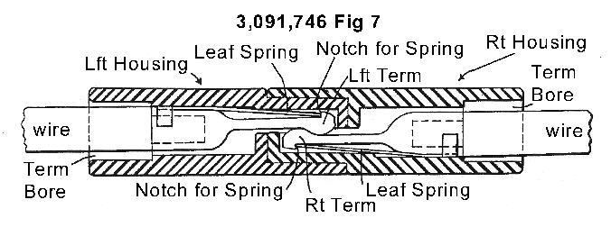
1 Interoperability -- Why Anderson Powerpoles?? Power Poles In the rather frantic and hectic long days and nights of amateur radio emergency operations in the immediate aftermath of the September 2001 World Trade Center attacks; the need for a new and more reliable method of power connectivity arose. The currently used standard Molex power plugs left much to be desired in the continuous operational mode. Their outside plastic covers became fused together from the heat generated over time in use. Enter the Anderson Powerpoles with their reliable and even idiot proof connectivity. There are two main sizes that have become the defacto standard for the ARES amateur community; the 15 amp connector (for use with #16 and #18 gauge wire) and the 30 amp connector (for use with #12 and #14 gauge wire). There are of course the complete range in sizes from 10 Amps up to 180 amps available. The identical connector halves are genderless -- making for ease and quickness of assembly with a minimum number of parts to keep on hand. The molded dovetail design allow you to configure customized assemblies with a wide variety to use in common ARES operations. With a wide range from cigarette lighter connections to automobile battery, solar power, and other power supply types to supply your radios; all connections can be made in a commonality with these small devices. Housings should be mated, viewed from the contact side (opposite the wire side), with the hood up, tongue down, RED on the LEFT, BLACK on the RIGHT. High conductivity silver plated copper contacts give a minimal contact resistance at high current uses. The flat self-wiping contact surface provides for a make and break to keep conducting surfaces clean. Contact detents serve to keep the connectors positively mated in high-vibration applications and give a quick-break, snap action upon disconnect. The non corrosive stainless steel leaf springs will serve to maintain a constant contact pressure and serve in frequent connect/disconnect operations and an intermittent overloading situation. The durable and high impact resistant polycarbonate housings with a UL94 V-O housing material. A 3/32" X 1/4" length roll pin is provided to secure the connectors in the desired configuration; though some desire to use a drop of super glue as a holder. An easy crimp routine for the wire to contact is to face the connector seam toward the concave side of the crimping tool. To remove the contact from the housing use a small blade screw driver or X-Acto blade to lift the front of the contact slightly over the detent in front and gently remove the contact from the rear of the housing. Make up and utilization possibilities are limited only by your imagination. "When all else fails -- Amateur Radio works"
2

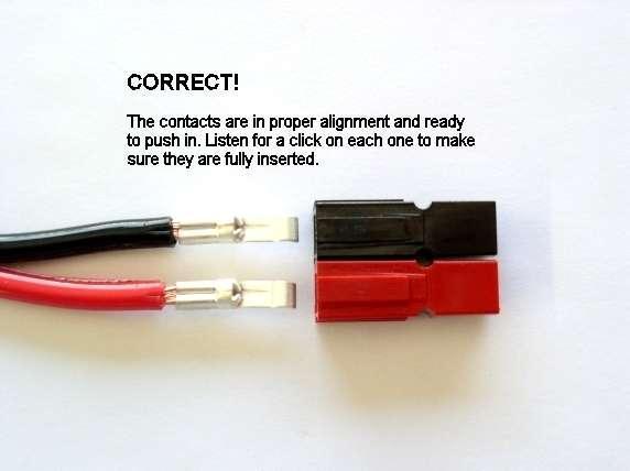
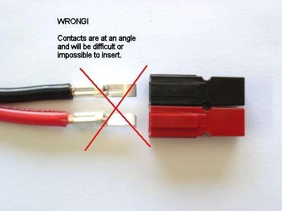
3 The Following is courtesy of Powerpole General Assembly Instructions Assemble the red and black plastic housings together correctly on the first try, they fit snugly and can be difficult to get apart. See the picture below for ARES /RACES standard orientation. Note that you can assemble the red and black insulated housings in other ways for special applications. Put the connector housings together before putting the connector pins in, this is easier, especially when using heavy paired wire. Before soldering or crimping the contacts on to heavy paired wire, orient the contacts so that they are both facing the correct direction so that they go in the housings without twisting the wire. The plastic housings are held together with dovetail joints. Always slide these joints together! They will be damaged if you try to snap them together or apart. They ONLY slide together in one direction. This should be obvious by looking at them carefully. Powerwerx recommends the use of slotted retaining pins. Others do not like the possibility of them falling out in service. If your application is critical and that you want to make the pairing permanent you can use a cyanocrylic glue (Crazy Glue) to hold the connector bodies together. The contacts go in the housings in only one way. Insert the contacts with their sharp edge down against the flat spring that is in the housing. They should slide in and click. If you do not hear a click or they are not fully seated, fix them. When they are inserted fully you should notice that the contact and it's wire "floats" slightly inside it's housing. When looking in from the front of the housing the contact tip should slide over the top of the internal hosing spring. This is the clicking sound that you hear. Be careful when crimping. You may make the contact out of round and it will not slide into the contact easily. This may occur with different types of crimpers and various gauges of wire. To fix this situation you may have to rotate the contact 90 degrees from the original crimping orientation and re-crimp either with the original crimper or a pair of pliers. In any case you need to make the barrel of the contact round again so it can slide in the housing.


4 YOU WILL NOT BE ABLE TO INSERT THE CONTACTS INTO THE HOUSINGS IF THEY ARE TOO WIDE AFTER SOLDERING OR CRIMPING!
5
6
7
8

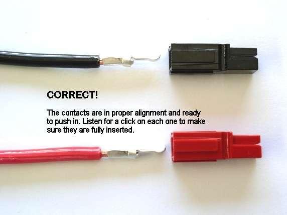
9 Tug slightly on the assembled connector to make sure the contacts are locked in place. If you have trouble getting the contact to lock in to the housing you may have squashed the contact wider deformed it some how. Look at the side profile of the contacts before and after crimping, you may have to bend it back straight before inserting it in to the housing. When soldering the contact pins, be careful not to use too much solder. Keep the solder inside, where the wire goes. If a blob of solder gets on the outside of the connector body you may have trouble putting the contact into the housing. If you get solder on the contact surface area you will not make a good contact. When crimping the contact pins use a crimp that contains the wire completely inside the pin and doesn't spread the connector apart. A good crimp is one where the dimensions of the crimped portion are no more than an un-crimped pin. If the crimp is flattened out you will not be able to easily push the pin in to the body. If you bend the contact blade in relation to the crimp area you should straighten it before putting it in to the body. It is possibly to use larger or smaller gauge wire with the 30 and 45 amp connectors. The 30 amp contacts will work with difficulty with #10 wire if you cut the end cleanly and carefully put each and every strand of that wire in to the pin. It may be is easier to use 45 amp connectors on #10 wire. Using 16 gauge or smaller wire in a 30 amp contact requires that you double or triple up the wire to fill the crimp receptacle of the contact to get a good crimp. A properly crimped contact should have a minimum hold on the wire of more than 25 pounds. A pair of connectors should snap together with 6 to 8 pounds force. Last but not least, MAKE SURE you have the polarity correct before plugging in you equipment. "Measure twice, cut once" as the saying goes.
ANDERSON POWERPOLE CONNECTORS FOR HAM OPERATORS
 ANDERSON POWERPOLE CONNECTORS FOR HAM OPERATORS The Anderson Powerpole connector is a very good connector to sharing connections between users for such things as batteries, radios, chargers and other DC
Golf Trolley Workshop (Devon)
") Golf Trolley Workshop (Devon) Powerpole General Assembly Instructions Assemble the red and black plastic housings together correctly on the first try, they fit snugly and can be difficult to get apart.
Golf Trolley Workshop (Devon) Powerpole General Assembly Instructions Assemble the red and black plastic housings together correctly on the first try, they fit snugly and can be difficult to get apart.
Powerpole General Assembly Instructions
 Powerpole General Assembly Instructions The contacts go in the housings in only one way. Insert the contacts with their sharp edge down against the flat spring that is in the housing. They should slide
POWERPOLE CONNECTORS. Fountain Valley RACES 05 Feb 2008
 POWERPOLE CONNECTORS Fountain Valley RACES 05 Feb 2008 ACCESORIES SPLITTER WITH OEM T-CONNECTOR ACCESSORIES RED DEE 2 SPLITTER Any connection point is an input / any connection point is an outlet ACCESSORIES
Anderson Powerpoles. Powerpole Assembly. (PowerWerx Insructions)
") Anderson Powerpoles Powerpole Assembly (PowerWerx Insructions) Seaching for a Standard The old standard Molex 2-pin connectors could no longer hold up to the amp requirements of mobile and portable equipment
Anderson Powerpoles Powerpole Assembly (PowerWerx Insructions) Seaching for a Standard The old standard Molex 2-pin connectors could no longer hold up to the amp requirements of mobile and portable equipment
ARES PRESENTATION Anderson Powerpoles
 ARES PRESENTATION Anderson Powerpoles Steve Pituch EC, February 13, 2010 There is a very good reason for all ARES members to use Anderson Powerpoles on all their 12 Volt equipment including all radios,
W7MRI's Anderson Powerpole. Power Hub
 W7MRI's Anderson Powerpole Power Hub This PDF is provided by K7JM at http://radio.mcdougallshome.net Don, W7MRI made up a nice small circuit board that holds 7 pairs of Anderson Powerpole connectors to
Repairing your Porsche 928 Central Warning System (CWS) controller
 controller") Repairing your Porsche 928 Central Warning System (CWS) controller Disclaimer: This procedure is for a 1984 Porsche 928 S controller. Overview: Under the left foot pedal (dead pedal) of the Porsche 928
Repairing your Porsche 928 Central Warning System (CWS) controller Disclaimer: This procedure is for a 1984 Porsche 928 S controller. Overview: Under the left foot pedal (dead pedal) of the Porsche 928
Assembly Instructions: Kit #5
 Assembly Instructions: Kit #5 1. Insert the T-pin into one of the caps. 2. Insert the rotor core into the same cap as shown below. Apply some pressure to push the rotor core approximately 1/2" (10-12 mm)
STRENGTH Aligned teeth provide superior gripping power over standard vertical teeth. STRENGTH Diamond serrated jaws provide a firm grip
 STRENGTH Aligned teeth provide superior gripping power over standard vertical teeth STRENGTH Diamond serrated jaws provide a firm grip PLIERS AND SNIPS Locking Pliers Slip Joint Pliers Electrician s Pliers
Harmony Remote Repair
 Harmony Remote Repair harmonyremoterepair.com How to install your new Harmony One Front Cover/Touch Screen Important! Before you begin working on your Harmony One, you must discharge any static electricity
The wick in your heater needs replacing if, after repeated cleanings, any of the following conditions still exist:
 WICK REPLACEMENT The wick in your heater needs replacing if, after repeated cleanings, any of the following conditions still exist: Slow to light, hard movement of the wick adjuster knob, kerosene odor
Repairing Microsoft Wedge Touch Mouse Battery Cover Retaining Clip
 Repairing Microsoft Wedge Touch Mouse Battery Cover Retaining Clip Disassembly, repair and reassembly of Wedge Touch mouse when the battery cover will not stay closed. Also is a good guide to repair other
Powerpole Connectors - PP75: up to 120 Amps
 Powerpole Connectors - PP75: up to 120 Amps PP75 with Mounting Wings PP75 series Powerpole housings can be used for wire-to-wire, wire-to-board, and wire-to-busbar applications. Wire sizes from #16 AWG
SBE 160 / SBX 175 ORDERING INFORMATION SECTION 3. Touch Safe Interface Minimizes potential contact with live circuits per IEC & IEC 60529
 Connectors - up to 175 Amps SBX and SBE connectors can integrate up to 8 auxiliary power / signal contacts along with the two primary power circuits. SBE connectors feature an IEC 60950 touch safe housing
Powerpole Connectors - PP75: up to 120 Amps
 Powerpole Connectors - PP75: up to 120 Amps PP75 with Mounting Wings PP75 series Powerpole housings can be used for wire-to-wire, wire-to-board, and wire-to-busbar applications. Wire sizes from #16 AWG
Powerpole Connectors - PP75: up to 120 Amps
 Powerpole Connectors - PP75: up to 120 Amps PP75 with Mounting Wings PP75 series Powerpole housings can be used for wire-to-wire, wire-to-board, and wire-to-busbar applications. Wire sizes from #16 AWG
SBE 320 / SBX 350 Connectors - up to 350 Amps
 Connectors - up to 350 Amps ORDERING INFORMATION SBX and SBE connectors can integrate up to 8 auxiliary power / signal contacts along with the two primary power circuits. Sequencing within auxiliary positions
MX150L tm INDUSTRIAL SEALED CONNECTOR SYSTEM
 MX150L tm INDUSTRIAL SEALED CONNECTOR SYSTEM The MX150L Industrial Sealed Connector System is IP67 rated and conforms to UL 1977, but it is NOT suitable for automotive applications with requirements such
Application Tooling Specification Sheet
 Extractor Tool FEATURES Application Tooling Specification Sheet Order No. 63813-2700 This Extractor Tool is for the removal of Wire-to-Wire and Wire-to-Board terminal series in both plug and receptacles.
1104. Clean up the door striker plates with a hand grinder using a wire brush and WD-40.
 Chapter 31 - Misc. Putting VW Back Together (Video Clip 31) 1104. Clean up the door striker plates with a hand grinder using a wire brush and WD-40. 1105. Install both door striker plates on the VW body
Application Tooling Specification Sheet
 Modular Crimp Head Order No. 63811-5970 FEATURES Application Tooling Specification Sheet TYPE 4A Hand Crimp Tool Order No. 63811-5900 % A full cycle ratcheting hand tool ensures complete crimps % Ergonomically
HARTING Han GND. People Power Partnership
 98 42 937 0201 HARTING Han GND People Power Partnership Han GND - Mateable Potential Equalization The new Han GND series now enables pluggable grounding systems Han GND (Han Ground) is the innovative HARTING
Removing and Replacing the Y-truck
 Service Documentation Removing and Replacing the Y-truck To remove and replace the Y-truck you will need the following tools: 4mm Allen wrench 12mm stamped flat wrench #2 Phillips screwdriver (magnetic
BrewsBySmith.com STC DIY Kit
 BrewsBySmith.com STC-1000 + DIY Kit Contact Information: Greg Smith www.brewsbysmith.com greg@boostbysmith.com I. Hardware Included: STC-1000 flashed with latest software (v1.06 currently) (if purchased)
1. Turn off or disconnect power to unit (machine). 2. Push IN the release bar on the quick change base plate. Locking latch will pivot downward.
. 2. Push IN the release bar on the quick change base plate. Locking latch will pivot downward.") Figure 1 Miniature Quick Change Applicators, of the end feed type, are designed to crimp end feed strip terminals to prestripped wires. Each applicator is set up to accept the strip form of certain specific
Figure 1 Miniature Quick Change Applicators, of the end feed type, are designed to crimp end feed strip terminals to prestripped wires. Each applicator is set up to accept the strip form of certain specific
[ 21.3 ] 0.84 A [ 13.0 ] 0.51
![[ 21.3 ] 0.84 A [ 13.0 ] 0.51](/thumbs/92/108061905.jpg "[ 21.3 ] 0.84 A [ 13.0 ] 0.51") Connectors - up to 175 Amps SBX and SBE connectors can integrate up to 8 auxiliary power / signal contacts along with the two primary power circuits. SBE connectors feature an IEC 60950 touch safe housing
Connectors - up to 175 Amps SBX and SBE connectors can integrate up to 8 auxiliary power / signal contacts along with the two primary power circuits. SBE connectors feature an IEC 60950 touch safe housing
Stac64 Unsealed Connector System
 Unsealed Connector System 2.54mm (.100") Pitch 34729 Female 22.70 x 22.23 Features and Benefits Pre-assembled TPA to receptacle housing shipped as single assembly provide applied labor and cost savings
DO NOT PULL ON THE SHEATH.
 Removing and Replacing the Head Cover To remove and replace the head cover you will need the following tools: #2 Phillips screwdriver (magnetic tip preferred) Removing the Head Cover 1. Ready the machine
Powerpole Connectors - PP120: up to 240 Amps
 Powerpole Connectors - : up to 240 Amps series Powerpole housings are designed to accommodate up to 1/0 ( mm²) wires and handle high currents up to 240 amps. Reducing bushings allow to accept down to #8
1503 Follow Spot Yoke, Source Four LED
 1503 Follow Spot Yoke, Source Four LED Rev 1.0 2016 City Theatrical, Inc. Getting Started with the City Theatrical Follow Spot Yoke for source four LED Congratulations on the purchase of your City Theatrical
unit 3: GENErAL ElectriCAL SySTEM DiAGNOSiS
 Electrical/Electronic Systems unit 3: GENErAL ElectriCAL SySTEM DiAGNOSiS lesson 4: wire and connector repairs I. Connector repairs A. Connector repairs involve fixing damaged wires. Wires are marred due
RH-412 STEEL DOORS INSTALLATION INSTRUCTIONS
 RH-412 STEEL DOORS INSTALLATION INSTRUCTIONS By following the steps outlined below, the assembly, installation and adjustment of the steel doors, will be a simple process. Let s start with the Driver Side.
onlinecomponents.com
 Figure 1 PRO CRIMPER III Hand Crimping Tool Assembly 58603 1 consists of Die Assembly 58603 2 and PRO CRIMPER III Hand Tool Frame 354940 1. The die assembly consists of crimping dies and a locator assembly.
Line-Following Robot
 1 Line-Following Robot Printed Circuit Board Assembly Jeffrey La Favre October 5, 2014 After you have learned to solder, you are ready to start the assembly of your robot. The assembly will be divided
HE Insert Series. Application Specification Apr 26 th, 2016 Rev. A. Table of contents
 HE Insert Series Table of contents 1. INTRODUCTION... 2 2. SUPPORTING DOCUMENTS... 2 2.1. Customer drawings... 2 2.2. Product specification... 2 2.3. Application Specification... 2 2.4. Standards... 2
Read these instructions thoroughly before crimping any contacts.
 PRO CRIMPER III Hand Crimping Tool Assembly 58583 1 consists of Die Assembly 58583 2 and PRO CRIMPER III Hand Crimping Tool Frame 354940 1. The die assembly consists of crimping dies and a locator assembly.
Application Tooling Specification Sheet
 Hand Crimp Tool Application Tooling Specification Sheet TYPE 4D Order No. 63819-1300 FEATURES A full cycle ratcheting hand tool ensures complete crimps Ergonomic soft grip handles for comfortable crimping
Hatchback Wing Riser Kit
 Hatchback Wing Riser Kit 2015-06-11 Thank you for purchasing this PERRIN product for your car! Installation of this product should only be performed by persons experienced with installation of aftermarket
SBS Connectors - up to 110 amps
 Connectors - up to 1 amps NEW 75G 75X Wire to Wire The patented connector family is designed to provide high power in a compact ergonomic housing with protection against accidental contact with live circuits.
S T E P 1. Tools Needed. Curved Needle Nose Pliers. L Shaped Tool (Supplied w/ kit) Flathead Eyeglasses Screwdriver
 Flathead Eyeglasses Screwdriver") Curved Needle Nose Pliers Flathead Eyeglasses Screwdriver L Shaped Tool (Supplied w/ kit) Tools Needed 2 Make sure weapon is pointed in a safe direction, unloaded, and on safe. 3 Remove lower receiver
Curved Needle Nose Pliers Flathead Eyeglasses Screwdriver L Shaped Tool (Supplied w/ kit) Tools Needed 2 Make sure weapon is pointed in a safe direction, unloaded, and on safe. 3 Remove lower receiver
SB 50 Connectors - up to 120 amps
 Connectors - up to 120 amps Based off the design pioneered by Anderson in 1953, APP s two pole SB connectors set the standard for DC power distribution and battery connections. connectors feature a one
Section 5 BATTERY REPLACEMENT
 u Section 5 BATTERY REPLACEMENT j i 5.1 General The internal battery is used for preserving the clock and programming memory in the models 5000 and 7000. I i The procedure for each is given separately.
Pliers. Pliers PLIERS
 Pliers Pliers PILERS Long Nose Pliers With Side Cutter Comfortable two-component handles combine durability with a secure non-slip grip. High-leverage joint placement increases leverage to reduce the cutting
Application Tooling Specification Sheet
 HAND CRIMP TOOL FEATURES Application Tooling Specification Sheet TYPE 4D Order No. 63827-1400 A full cycle ratcheting hand tool ensures complete crimps Ergonomic soft grip handles for comfortable crimping
Application Tooling Specification
 Order No. 63828-2000 Application Tooling Specification Type 4G FEATURES A full cycle ratcheting hand tool ensures complete crimps Ergonomically designed soft handles Precisely designed crimping profiles
Terminal Replacement Procedures
 HOW TO REPLACE CONNECTOR TERMINALS The terminal repair kits provide necessary tools and materials (terminals, wire seals, and splice connectors) to repair many damaged or faulty connector terminals. However,
SBE 80 / SBO 60 Connectors - up to 80 Amps
 Connectors - up to 80 Amps SBE and SBO connectors build on the capability of the two pole SB connectors by offering up to 8 auxiliary power / signal contacts along with an IEC 60950 touch safe housing.
Signal Mirror Installation Instructions
 Signal Mirror Installation Instructions 2005-2010 Chevy Corvette C6 THE safety accessory of the 21 st Century. P/N 210-0144-0 Rev. A3 (9/29/2011), BTV 2007 Muth Mirror Systems, LLC Page 3 of 10PplPage
Application Tooling Specification Sheet
 Modular Crimp Head Order No. 63819-4670 FEATURES Application Tooling Specification Sheet TYPE 4A Hand Crimp Tool Order No. 63819-4600 % A full cycle ratcheting hand tool ensures complete crimps % Ergonomically
INSTALLATION INSTRUCTIONS RH 412 STEEL DOORS
 By following the steps outlined below, the assembly, installation and adjustment of the steel doors, will be a simple process. Let s start with the Driver Side. Note: Having the hood open makes the job
Jewelry Basics 101. Basic Wire Loops For best results, use both chain-nose and round-nose pliers. Method 2 Bend then cut. Method 1 Cut then bend
 Jewelry Basics 101 #68-007-01 Basic Wire Loops For best results, use both chain-nose and round-nose pliers. Method 2 Bend then cut Use non-serrated chain-nose pliers to bend the wire just above the bead.
Professional Pliers. Quality to Depend on
 Professional Pliers Quality to Depend on - 227 - High Leverage Pliers High Leverage Pliers High Leverage pliers boast a labor-saving design to generate greater productivity with less effort. Ergonomic
SBS Connectors - up to 110 amps
 SBS Connectors - up to 11 amps SBS 75G SBS 75X Wire to Wire The patented SBS connector family is designed to provide high power in a compact ergonomic housing with protection against accidental contact
Installation Instructions Road King Classic Saddlebag Bezels
 Installation Instructions Road King Classic Saddlebag Bezels Thank you for your purchase of Bagger Audio Road King Classic Saddlebag Bezels for your Harley-Davidson motorcycle. We have carefully engineered
Series 1500 Aluminum Door Canopy
 Series 500 Aluminum Door Canopy with Sidewings It is our recommendation that you read instructions carefully prior to assembly and installation. Series 500 with Sidewings mounting bar (A) top trim (B)
EmagiKit. Privacy Pod Plus. Quiet. Easy. Affordable. INSTRUCTIONS ASSEMBLY
 EmagiKit Privacy Pod Plus Quiet. Easy. Affordable. INSTRUCTIONS ASSEMBLY DIMENSIONS AND COMPONENTS 47 47 Ceiling Unit 2-B 2-L 2-R Glass Door Corner Trim Door Handle 90 Adjustable Height Work Surface 1-B
LUX INSTALLATION GUIDE. LUX Panel V Groove Installation. Installation Guide. February
 LUX Panel V Groove Installation Installation Guide February 2017 www.luxpanel.ca LUX Panel V Groove Installation LUX panel steel cladding is designed to be installed vertically, horizontally, diagonally
Assembly Instructions for Power Drawer Series 35 amp and 75 amp
 Assembly Instructions for Power Drawer Series 35 amp and 75 amp These assembly instructions include the instructions for wire termination, contact insertion, contact removal, PCB mount, and panel mounting
7878 K940. Checkpoint Antenna. Kit Instructions. Issue B
 7878 K940 Checkpoint Antenna Kit Instructions Issue B Revision Record Issue Date Remarks A July 7, 2009 First issue B Nov2013 Revised the Checkpoint installation procedures for 7878 and 7874 scanners Added
Series 1100 Aluminum Door Canopy
 Series 00 Aluminum Door Canopy with Support Arms It is our recommendation that you read instructions carefully prior to assembly and installation. Series 00 with Support Arms MOUNTING BAR (A) TOP TRIM
A socket contact support (supplied separately) must be installed onto the locator assembly.
 must be installed onto the locator assembly.") Figure 1 PRO CRIMPER III Hand Tool Assembly 1976444 1 consists of PRO CRIMPER III Hand Tool Frame 354940 1 and Die Assembly 1976444 2. The tool assembly is used to crimp the contacts listed in Figure 1.
Figure 1 PRO CRIMPER III Hand Tool Assembly 1976444 1 consists of PRO CRIMPER III Hand Tool Frame 354940 1 and Die Assembly 1976444 2. The tool assembly is used to crimp the contacts listed in Figure 1.
Application Tooling Specification
 Order No. 63828-1200 Application Tooling Specification Type 4D FEATURES A full cycle ratcheting hand tool ensures complete crimps Ergonomic soft grip handles for comfortable crimping A precision, user-friendly
Signal Mirror Installation Instructions Toyota Tacoma
 Signal Mirror Installation Instructions 2005-2015 Toyota Tacoma THE safety accessory of the 21 st Century. P/N 210-0115-0 Rev. A4 (3/11/15), BTV 2005 Muth Mirror Systems, LLC Page 3 of 12PplPage 3 of 12
Application Tooling Specification Sheet
 HAND CRIMP TOOL Application Tooling Specification Sheet TYPE 4D Order No. 63828-0200 FEATURES A full cycle ratcheting hand tool ensures complete crimps Ergonomic soft grip handles for comfortable crimping
Order Number
 Order Number 200218-5500 FEATURES Application Tooling Specification TYPE 4D A full-cycle ratcheting hand tool ensures complete crimps Ergonomic soft grip handles for comfortable crimping A precision user-friendly
Installation Guide. Bi-fold Doors
 Installation Guide Bi-fold Doors Installation Guide Components box 1. 6. 2. 3. 7. 5. 4. 8. Contents 1. Fixing plugs 2. Wedge gasket 3. Bottom trolley 4. Top trolley 5. Magnetic keep (x 2 if door height
Hand Crimp Tool Operating Instruction Sheet And Specifications Part No Eng. No. RHT 1752 (Replaces )
") FEATURES Hand Crimp Tool Operating Instruction Sheet And Specifications Part No. 64003-1200 Eng. No. RHT 1752 (Replaces 19284-0011) ΠΠΠA full cycle ratcheting hand tool ensures complete crimps Long
FEATURES Hand Crimp Tool Operating Instruction Sheet And Specifications Part No. 64003-1200 Eng. No. RHT 1752 (Replaces 19284-0011) ΠΠΠA full cycle ratcheting hand tool ensures complete crimps Long
Chicago Electric MIG B Gun Install
 Chicago Electric MIG 180 81295B Gun Install Step 1 First you will need to remove all the side panels on your machine. This is necessary to access everything for this install. Step 2 On the side with your
Application Tooling Specification Sheet
 HAND CRIMP TOOL FEATURES Application Tooling Specification Sheet TYPE 4D Order No. 200218-2400 A full cycle ratcheting hand tool ensures complete crimps Ergonomic soft grip handles for comfortable crimping
Application Tooling Specification Sheet
 HAND CRIMP TOOL Application Tooling Specification Sheet TYPE 4D Order No. 63827-7500 FEATURES A full cycle ratcheting hand tool ensures complete crimps Ergonomic soft grip handles for comfortable crimping
Product #: Product #:
 STANLEY FATMAX Push-Lock Groove Joint Pliers Multi-purpose jaws designed to grasp flat and round objects. Push-Lock technology allows for quick and easy adjustment in 17 positions. Induction hardened jaws
METRI-PACK 2016 FEATURE PRODUCT JUL. Sealed Connector Systems OF THE MONTH. Weather-Pack And Deutsch Connector. tifcoonline.
 JUL METRI-PACK 2016 Weather-Pack And Deutsch Sealed Systems FEATURE PRODUCT OF THE MONTH www.tifco.com tifcoonline.com Phone: 800.868.4326 Fax: 800.535.4619 tifco@tifco.com Main Office: Houston, TX Branch
Order Number
 Order Number 200218-5900 FEATURES Application Tooling Specification TYPE 4D A full-cycle ratcheting hand tool ensures complete crimps Ergonomic soft grip handles for comfortable crimping A precision user-friendly
Ribcage Installation. Part 2 - Assembly. Back-Bone V1.06
 Ribcage Installation Part 2 - Assembly Back-Bone V1.06 Contents Section 1 Before You Get Started... 2 Included With Your Kit:... 2 Figure: A... 3 CAUTION!... 4 Note:... 4 Tools Required... 5 Section 2:
Bi-Color Signal Mirror Installation Instructions
 Bi-Color Signal Mirror Installation Instructions 2005-2009 Toyota Tacoma THE safety accessory of the 21 st Century. P/N 210-0141-0 Rev. A2 (3/30/09), BTV 2007 Muth Mirror Systems, LLC Page 3 of 13PplPage
MAG-MATE* Series 300 Terminals
 MAG-MATE* Series 300 Terminals Application Specification 114-2046 28 NOV 18 Rev AB All numerical values are in metric units [with U.S. customary units in brackets]. Dimensions are in millimeters [and inches].
Assembly Procedures for 96-Position GPEC II and III Sealed Connector System (Harness)
") Assembly Procedures for 96-Position GPEC II and III Sealed Connector System (Harness) Instruction Sheet 408-10229 08 SEP 17 Rev E Wire Dress Assembly (Straight Version) Plug Housing Assembly Optional Blink
Assembly Procedures for 96-Position GPEC II and III Sealed Connector System (Harness) Instruction Sheet 408-10229 08 SEP 17 Rev E Wire Dress Assembly (Straight Version) Plug Housing Assembly Optional Blink
SAVVY OFF ROAD GAS TANK SKID INSTALLATION INSTRUCTIONS
 It is best to work with a fuel tank that has the least amount of fuel in it as possible. Thank you for purchasing the best skid on the market. Please follow these instructions and your installation should
Pow-R-Feed Systems Service Manual
 Pow-R-Feed Systems Service Manual Important Safety Instructions Please read this manual carefully and follow its instructions. Improper use or failure to follow these instructions could result in serious
Application Tooling Specification Sheet
 HAND CRIMP TOOL FEATURES Application Tooling Specification Sheet TYPE 4D Order No. 200218-1700 A full-cycle ratcheting hand tool ensures complete crimps Ergonomic soft grip handles for comfortable crimping
AMPSEAL* Automotive Plug Connector and Header Assembly
 AMPSEAL* Automotive Plug Connector and Header Assembly Application Specification 114-16016 17 APR 14 NOTE NOTE i All numerical values are in metric units [with U.S. customary units in brackets]. Unless
Catch The Bug. Body Build. Where are we? Process # You are. here.
 Catch The Bug Body Build Process # 1 Where are we? 1) Body Build- The mechanical part of the bug is constructed. 2) Electronics Lab- Bug Experiments teach the fundementals of electronics. 3) Final Wiring-
REP Design LLC. 193 Winding Ridge Rd, Southington, CT INSTALLATION INSTRUCTIONS:
 REP Design LLC 193 Winding Ridge Rd, Southington, CT 06489 1-860.426.1894 n7emw@cox.net www.repdesign.us INSTALLATION INSTRUCTIONS: SHD-SO239 Super Heavy Duty SO-239Antenna Mounting System Thank you for
Miniature Circular Plastic Connector (CPC)
") Miniature Circular Plastic Connector (CPC) Application Specification 16 SEP 03 Rev O All numerical values are in metric units [with U.S. customary units in brackets]. Dimensions are in millimeters [and
Miniature Circular Plastic Connector (CPC) Application Specification 16 SEP 03 Rev O All numerical values are in metric units [with U.S. customary units in brackets]. Dimensions are in millimeters [and
Handling Precaution for Terminal and Connector
 1 Handling Precaution for Terminal and Connector Handling Precaution for Terminal and Connector This manual is to describe basic precautions for use of terminal and connector in the following. Make use
TNC SERIES General... 4 Interface... 5 Characteristics...6-7
 CONTENTS PAGE TNC SERIES General... 4 Interface... 5 Characteristics...6-7 TNC 50 Ω SERIES Plugs...8-9 Jacks...0- Jacks and receptacles... Receptacles...-4 Adapters... 5 Caps... 6 TNC 75 Ω SERIES Plugs...
Application Tooling Specification Sheet
 HAND CRIMP TOOL Application Tooling Specification Sheet TYPE 4D Order No. 63827-1500 FEATURES A full cycle ratcheting hand tool ensures complete crimps Ergonomic soft grip handles for comfortable crimping
AR-15 Lower Receiver Assembly Instructions
 AR-15 Lower Receiver Assembly Instructions Tools There are a few tools that make it easier to put together these kits, but none of them are necessary. Minimum requirements include a hammer and punch to
BIG CEE. ENGINEERING 627 N Michigan Ave #5 Pasadena, CA
 Garmin Emap power adapter housing BIG CEE ENGINEERING 627 N Michigan Ave #5 Pasadena, CA 91106 bigcee@bigcee.com www.bigcee.com This kit allows you to remove the circuit board from your Emap 12V adapter
Lima XPT/HST Re-Powering Conversion
 Lima XPT/HST Re-Powering Conversion Please read through these instructions before beginning the conversion process. Non-Powered Bogie The front non-powered bogie is the starting point for this conversion.
Instructions to fit Emulator in place of floppy drive M.D.R.
 Instructions to fit Emulator in place of floppy drive M.D.R. Before starting, read through all the following instructions, and then when you do begin, read each number section before attempting that particular
Sentinel Series Cigar Humidor End Tables
 Sentinel Series Cigar Humidor End Tables Assembly Instructions Models: Sentinel 500, 1000 and 1500 Style: Contemporary SENTINEL ASSEMBLY INSTRUCTIONS Congratulations! You have purchased a superior cigar
FABA. Installation Instructions. Conductor Bar System. Publication #FABA-03 3/1/04 Part Number: Copyright 2004 Electromotive Systems
 FABA Conductor Bar System Installation Instructions Publication #FABA-03 3/1/04 Part Number: 005-1062 Copyright 2004 Electromotive Systems 1S 100 Z Installation Instructions Contents: Basic Diagram - -
Application Tooling Specification Sheet
 HAND CRIMP TOOL Application Tooling Specification Sheet TYPE 4D Order No. 63825-8200 FEATURES A full cycle ratcheting hand tool ensures complete crimps Ergonomic soft grip handles for comfortable crimping
Instructions for Lighting an S Scale Caboose
 Instructions for Lighting an S Scale Caboose The S Scale Caboose lighting kit is adaptable for most caboose models of rolling stock including American Flyer (TM) and contains the same components as found
Application Tooling Specification
 Order No. 200218-2200 Application Tooling Specification Type 4D FEATURES A full cycle ratcheting hand tool ensures complete crimps Ergonomic soft grip handles for comfortable crimping A precision, user-friendly
Written By: Adam O'Camb
 iphone XR Display Assembly Replacement Replace a cracked or faulty LCD screen in your iphone XR. Written By: Adam O'Camb ifixit CC BY-NC-SA www.ifixit.com Page 1 of 23 INTRODUCTION If your iphone XR screen
AR-15 Armorer s Essentials Kit. Product # Instructions # Revision: B
 AR-15 Armorer s Essentials Kit Product #156111 Instructions #1025769 Revision: B 1 INDEX 3 AR-15 Adjustable Receiver Link 3 Pivot Pin and Roll Pin Installation Tool 4 Mag well Vise Block 7 Upper Vise Block
MIL-STD B (SH) UPDATE
 UPDATE") MIL-STD-2042-5B (SH) UPDATE Method 5A1 Insert Equipment and materials (to be added to table 5A1-I) Pliers 3.2.2.2 Cable and fiber preparation for Fiber Systems International backshells. Step 1: Ensure
MIL-STD-2042-5B (SH) UPDATE Method 5A1 Insert Equipment and materials (to be added to table 5A1-I) Pliers 3.2.2.2 Cable and fiber preparation for Fiber Systems International backshells. Step 1: Ensure