Anderson Powerpoles. Powerpole Assembly. (PowerWerx Insructions)
|
|
|
- Jocelyn Lawrence
- 5 years ago
- Views:
Transcription
1 Anderson Powerpoles Powerpole Assembly (PowerWerx Insructions)

2 Seaching for a Standard The old standard Molex 2-pin connectors could no longer hold up to the amp requirements of mobile and portable equipment so a reliable replacement was needed as specified below: 1. To handle 30/45 amps continuous load 2. To mate and un-mate quickly and easily 3. To maintain a reliable connection via friction 4. To grip wire securely without exposure to the power conductors 5. To be assembled with a standard crimping tool (TRIcrimp) 6. To have silver-plated copper contacts for corrosion resistance 7. To have self-wiping design provides good electrical contact 8. To be small, lightweight, color-coded 9. To be genderless connector works for both ends of conductor 10. To be stacked for multiple connections with single insertion 11. To allow 100,000 no-load insertions 12. To allow 250 full-load hot plugs
3 1999 OES BULLETIN EMC204 DC Connectors Standard To: Emergency Communications Units - Information Bulletin To: Emergency Management Agencies via Internet and Radio By: Auxiliary Communications Service (ACS) of the California Governor's Office of Emergency Services EMC204 DC Connectors Standard For release October 4, l999 Following the bulletins on Battery Power we were asked more about the cable connectors adopted for our ACS unit. We recognize there are a variety of opinions, so this is what we've learned and decided. Whatever connector you use we recommend that you have several of them made up with the other end unconnected, but stripped bare ready to connect. That way you will have the clear opportunity to match whatever needs may unexpectedly occur. At State OES ACS we use the Anderson Powerpole for our standard use. We do recommend them for use by County and City ACS, RACES and ARES personnel in California so there will be fewer problems when units are working under mutual aid in support of each other. Obviously it is not mandatory. For those who use a different connector we urge you acquire some Anderson Powerpole connectors and make up a few "jumper" cables to interconnect between yours and the Andersons (or vice versa). That's prudent planning and reduces the stress when in a tight situation. It helps to show others that you are professionally prepared for the unexpected.
4 1999 OES BULLETIN (CONTIN.) For our purposes we use 15 or 30 ampere sizes; however, Anderson lists sizes of 10, 15, 30, 45, 75, 120 and 180 amperes. The connectors come in Red and Black. Due to the way they are mated they are genderless, in that the mating process can be altered to those cases where someone wants red (positive) on the right and black (negative) on the left instead of the other way (Red on left, Black on right) when viewing from the contact end. Most users find them easy to assemble, change and dissemble. They are cleverly designed. Until you use and assemble one it's difficult to appreciate how - and why - they work so well. They can be connected to the wire by either solder or crimp. Personally, I prefer solder. Just be frugal with it to avoid oversizing the pin that will be inserted into the rear of the connector. A small blade screwdriver can be used to assist the insert process when placing the wired terminal into the plastic connector halves. Thanks for your input to these bulletins. It's always a help. Cary Mangum, W6WWW, State ACS Officer, State OES, CA cary.mangum@macnexus.org or cary_mangum@oes.ca.gov ---
5 Why Use Powerpoles? 1. Declared the Standard 12 VDC emergency connector for ARES/RACES, County, City and State OES/ACS use by a 1999 bulletin from Governor s Office of OES. 2. They are proven, reliable, high-amperage connectors for all types of accessory equipment: radio, automotive, solar, USB, linear amps, etc. 3. Allow interchangeability of DC power between groups 4. Standard polarity colors: RED positive; BLACK negative 5. Correct polarity is maintained at either end of the genderless connections 6. Connectors can adapt to a variety of wire gauges 7. Can be stacked together vertically or horizontally to allow multiple connections with a single plug insertion 8. Universally available through internet and retail stores
6 Powerpole Identification PP15/30/45 ALL PP15/30/45 are interchangeable with different barrel sizes. MOST POPULAR for Ham Radio


7 Powerpole elements Fingerproof Rib 2. Housings Contacts 3 4. Lock pins 4

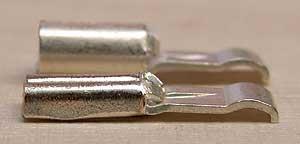
8 15/30- Only difference is the size of the wire barrel on contact 45A-Style of wire mount is different than the 15/30 When connected, hard to distinguish other than wire gauge used. PP 15/30/45 Different Barrel Sizes Available 45A 30A 15A


9 One housing design, THREE contact options


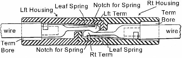
10 Anatomy of a Powerpole
11 Powerpole assembly tools Three basic tools needed 1. Wire cutters 2. Wire strippers 3. Contact crimper *

12 Wire cutters Nothing fancy. Good and sharp Appropriate to gauge of wire your using.

13 Wire Strippers Good and sharp Appropriate to gauge of wire your using.
14 Contact Crimper Crimping is the heart of the procedure! Mess this up and you ve botched the whole thing (the contact won t insert or the wire could pull out.) Three different styles of crimpers: 1. Not-Recommended style 2. If-you-have-money-to-burn style 3. Just-right style

15 Not-Recommended Style Guaranteed to mess up-do NOT USE. Inconsistent results Inexpensive $12.99 Overall rating, 0

16 If-you-have-money-to-burn style Consistent results! Official APP crimper Only does 30 and 45A contacts $219.99! Anderson Power Pole Crimpers

17 Just-Right Style TRIcrimp, Powerpole Crimping Tool Consistent results Does 15A, 30A & 45A contacts! $39.95!
18 Assembly procedures
19 HOUSING SELECTION RED + 12 VDC BLACK 12 VDC
20 Correct ORIENTATION OF HOUSINGS Housing orientation is VERY important! Looking at FRONT of the housing: 1. Have the fingerproof ribs UP 2. RED on LEFT 3. BLACK on RIGHT Housing Assembly NOTE: These are the instructions that PowerWerx gives in their assembly guide on their web site.

21 Locking pins... THROW THEM AWAY OR RECYCLE! Can vibrate apart Steel and electricity not good partners. Just glue it! Locking Pins?
22 CONTACT ASSEMBLY 1. Square off the wire ends 2. Separate conductors about 1/2 inch+ 3. Strip conductors back approximately 5/16 inch 4. If stranded wire, twist the bundle to avoid whiskers 5. DO NOT TIN the wire ends with solder 6. Insert conductor into contact barrel. The insulation should be almost flush and bare wire barely seen out the back of the contact. Trim if needed.

23 CONTACT ASSEMBLY(continued) 9. Insert contact curve down into crimper. 10. Squeeze one or two clicks to hold contact 11. Re-insert wire if necessary to align 12. FIRMLY SQUEEZE handle all the way thru the cycle and release. 13. Conductor done! 14. Note: For the 45A contact: You may need to squeeze the wire crimp wings just a bit to get it to a U shape to fit into the crimper.


24 Powerpole Contact Assembly Procedure The best crimping tool for the money is the TRIcrimp, Powerpole Crimping Tool for 15, 30 and 45 amp contacts

25 Incorrect Crimping Technique NO Regardless of the crimping tool used, the seam in the barrel of the contact must be against the rounded side of the tool s die.

26 Crimp Should look just like this! NOTE: Insulation is flush with contact and very little bare wire is exposed.

27 This is also the correct orientation for insertion into the correctly color coded housing!

28 INCORRECT example Contact blades bent. Gently straighten them up.


29 CORRECT examples Contact straight Contact correctly aligned Contact correctly polarized Ready to insert
30 Final connector assembly Insert contact curve down towards the tongue ("A") of the housing Slide straight in until CLICK is heard or felt. (A small screwdriver may help insertion.) Tug back on conductor to verify lock DONE! One powerpole completed! Repeat with other conductor.

31 Cutaway showing contact locked into connector
32 OOPS! I goofed up! I need to remove the contact from the housing. Contact Removal A special APP tool is available to help remove the contact from the housing. BUT, 3MM flat blade screwdriver will also do the same thing and is much cheaper.
33 Contact Removal Pry this spring up! Pull on conductor to remove!
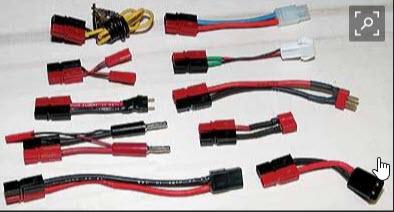
34 COMMON 15/30/45 POWERPOLE APPLICATIONS

35 Eye Terminal Battery Connection with fuses

36 Fused Battery Clip

37 ONE -TO- MANY Outlets
38 OEM RADIO CONNECTIONS

39 Popular YAESU T CONNECTOR


40 LOCKING THE HOUSINGS D I Y
41 After Thoughts. The 15/30/45 Powerpole a good choice for ham radio but try a bit larger wire size such as GA The housings mate together side-by-side through molded dovetails. Buy more contacts than you will need for your project crimping takes some skill. Keep your housings, contacts, wire, and crimping tool in your "GO kit." This way, you can make field repairs or even construct new cables on the spot.
42 WHERE TO BUY STUFF Vendors include: =HRO
Power Poles. Interoperability -- Why Anderson Powerpoles??
 Interoperability -- Why Anderson Powerpoles?? Power Poles In the rather frantic and hectic long days and nights of amateur radio emergency operations in the immediate aftermath of the September 2001 World
POWERPOLE CONNECTORS. Fountain Valley RACES 05 Feb 2008
 POWERPOLE CONNECTORS Fountain Valley RACES 05 Feb 2008 ACCESORIES SPLITTER WITH OEM T-CONNECTOR ACCESSORIES RED DEE 2 SPLITTER Any connection point is an input / any connection point is an outlet ACCESSORIES
ANDERSON POWERPOLE CONNECTORS FOR HAM OPERATORS
 ANDERSON POWERPOLE CONNECTORS FOR HAM OPERATORS The Anderson Powerpole connector is a very good connector to sharing connections between users for such things as batteries, radios, chargers and other DC
ARES PRESENTATION Anderson Powerpoles
 ARES PRESENTATION Anderson Powerpoles Steve Pituch EC, February 13, 2010 There is a very good reason for all ARES members to use Anderson Powerpoles on all their 12 Volt equipment including all radios,
Golf Trolley Workshop (Devon)
") Golf Trolley Workshop (Devon) Powerpole General Assembly Instructions Assemble the red and black plastic housings together correctly on the first try, they fit snugly and can be difficult to get apart.
Golf Trolley Workshop (Devon) Powerpole General Assembly Instructions Assemble the red and black plastic housings together correctly on the first try, they fit snugly and can be difficult to get apart.
Powerpole General Assembly Instructions
 Powerpole General Assembly Instructions The contacts go in the housings in only one way. Insert the contacts with their sharp edge down against the flat spring that is in the housing. They should slide
unit 3: GENErAL ElectriCAL SySTEM DiAGNOSiS
 Electrical/Electronic Systems unit 3: GENErAL ElectriCAL SySTEM DiAGNOSiS lesson 4: wire and connector repairs I. Connector repairs A. Connector repairs involve fixing damaged wires. Wires are marred due
Powerpole Connectors - PP120: up to 240 Amps
 Powerpole Connectors - : up to 240 Amps series Powerpole housings are designed to accommodate up to 1/0 ( mm²) wires and handle high currents up to 240 amps. Reducing bushings allow to accept down to #8
Powerpole Connectors - PP75: up to 120 Amps
 Powerpole Connectors - PP75: up to 120 Amps PP75 with Mounting Wings PP75 series Powerpole housings can be used for wire-to-wire, wire-to-board, and wire-to-busbar applications. Wire sizes from #16 AWG
Section 5 BATTERY REPLACEMENT
 u Section 5 BATTERY REPLACEMENT j i 5.1 General The internal battery is used for preserving the clock and programming memory in the models 5000 and 7000. I i The procedure for each is given separately.
Powerpole Connectors - PP75: up to 120 Amps
 Powerpole Connectors - PP75: up to 120 Amps PP75 with Mounting Wings PP75 series Powerpole housings can be used for wire-to-wire, wire-to-board, and wire-to-busbar applications. Wire sizes from #16 AWG
AMPSEAL* Automotive Plug Connector and Header Assembly
 AMPSEAL* Automotive Plug Connector and Header Assembly Application Specification 114-16016 17 APR 14 NOTE NOTE i All numerical values are in metric units [with U.S. customary units in brackets]. Unless
METRI-PACK 2016 FEATURE PRODUCT JUL. Sealed Connector Systems OF THE MONTH. Weather-Pack And Deutsch Connector. tifcoonline.
 JUL METRI-PACK 2016 Weather-Pack And Deutsch Sealed Systems FEATURE PRODUCT OF THE MONTH www.tifco.com tifcoonline.com Phone: 800.868.4326 Fax: 800.535.4619 tifco@tifco.com Main Office: Houston, TX Branch
Powerpole Connectors - PP75: up to 120 Amps
 Powerpole Connectors - PP75: up to 120 Amps PP75 with Mounting Wings PP75 series Powerpole housings can be used for wire-to-wire, wire-to-board, and wire-to-busbar applications. Wire sizes from #16 AWG
Stac64 Unsealed Connector System
 Unsealed Connector System 2.54mm (.100") Pitch 34729 Female 22.70 x 22.23 Features and Benefits Pre-assembled TPA to receptacle housing shipped as single assembly provide applied labor and cost savings
Wiring Techniques for Wiring a Lamp
 Supplies and Tools that you will need: Provided in your kit: Polarized lamp plug, 9 of SPT-1 18 AWG parallel lamp cord, bushings and grommets Items that you will need to provide: Phillips screwdriver,
SBE 160 / SBX 175 ORDERING INFORMATION SECTION 3. Touch Safe Interface Minimizes potential contact with live circuits per IEC & IEC 60529
 Connectors - up to 175 Amps SBX and SBE connectors can integrate up to 8 auxiliary power / signal contacts along with the two primary power circuits. SBE connectors feature an IEC 60950 touch safe housing
Signal Mirror Installation Instructions
 Signal Mirror Installation Instructions 2005-2010 Chevy Corvette C6 THE safety accessory of the 21 st Century. P/N 210-0144-0 Rev. A3 (9/29/2011), BTV 2007 Muth Mirror Systems, LLC Page 3 of 10PplPage
SBS Connectors - up to 110 amps
 SBS Connectors - up to 11 amps SBS 75G SBS 75X Wire to Wire The patented SBS connector family is designed to provide high power in a compact ergonomic housing with protection against accidental contact
SBS Connectors - up to 110 amps
 Connectors - up to 1 amps NEW 75G 75X Wire to Wire The patented connector family is designed to provide high power in a compact ergonomic housing with protection against accidental contact with live circuits.
3 Shielded Compact Ribbon (SCR) Wiremount Plug, XX, and Shell Kit, F200-XXX
 Wiremount Plug, XX, and Shell Kit, F200-XXX") 3 Shielded Compact Ribbon (SCR) Wiremount Plug, 36110-3000XX, and Shell Kit, 36310-F200-XXX Instructions June 2007 78-9100-4282-5 General This instruction manual explains the method of assembling the 3M
3 Shielded Compact Ribbon (SCR) Wiremount Plug, 36110-3000XX, and Shell Kit, 36310-F200-XXX Instructions June 2007 78-9100-4282-5 General This instruction manual explains the method of assembling the 3M
[ 21.3 ] 0.84 A [ 13.0 ] 0.51
![[ 21.3 ] 0.84 A [ 13.0 ] 0.51](/thumbs/92/108061905.jpg "[ 21.3 ] 0.84 A [ 13.0 ] 0.51") Connectors - up to 175 Amps SBX and SBE connectors can integrate up to 8 auxiliary power / signal contacts along with the two primary power circuits. SBE connectors feature an IEC 60950 touch safe housing
Connectors - up to 175 Amps SBX and SBE connectors can integrate up to 8 auxiliary power / signal contacts along with the two primary power circuits. SBE connectors feature an IEC 60950 touch safe housing
Amphenol. Amphenol 97 Series Standard Cylindrical Connector. MIL-5015 Style Connectors widely used for:
 Amphenol 97 Series Standard Cylindrical Connector 12-022-15 MIL-5015 Style Connectors widely used for: Factory Automation, Robotics Machine Tool, Instrumentation Welding Equipment Medical Equipment Amphenol
BrewsBySmith.com STC DIY Kit
 BrewsBySmith.com STC-1000 + DIY Kit Contact Information: Greg Smith www.brewsbysmith.com greg@boostbysmith.com I. Hardware Included: STC-1000 flashed with latest software (v1.06 currently) (if purchased)
Bi-Color Signal Mirror Installation Instructions
 Bi-Color Signal Mirror Installation Instructions 2005-2009 Toyota Tacoma THE safety accessory of the 21 st Century. P/N 210-0141-0 Rev. A2 (3/30/09), BTV 2007 Muth Mirror Systems, LLC Page 3 of 13PplPage
ROVs in a Bucket Building an Underwater Robot. 5.0 Building the Tether
 5.0 A professional ROV is connected to the controller box by strands of wire. The bundle of wires are encased in a single sheath. The connecting wire is called the tether. In our project the tether is
SB 50 Connectors - up to 120 amps
 Connectors - up to 120 amps Based off the design pioneered by Anderson in 1953, APP s two pole SB connectors set the standard for DC power distribution and battery connections. connectors feature a one
CommScope Tool-less IDC Instruction Sheet Connector Block Issue 3, February 2004 Material ID
 CommScope Tool-less IDC 201-208-101-02 Instruction Sheet Connector Block Issue 3, February 2004 Material ID 848 586 103 General This instruction sheet provides general procedures for mounting Tool-less
Handling Precaution for Terminal and Connector
 1 Handling Precaution for Terminal and Connector Handling Precaution for Terminal and Connector This manual is to describe basic precautions for use of terminal and connector in the following. Make use
Heartboard PCB Assembly Instructions
 Heartboard PCB Assembly Instructions Thanks for purchasing a Heartboard! These instructions will guide you through assembling and testing the Heartboard. Let s get started! Stuff you need Soldering iron
Signal Mirror Installation Instructions
 Signal Mirror Installation Instructions 2006 2007 Honda Ridgeline THE safety accessory of the 21 st Century. P/N 210 0142 0 Rev. A (9/5/07), BTV 2007 Muth Company, LLC Professional Installation Recommended:
Miniature Circular Plastic Connector (CPC)
") Miniature Circular Plastic Connector (CPC) Application Specification 16 SEP 03 Rev O All numerical values are in metric units [with U.S. customary units in brackets]. Dimensions are in millimeters [and
Miniature Circular Plastic Connector (CPC) Application Specification 16 SEP 03 Rev O All numerical values are in metric units [with U.S. customary units in brackets]. Dimensions are in millimeters [and
Repairing your Porsche 928 Central Warning System (CWS) controller
 controller") Repairing your Porsche 928 Central Warning System (CWS) controller Disclaimer: This procedure is for a 1984 Porsche 928 S controller. Overview: Under the left foot pedal (dead pedal) of the Porsche 928
Repairing your Porsche 928 Central Warning System (CWS) controller Disclaimer: This procedure is for a 1984 Porsche 928 S controller. Overview: Under the left foot pedal (dead pedal) of the Porsche 928
Cluster Block Housings and Contacts
 Cluster Block Housings and Contacts Application Specification 114-2019 20 SEP 17 Rev J NOTE i All numerical values are in metric units [with U.S. customary units in brackets]. Dimensions are in millimeters
Product Specification provides test results and product performance requirements.
 This specification covers the requirements for application of Category 6 Modular Plug Connectors. These requirements are applicable to hand or automatic machine terminating tools. Cables approved for use
SBE 320 / SBX 350 Connectors - up to 350 Amps
 Connectors - up to 350 Amps ORDERING INFORMATION SBX and SBE connectors can integrate up to 8 auxiliary power / signal contacts along with the two primary power circuits. Sequencing within auxiliary positions
SAFETY OFFICER A R E S. Amateur Radio Emergency Communications. IMS For Amateur Radio. Self Study Training Course. Amateur Radio Emergency Service
 AR-IMS-033 Self Study Training Course Amateur Radio Emergency Communications A R E S Amateur Radio Emergency Service IMS For Amateur Radio SAFETY OFFICER Prepared By: Peter Gamble VE3BQP Last Change: 2011-04-07
GORE Aerospace Ethernet Cables
 Termination Instructions The following procedures are based on Gore s best practices for terminating GORE Aerospace with the Carlisle Octax Connector System for both socket and plug versions. These procedures
W7MRI's Anderson Powerpole. Power Hub
 W7MRI's Anderson Powerpole Power Hub This PDF is provided by K7JM at http://radio.mcdougallshome.net Don, W7MRI made up a nice small circuit board that holds 7 pairs of Anderson Powerpole connectors to
8-Position Cat6 Shielded Slim-Line Modular Plug
 Issue 1, April 2016 8-Position Cat6 Shielded Slim-Line Modular Plug 1. Introduction This specification covers the requirements for application of Category 6 shielded slim-line modular plug connectors.
INSTALLATION AND OPERATION MANUAL. Multiple-Radio Interface Module 41021G P-26 (11-12) 2012 David Clark Company Incorporated
 2012 David Clark Company Incorporated") INSTALLATI AND OPERATI MANUAL Multiple-Radio Interface Module 41021G-01 19537P-26 (11-12) 2012 David Clark Company Incorporated Table of Contents Cautions and Warnings... 1 Parts/Tools List... 2 Supplied
INSTALLATI AND OPERATI MANUAL Multiple-Radio Interface Module 41021G-01 19537P-26 (11-12) 2012 David Clark Company Incorporated Table of Contents Cautions and Warnings... 1 Parts/Tools List... 2 Supplied
Installation & Weatherproofing Guide for ENCOM Broadband Radios
 Installation & Weatherproofing Guide for ENCOM Broadband Radios Read the following instructions before proceeding with your ENCOM Wireless Radio installation. Keep these instructions in safe location for
FABA. Installation Instructions. Conductor Bar System. Publication #FABA-03 3/1/04 Part Number: Copyright 2004 Electromotive Systems
 FABA Conductor Bar System Installation Instructions Publication #FABA-03 3/1/04 Part Number: 005-1062 Copyright 2004 Electromotive Systems 1S 100 Z Installation Instructions Contents: Basic Diagram - -
Assembly Instructions: Kit #5
 Assembly Instructions: Kit #5 1. Insert the T-pin into one of the caps. 2. Insert the rotor core into the same cap as shown below. Apply some pressure to push the rotor core approximately 1/2" (10-12 mm)
Team Xecuter Joycon Mod By: XxWiReDxX
 Team Xecuter Joycon Mod By: XxWiReDxX Works With Every Switch SX OS Works with every Nintendo Switch and every firmware version! Play Every Game With SX OS you can play all your favorite games straight
MX150L tm INDUSTRIAL SEALED CONNECTOR SYSTEM
 MX150L tm INDUSTRIAL SEALED CONNECTOR SYSTEM The MX150L Industrial Sealed Connector System is IP67 rated and conforms to UL 1977, but it is NOT suitable for automotive applications with requirements such
SBE 80 / SBO 60 Connectors - up to 80 Amps
 Connectors - up to 80 Amps SBE and SBO connectors build on the capability of the two pole SB connectors by offering up to 8 auxiliary power / signal contacts along with an IEC 60950 touch safe housing.
INSTALLATION RECOMMENDATIONS For The Con-Tech ODYSSEY Line Voltage Flexible Track System
 INSTALLATION RECOMMENDATIONS For The Con-Tech ODYSSEY Line Voltage Flexible Track System IMPORTANT SAFETY INSTRUCTIONS: Read all instructions before installation. Save these instructions for later use.
Installation tutorial for Console Customs PS3 TrueFire Standard Rapid fire Microchip for Sixaxis and Dualshock 3 controllers
 Installation tutorial for Console Customs PS3 TrueFire Standard Rapid fire Microchip for Sixaxis and Dualshock 3 controllers This tutorial is designed to aid you in installation of a console customs rapid
PAC-12 Kit Contents. Tools Needed Soldering iron Phillips screwdriver Wire stripper Wrenches, 7/16 and 1/2 Terminal crimp tool Pliers Solder
 PAC-2 Kit Contents Part Quantity Screws: 8/32 x 3/8 Screws: 8-32 x 5/6 Screw: 8-32 x /4 #8 internal tooth washers #8 solder lug ring terminals Bolt: Aluminum, /4-20 x.5 /4 internal tooth washer Nut: Aluminum
Power Connectors for Industrial and Commercial Applications
 Table of Contents AMP, AMPINNERGY, AMPOWER, AMP-O-LECTRIC, AMP-TAPETRONIC, DIAMOND GRIP, ELCON, RAYCHEM, SOLISTRAND, and TYCO are trademarks. AMP Power Series Connectors Selection Guide and Overview 3,4
Signal Mirror Installation Instructions Toyota Tacoma
 Signal Mirror Installation Instructions 2005-2015 Toyota Tacoma THE safety accessory of the 21 st Century. P/N 210-0115-0 Rev. A4 (3/11/15), BTV 2005 Muth Mirror Systems, LLC Page 3 of 12PplPage 3 of 12
Risk Assessment & Safe Working Practice
 RA Ref Number: 46 Revision: 3 Project/Job Number Reference Insert Job Number Approval Date: 30/03/2018 RA Description: Electrical Termination Pyro Next Review Date: 01/04/2019 Notes: Please refer to Safe
Pow-R-Feed Systems Service Manual
 Pow-R-Feed Systems Service Manual Important Safety Instructions Please read this manual carefully and follow its instructions. Improper use or failure to follow these instructions could result in serious
Terminal Replacement Procedures
 HOW TO REPLACE CONNECTOR TERMINALS The terminal repair kits provide necessary tools and materials (terminals, wire seals, and splice connectors) to repair many damaged or faulty connector terminals. However,
ENVIRONMENTAL. Operating Temperature: -40ºC to +125ºC. Wire Size
 Wire-to-Wire connectors have been used in the industrial market for years with traditional 2-Piece (plug and socket) connector systems which require crimp and poke wire terminations to connect electrical
AVX Wire-to-Board Connectors
 AVX Wire-to-Board Connectors www.avx.com Version 11.11 Table of Contents INSULATION DISPLACEMENT CONNECTORS (IDC) WIRE TO BOARD (WTB) DISCRETE WIRE IDC SERIES 9175...................................................................................
Surface Mount Connectors
 Surface Mount Connectors 3 As the industry s first surfacemountable connectors to be supplied on a continuous reel, our surface mount connectors are designed to be used as part of Zierick s Surf-Shooter
Harmony Remote Repair
 Harmony Remote Repair harmonyremoterepair.com How to install your new Harmony One Front Cover/Touch Screen Important! Before you begin working on your Harmony One, you must discharge any static electricity
AEC Weekend Seminars Tools Looking beyond the screwdrivers and wrenches... Tools
 Tools There are a few electrical system tools unique to building an airplane. Specialty crimp tools Insertion/extraction tools for crimped on pins Special wire strippers (Teflon/Tefzel) Cable cutting tools
Poke-Home: Inverted Thru Board AWG: WTB INTER CONNECT FEATURES AND BENEFITS APPLICATIONS ELECTRICAL MECHANICAL ENVIRONMENTAL
 AVX continues to develop innovative connectors for the industrial electronics market that provide significant benefits over existing, outdated connector solutions. Listening to the design engineering community,
Custom Front Panel Upgrade Instructions
 Custom Front Panel Upgrade Instructions Here are the directions for upgrading your SP-II to an SP-IIB, with a custom blackanodized front panel and engraved lettering. There are only forty SP-IIB s in existence
TRENDS IN MAGNET WIRE TERMINATION White Paper
 TRENDS IN MAGNET WIRE TERMINATION TRENDS IN MAGNET WIRE TERMINATION Magnet wire is widely used in windings of electric motors, transformers, inductors, generators, electromagnets, coils and other devices.
Bel Stewart Connector
 Page 1 of 8 PLUG ASSEMBLY INSTRUCTIONS FOR Cable with INDIVIDUALLY SHIELDED PAIRS (PIMF or SFTP) T568B Wiring Pattern For Cable with Overall Foil Shield (FTP), See Page 9 1 2 Cut cable to length. If you
Signal Mirror Installation Instructions
 Signal Mirror Installation Instructions Ford Explorer 1996-2001, Ford Explorer SportTrac 2001, Ford Ranger 1996-2001, Mazda B-2500\B-3000\B-4000 1998-2001, Mercury Mountaineer 1997-2001 THE safety accessory
Aurora,Ohio Fax:
 VPI VIDEO 1275 Danner Drive PRODUCTS Tel: 330-562-2622 www.vpi.us INCORPORATED Aurora,Ohio 44202 Fax: 330-562-1999 CRIMP-RJ45-SF 8 Contact Modular Crimp Tool For RJ45 Superflat Modular Plugs Introduction
Signal Mirror Installation Instructions
 Signal Mirror Installation Instructions Honda CRV 1997-2003 THE safety accessory of the 21 st Century. P/N 210-0032-0 Rev B2 (6-26-04), GG 2003 Muth Mirror Systems, LLC. Note: Professional Installation
Modifying a USB sound fob to act as a repeater interface for app_rpt
 Modifying a USB sound fob to act as a repeater interface for app_rpt This document explains how to modify a USB sound fob to work as a repeater interface for app_rpt. The following materials and tools
REMA FLAT BLADE CONTACT CONNECTORS SR50 SR175 SR350
 REMA FLAT BLADE CONTACT CONNECTORS SR50 SR175 SR350 Productfeatures and advantages Reliable power connection solution for Electric vehicle batteries Battery chargers Forklift trucks Other DC voltage applications
Product #: Product #:
 STANLEY FATMAX Push-Lock Groove Joint Pliers Multi-purpose jaws designed to grasp flat and round objects. Push-Lock technology allows for quick and easy adjustment in 17 positions. Induction hardened jaws
Explorer Wiring Kit (assembled)
") Explorer Wiring Kit (assembled) For Vintage, Firestorm & Standard Series Please Read All Instructions Before Beginning. Tools you will need: Soldering Iron (35 watt preferably) Solder Wet Sponge Wire Clippers
Explorer Wiring Kit (assembled) For Vintage, Firestorm & Standard Series Please Read All Instructions Before Beginning. Tools you will need: Soldering Iron (35 watt preferably) Solder Wet Sponge Wire Clippers
SOLISTRAND* Crimping Dies
 SOLISTRAND* Crimping Dies Instruction Sheet (Used in Crimping Heads 08-697 69097 and 69099) 5 APR Terminals Butt Splices Parallel Splices = Wire Barrel DIE SET NUMBERS FOR DIE SET CRIMPING HEAD 69097 NUMBERS
Assembly Procedures for 96-Position GPEC II and III Sealed Connector System (Harness)
") Assembly Procedures for 96-Position GPEC II and III Sealed Connector System (Harness) Instruction Sheet 408-10229 08 SEP 17 Rev E Wire Dress Assembly (Straight Version) Plug Housing Assembly Optional Blink
Assembly Procedures for 96-Position GPEC II and III Sealed Connector System (Harness) Instruction Sheet 408-10229 08 SEP 17 Rev E Wire Dress Assembly (Straight Version) Plug Housing Assembly Optional Blink
STRENGTH Aligned teeth provide superior gripping power over standard vertical teeth. STRENGTH Diamond serrated jaws provide a firm grip
 STRENGTH Aligned teeth provide superior gripping power over standard vertical teeth STRENGTH Diamond serrated jaws provide a firm grip PLIERS AND SNIPS Locking Pliers Slip Joint Pliers Electrician s Pliers
ENVIRONMENTAL. Operating Temperature: -40ºC to +125ºC. Wire Gauge Size. Code Accepted Max Wire Gauge Insulation AWG Solid or Stranded
 AVX continues to develop innovative connectors for the industrial electronics market that provide significant benefits over existing, outdated connector solutions. Listening to the design engineering community,
Setting Standards Connectors M 16
 Setting Standards Connectors M 16 inclusive 15 Product Overview 16 Housings page 18 Inserts page 22 Accessories page 29 Technical Data M 16 Control Signal Connectors Mechanical Data Housing Materials and
sealed mini usb connectors
 QUICK CONNECT CABLE END MATES WITH PANEL MOUNT PANEL MOUNT MATES WITH CABLE END REAR VIEW - PC TAIL REAR VIEW - FEED-THRU TERMINATION REAR VIEW - SOLDER HOLES SPECIFICATIONS Mechanical Specifications Life:
Operating tools. with partially insulated shaft Type 1, 2 and 3 in set
 Accessories 40 Accessories 41 Operating Tools 42 45 Operating Tools WINSTA 46 47 Disconnection Tools 48 Cable Strippers 500 Wire Strippers 501 Cable Cutters 502 Crimping Tools 502 503 Test and Measurement
Why Use of Anderson Recommended Crimp Tooling is so Important
 Why Use of Anderson Recommended Crimp Tooling is so Important Our connectors are designed to achieve the highest levels of durability, reliability, and performance as shown on the connector data sheets.
FM Wireless Microphone Kit Instructions for Assembly Page 1 of 5
 Instructions for Assembly Page 1 of 5 1. Find Resistor R1. Remove any tape that may be attached to the leads. Bend the leads as needed to insert Resistor R1 into the printed circuit board in the holes
JUN FEATURE 2014 PRODUCT OF THE
 JUN 2014 FEATURE PRODUCT OF THE MONTHPage 1 Tools Self-Igniting Butane Torches Torches / Crimpers / Stripper / Heat Gun Up to 2500 flame temperature Safety lock and continuous burning lock With Piezo ignition,
Housings and Contacts 20 JUL 11 Rev G
 Application Specification Cluster Block 114-2019 Housings and Contacts 20 JUL 11 NOTE i All numerical values are in metric units [with U.S. customary units in brackets]. Dimensions are in millimeters [and
ScaleRCHelis.com V Light Controller Kit
 Thank you for purchasing the ScaleRCHelis.com V1.1 450 Light Controller Kit. This is something you can build in under a hour with some simple soldering equipment. Your kit will include all the parts necessary
HOLLINGSWORTH Operating Instructions
 HOLLINGSWORTH Operating Instructions H20 - Rotary Nest Hand Crimping Tool HOLLINGSWORTH (800) 638-8376 techsuppt@hollingsworth.com www.hollingsworth.com OPERATING INSTRUCTIONS FOR HOLLINGSWORTH H20 ROTARY
BIG CEE. ENGINEERING 627 N Michigan Ave #5 Pasadena, CA
 Garmin Emap power adapter housing BIG CEE ENGINEERING 627 N Michigan Ave #5 Pasadena, CA 91106 bigcee@bigcee.com www.bigcee.com This kit allows you to remove the circuit board from your Emap 12V adapter
Wiring Repair WIRING REPAIR
 20-10-00 Wiring Repair WIRING REPAIR 1. GENERAL This section contains procedures applicable to the fabrication and repair of wire harness assemblies, cables, and wires. All wiring repairs of wire harness
SUPERSEDED. NOT the LATEST REVISION
 Figure 1 OPTIMATE 2.5mm bayonet ceramic connector kits listed in Figure 1 are designed to be applied to fiber optic cable. Coupling Receptacle Kit 501381 1 is used to mate two bayonet connectors in free
Pliers. Pliers PLIERS
 Pliers Pliers PILERS Long Nose Pliers With Side Cutter Comfortable two-component handles combine durability with a secure non-slip grip. High-leverage joint placement increases leverage to reduce the cutting
HE Insert Series. Application Specification Apr 26 th, 2016 Rev. A. Table of contents
 HE Insert Series Table of contents 1. INTRODUCTION... 2 2. SUPPORTING DOCUMENTS... 2 2.1. Customer drawings... 2 2.2. Product specification... 2 2.3. Application Specification... 2 2.4. Standards... 2
FILE // 4 GAUGE TERMINAL CONNECTORS DOCUMENT
 04 July, 2018 FILE // 4 GAUGE TERMINAL CONNECTORS DOCUMENT Document Filetype: PDF 293 KB 0 FILE // 4 GAUGE TERMINAL CONNECTORS DOCUMENT Alibaba.com offers 124 4 gauge wire connectors products. Unique Bargains
MIL-STD B (SH) UPDATE
 UPDATE") MIL-STD-2042-5B (SH) UPDATE Method 5A1 Insert Equipment and materials (to be added to table 5A1-I) Pliers 3.2.2.2 Cable and fiber preparation for Fiber Systems International backshells. Step 1: Ensure
MIL-STD-2042-5B (SH) UPDATE Method 5A1 Insert Equipment and materials (to be added to table 5A1-I) Pliers 3.2.2.2 Cable and fiber preparation for Fiber Systems International backshells. Step 1: Ensure
CRIMP CONNECTORS & ACCESSORIES Universal Crimp Termination System. Heavy-duty lightweight stamped steel frame.
 Universal Crimp Termination System Extron Universal Crimp Tool Four in One Coax BNC Connector Crimp Tool The affordable heavy-duty Universal BNC Crimp Tool was designed by Extron to be the single tool
MAG-MATE* Series 300 Terminals
 MAG-MATE* Series 300 Terminals Application Specification 114-2046 28 NOV 18 Rev AB All numerical values are in metric units [with U.S. customary units in brackets]. Dimensions are in millimeters [and inches].
Line Following Circuit Board Wiring Guide
 Line Following Circuit Board Wiring Guide Soldering the Analog Optosensors 1. Obtain a line following printed circuit board from the store as well as three analog optosensors (w/6 resistors). 2. Remove
ENVIRONMENTAL. Operating Temperature: -40ºC to +125ºC 0XX. Wire Gauge Size. Code Accepted Wire Cap Code Wire Gauge Insulation Pages 6-7
 The 917X series of surface mount Displacement Connectors (IDC) were developed to meet the harsh automotive and industrial market applications for connecting individual wires directly to a PCB ranging from
PSU for LawMate 500mW Transmitters. Assembly and Operation Manual
 PSU for LawMate 500mW Transmitters Assembly and Operation Manual Introduction Thank you for purchasing LawMate 500mW Power Supply. This power supply was specifically designed for the 500mW LawMate transmitter
2 Recommended Tools / Supplies
 Bias Scout TM Kit Assembly Manual Version 3.1 25 March 2015 1 Inventory of Parts 1 ea octal socket 1 ea octal base, brown (1 3/16" dia x 7/8" high) 1 ea 1.0 / 1W metal oxide, flame proof resistor 1 ea
VS- 3 Hand Tool Kits , , and
 VS- 3 Hand Tool Kits 244271-1, 244271-5, and 244271-6 Instruction Sheet 408-7280 Jan 2017 PROPER USE GUIDELINES Cumulative Trauma Disorders can result from the prolonged use of manually powered hand tools.
Xkitz.com XLO-5CP Control Panel for Five Channel Color Light Organ
 Xkitz.com XLO-5CP Control Panel for Five Channel Color Light Organ Rev 1.15 An Optional accessory for the Xkitz XLO-5 or XLO-5DC 5 Channel Color Light Organs Introduction This kit contains all the electronics
Preparation and Installation Tools and Accessories
 TOOLS & Acc. Preparation and Installation Tools and Accessories Crimp tools and kits, cutters, strippers, and pliers and more N Connector Installation Kits... 88 Heavy-duty, Professional Grade Coaxial