MIM DESIGN GUIDE
|
|
|
- Ginger Hodge
- 6 years ago
- Views:
Transcription

1 MIM DESIGN GUIDE 1

2 WELCOME TO DYNACAST S MIM DESIGN GUIDE Metal Injection Molding (MIM) is a process merging two established technologies, plastic injection molding and powdered metallurgy. It has been around for over 45 years. In that time, however, little changed. Until we developed a brand new MIM platform that utilizes our multi-slide technology. MIM is used to produce highly complex metal components in medium to very high annual volumes. Use this design guide as a reference for applying MIM design principles to new components and evaluating existing components for possible conversion to this manufacturing technology. 2
3 CONTENTS MIM application MIM process MIM design criteria: Uniform wall thickness, coring, and mass reduction Sintering supports Draft where and when Corner breaks and fillets Holes and slots Undercuts external and internal Threads Ribs and webs Knurling, lettering and, logos Gating types and location Sink and knitlines Minimum and maximum wall thickness Flash and witness lines Interchangeable mold inserts Dimensional tolerances Secondary operations o o Heat treating Surface finishes and plating Worldwide MIM expertise 65 3

4 MIM APPLICATION THE DESIGN FREEDOM OF MIM MIM offers greater design freedom than many other production processes by freeing designers from the traditional constraints associated with trying to shape stainless steel, nickel iron, copper, titanium, and other metals. 4
5 MIM APPLICATION The advantages of MIM: MIM makes it possible to integrate and consolidate several components into a single molded piece reducing the need to work with several manufacturers and decreasing processing and assembly costs. The combination of plastic injection molding and powdered metallurgy means designers are free from the traditional constraints of trying to shape stainless steel, nickel iron, copper, titanium, and other metals. Texture, knurling, threads, lettering, and company logos can all be incorporated into the mold which significantly lowers tooling costs A very effective way of utilizing MIM s design freedom is to combine multiple components in an assembly into a single MIM component. The resulting MIM component is stronger, more cost effective, and is produced closer to the original design intent than the assembly. Since injection molding is employed as the shape forming process step in MIM, part designs can avoid the limitations of standard metalworking processes. 5
6 MIM APPLICATION The following is a list of general characteristics that describe good MIM applications: Some parts: lengths to 7 inches wall thickness to 0.5 inches weights above 100 grams volumes as low as annually Most parts: lengths less than 3 inches wall thickness from 0.04 to 0.12 inches weights under 60 grams volumes of > annually Part consolidation Fig. 1 illustrates the conversion of a four component assembly into one MIM component. This eliminates three assembly steps and related costs, plus reduces the number of parts that have to be purchased, tracked, and managed through inventory. The resulting MIM component is stronger, more cost effective, and is produced closer to the original design intent. 6
7 MIM APPLICATION Typical Assembly of Multiple Parts Single MIM Component CNC Machined Screw Machined with Knurling Stock C-Clip Stamped Screw machined part is oriented & pressed into the stamping and retained by C-Clip The MIM process combines the 4 components into one single part eliminating 3 assembly operations while maintaining part function and design intent CNC Machined part is welded onto the stamping 7
8 MIM APPLICATION MIM makes financial sense MIM represents the most effective manufacturing approach for small intricate metal components that are required in medium to high volumes. One approach to defining a candidate application is to imagine how many machining operations would be required to produce the shape if it were to be machined. In general, MIM is the preferred process for component designs where machining adds incremental cost for each machined feature. In contrast, the molding process used in MIM adds very little or no incremental cost for each molded feature. Fig.2 provides a cost versus part complexity comparison of MIM against other manufacturing technologies. MIM in action Today, MIM is used to produce a wide range of products across many industries including automotive fuel and ignition systems, aerospace and defense systems, cellular telephones, dental instruments and braces, electronic heat sinks and hermetic packages, electrical connector hardware, industrial tools, fiver optic connectors, fluid spray systems, hard disk drives, pharmaceutical devices, power hand-tools, pumps, surgical instruments, and sporting equipment. 8
9 MIM APPLICATION MIM Cost Comparison HIGH OSTLOW ( 6 Machine features)cmim saves money for parts with higher complexity Simple Part ( 1 Machine feature) Increasing Complexity Complex Part Machined Wrought Stock Machined Investment Casting Machined Conventional P/M MIM Cost increases with each additional machined feature Cost remains constant with additional molded features 9

10 THE MIM PROCESS Before the MIM process begins, our engineers first determine if the component is economically and physically suited for MIM. 10
11 THE MIM PROCESS Step 1: Feedstock Very fine metal powders usually (<15 microns) are mixed with a primary paraffin material and a secondary thermoplastic polymer. Together they act as binders. Unlike standard powder metalurgy, which can achieve only 80-90% of theoretical density, MIM results in %. This means we can achieve close tolerances and reduce costs by producing small, complex parts over high production runs. Step 2: Molding The feedstock is fed into either our multi-slide MIM machinery or standard molding equipment, then heated and injected into a mold cavity under high pressure. Our proprietary multi-slide tooling can produce extremely complex shapes and allow for shorter cycle times. Once molded, the component is referred to as a green part. Our multi-slide process routinely produces green parts in three seconds as opposed to seconds on a standard MIM system. Its geometry is identical to that of the finished piece, but to allow for shrinkage during the sintering phase, it s about 20% larger in size than the finished component will be. 11
12 THE MIM PROCESS Step 3: Debinding Binder removal or debinding involves a controlled process to remove most of the binders. The process removes the binders and prepares the part for the final step sintering. Once debinding is complete, the component is referred to as brown. Step 4: Sintering The brown part is held together by a small amount of the binder, and is very fragile. Sintering eliminates the remaining binder and gives the part its final geometry. During sintering, the part is subjected to temperatures near the melting point of the material. The entire sintering process takes hours 12

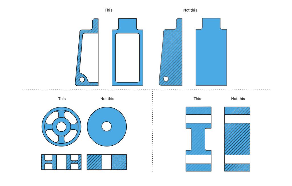
13 MIM DESIGN CRITERIA As injection molding is employed as the shape forming process step in MIM, part designs can avoid the limitations of traditional metalworking processes. With MIM, as is the case with plastic injection molding, design engineers have the freedom of starting with a clean slate, and building up their component geometry by placing material only where it s needed for function and strength. 13
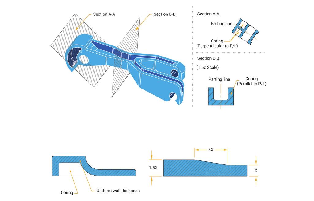
14 MIM DESIGN CRITERIA This benefits both the MIM process and the customer. The very fine metal powders used in the MIM process are expensive, and any opportunity to limit the amount of material required in a component helps minimize the final MIM part cost. Uniform wall thickness Maintaining a uniform wall thickness throughout a component reduces the likelihood of molding process flaws, thus improving the overall part quality, cosmetics, and the resulting dimensional tolerances that the MIM process can provide. If, however, varying wall thickness cannot be avoided, a gradual transition between differing wall thicknesses should be provided and every attempt should be made to avoid abrupt changes. Fig. 3 provides a recommended wall thickness transition ratio for those situations when uniform walls cannot be achieved. 14
15 15
16 MIM DESIGN CRITERIA Coring Coring can be done either parallel or perpendicular to the parting line. Fig.4 illustrates both types of coring, Coring perpendicular to the parting line (Section A-A) can be produced with cores, which are fixed features on either half of the mold. Coring parallel to the parting line (Section B-B) can be produced with slides, which are moving components in a mold. The slides are usually placed at the parting line and move parallel to it. Slides add complexity and costs to a mold, so if the design permits, coring perpendicular to the parting lines is the preferred approach. Remember, when designing a MIM part, or when coring out an existing design, maintaining a consistent uniform wall thickness throughout the part is the primary objective. 16
17 17
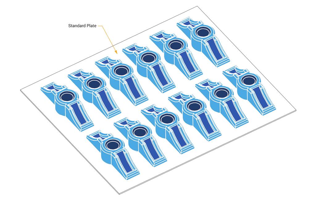
18 MIM DESIGN CRITERIA Sintering supports During the debinding and high temperature sintering processes, molded parts (or green parts) shrink about 20%. While the parts are shrinking and before the parts can fully sinter, the forces of gravity and friction (from shrinking) may distort the parts if they are not adequately supported. Ideally, MIM components should be designed with a large flat surface or with several component features that have a common plane. This design approach allows the use of standard or flat debinding and sintering plates of trays, and eliminates the need for custom or part specific debinding and sintering supports. These custom or part-specific supports can be expensive to produce and represent added tooling costs for the customer. Fig. 5 illustrates a MIM component that is fully supported and placed onto a standard plate without the need for special supports. However, if a single flat surface or plane cannot be provided, part specific debinding and sintering supports will be needed. There are various types of specialized supports that can be used. Ceramic strips are the simplest type of debinding and sintering support. 18
19 19
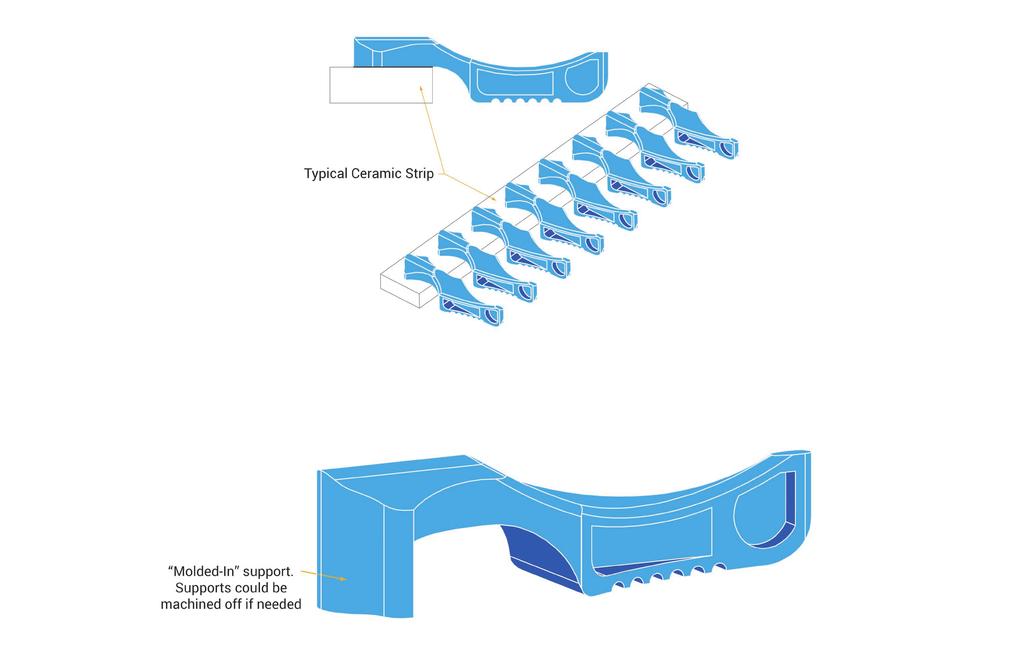
20 MIM DESIGN CRITERIA Ceramic strips If the design permits, ceramic strips can be avoided by designing molded-in supports. This would eliminate the need for the additional tooling costs, but would add a non-functional feature to the component. Fig. 6 illustrates a typical use for a ceramic strip, which is often used to support cantilevered features that could sag in the high temperature sintering process. The strip comes in different heights to meet the finished part s dimensional requirements. 20
21 21
22 MIM DESIGN CRITERIA Ceramic plates Ceramic plates with machined features are more complex and costly than ceramic strips. Attempts are made to minimize the cost of these machined plates by limiting the plate features to holes or grooves. These types of support features are more expensive than simple ceramic stripes, but can fully support features that are more complex. It is also possible to machine custom ceramic plates to support highly complex part geometries. Fig. 7 shows a MIM part that is placed on machined posts. If the part were simply placed on the thin walled legs, the legs would likely drag open when the part shrinks 20% during the sintering process. Placing the part upside down is not an option due to the small feature on the top. The intent of the posts on the custom ceramic plate is to suspend the part so the bottoms of the legs are not making contact with the base of the plate. In this example, the effects of gravity can actually help keep the legs straight. This type of support plate represents one of the most expensive types of supports used by the MIM process. 22
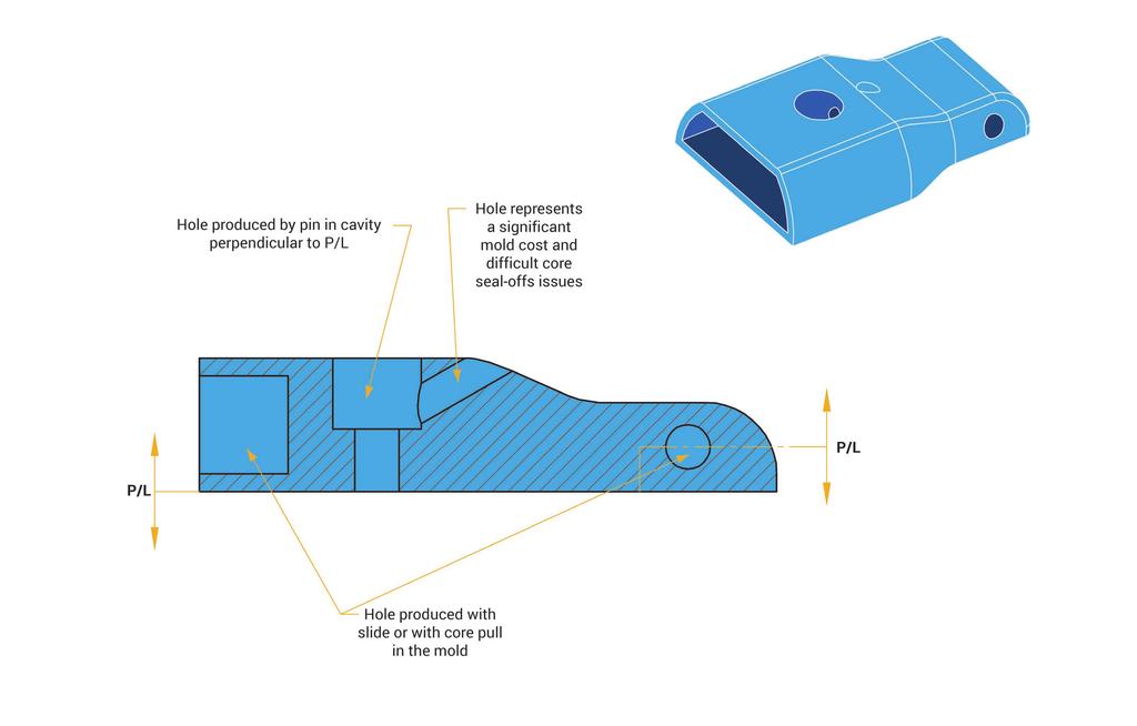
23 23
24 MIM DESIGN CRITERIA Draft where and when required Generally, MIM components do not require draft. There are a couple of factors that contribute to this: Firstly, the MIM feedstock is highly loaded with metal powders that retain heat long after the molding cycle has been completed. Post molding shrinkage which occurs with plastic parts while they are still in the mold, occurs for MIM parts during the first several minutes after they have been removed from the mold. This allows the part to be ejected before it can cool and shrink around cores and/or other mold cavity features. Secondly, the polymer binder used in MIM feedstock acts as a lubricant to assist in the ejection of the part from the mold cavity. With these influences in mind, there are circumstances when draft should be provided in MIM component designs. 24
25 Draft Slight taper on internal walls Offsets effects of shrinkage Ejector pins easily push out the casting (from cavity) 25
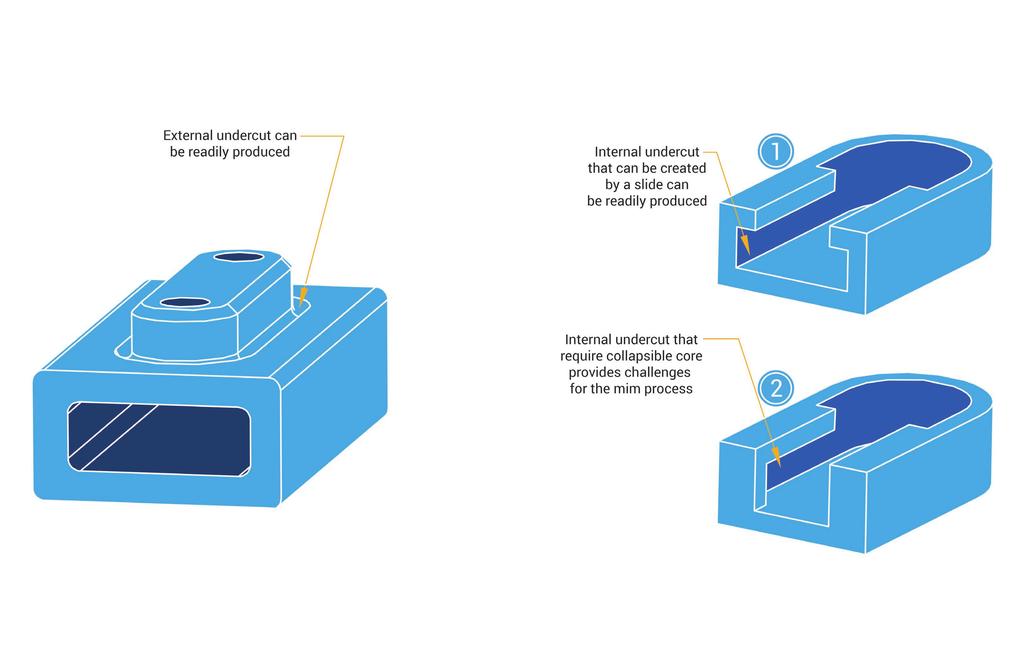
26 MIM DESIGN CRITERIA Corner breaks and fillets One of the intrinsic benefits of MIM is the ability to produce corner breaks and fillets. Not only do corner breaks and fillets play several important roles in a good MIM component design, they also provide design engineers with design advantages not readily available in some metalworking processes. In addition to providing improved injection molded part quality, these design advantages include: Improved part strength Elimination of stress concentrations Softening of sharp corners for aesthetics and handling Typically, corner breaks should be kept larger.005 radius. Internal and external corner breaks less than.005 radius will induce stress concentrations in the part and will be difficult to fabricate in the mold. 26
27 Radius Fillet Sharp corners should be avoided Design inside corners with fillets Design outside corners with radii Strengthens castings Improves metal flow through reduced turbulence 27
28 MIM DESIGN CRITERIA Fig. 10 illustrates an exception where a sharp corner is preferred over a generous radius. The figure shows a MIM component and mold design that benefits from having sharp corners located on the bottom of the part. In this case, the sharp corners allow the part geometry to be kept in one half of the mold, which simplifies the mold design, reduces the mold cost, and does not jeopardize the part s strength. Should a radius be required along the bottom edge of the part, it can be readily produced, but it should be noted that the part must now have portions of it produced in each half of the mold. In addition to adding cost to the mold, the designer should expect a witness line around the profile of the part at the parting-line location. 28
29 Parting Line Parting Line Geometry is above & P/L Geometry is above & below P/L R.010 Fillet R.015 Typical P/L P/L P/L P/L Sharp corners on the bottom allows all of the geometry to stay above the parting line, thus reducing tooling costs Corner breaks on the top & bottom requires portions of the part to be in both halves of the mold which adds to the tooling costs P/L P/L P/L P/L 29
30 MIM DESIGN CRITERIA Holes and slots Holes and slots can be easily produced by the Metal Injection Molding process and generally does not cost extra. However adding these features does increase the cost and complexity of the mold. Also, it s important to keep in mind that beyond representing obvious functional features, holes and slots can also be used to reduce part mass and provide uniform wall thicknesses. Type and direction of the hole It s also important to be aware of the type and direction of a hole and how it could affect the cost and the robustness of the mold. Figure 11 shows several types of holes, their direction relative to the parting line, and their impact on the mold. Holes that are perpendicular to the parting line represent the easiest mold design approach and the lowest cost to incorporate in the mold. Holes that are located parallel to the parting line are readily applied, but the tooling costs more than holes located perpendicular to the parting line. This is because they require mechanical slides or hydraulic cylinders to actuate them during part ejection. Holes that are set at an angle to the parting line are also possible, but the mold construction and the mechanism to actuate them becomes very expensive and in many cases the mold features result in more frequent maintenance downtime and related upkeep costs. Cores and slots that intersect with one another can also create complex part features. However, when employing intersecting features, the mold construction and robustness must be considered. Fig. 12 shows the advantages of using a D-shaped hole as an ideal seal-off surface for an intersecting hole. 30
31 31
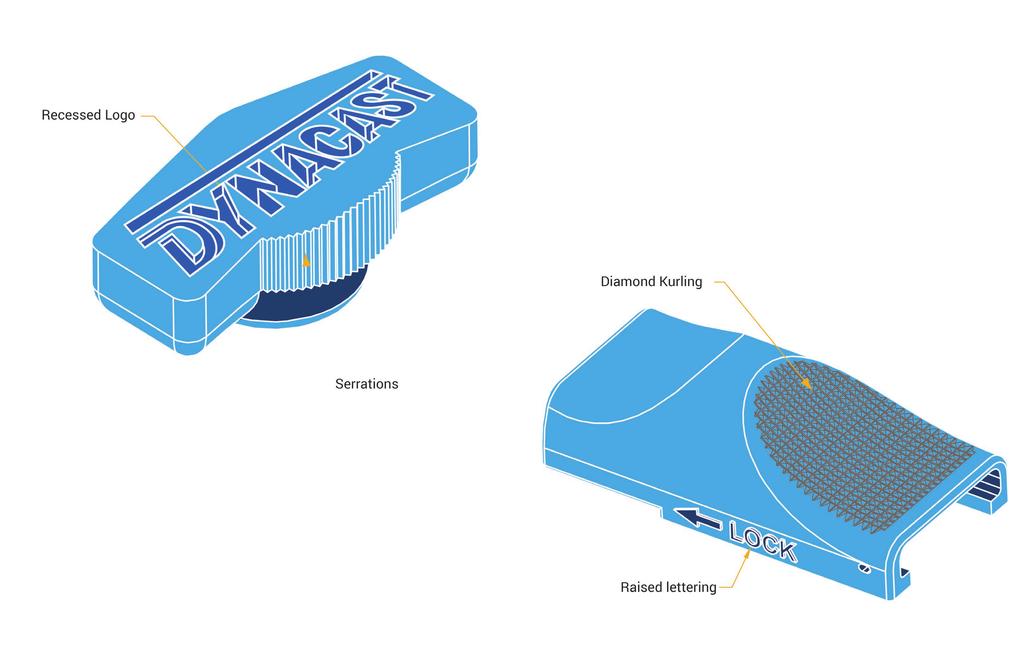
32 32
33 MIM DESIGN CRITERIA In this case two flat surfaces are sealing against one another providing a tool that will be easy to maintain and less likely to generate unacceptable flash during the molding process. The alternative displayed in the figure shows the least attractive approach, which requires one of the cores to have a contoured or profiled face to match the core or hole that it will be sealing against during the injection portion of the molding process. In circumstances like these, the core orientation is critical and the feathered edges are likely to wear more rapidly affecting the shape and size of the molded feature. Mold flash is also a concern in these situations. Undercuts: external and internal External undercuts can be easily produced with the MIM process. The component on the left in Fig. 13 shows an external undercut that provides relief for burrs on a mating stamped component. MIM s ability to provide the feature by placing it in the mold design eliminates the need and related cost associated with removing the burr on the stamping. Essentially the MIM part can be more complex without any associated costs. In addition, the MIM part design eliminates the need for a secondary deburring or chambering process on the stamping. Product assembly requirements should always be considered when designing components to be produced by the MIM process. Internal undercuts are possible with MIM under the right conditions. Internal undercuts that can be produced with a mechanical or hydraulic actuated slide are easy to achieve Fig. 13 also shows a similar component, but this undercut needs the internal feature to be large enough to accommodate a robust collapsible core. 33
34 34
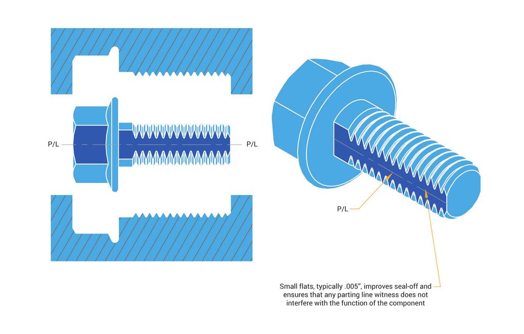
35 MIM DESIGN CRITERIA Generally though, MIM components are small and collapsible cores are often impractical and sometimes impossible to produce. Collapsible cores also provide challenges in maintenance to minimize flash. Please seek advice from our engineers when considering such features. Threads Internal threads can be molded directly into the component using unscrewing cores. These mold features and functions are costly to produce, and as a result, are only utilized in high volume applications. For lower volume part applications, conventional tapping operations are preferable. External threads can be molded directly onto the component, eliminating the need for secondary thread-forming operations. Molding external threads is almost always a more cost effective approach than forming the threads with a secondary operation. Generally, a small flat, typically.005 at the parting line should be incorporated into the design. The recessed flat, shown in Fig. 14, will insure proper mold seal-off and reduce the opportunity for parting line vestige to interfere with component function. Without the presence of a flat along the parting line, you can expect problems with flash to develop in the root of the threads within the production of very few parts. This will likely increase tooling maintenance and down time. 35
36 36
37 MIM DESIGN CRITERIA Ribs and webs Ribs and webs are an efficient way to increase part strength, and minimize the effects of dimensional variation caused by the substantial shrinkage occurring during debinding and sintering. As with plastic injection molding, ribs and webs also improve the molding process and provide better dimensional control. Fig. 15 shows how ribs and webs can be added to improve the mechanical design and provide a more robust MIM component. Another application of ribs is where they are used as a means to provide coring for part mass reduction without effecting the intended end use or strength of the component. 37
38 Tabs may be weak and could distort during debinding and sintering Adding Ribs & Webs will strengthen part and minimize distortions 38
39 MIM DESIGN CRITERIA Knurling, lettering, and logos MIM is also capable of producing knurling, lettering, logos, date coding, or other designs directly onto the component without added costs to the piece price. These features can either be raised or sub-surface. Fig. 16 depicts an example of this. MIM provides high levels of feature detail, including relatively sharp diamond knurling. Virtually any feature you can imagine molding is possible in solid metal parts with the MIM process. 39
40 40
41 MIM DESIGN CRITERIA Gating: Types & Locations In most cases, gates are located at the parting line of the mold. The impact of the gate location on the component must be considered during the design phase, as it can be a careful balance between manufacturability, part function, dimensional control, and aesthetics. Gates will leave a slight vestige, and should not be located on a dimensionally or a visually critical surface. Fig.17 shows an illustration of an edge gate. In general, the gate is placed at the thickest crosssection to allow the material to flow from thick to thin cross-sections. Additionally, the location of the gate(s) should be placed to allow uniform filling of the mold cavity. The following characteristics are typical for an edge gate: Gates are typically removed manually and are not suited for high annual volume applications. Suited for low to medium annual volume applications. Recessed gates are preferred to minimize vestige above functional component surfaces. Normally located along the parting line. 41
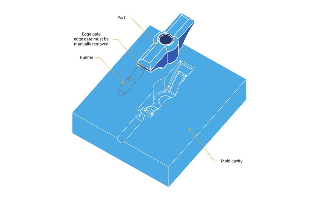
42 42
43 MIM DESIGN CRITERIA Fig.18 shows a submarine or sub-gate, which has the following characteristics: The gate is automatically sheared off from the part during the part ejection portion of the molding process. Suited for low to high annual volume applications. Leaves minimal gate vestige or breaks off below the surrounding component surface. Sub-gates should be placed on a recessed surface to minimize vestige above functional component surfaces. 43
44 44
45 MIM DESIGN CRITERIA Fig. 19 illustrates a submarine or sub-gate to a removable post. This gating approach has the following characteristics: The gate is automatically sheared off from the post during the part ejection portion of the molding process. The post is removed after the part is out of the mold, and this removal process is not typically automated. The post is preferably located in a recessed pocket on the MIM component so the post can be broken off below the component surface. Suited for low to medium annual volumes. The post and related recess or pocket should be located on a non-cosmetic surface. Other gating techniques common to plastic injection molding can also be applied to MIM parts including, 3-plate molds with direct gating, and hot-runner systems for direct gating. Generally, any technique utilized in plastic injection molding can be applied to the MIM process. 45
46 46
47 MIM DESIGN CRITERIA Sink and knitlines Similar to a plastic injection molded part, a MIM part may contain sinks and knit-lines caused by improper part and mold design. Sink (a physical depression on the surface of a part) frequently occurs around thicker sections. The example shown in Fig. 20 illustrates how sink can occur when a supporting rib intersects a wall. If the rib is the same thickness as the wall, the intersection of the two, creates a localized thick wall and is susceptible to sink. Decreasing the thickness of the supporting rib eliminates or reduces the potential for sinks. Generally, the thickness of the rib should be about 75% of the thickness of the wall. Knit-lines can occur when two flow paths of material meet in the cavity when the flow path is relatively long. Fig. 21 shows a knit-line occurring in a cylindrical part with a core in the center and a single gate. The two flow paths have to go around the core before meeting on the opposite side. Due to the long flow path, the two flow fronts of material have cooled down, which creates a visually evident knit-line. Fig. 21 also shows how dual gating the part can substantially reduce, and at times, eliminate visible knit-lines. You should keep in mind that visually negligible knit-lines on properly designed MIM parts are superficial and do not represent a structural defect or part performance issue. Generally, knit-lines of this type have a shallow witness that is a little as.0005 deep to.005 deep. 47
48 X X SINK X ~0.75X RIB RIB KNITLINE SINGLE GATE DUAL GATE 48
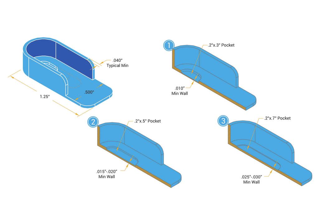
49 MIM DESIGN CRITERIA Minimum and maximum wall thickness The minimum or maximum cross sectional wall thickness on any part is very much dependent on the overall part size and design. The most important issue to keep in mind is the ability to fill the part during the molding step of the MIM process. As an example, a wall thickness may be possible if it s localized, but is not possible if it is across the entire length of a 4 long part. Generally, the optimum wall thickness is to and again, it s related to the overall size of the part. thin wall. The figure illustrates a general guideline of the minimum wall thickness possible, depending on the size of the pocket. At the other end of the spectrum, wall thicknesses as large as are possible, but as the wall thickness increases, so does the molding process cycle time, material consumption, debinding and sintering cycles. Each of these increases represents an increase in the part cost. Minimizing wall thickness also reduces the material content of a part and its cost. Fig. 22 shows a MIM part with a small pocket with a 49
50 50
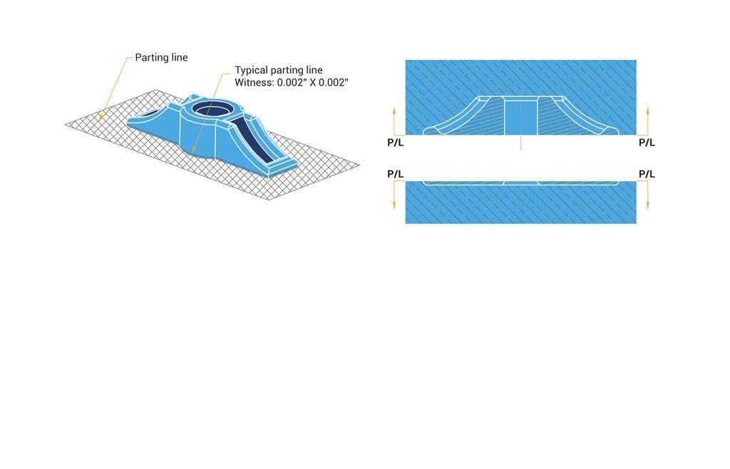
51 MIM DESIGN CRITERIA Flash and witness lines When designing a MIM component, witness lines and areas of potential flash should be taken into consideration. Critical areas from both an aesthetic and functional standpoint should be assessed for possible effects of witness lines or for minimizing the potential for flash. It should be noted that MIM feedstock tends to flash more readily than most plastic materials, and as a result, MIM molds require very precise fits between each of the mold components such as slides, cores, and parting line. Remember, flash generated on a MIM part becomes a metal burr after sintering and is difficult to remove. Witness lines are an unavoidable result of two mating mold components. Whether along a parting line, or where a core pin seals off against a slide or other mold feature, injection molded material under pressure will be imprinted with the witness mark of two pieces of steel meeting one another. Fig. 23 illustrates the typical witness line to be expected along a parting line. In this example, the parting line is just above the fillet and the part will have a witness mark all around the part at that point. The witness line can often be minimized or removed with a secondary tumbling operation. 51
52 52
53 MIM DESIGN CRITERIA As discussed in the Corner Breaks and Fillets section of this design guide, if the bottom fillet is not needed and a sharp corner can be tolerated, the full part geometry can be kept in the upper half the mold. This will move the parting line to the bottom of the part and no witness line will be present. A tumbling operation can also be performed which will give the part a slight corner break as an alternative to containing the part geometry in both mold halves in order to accommodate a radius along the edge of the part. How to avoid flash The potential for flash will always exist and in many cases the construction of the mold plays a big role in minimizing this potential. However, there are design actions that can be taken that will improve the robustness of the mold, thereby decreasing the chances of flash on the part. One major way for avoiding flash is to have flaton-flat, contact for the mold seal-off features. Fig. 24 shows how an intersection of two holes can be redesigned to reduce the potential of flash using a D-shaped hole as an ideal seal-off surface for the intersecting hole. In this case, two flat surfaces are sealing against one another providing a tool that will be easy to maintain and less likely to generate unacceptable flash during the molding process. The alternative displayed in the figure shows the least attractive approach, which requires one of the cores to have a contoured or profiled face to match the core or hole that it will be sealing against during the injection portion of the molding process. In circumstances like these, the core orientation is critical and the feathered edges are likely to wear more rapidly affecting the shape and size of the molded feature. Mold flash is also a concern in these situations. 53
54 54
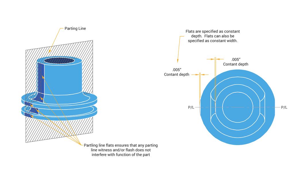
55 MIM DESIGN CRITERIA Whenever possible, areas of potential flash and/ or witness lines are moved away from critical areas. In the circumstances where this is not possible, there may be alternatives to ensure any witness lines and/or flash does not interfere with the function of the part. Fig. 25 illustrates one of these alternatives. On a cylindrical component with an external undercut, the parting line would run lengthwise, down the center of the part. To avoid a situation where any witness on the O.D. could interfere with the function of the component, small flats are added along the parting line to ensure that any witness line and/or flash would occur below the functional diameter of the part. 55
56 56
57 MIM DESIGN CRITERIA Interchangeable mold inserts Multiple parts that have only minor variations between them may be produced using interchangeable mold inserts. All common features are produced by the cavity, but the unique feature is produced with an insert that can be pulled out and replaced with another insert containing an alternative feature. Fig. 26 illustrates a mold with interchangeable inserts to produce two different parts. Sharing a common mold and utilizing inserts minimizes the tooling fabrication needed, providing tooling cost savings. As with any metal-to-metal seal-off areas, there will be a slight witness mark on the part and this should be taken into consideration during the design stage. It should also be noted that interchangeable inserts can generally be accommodated on low to medium volume parts, but high annual volume applications are normally better served with independent molds for each part design configuration. 57
58 58
 This compares to the investment casting process with tolerances of: +/- 0.5% of nominal (i.e. 1000 +/-.")
59 DIMENSIONAL TOLERANCES As a starting basis, MIM is capable of as-sintered tolerances of: +/- 0.3% of nominal (i.e /-.003 ) This compares to the investment casting process with tolerances of: +/- 0.5% of nominal (i.e /-.005 ) 59
60 DIMENSIONAL TOLERANCES The exact tolerance capability on any feature is influenced by a variety of variables that are inherent in the MIM process. The resulting tolerance capability may be less than +/- 0.3% noted above or greater in some cases. Variables such as part design, size, shape, material, gate location, number of cavities and, mold constructions techniques need to be taken into consideration. The material chemistry selected for your application can have a greater effect on tolerances. Not all materials produce the same tolerance results. Gauging or inspection requirements are an integral element of a component design and could have a heavy influence on tolerance capabilities. It has been our experience that theoretical intersections, center of radii, and very small features require larger percentage tolerances due to gauge resolution, repeatability, and capability limitations. Fig.27 shows examples of the typical tolerance requirements for a MIM component without the need for secondary operations. Depending on component geometry, flatness and straightness, specifications of down to.001 inchper-inch are achievable. This is especially true if the entire critical surface can be supported during debinding and sintering, or the critical feature is perpendicular to the supported surface, Gate location, cross-sectional thickness, and crosssectional geometry have an effect on the resulting straightness or flatness. 60
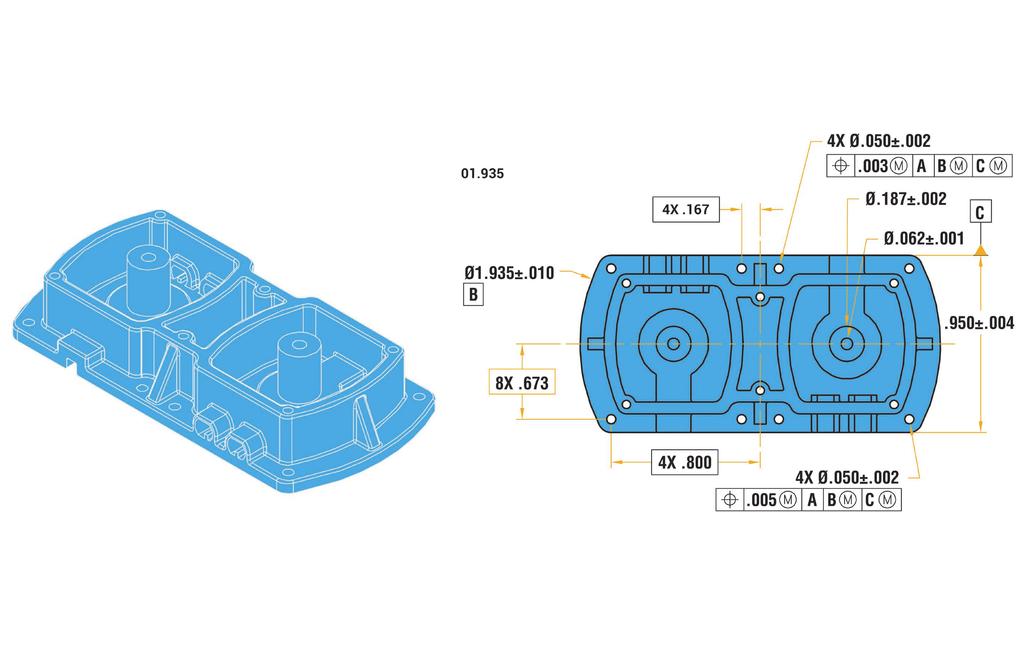
61 61

62 SECONDARY OPERATIONS To minimize the cost of secondary operations, the general tolerance guidelines in this design guide should be applied. Should a feature require a tighter tolerance than the MIM process can offer, a secondary metalworking operation can be performed. Dynacast s MIM materials can be machined, tapped, drilled, broached, sized, ground, or welded like its wrought material counter-parts. When annual volume requirements are high enough, Dynacast develops fully automated secondary operations to minimize the part cost of these added process steps. 62
63 SECONDARY OPERATIONS Heat Treating Similar to wrought components, MIM components can be heat treated to improve strength, hardness and wear resistance. Dynacast s MIM materials respond very well to standard heat treatments used on wrought materials. As an example, Dynacast s MIM 4605 material can be heat treated by standard quench and temper, austemper, induction hardening, or case hardening processes. Various material properties are available on Dynacast s website. Dynacast s Metal Injection Molding process produces components with densities that are generally equal to or greater than 97% of theoretical wrought material densities. The high densities result in as-sintered surface finishes that are typically 32µin Ra. With the addition of secondary operations such as tumbling, grinding, and polishing, surface finishes better than 16µin Ra can be achieved. Information regarding surface finishes can be found in the material information section of our web site. Surface Finishes and Plating Our MIM materials can be readily plated or surface treated with standard processes used on wrought materials with no need for special surface preparations. Examples of some plating and surface treatments offered are: electroless nickel, chrome, zinc, chromate, nickel Teflon, black oxide, and passivation. 63

64 WORLDWIDE MIM EXPERTISE Our dedicated force of design engineers, metallurgists, process engineers, manufacturing operators, and quality engineers, all have substantial experience in MIM. Our experienced technical staff is complemented by state-of-the-art processing analytical equipment and they can assist you with developing MIM applications or converting parts from other manufacturing processes. 64
65 WORLDWIDE MIM EXPERTISE Worldwide MIM expertise If you d like to request a quote or design assistance from Dynacast, you can submit your electronic part data by or through our website. We operate Pro Engineer Wildfire, Inventor and AutoCad/Mechanical Desktop software applications and would prefer to receive native files, but when they are unavailable, CAD files should be submitted in the following formats: pdf,.dxf,.iges,.stp (.step) or surface iges. 65

66 Dynacast works with organizations all over the world, helping bring their ideas to life with the highest quality precision engineered metal components on the planet. Customers can come from virtually any industry consumer electronics, automotive, healthcare, or any other where only the very best is good enough. And each benefits from our 80+ years of experience pioneering the techniques and technologies that have redefined the industry. It means that every customer receives insight and expertise that adds value at every stage of the design and manufacturing process. It s why today, across multiple industries and multiple geographies, Dynacast is the name synonymous with precision metal components. 66
7 WAYS TO IMPROVE YOUR DIE CAST COMPONENTS
 www.dynacast.com 7 WAYS TO IMPROVE YOUR DIE CAST COMPONENTS Design for manufacturing (DFM) is a core methodology that ensures your die cast parts perform to specification and require the minimum of secondary
Taking MIM Tooling To the Next Level. Originally published in The American Mold Builder Magazine, February 2014
 Taking MIM Tooling To the Next Level Originally published in The American Mold Builder Magazine, February 2014 1 Metal injection molding (MIM) merges two established technologies, plastic injection molding
Injection moulding. Introduction. Typical characteristics of injection moulded parts
 Injection moulding Introduction Injection molding is generally used to produce thermoplastic polymers. It consists of heating of thermo plastic materials until it melts and then injecting into the steel
Factors to Consider in Plastic Molded Design
 9 Factors to Consider in Plastic Molded Design Table Of Contents Introduction 3 Design 4 1. Draft... 4 2. Surface Finish... 5 3. Witness Lines... 6 4. Wall Thickness... 6 5. Support/Straight Ribs Thickness...
Investment Casting Design Parameters Guide for Buyer
 Investment Casting Design Parameters Guide for Buyer The following guidelines and technical information outline what an investment casting is capable of offering. It will cover dimensional and structural
Engineering & Design: Coordinate Dimensioning
 s e c t i o n Section Contents NADCA No. Format Page Frequently Asked Questions (FAQ) -2 1 Introduction -2 2 Section Objectives -3 3 Standard and Precision Tolerances -3 4 Production Part Technologies
All About Die Casting
 All About Die Casting FAQ Introduction Die casting is a versatile process for producing engineered metal parts by forcing molten metal under high pressure into reusable steel molds. These molds, called
Design Guide: CNC Machining VERSION 3.4
 Design Guide: CNC Machining VERSION 3.4 CNC GUIDE V3.4 Table of Contents Overview...3 Tolerances...4 General Tolerances...4 Part Tolerances...5 Size Limitations...6 Milling...6 Lathe...6 Material Selection...7
Profiting with Wire EDM
 3 Profiting with Wire EDM Users of Wire EDM 55 Parts made with the wire EDM process are used for machining conductive materials for medicine, chemical, electronics, oil and gas, die and mold, fabrication,
Better by Design: Guidelines for Designing the Perfect Plated Piece
 MPC Technical Library Better by Design: Guidelines for Designing the Perfect Plated Piece Suggestions, tips and design considerations for enhancing plated part appearance, improving performance and facilitating
Injection Molding Design Guide. Design considerations for rapid manufacturing of plastic parts using injection molding
 Injection Molding Design Guide Design considerations for rapid manufacturing of plastic parts using injection molding Table of contents 1 Injection mold tooling process comparison 3 2 Size considerations
POP FOAM S DESIGN GUIDE 20 Things to Know About Designing with PopFoam:
 POP FOAM S DESIGN GUIDE 20 Things to Know About Designing with PopFoam: 1. Why Use PopFoam 2. The PopFoam Process 3. Guidelines for Draft 4. Parting Line 5. Part Length 6. Undercuts 7. Floating Cores 8.
Think like a machinist when creating solid models
 Think like a machinist when creating solid models Article by Milton Florest President Tooling Research Inc. 81 Diamond St. Walpole, MA 02081 Website www.tooling research.com 508 668 1950 Since the introduction
Steel Plate in Oil Rig Blowout Preventer Valves
 Design Problem Steel Plate in Oil Rig Blowout Preventer Valves Introduction Design for Performance Alloy selection Radii and stress reduction Design for Production Mould method Orientation and cores Controlling
Engineering & Design: Coordinate Dimensioning
 SECTION Section Contents NADCA No. Format Page Frequently Asked Questions (FAQ) -2 1 Introduction -2 2 Section Objectives -3 3 Standard and Precision Tolerances -3 4 Production Part Technologies -4 5 Die
DESIGN & ASSEMBLY GUIDE. D-M-E Collapsible Core and Collapsible Mini-Core
 DESIGN & ASSEMBLY GUIDE D-M-E Collapsible Core and Collapsible Mini-Core TABLE OF CONTENTS D-M-E Collapsible Core & Collapsible Mini-Core This data is designed to assist you in using the D-M-E Collapsible
Design Guidelines for Injection Molding
 Design Guidelines for Injection Molding TABLE OF CONTENTS INTRODUCTION TO INJECTION MOLDING A. Where is it used? B. Importance of prototyping C. Types of prototypes INJECTION MOLDING BASICS A. The machine
Solidification Process(1) - Metal Casting Chapter 9,10
 - Metal Casting Chapter 9,10") Solidification Process(1) - Metal Casting Chapter 9,10 Seok-min Kim smkim@cau.ac.kr -1- Classification of solidification processes -2- Casting Process in which molten metal flows by gravity or other force
Solidification Process(1) - Metal Casting Chapter 9,10 Seok-min Kim smkim@cau.ac.kr -1- Classification of solidification processes -2- Casting Process in which molten metal flows by gravity or other force
Permanent Mold Casting Processes. Assoc Prof Zainal Abidin Ahmad Department of Manufacturing & Ind. Eng.
 Assoc Prof Zainal Abidin Ahmad Department of Manufacturing & Ind. Eng. Universiti Teknologi Malaysia Permanent Mold Casting Processes Gravity die casting Pressure die casting Low pressure High pressure
SHAPED BY INNOVATION.
 SHAPED BY INNOVATION www.fishercast.com Engineering the best value At FisherCast Global, we are committed to engineering cost-effective, innovative manufacturing solutions for your small component production
Chapter 1 Sand Casting Processes
 Chapter 1 Sand Casting Processes Sand casting is a mold based net shape manufacturing process in which metal parts are molded by pouring molten metal into a cavity. The mold cavity is created by withdrawing
Precision Castings Division. Cost Drivers and Design Considerations for Investment Casting
 Precision Castings Division Cost Drivers and Design Considerations for Investment Casting Contents INVESTMENT CASTINGS... 3 WHY INVESTMENT CASTINGS?... 3 SPOKANE INDUSTRIES INVESTMENT CASTING PRODUCTION
Design for Manufacturability Guide
 Design for Manufacturability Guide WHO WE ARE Short-to-medium run metal stamping manufacturer Annual volume of 250 to 300,000 per part number We serve a very diversified mix of customers & markets Our
Stock Materials Interior Fillets... 10
 Rapid Machining Overview... 3 Capabilities... 4 Certifications & Registrations... 4 Stock Materials... 5 Design Guidelines Tolerances... 6 Wall Thickness... 7 Outside Corners... 8 Hole Depth... 9 Interior
Design Guidelines. Pressure Forming
 Design Guidelines For Pressure Forming Plastics Design & Manufacturing Centennial, Colorado Pressure Forming 101 This checklist is a guideline for the design and development of pressure formed parts in
Metal Working Processes
 Metal Working Processes Bachelor of Industrial Technology Management with Honours Semester I Session 2013/2014 CLASSIFICATION OF MANUFACTURING PROCESSES TOPIC OUTLINE What is Sheet Metal? Sheet Metalworking
3D Printing Technologies for Prototyping and Production
 3D Printing Technologies for Prototyping and Production HOW TO LEVERAGE ADDITIVE MANUFACTURING TO BUILD BETTER PRODUCTS ADDITIVE MANUFACTURING CNC MACHINING INJECTION MOLDING Architects don t build without
DIRECT METAL LASER SINTERING DESIGN GUIDE
 DIRECT METAL LASER SINTERING DESIGN GUIDE www.nextlinemfg.com TABLE OF CONTENTS Introduction... 2 What is DMLS?... 2 What is Additive Manufacturing?... 2 Typical Component of a DMLS Machine... 2 Typical
This Injection Mold Standard is used for the design and fabrication of Plastic Injection Molds.
 This Injection Mold Standard is used for the design and fabrication of Plastic Injection Molds. 1. Mold Design 1.1. A preliminary mold design review will be conducted, preferably with the customer present,
The jigs and fixtures are the economical ways to produce a component in mass production system. These are special work holding and tool guiding device
 The jigs and fixtures are the economical ways to produce a component in mass production system. These are special work holding and tool guiding device Quality of the performance of a process largely influenced
University of Arizona College of Optical Sciences
 University of Arizona College of Optical Sciences Name: Nachiket Kulkarni Course: OPTI521 Topic Plastic Injection Molding Submitted to Prof. J. Burge Date 1. Introduction In daily life, we come across
Precision Manufacturing
 Precision Manufacturing 216 North Main Street. Freeport, NY 11520 Phone: 888-260-7466 / Fax: 516-771-6444 sales@ondrivesus.com www.ondrivesus.com Know Linear Your Shaft Shoulder Supports Screws By Dennis
Built-Rite Tool & Die
 Studio System case study 01 Built-Rite Tool & Die Injection molding firm investigates quick-turn mold application, identifies 90% cost savings. 02 Built-Rite cavity insert installed in the mold plate.
ROOP LAL Unit-6 Lathe (Turning) Mechanical Engineering Department
 Mechanical Engineering Department") Notes: Lathe (Turning) Basic Mechanical Engineering (Part B) 1 Introduction: In previous Lecture 2, we have seen that with the help of forging and casting processes, we can manufacture machine parts of
Notes: Lathe (Turning) Basic Mechanical Engineering (Part B) 1 Introduction: In previous Lecture 2, we have seen that with the help of forging and casting processes, we can manufacture machine parts of
Extrusion. Process. The photo below shows a typical thermoplastic extruder.
 Extrusion This process can be compared to squeezing toothpaste from a tube. It is a continuous process used to produce both solid and hollow products that have a constant cross-section. E.g. window frames,
3D Systems Guide to Prototyping Die Cast Parts
 3D Systems Guide to Prototyping Die Cast Parts Tom Mueller 3D Systems May 2013 Table of Contents Introduction... 3 Why should I prototype?... 4 What are the options for Prototyping?... 5 Which should I
Molded Parts and Mold Design
 Molded Parts and Mold Design July 29, 2009 Introduction Importance of Proper Mold Design Design Considerations Overview of Design Process SolidWorks & Mold Design Overview of Mold Design Most common method
Trade of Toolmaking. Module 5: Press Tools, Jigs & Fixtures, Mouldmaking Unit 10: Mould Assembly Phase 2. Published by
 Trade of Toolmaking Module 5: Press Tools, Jigs & Fixtures, Mouldmaking Unit 10: Mould Assembly Phase 2 Published by SOLAS 2014 Unit 9 1 Table of Contents Document Release History... 3 Unit Objective...
Design Guide: Sheet Metal Fabrication VERSION 2.1
 Design Guide: Sheet Metal Fabrication VERSION 2.1 SHEET METAL GUIDE V2.1 Table of Contents Overview...3 Tolerances...4 General Tolerances...4 Wall Thickness...5 Bends...5 Curls...6 Countersinks...6 Hems...7
Two Categories of Metal Casting Processes
 Two Categories of Metal Casting Processes 1. Expendable mold processes - mold is sacrificed to remove part Advantage: more complex shapes possible Disadvantage: production rates often limited by time to
Mould Precision Co., Ltd
 Mould Precision Co., Ltd Program Name: Part Name: Tool Name: Tool source: Tool Steel: Resin: Finished Mould Checklist Program No.: MP15016 NL00326-2G rev04 Part No.: MP15016 Tool No.: MP15016 Customer:
Quality Procedure QP159 General Requirements for Machined Parts
 1. PURPOSE 1.1. This procedure provides general product fabrication requirements. It also provides interpretation of certain requirements specified on product drawings, models, and electronic files. 2.
PROVIDENT DESIGN CHECKLIST
 PROVIDET PROCUREMET WWW.PROVPROCURE.COM PLASTIC IJECTIO MOLD DESIG CHECKLIST MOLD DESIG CHECKLIST PROVIDET PROCUREMET ITRODUCTIO Before you start with a new Mold you need to get as MUCH information on
Mold Design. 5. Mold Structure. Bong-Kee Lee School of Mechanical Engineering Chonnam National University
 5. Mold Structure Bong-Kee Lee Chonnam National University the simplest and most reliable design has the fewest number of moving parts and is more straightforward to manufacture and run in production is
What makes Investment Casting one of the BEST way to cast metal?
 What makes Investment Casting one of the BEST way to cast metal? In it s simplest form, investment casting can be thought of as the melting and flowing of any of todays common engineering metals and alloys
Tooling Approving Report
 Project Name: Part Name: Tool Name: Tool source: Tool Steel: Resin: Project Number: Part Number: Tool Number: Customer: No of Cavities: Machine Size: CAVITY What is the customer required core hardness?
Mould Precision Co., Ltd
 Program Name: Part Name: Tool Name: Tool Source: Tool Steel: Resin: NL9502 314501 MP1425 Mould Precision Co., Ltd Finished Mould Checklist H13 HRC 48-52 ABS HF380(LG Chem) Program No.: Part No.: Tool No.:
Module 3 Selection of Manufacturing Processes
 Module 3 Selection of Manufacturing Processes Lecture 4 Design for Sheet Metal Forming Processes Instructional objectives By the end of this lecture, the student will learn the principles of several sheet
UNIT 9 TOOLS FOR BASIC LAYOUT
 UNIT 9 TOOLS FOR BASIC LAYOUT Tools for Basic Structure 9.1 Introduction Objectives 9.2 Tools for Scribing 9.3 Accessories 9.4 Summary 9.5 Key Words 9.1 INTRODUCTION The process of making reference mark
EVERYTHING TO KNOW ABOUT OVERMOLDED CABLE ASSEMBLIES
 EVERYTHING TO KNOW ABOUT OVERMOLDED CABLE ASSEMBLIES By Brian Morissette, Cable Assembly Product Manager Epec Engineered Technologies Overmolding has dramatically changed the appearance and functionality
600 Cannonball Lane O Fallon, MO Bruce Willson.
 600 Cannonball Lane O Fallon, MO 63366 Bruce Willson http://www.ofalloncasting.com/ Definition of an Engineer o Someone who knows almost everything o About almost nothing 70 95% of total Product Cost is
Guide to Prototyping. Die Cast Parts. Applications and Technologies of Die Cast Prototyping
 Guide to Prototyping Die Cast Parts Applications and Technologies of Die Cast Prototyping Table of Contents 1 Introduction 3 2 Why Should I Prototype? 4 3 What are the Options for Prototyping 5 Which Should
White paper. Exploring metal finishing methods for 3D-printed parts
 01 Exploring metal finishing methods for 3D-printed parts 02 Overview Method tested Centrifugal disc Centrifugal barrel Media blasting Almost all metal parts whether forged, stamped, cast, machined or
Maximum Part Size with Sinter-1. X: mm (9.25 ) Y: 68.3 mm (2.69 ) Z 1: 65.5 mm (2.58 ) Z2: 80.0 mm (3.19 ) R: 55.5 mm (2.
 Y: 68.3 mm (2.69 ) Z 1: 65.5 mm (2.58 ) Z2: 80.0 mm (3.19 ) R: 55.5 mm (2.") Metal X esign Reference Sheet Listed dimensions are as designed for your final part unless otherwise specified. These guides serve as recommendations and may not reflect all implementations, since 3 printing
Metal X esign Reference Sheet Listed dimensions are as designed for your final part unless otherwise specified. These guides serve as recommendations and may not reflect all implementations, since 3 printing
Metal Mould System 1. Introduction
 Metal Mould System 1. Introduction Moulds for these purposes can be used many times and are usually made of metal, although semi-permanent moulds of graphite have been successful in some instances. The
Injection Molding from 3D Printed Molds. A study of low-volume production of small LDPE parts FORMLABS WHITE PAPER:
 FORMLABS WHITE PAPER: Injection Molding from 3D Printed Molds A study of low-volume production of small LDPE parts August 25, 2016 Formlabs and Galomb Inc. formlabs.com Table of Contents Introduction........................
DESIGN GUIDE >> CNC MACHINING. Quotes in Hours. Parts in Days. rapidmanufacturing.com
 Quotes in Hours. Parts in Days. rapidmanufacturing.com Contents 03 Overview 03 Capabilities 03 Certifications & Registrations 04 Stock Materials DESIGN GUIDELINES 04 Tolerances FINISHING 12 Threads 13
Dicing Through Hard and Brittle Materials in the Micro Electronic Industry By Gideon Levinson, Dicing Tools Product Manager
 Dicing Through Hard and Brittle Materials in the Micro Electronic Industry By Gideon Levinson, Dicing Tools Product Manager A high percentage of micro electronics dicing applications require dicing completely
Addressing Tooling and Casting Requirements at the Design Stage. Whitepaper. Bhaskar Sinha
 Addressing Tooling and Casting Requirements at the Design Stage Whitepaper Bhaskar Sinha Contents Abstract... 2 Introduction... 2 Casting Guidelines... 2 Wall Thickness... 2 Mold Wall thickness... 3 Ribs...
C-Clamps and Lifting Eyes (Eye Bolts)
") 0-C-Clamps & Lifting Eyes-R 2/21/08 9:42 PM Page 1 C-Clamps A B C Armstrong C-Clamps When your requirements call for clamps, specify Armstrong the most accepted name in the business. When you see Armstrong
0-C-Clamps & Lifting Eyes-R 2/21/08 9:42 PM Page 1 C-Clamps A B C Armstrong C-Clamps When your requirements call for clamps, specify Armstrong the most accepted name in the business. When you see Armstrong
Design for machining
 Design for machining Machining processes are material removal processes which are a family of shaping operation in which excess or undesired material is removed from the work piece finally remaining with
Other Types Of Bushes
 Other Types Of Bushes Circuit board drill bushes: Designed to accommodate larger shank for making drill on circuit board Chip breaker bushes: Designed with chip breaking notch. Reduces friction and heat
BUYER S GUIDE TO CONTROLLED TOLERANCE STAMPINGS
 36 WAYS TO MAKE YOUR SHORT RUN STAMPING MORE ECONOMICAL BUYER S GUIDE TO CONTROLLED TOLERANCE STAMPINGS 7 TH EDITION Wrico Controlled Tolerance Stampings There Is A Difference! Wrico Does It Better A privately
Recommended Dimensional Guidelines for Single Screws
 The Society of the Plastics Industry s Machinery Component Manufacturers Division Recommended Dimensional Guidelines for Single Screws The following recommendations for single screws of injection molding
Processing of Non-Metals Prof. Dr. Inderdeep Singh Department of Mechanical and Industrial Engineering Indian Institute of Technology, Roorkee
 Processing of Non-Metals Prof. Dr. Inderdeep Singh Department of Mechanical and Industrial Engineering Indian Institute of Technology, Roorkee Module - 4 Plastics: Properties and Processing Lecture - 5
Engineering & Design: Additional Specification Guidelines
 Section Contents NADCA No. Format Page Frequently Asked Questions (FAQ) -2 s e c t i o n Introduction -2 1 Pressure Tightness G--1-15 Guideline -3 2 Fillets G--2-15 Guideline -4 3 Ribs and Corners G--3-15
Basic Modeling: Mold Seam Profiles
 Special Edition Modeling Reference Basic Modeling: Mold Seam Profiles By Michael D. Roof Jeffrey A. Nelson AMPS #1632 AMPS #2102 AMPS Central SC Wildcats Manufacturing Flaws on Injection Molded Kit Parts
Understanding the Wire EDM Process
 5 Understanding the Wire EDM Process 81 Accuracy and Tolerances Wire EDM is extremely accurate. Many machines move in increments of 40 millionths of an inch (.00004") (.001 mm), some in 10 millionths of
Manufacturing Sun Cartridge Cavities
 Manufacturing Sun Cartridge Cavities The following Technical Tip discusses a variety of points that should be considered when manufacturing a Sun cavity. Many of the items discussed could be classified
Precision Folding Technology
 Precision Folding Technology Industrial Origami, Inc. Summary Nearly every manufacturing process has experienced dramatic improvements in accuracy and productivity as well as declining cost over the last
Special Casting Process. 1. Permanent mould casting
 Special Casting Process 1. Permanent mould casting A permanent mold casting makes use of a mold or metallic die which is permanent.molten metal is poured into the mold under gravity only and no external
Quality Screw Machine Components For The OEM
 Quality Screw Machine Components For The OEM Description Screw Machine Specialties supplies precision screw machine parts and assemblies to world class OEM s in a wide variety of industries and markets.
From Plate Materials & Services - To To COMPLETE PRESS FRAMES
 From Plate Materials & Services - To To COMPLETE PRESS FRAMES Press Press Weldments Weldments & & Assemblies: Assemblies: Superior has Superior has specialized specialized in these in these unique Heavy
AUTOMATED MACHINE TOOLS & CUTTING TOOLS
 CAD/CAM COURSE TOPIC OF DISCUSSION AUTOMATED MACHINE TOOLS & CUTTING TOOLS 1 CNC systems are used in a number of manufacturing processes including machining, forming, and fabrication Forming & fabrication
CHAPTER 5: MOULDING PROCESS
 CHAPTER OUTLINE CHAPTER 5: MOULDING PROCESS 5.1 INTRODUCTION 5.2 INJECTION MOULDING 5.3 COMPRESSION AND TRANSFER MOLDING 5.4 BLOW AND ROTATIONAL MOLDING 5.5 PRODUCT DESIGN CONSIDERATIONS 1 5.1 Introduction
Why Use. Pilot Assemblies. The New Industry Standard
 Why Use Pilot Assemblies The New Industry Standard This product may be covered by one or more patents or patent applications. See http://www.standardlifters.com/patents.html for details. 01/17 - Rev. 11
14 Key Design guidelines for plastic Injection molded parts.
 14 Key Design guidelines for plastic Injection molded parts. Maybe you got the comments from plastic injection molding factory to say the parts should be modified somewhere. Why? The suggestion from factory
MANUFACTURING TECHNOLOGY
 MANUFACTURING TECHNOLOGY UNIT III THEORY OF METAL CUTTING Broad classification of Engineering Manufacturing Processes. It is extremely difficult to tell the exact number of various manufacturing processes
PAGE 12 : THREAD MEASUREMENT TECHNIQUE (Plated and unplated thread gauges)
") 40-60 Delaware St. MACHINING Part No. PR301 - INDEX- MACHINING SECTION Revision: 01/12/2012 PAGE 1 This Quality Standard applies to all metallic parts unless otherwise specified by drawing or specification.
40-60 Delaware St. MACHINING Part No. PR301 - INDEX- MACHINING SECTION Revision: 01/12/2012 PAGE 1 This Quality Standard applies to all metallic parts unless otherwise specified by drawing or specification.
Introduction to Manufacturing Processes
 Introduction to Manufacturing Processes Products and Manufacturing Product Creation Cycle Design Material Selection Process Selection Manufacture Inspection Feedback Typical product cost breakdown Manufacturing
3D PRINTING & ADVANCED MANUFACTURING DESIGN GUIDELINES: DIRECT METAL LASER SINTERING (DMLS) STRATASYSDIRECT.COM
 STRATASYSDIRECT.COM") 3D PRINTING & ADVANCED MANUFACTURING DESIGN GUIDELINES: DIRECT METAL LASER SINTERING (DMLS) STRATASYSDIRECT.COM WHAT IS DIRECT METAL LASER SINTERING? Direct Metal Laser Sintering (DMLS) is an additive
3D PRINTING & ADVANCED MANUFACTURING DESIGN GUIDELINES: DIRECT METAL LASER SINTERING (DMLS) STRATASYSDIRECT.COM WHAT IS DIRECT METAL LASER SINTERING? Direct Metal Laser Sintering (DMLS) is an additive
CHEMICAL MACHINING (CHM)
") CHEMICAL MACHINING (CHM) Synopsis Introduction Etchant Maskant Techniques of applying maskants Process parameters Advantages Limitations Applications Introduction Use of chemicals to remove material is
CHEMICAL MACHINING (CHM) Synopsis Introduction Etchant Maskant Techniques of applying maskants Process parameters Advantages Limitations Applications Introduction Use of chemicals to remove material is
PERFECT SURFACES WORLDWIDE
 A WELCOME FROM THE TECHNOLOGY LEADER in mass finishing Proverbial ingenuity, coupled with German efficiency and a love of perfection, are the best qualifications for developing successful ways of creating
Design for Quality, Manufacturing and Assembly Prof. G.Saravana Kumar Department of Engineering Design Indian Institute of Technology, Madras
 Design for Quality, Manufacturing and Assembly Prof. G.Saravana Kumar Department of Engineering Design Indian Institute of Technology, Madras Lecture 20 Estimation of Mold Cost for Injection Molding (Dixon
Design of Singe Impression Injection Mould for Lower Bearing Cover
 Design of Singe Impression Injection Mould for Lower Bearing Cover Vishwanath DC Student, M. Tech Government Tool Room and Training Centre Mysuru, India Abstract Injection moulding is one of the techniques
Wire EDM Fundamentals
 2 Wire EDM Fundamentals Revolutionizing Machining 35 Wire Electrical Discharge Machining (EDM) is one of the greatest innovations affecting the tooling and machining industry. This process has brought
Product Information Report Maximizing Drill Bit Performance
 Overview Drills perform three functions when making a hole: Forming the chip The drill point digs into the material and pushes up a piece of it. Cutting the chip The cutting lips take the formed chip away
Catalog October Speedi-Sleeve The quickest and most economical way to repair worn shafts
 Catalog 457027 October 2005 Speedi-Sleeve The quickest and most economical way to repair worn shafts Table of Contents The Speedi-Sleeve concept...3 SPEEDI-SLEEVE, the quickest and most sensible way to
4.0 MECHANICAL TESTS. 4.2 Structural tests of cedar shingles
 4.0 MECHANICAL TESTS 4.1 Basis for the test methodology The essence of deterioration is that while it may be caused by insects, weather, fungi or bacteria, the decay is not identical. Further, no two physical
Multiplying Options. Keith Schneider is a big advocate for additive
 By Christina Fuges Multiplying Options Additive manufacturing s greatest impact for this company is the versatility that has allowed it to offer different solutions than other manufacturers. Keith Schneider
Unit4 31. UnitS 39. Unit 6 47
 Preface..................... xi About the Author......... xiii Acknowledgments... xiv Unit 1 1 Bases for Interpreting Drawings........ I Visible Lines............. 3 Lettering on Drawings... 3 Sketching...
CNC EXPANDING MANDRELS
 CNC EXPANDING MANDRELS ID CLAMPING OFFERS FULL OD PART ACCESS PARALLEL EXPANSION FOR OPTIMUM ACCURACY AND GRIP FORCE LARGE RANGE IN STOCK FOR IMMEDIATE SHIPMENT ROYAL CNC EXPANDING MANDRELS Rigid and Accurate
Part Design and Tooling for Rotational Molding : How to Achieve Success in Every Project
 Blue-Reed, LLC Part Design and Tooling for Rotational Molding : How to Achieve Success in Every Project Blue-Reed, LLC 4191 Courtiff Circle Stow, Ohio 44224 www.blue-reed.com Introduction Greg Stout -
Selection BASIC LINE BASIC LINE PLUS VARIO LINE SERIES TUBE LINE STEEL LINE
 PLUS 30 for cable carriers Support trays page 304 PLUS Guide channels page 305 RCC Rail Cable Carrier page 309 ECC Emergency Cable Carrier page 30 Strain relief devices page 3 Assembly profile bars page
Design consideration for design a flat and ring plastics part using Solidworks software
 IOP Conference Series: Materials Science and Engineering PAPER OPEN ACCESS Design consideration for design a flat and ring plastics part using Solidworks software To cite this article: M A M Amran et al
Typical Parts Made with These Processes
 Turning Typical Parts Made with These Processes Machine Components Engine Blocks and Heads Parts with Complex Shapes Parts with Close Tolerances Externally and Internally Threaded Parts Products and Parts
ET2C International. Low Cost Country Outsourcing/ Sub Contract Manufacture
 ET2C International Low Cost Country Outsourcing/ Sub Contract Manufacture Who Are We For the past 18 years ET2C International have been supporting businesses globally benefit from the advantages of sourcing
Professional Pliers. Quality to Depend on
 Professional Pliers Quality to Depend on - 227 - High Leverage Pliers High Leverage Pliers High Leverage pliers boast a labor-saving design to generate greater productivity with less effort. Ergonomic
Rapid Sheet Metal Overview... 3 Capabilities... 4 Certifications & Registrations... 4 Stock Materials... 5 Design Guidelines Uniform Wall
 Rapid Sheet Metal Overview... 3 Capabilities... 4 Certifications & Registrations... 4 Stock Materials... 5 Design Guidelines Uniform Wall Thickness... 6 Bends... 7 Hems... 8 Offsets... 9 Holes & Slots...
METRIC / IMPERIAL MINI-MAG LEVEL
 Digital Mini-Mag Level 570 Series Measuring range 360 (4 x 90 ) Embedded magnets on three sides Resolution 0.05 Accuracy +/- 0.2 Standard 9V battery Dimensions: L60mm x H60mm x W35mm METRIC / IMPERIAL