midas DShop Reinforcement Edit Function reflecting Constructability
|
|
|
- Nathaniel Douglas
- 5 years ago
- Views:
Transcription

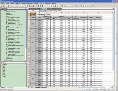
1 01 Auto-generation of Structural Drawings 02 Structural drawings such as Framing plans, Sectional elevations, Beam/Column schedules, etc., are generated from the analysis & design results of midas Gen. Reinforcement Edit Function reflecting Constructability midas DShop provides Reinforcement Edit Function by Members so that users can edit reinforcement data imported from midas Gen in order to reflect constructability. Auto-generation of B.O.M (Bill Of Materials) midas DShop provides accurate B.O.M. reflecting even the splicing and development length of reinforcement for the final design results. Auto-grouping & Group editing Functions by member types midas DShop provides Auto-grouping function for members having identical data (section size, rebar quantity, rebar diameter, spacing & number of rebars). User-editing function for autogrouped results is also provided. Beam/Column Elevation Reinforcement midas Gen Design Results Tie Details of Column/Bracing midas DShop Reinforcement Edit function incorporating constructability Quantity Takeoff (Bill Of Materials)


2 Introduction midas DShop empowers engineers to streamline the design process all the way to generating engineering drawings. midas DShop imports models complete with analysis & design results from midas Gen and automatically generates structural drawings. midas DShop features the Drawing Generation Module & the Drawing Edit Module, which enable engineers to analyze and modify design results to reflect their design intent. Main Features midas Gen design results transformed into auto-generation of structural drawings. (General Notes / Plans / Sections / Elevations / Member Schedules) Reinforced Concrete, Structural Steel & RC/SS composite construction supported. Drawings saved into DWG / DXF file formats. midas DShop Framework Main Menu Working Panel Tools Bar Main Drawing View Model View midas DShop incorporates the advanced knowledge and engineering experience to generate drawings of high quality. midas DShop offers 3 main features: - Drawing Generation for generating various structural drawings, - Reinforcement Edit for updating reinforcement, and - Bill of Materials to display material quantity required for construction. Drawing Generation Module - Auto-placement of reinforcing bars reflecting constructability - Convenient edit for RC reinforcement information DShop midas - Offset adjustment by Object bases Drawing Edit Module - Drawing environment and edit identical to AutoCAD - Drawing for Members (Slab / Beam / Column / Brace / Wall / Foundation) - Variety of symbol generation Plan/Section View Plan/Section View TAB Status Bar Import Analysis & Design results from midas Gen Import [midas Gen Design Results] [midas DShop Drawings]
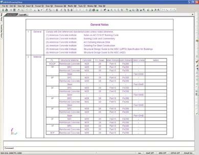
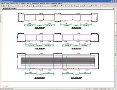
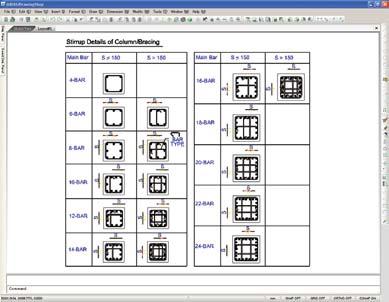
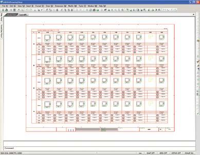
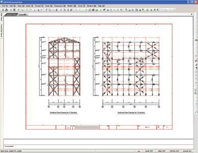
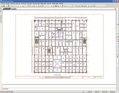
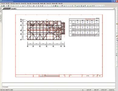
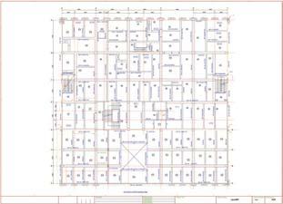
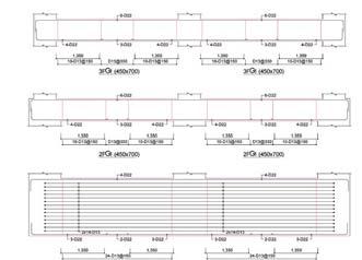
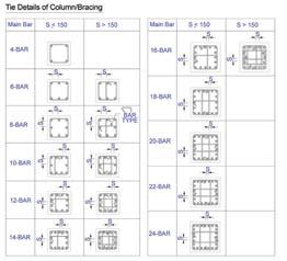
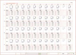


3 Auto-drafting Module for midas Gen General Notes Quantity Takeoff (Bill Of Materials) Framing Plan Beam/Column Elevation Reinforcement Tie Details of Column/Bracing Member List & Schedule Framing Plan Sectional Elevations

 Rebar placement")


 Rebar Placement Specification checking RC")


4 Features Import Analysis & Design results from midas Gen Rebar Placement Specification checking Rebar Auto-placement reflecting constructability Rebar placement specification by members (Beam, Column, Wall & Footing) Rebar placement reflecting constructability - Check for clear spacing of rebars - Specify rebar placement method for constructability - Specify rebar diameters by stories & members Auto-generation of Grid Lines and Marks Mark & Dimension creation / edit function Rebar auto-placement by members reflecting constructability DShop midas Reinforcement Edit function by members (Beam, Column, Brace, Wall & Footing) Auto-grouping & Group editing by member types General Notes Creation / Edit Member offset Edit Drawing Production Environment selection Drawing style & Member Mark Location selection Drawing Form Insertion function Drafting & Editing Auto-generation of B.O.M. (Bill Of Materials) Rebar Placement Specification checking RC reinforcement specification check (Beam, Column, Wall) Structural Steel check RC/SS composite member reinforcement specification check Reinforcement Edit function The Reinforcement Edit function enables engineers to reflect constructability by providing a means to easily modify design results produced by midas Gen. [Editing column reinforcement] [Checking Rebar Design according to Design codes] [Editing reinforcement in Table]


![DShop] Drawing Production](/docs-images/87/97097376/images/5-21.jpg "Environment selection")

5 Auto-drafting Module for midas Gen Auto-generation of B.O.M. The Bill Of Materials function displays the reinforcement material quantity for construction using wall design results. Member Offset Edit function Easy to update the Eccentricities of members to reflect the architectural finishes Offset-Move for Beam, Column, Bracing & Wall Offset-Move by members & groups [Auto-generated quantity takeoff] Drawing Edit (CAD) Drafting & Editing identical to AutoCAD Variety of for drafting by member units Many related to drafting symbols Drawings saved into DWG / DXF file formats Auto-grouping & Group editing Auto-grouping function for members having identical data (section size, rebar quantity, rebar diameter, spacing & number of rebars) User-editing function for auto-grouped results [Auto-grouping by midas DShop] Drawing Production Environment selection Layer, Text Style, Dimension Style & Symbol selection Symbol (Member Mark, Rebar Designation & Grid Mark) selection Saving & recalling selected environment [User Define Grouping]
Auto-drafting Module for midas Gen MIDAS Information Technology Co., Ltd.
 MIDAS Information Technology Co., Ltd. 01 Introduction midas DShop empowers engineers to streamline the design process all the way to generating engineering drawings. midas DShop imports models complete
midas Dshop (Basic Tutorial) Basic Tutorial Reinforced Concrete Structure - 1 -
 Basic Tutorial Reinforced Concrete Structure - 1 -") midas Dshop (Basic Tutorial) midas DrawingShop Basic Tutorial Reinforced Concrete Structure - 1 - Index Ch.1 Summary of Design 1. Summary of Building Model 2. Standards of Structural Design 3. Structural
midas Dshop (Basic Tutorial) midas DrawingShop Basic Tutorial Reinforced Concrete Structure - 1 - Index Ch.1 Summary of Design 1. Summary of Building Model 2. Standards of Structural Design 3. Structural
Architect. Architect.
 The The line line sketch sketch with with modified modified height height for for plinth plinth floor floor is is displayed. displayed. Open Open Architectural Architectural plan plan file, file, which
ProConcrete. Gernot Jeromin Product Manager Bentley Systems, Incorporated
 ProConcrete Gernot Jeromin Product Manager ProConcrete 3D CAD Software for Concrete and Reinforcement 2 WWW.BENTLEY.COM What is ProConcrete AutoCAD Application MicroStation V8i version will be available
CSiDETAILER USER S MANUAL. Detailing and Drawing of Structural Members. Computers and Structures, Inc. Berkeley, California, USA
 CSiDETAILER Detailing and Drawing of Structural Members USER S MANUAL Computers and Structures, Inc. Berkeley, California, USA Version 8.00 August 2004 COPYRIGHT The computer program CSiDETAILER and all
Table of contents. User interface 1: Customizable tool palette... 6 User interface 2: General GUI improvements... 7
 Table of contents WELCOME TO ADVANCE CONCRETE 2014... 5 USER INTERFACE ENHANCEMENTS... 6 User interface 1: Customizable tool palette... 6 User interface 2: General GUI improvements... 7 MODELING... 10
StereoSTATIKA. Main Features:
 A complete software package for 2D/3D Structural Design of Concrete Frames with advanced RC Details by Apostolos Konstandinides www.pi.gr Main Features: Single, user friendly, visual (2D&3D) input of structural
Applied Precast Concrete Detailing
 Applied Precast Concrete Detailing Tekla Structures 11.0 August 30, 2005 Copyright 2005 Tekla Corporation Copyright 2005 Tekla Corporation Applied Precast Concrete Detailing i Copyright 2005 Tekla Corporation
This document has been carefully prepared with all the information needed to properly use this Advance product. This document contains a brief
 This document has been carefully prepared with all the information needed to properly use this Advance product. This document contains a brief description of the software functions and is not a replacement
Number Object Category Attribute Name Explanation Examples Further comments
 1 STORY 2 GRID 3 COLUMN 2 Story Elevation Absolute elevation for story (the name "story" is prefered over "level", as level is used in e.g. Revit Typically, our elevations for a project are all relative
Advance Concrete 2014 Service Pack 1
 Advance Concrete 2014 Service Pack 1 This document describes the improvements in Service Pack 1 for Advance Concrete 2014. GENERAL Interaction between Advance Concrete and Advance Steel. Advance Steel
Dimension Below are the critical settings in AutoCAD. Other software should follow the same settings.
 8.1 Drawing Standard 8.1.1 Introduction This drawing standard applies to all building drawings being prepared for the University of Calgary (UCalgary) by external consultants or vendors and internal staff
Working with Detail Components and Managing DetailsChapter1:
 Chapter 1 Working with Detail Components and Managing DetailsChapter1: In this chapter, you learn how to use a combination of sketch lines, imported CAD drawings, and predrawn 2D details to create 2D detail
Advance Steel Essentials
 Advance Steel Essentials Course Length: 3 days This course is intended to give an overview of all of the basic commands that are required to create structures and associated documentation using the Autodesk
Advance Concrete. Tutorial
 Advance Concrete Tutorial Table of contents About this tutorial... 9 How to use this guide... 10 Lesson 1: Creating a building grid... 11 Step 1: Create a default building grid... 11 Step 2: Set the distances
User s Manual ❿ Drawings-Detailing
 User s Manual ❿ Drawings-Detailing 2 CONTENTS I. THE NEW UPGRADED INTERFACE of SCADA Pro 4 1. UNITS 5 1.1 Drawings-Detailing 5 I. Files 6 II. Drawing 25 III. Formworks 30 IV. Edit 45 V. View 58 VI. Layers
ExtrAXION. Extracting Drawing data. Benefits.
 ExtrAXION Extracting Drawing data ExtrAXION is the simplest and most complete quantity takeoff software tool for construction plans. It has the ability to measure on vector files CAD (dwg, dxf, dgn, emf,
This document has been very carefully prepared in the hope to meet your expectations and to answer all your questions regarding Advance.
 Advance User Guide This document has been very carefully prepared in the hope to meet your expectations and to answer all your questions regarding Advance. This document contains only a brief description
Fundamentals III CHAPTER PROJECT EXERCISE
 CHAPTER 4 Fundamentals III PROJECT EXERCISE This project exercise provides point-by-point instructions for setting up the drawing with layers and then creating the objects shown in Figure P4 1. FIGURE
Advance Steel. Tutorial
 Advance Steel Tutorial Table of contents About this tutorial... 7 How to use this guide...9 Lesson 1: Creating a building grid...10 Step 1: Creating an axis group in the X direction...10 Step 2: Creating
Listed below are the competencies required and examples from the aforementioned job:
 1. Technical Analysis Instructions: Describe a project for which you collected and interpreted or analyzed technical data for development of engineering designs and drawings from concepts and specifications.
Cast Unit Drawings Tekla Structures 11.0 Basic Training August 25, 2005
 Tekla Structures 11.0 Basic Training August 25, 2005 Copyright 2005 Tekla Corporation Contents 11... 3 11.1 Create...4 Define cast unit drawing properties for beams...4 Create a cast unit drawing for a
FOCUS ON REAL DESIGN AUTOMATE THE REST CUSTOMTOOLS BATCH CONVERTING YOUR SOLIDWORKS FILES
 FOCUS ON REAL DESIGN AUTOMATE THE REST CUSTOMTOOLS BATCH CONVERTING YOUR SOLIDWORKS FILES Table of Contents BATCH CONVERTING YOUR SOLIDWORKS DOCUMENTS... 3 Introduction... 3 What does it do?... 3 How does
Chief Architect New Feature List
 SYSTEM / PERFORMANCE Chief Architect Premier X4 is available in 64 bit and 32 bit versions. The 64 bit version is more efficient in managing memory and you will see better performance on larger plan files
Subject Description Form
 Subject Description Form Subject Code Subject Title Credit Value BRE222 Workshop Practices and Draftsmanship 3 Academic Credits Level 2 Pre-requisite/ Co-requisite/ Exclusion Objectives Nil 1) Provide
Release Notes - Fixes in Tekla Structures 2016i PR1
 Release Notes - Fixes in Tekla Structures 2016i PR1, you can now set the to either or. is modified., the ID of the connection plate is not changed anymore when the connection now uses normal rebar groups
Standard 25 Wide Structure
 Standard 25 Wide Structure Truss Arch Style 2 piece 12ft c/c typical Arch Depth 12 Webbing Diameter 1/2 1 run straight 2 runs straight Wind Brace - up to 120 8 Wind Brace - up to 192 12 Wind Brace - over
Release Notes - Fixes in Tekla Structures 2016i SP1
 Release Notes - Fixes in Tekla Structures 2016i SP1 is modified., the ID of the connection plate is not changed anymore when the connection now uses normal rebar groups instead of tapered groups., the
The Rest of the Story: Using Autodesk Inventor Tools to Complete Facilities Design Documentation and Design
 The Rest of the Story: Using Autodesk Inventor Tools to Complete Facilities Design Documentation and Design Instructor: Mike Jolicoeur Autodesk Lab Assistants: Sachlene Singh Autodesk Steve Schuchard PMC
BUILDING PLANS. BUILDING INSPECTIONS DEPARTMENT
 BUILDING PLANS BUILDING INSPECTIONS DEPARTMENT 507-537-6773 www.ci.marshall.mn.us This handout is intended only as a guide to the subject matter covered herein and is based in part on the 2015 Minnesota
One-Stop Solution for Foundation Design
 [Automated Foundation Engineering System] One-Stop Solution for Foundation Design Civil & Architecture Team Jbchoe@gsconst.co.kr 2006.11.02 (Automated Foundation Engineering System) Contents 1. General
Autodesk Architectural Desktop Functionality for the Autodesk Building Systems User
 11/28/2005-1:00 pm - 2:30 pm Room:N. Hemispheres (Salon A1) (Dolphin) Walt Disney World Swan and Dolphin Resort Orlando, Florida Autodesk Architectural Desktop Functionality for the Autodesk Building Systems
Autodesk Revit MEP Learning Essentials Training Course Outline
 Module 00 Revit in a Nutshell Interactive exercise on creating and documenting a basic building Module 01 Introduction to the Principles of BIM Simple Truths Behind the hype The benefits of BIM What will
This specification describes the minimum requirements for structural steel drawings.
 1/7 1.0 PURPOSE This specification describes the minimum requirements for structural steel drawings. 2.0 GENERAL As stated in specification SPEC-0800, drawings are intended to be Design drawings. Sufficient
AutoCAD Architecture 2014
 CADLearning for AutoCAD Architecture 2014 Course Details 19+ hours of training 325 video tutorials Exercise files included Instructor: Reid Addis Course Description CADLearning for AutoCAD Architecture
Advance Steel suite 6.1 / SP2
 Advance Steel suite 6.1 / SP2 This document describes only the improvements in Service Pack 2 compared to Service Pack 1. The installation of SP2 includes SP1; please see the previous document for improvements
12. Pillar rebar arrangement
 12. Pillar rebar arrangement 1) Indication of pillar(c) Main bar drawing - It indicates the length of span by the criterion of pillar and wall, etc. and indicates the position of pillar & wall.
SMART ASSEMBLIES Dimensioning Rules
 SMART ASSEMBLIES Dimensioning Rules EDIT DIMENSIONING RULES Main Element Geometry 1 4 3 1 possible dimensioning options area and notes about current operation 2 preview of selected options effects 3 preview
Revit Structure 2012 Basics:
 SUPPLEMENTAL FILES ON CD Revit Structure 2012 Basics: Framing and Documentation Elise Moss autodesk authorized publisher SDC PUBLICATIONS www.sdcpublications.com Schroff Development Corporation Structural
Drawing a Foundation or Basement Plan
 Appendix F Drawing a Foundation or Basement Plan In this chapter, you will learn the following to World Class standards: Draw a Foundation or Basement Plan Draw the Basement Walls Draw the Pilasters on
Project Booklet. Structural Drafting with AutoCAD
 Project Booklet Structural Drafting with AutoCAD Introduction 1 General Setup 2 Border and Title Block 3 Drafting the Foundation Plan (Plate 1) 8 Drafting the South Elevation (Plate 2) 11 Drafting Section
Table of Contents. What's New in GRAITEC Advance BIM Designers 2018 R2 ADVANCE BIM DESIGNERS CONCRETE SERIES... 4
 What's New 2018 R2 Table of Contents ADVANCE BIM DESIGNERS CONCRETE SERIES... 4 REINFORCED CONCRETE FOOTING DESIGNER... 4 Multi-layer soil calculation... 4 Bottom Constructive Reinforcement... 5 REINFORCED
ARCHITECTURE CADD Course Syllabus
 6111 E. Skelly Drive P. O. Box 477200 Tulsa, OK 74147-7200 ARCHITECTURE CADD Course Syllabus Course Number: TTC-0880 OHLAP Credit: Yes OCAS Code: 8903 Course Length: 120 Hours Career Cluster: Manufacturing
Introduction to QTO. Objectives of QTO. Getting Started. Requirements. Creating a Bill of Quantities. Updating an existing Bill of Quantities
 QTO User Manual Contents Introduction to QTO... 5 Objectives of QTO... 5 Getting Started... 5 QTO Manager... 6 QTO Layout... 7 Bill of Quantities... 8 Measure Folders... 9 Drawings... 10 Zooming and Scrolling...
BIM. e Submission Guideline Structural. Annex 1a. Recommended Process Revit 2010
 BIM e Submission Guideline Structural Annex 1a Recommended Process Revit 2010 Building and Construction Authority 5 Maxwell Road #16-00 Tower Block MND Complex Singapore 069110 www.bca.gov.sg Revision
Section 1 REBAR ARRANGEMENT & CONSTRUCTION CARRYOUT
 Section 1 REBAR ARRANGEMENT & CONSTRUCTION CARRYOUT 1. Understanding of Drawing 1) Examination of drawing When construction contract is completed, the contents of the drawings are surveyed and checked
ROOM smooth cement f.f FLOOR LAYOUT
 3,300 3,600 4,100 2,159 1,000 1,241 ROOM smooth cement f.f 168 900 1,091 1,000 1,241 4,400 FLOOR LAYOUT FLOOR LAYOUT CARTAKERS ROOM 2,159 1,000 1,241 SOUTH ELEVATION EAST ELEVATION 1,241 1,000 1,091 900
WORK BOOK. For BASIC TRAINING ON RGS REBAR. Version 3.0. Last Edited : 31 August 2009.
 WORK BOOK For BASIC TRAINING ON RGS REBAR Version 3.0 Last Edited : 31 August 2009. PREFACE This material is intended to be a Basic Training Workbook for the users of RGS REBAR. The users are advised to
Installation Instructions
 Column & Beam Units with Debris Netting Installation Instructions Laminated Wood Systems, Inc. Seward, Nebraska 800-949-3526 2015 LWS, INC. AVR-NET INSTALL 05-12-16 AVR Installation Notes 1 Safety The
Revit Structure 2014 Basics
 Revit Structure 2014 Basics Framing and Documentation Elise Moss Authorized Author SDC P U B L I C AT I O N S Better Textbooks. Lower Prices. www.sdcpublications.com Powered by TCPDF (www.tcpdf.org) Visit
TABLE OF CONTENTS INTRODUCTION...4
 Starting Guide TABLE OF CONTENTS INTRODUCTION...4 Advance Steel... 4 Where to find information?... 5 INSTALLATION... 5 System requirements... 5 Starting the installation... 5 STARTING ADVANCE STEEL...
Customising Bolt & Hole symbols for StruCad evolution
 Customising Bolt & Hole symbols for StruCad evolution Customization of StruCad Bolt & Hole Symbols for Drawings The creation of customized Bolt & Hole symbols for StruCad Drawings can be achieved simply
EstimaXpro. S&R Consultants
 EstimaXpro S&R Consultants Contents 1. Introduction... 5 2. Masters... 7 2.1 Project Details... 7 2.2 Storey Details... 8 2.3 Joinery Details... 8 2.4 Rate types... 9 2.5 Rates... 9 2.6 Rate Analysis Type...
Architectural Floor Plan Symbols
 Architectural Floor Plan Symbols The symbols below are used in architectural floor plans. Every office has their own standard, but most symbols should be similar to those shown on this page. Building Section
The best Know-how and IT solutions in the Precast Concrete market
 The best Know-how and IT solutions in the Precast Concrete market Software Technology Consultancy www.csgengineering.eu CSG is the European leader for Technical Services in the Precast Concrete market.
Unit 15: Using Symbols and Attributes
 Unit 15: Using Symbols and Attributes Overview Many mechanical drawings use the same geometry over and over. The SI symbol, commonly found on Metric drawings, is one example. AutoCAD allows you create
 www.cad-designers.com Staffing Services Cad Designers is an established staffing company that specializes in providing professional support for the A/E/C industry. All candidates are screened with a complete
The Benefits of Using the Electrical Toolset in AutoCAD
 The Benefits of Using the Electrical Toolset in AutoCAD A productivity study detailing the differences between AutoCAD and the Electrical toolset. Built specifically to create and modify electrical controls
BUILDING PLANS. BUILDING DEPARTMENT
 BUILDING PLANS BUILDING DEPARTMENT 952-446-1660 www.cityofminnetrista.com This handout is intended only as a guide and is based in part on the 2015 Minnesota Residential Code, Minnetrista City ordinances,
[BARLINES MANUAL OF STANDARD PRACTICE (PHILS)]
![[BARLINES MANUAL OF STANDARD PRACTICE (PHILS)]](/thumbs/77/75195914.jpg "[BARLINES MANUAL OF STANDARD PRACTICE (PHILS)]") Chapter Two The items discussed in this chapter are outlined below. Fabrication Bend Class Typical Bar Bends Bar Marks and the use of MK symbol Drafting (CAD) Standards CAD Software Contract or Working
Chapter Two The items discussed in this chapter are outlined below. Fabrication Bend Class Typical Bar Bends Bar Marks and the use of MK symbol Drafting (CAD) Standards CAD Software Contract or Working
Corridors. To create a corridor you must have an alignment (baseline), a profile (existing or proposed), and an assembly.
, a profile (existing or proposed), and an assembly.") Corridors To create a corridor you must have an alignment (baseline), a profile (existing or proposed), and an assembly. Alignments You have 2 choices in defining an alignment: (1) Alignments > Create
Corridors To create a corridor you must have an alignment (baseline), a profile (existing or proposed), and an assembly. Alignments You have 2 choices in defining an alignment: (1) Alignments > Create
Version 8 Tutorial
 Version 8 Tutorial 800-989-4243 214-340-9436 support@vertigraph.com www.vertigraph.com 1 Table of Contents A. Overview... 4 B. About the SiteWorx/OS Window... 4 C. File Types Raster, Vector and PDF...
CADPIPE Industrial Pipe. Tutorial
 CADPIPE Industrial Pipe Tutorial Introduction This Tutorial is a brief introduction to the power of CADPIPE 3D DESIGN. We will show you a few key features and the general procedures for creating 3D piping
24 X32 3 CAR GARAGE POLE BARN STYLE FRAME
 24 X32 3 CAR GARAGE POLE BARN STYLE FRAME 3 ENTRY DOOR 2 WINDOWS, 1 @ EA. END 1-16 X8 GARAGE DOOR 1-9 X8 GARAGE DOOR 4 CONCRETE SLAB 10 WALLS 4/12 PITCH METAL ROOF METAL SIDING INDEX PAGE DESCRIPTION 1
Open Up Your View With CABLE SYSTEMS
 Open Up Your View With CABLE SYSTEMS PRESENTED BY CROWN HERITAGE Our Cable Multiple options to accomodate any deck or stair design Marine Grade 316 stainless steel Swaging is the term used for attaching
Piping Workflow for MEP AutoCAD Piping Phil Nower Hazen and Sawyer
 Piping Workflow for MEP AutoCAD Piping Phil Nower Hazen and Sawyer MP3512-L: In this class we will harness the power of MEP Data in AutoCAD. We will review the workflow to fully utilize this Data throughout
COURSE OUTLINE. Course Number Course Title Credits. Co- or Pre-requisite BCT110 Construction Materials & Methods
 COURSE OUTLINE Course Number Course Title Credits BCT101 Construction Graphics 3 Hours: 2 Lecture 2 Studio/Lab, Co- or Pre-requisite BCT110 Construction Materials & Methods Implementation sem/year Fall
WHO WE ARE. Our Client base. - USA - Canada - Hawaii. - Australia - New Zealand - UAE. - UK - Netherlands - Oman. - Singapore - Norway - Qatar
 WHO WE ARE We help construction companies, general contractors, architects & engineers to seamlessly integrate BIM into their projects within their predefined timelines, standards and budget thereby helping
MODEL SETUP FOR RENOVATION PROJECTS INSTRUCTIONS AND TUTORIALS
 MODEL SETUP FOR RENOVATION PROJECTS INSTRUCTIONS AND TUTORIALS WHAT S INSIDE INTRODUCTION 1 PART ONE LAYERS AND CLASSES FOR RENOVATION PROJECT 1 OVERVIEW 1 SETTING UP LAYERS AND CLASSES 1 CREATING OBJECT
WOOD FRAMING ROOF+ FEATURES
 WOOD FRAMING ROOF+ FEATURES Load Families & Schedules Load Families & Schedules loads sample framing, connection families and sample schedules to the current project. You can find the families in Project
K L Rakshith, Smitha, International Journal of Advance Research, Ideas and Innovations in Technology.
 ISSN: 2454-132X Impact factor: 4.295 (Volume3, Issue4) Available online at www.ijariit.com Effect of Bracings on Multistored RCC Frame Structure under Dynamic Loading Rakshith K L Department of Civil Engineering
SECTION CONCRETE REINFORCEMENT FOR STEAM UTILITY DISTRIBUTION
 PAGE 032015-1 SECTION 032015 PART 1 - GENERAL 1.1 RELATED DOCUMENTS A. Drawings and general provisions of the Contract, including General and Supplementary Conditions and Division 01 Specification sections,
28 ESSCAD: EXPERT SYSTEM INTEGRATING CONSTRUCTION SCHEDULING WITH CAD DRAWING
 28 ESSCAD: EXPERT SYSTEM INTEGRATING CONSTRUCTION SCHEDULING WITH CAD DRAWING Shou Qing Wang Department of Building, National University of Singapore, Singapore 117566, Tel: 8743561, Fax: 65-7752, E-mail:
CabloCAD Getting Started with CabloCAD. Drawing CABLOFIL wire mesh cable trays
 CabloCAD 2009 CabloCAD 2009 is an application which supports the design of cable routes made from CABLOFIL wire mesh cable trays. This software is a plugin to more frequently used versions of CAD software:
Create Structural Shop Drawings and Fabrication Models Using Autodesk Revit
 Create Structural Shop Drawings and Fabrication Models Using Autodesk Revit Dan McCloskey, P.E. MB BIM Solutions Erich Bretz, P.E. MB BIM Solutions FB5474 New tools in Revit software have enhanced the
Chapter 7 Computer-Aided Design and Drafting in Architecture 2D vs. 3D 3 Advantages/ Disadvantages
 Chapter 7 Computer-Aided Design and Drafting in Architecture 2D vs. 3D 3 Advantages/ Disadvantages What is CADD or CAD CADD- CAD- BIM- What does BIM require? Intro to CADD & BIM 1 Autodesk AutoCAD REVIT
STRUCTURAL WOOD DETAILING IN CAD FORMAT
 STRUCTURAL WOOD DETAILING IN CAD FORMAT STRUCTURAL WOOD DETAILING IN CAD FORMAT K.A. ZAVAT lnm51springer Science+Business ~---Media, LLC Copyright 1993 by Springer Science+Business Media New York Originally
BIM Toolbox. User Guide. Version: Copyright 2017 Computer and Design Services Ltd GLOBAL CONSTRUCTION SOFTWARE AND SERVICES
 BIM Toolbox User Guide Version: 2018.0 Copyright 2017 Computer and Design Services Ltd GLOBAL CONSTRUCTION SOFTWARE AND SERVICES Contents Introduction... 1 Create a new project... 2 Trace around a site
Substation 33/11kV. General Notes. Drawn by: Hewa Qader Mustafa. Soran Rostam Aziz. C-For footings = 75 mm. B-For beams & columns = 40 mm.
 General Notes Unless otherwise noted, All the dimensions are given in meter. Do not scale from these drawings. These drawings are proposed drawings. All structural drawings should be read in conjunction
HOME STRENGTHENING GUIDE HOW TO ECONOMICALLY STRENGTHEN YOUR HOUSE AGAINST EARTHQUAKES AND HURRICANES
 HOME STRENGTHENING GUIDE HOW TO ECONOMICALLY STRENGTHEN YOUR HOUSE AGAINST EARTHQUAKES AND HURRICANES Grenville W Phillips II BSc, BEng, MASc, MURP, CEng, FIStructE, FCIHT, MAPM, MCSCE, MBAPE Chartered
VICINITY MAP LOCATION MAP GRAPHIC SCALES
 VICINITY MAP LOCATION MAP GI-01 LEGEND TABLE OF CONTENTS CONSTRUCTION SEQUENCE NOTES GENERAL NOTES SEDIMENTATION & EROSION CONTROL ABBREVIATIONS GI-02 M P P P P M EXISTING HYDRAULIC PROFILE AND DEMOLITION
OpenBridge Modeler: What is it and how can I use it today?
 2015 Bentley Systems, Incorporated OpenBridge Modeler: What is it and how can I use it today? Steve Willoughby, Senior Application Engineer Agenda: Introducing OpenBridge Modeler OpenBridge Modeler Features
IDEA Corbel 8. User guide. IDEA Corbel User Guide
 IDEA Corbel User Guide IDEA Corbel 8 User guide IDEA Corbel User Guide Content 1.1 Program requirements... 3 1.2 Installation guidelines... 3 2 Basic Terms... 4 3 User interface... 5 3.1 Control of view
Completed project drawing (dimensions added for reference)
") CHAPTER 5 Fundamentals IV PROJECT EXERCISE This project exercise provides point-by-point instructions for setting up the drawing with layers and then creating the objects shown in the accompanying figure.
CHAPTER 5 Fundamentals IV PROJECT EXERCISE This project exercise provides point-by-point instructions for setting up the drawing with layers and then creating the objects shown in the accompanying figure.
Slope Floor. Measurement Methods
 Slope Floor Measurement Methods Many chair installations are on sloped floors. Hussey Seating uses five different feet for floor mount chairs based on the degree of slope. The slope of the floor is a critical
Revit Structure 2013 Basics
 Revit Structure 2013 Basics Framing and Documentation Elise Moss Supplemental Files SDC P U B L I C AT I O N S Schroff Development Corporation Better Textbooks. Lower Prices. www.sdcpublications.com Tutorial
Corridors To create a corridor you must have an alignment (baseline), a profile (existing or proposed), and an assembly.
, a profile (existing or proposed), and an assembly.") Corridors 2018-2019 To create a corridor you must have an alignment (baseline), a profile (existing or proposed), and an assembly. Alignments You have 2 choices in defining an alignment from scratch: (1)
Corridors 2018-2019 To create a corridor you must have an alignment (baseline), a profile (existing or proposed), and an assembly. Alignments You have 2 choices in defining an alignment from scratch: (1)
Building Construction Details Practical Drawings Pdf
 Building Construction Details Practical Drawings Pdf This pioneering textbook details how construction drawings are used to implement Understanding Construction Drawings for Housing and Small Buildings
Modeling an Airframe Tutorial
 EAA SOLIDWORKS University p 1/11 Difficulty: Intermediate Time: 1 hour As an Intermediate Tutorial, it is assumed that you have completed the Quick Start Tutorial and know how to sketch in 2D and 3D. If
Quick Start guide. Introduction
 Introduction The purpose of this guide is to help new users in their first setup with the Adamson Shooter predictive software for Adamson Y-Axis and SpekTrix speaker systems. Further detail can be obtained
technologically advanced residential design software
 technologically advanced residential design software BONUS For current version users. What is SoftPlan+? SoftPlan+ is a Cloud based facility that enriches the design process by providing the user with
8.1 NEW FEATURES IN ADVANCE STEEL MODELING FABRICATION DRAWING. LISTS and NC FILES
 / NEW FEATURES IN ADVANCE STEEL 8.1 MODELING FABRICATION DRAWING LISTS and NC FILES TABLE OF CONTENTS Technology... 6 Technology 1: Microsoft Vista compliance... 6 Technology 2: AutoCAD 2008 compliance...
METAL FRAMING Wall+ SHOP DRAWINGS
 METAL FRAMING Wall+ SHOP DRAWINGS Shop Drawings Finish your modeling with built-in shop drawing generator and deliver your wall framing estimation the same hour. Build your complete shop drawings with
SCANNING METHOD. Olson Instruments Impact Echo Scanner. incorporating source and receiver. Overlay. Sound joint between. overlay and bridge deck
 IE Method N D E I M P A C T E C H O S C A N N I N G A PPLICATION Impact Echo (IE) investigations are performed to assess the condition of slabs, beams, columns, walls, pavements, runways, tunnels, and
A Quick Spin on Autodesk Revit Building
 11/28/2005-3:00 pm - 4:30 pm Room:Americas Seminar [Lab] (Dolphin) Walt Disney World Swan and Dolphin Resort Orlando, Florida A Quick Spin on Autodesk Revit Building Amy Fietkau - Autodesk and John Jansen;
UT D Substation Design A Brownfield Approach
 UT10893 3D Substation Design A Brownfield Approach Greg Nightingale SA Power Networks, South Australia. Learning Objectives Learn how to design in 3D with the intention to combine with existing substation
The assembly is comprised of two components and these must be prepared first
 Tutorial Edge Assembly Detail Introduction Most users will be familiar with the process of extracting quantities for flashing materials using the regular flashing command, ie standard profiles such as
Vanderbilt University Standard Specification Revised 2/6/08
 SECTION 01 78 23 OPERATION AND MAINTENANCE DATA PART 1 GENERAL 1.01 RELATED SECTIONS A. Section 01 77 00 Closeout Procedures B. Section 01 78 39 Project Record Documents 1.02 SUMMARY A. This section provides
Version 9 Tutorial and User Guide
 Version 9 Tutorial and User Guide 800-989-4243 214-340-9436 support@vertigraph.com www.vertigraph.com 1 Table of Contents A. Overview... 4 B. About the SiteWorx/OS Window... 4 C. File Types Raster, Vector
Assignment 6 CAD Mechanical Part 1 Editing Tools Objectives
 Assignment 6 CAD Mechanical Part 1 Editing Tools Objectives In this assignment you will apply the explode and rectangular array commands, as well as skills learned in earlier assignments. Getting Started