CREO 4.0: MODEL BASED DEFINITION (MBD)
|
|
|
- Noah Eaton
- 5 years ago
- Views:
Transcription
")

1 CREO 4.0: MODEL BASED DEFINITION (MBD) Raphael Nascimento Product Manager PTC Creo 17 November, 2016 PTC Forum Europe Stuttgart, Germany


2 Model Based Definition (MBD) AGENDA GD&T Advisor Questions? 2
3 Model Based Definition (MBD) AGENDA GD&T Advisor Questions? 3
4 DATUM FEATURE SYMBOL DATUM TARGET GEOMETRIC TOLERANCE MBD TOPICS DIMENSION GENERAL ENHANCEMENTS COMBINATION STATE ENHANCEMENTS COMBINATION STATE PRINTING 4


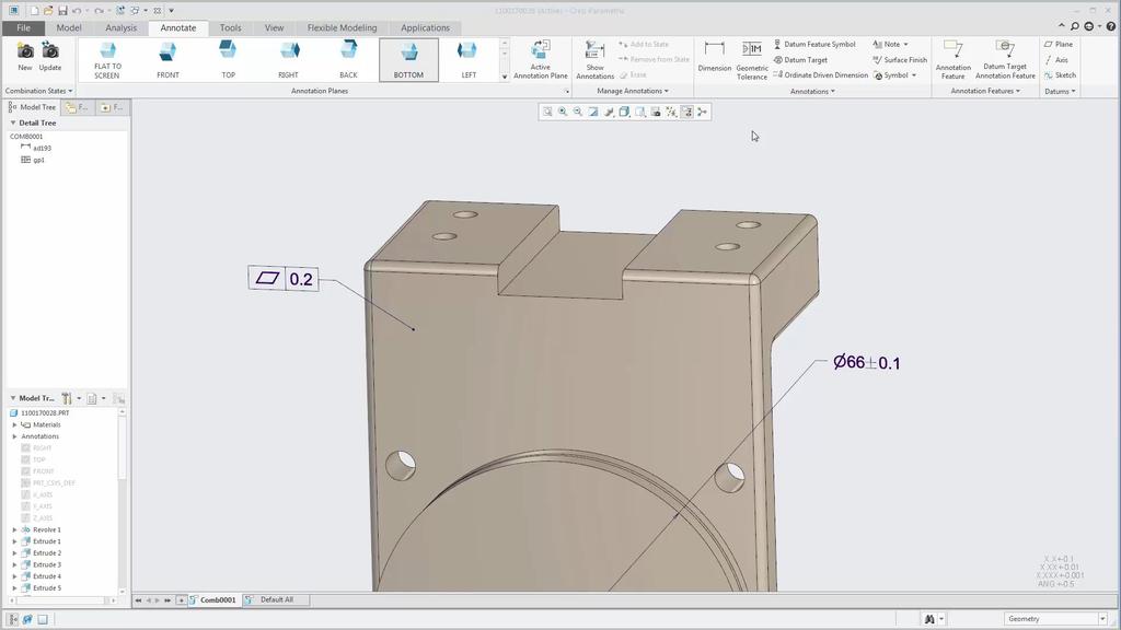
5 Creation and editing Immediate preview & placement options Contextual ribbon for editing properties Automatic naming Uses the next available name (A, B, C ) Check for proper name syntax DATUM FEATURE SYMBOL Semantic references Maintain reference to geometry No separate plane or axis needed Additional text Additional text placed adjacent to the symbol 5
6

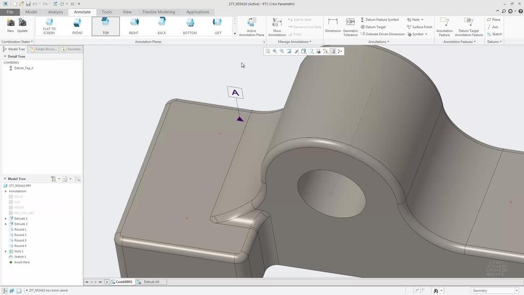
7 Creation and editing Immediate preview Contextual ribbon for editing properties Semantic reference to datum feature symbol Select datum feature symbol or type in text DATUM TARGET SYMBOL Built-in standard target areas Point, Circular, Rectangular, None Target area size related to dimension Standards support Outside dimension placement Movable datum target symbol Leader line enhancements 7
8

 Automatically created for GTOLs Place a coordinate system to")
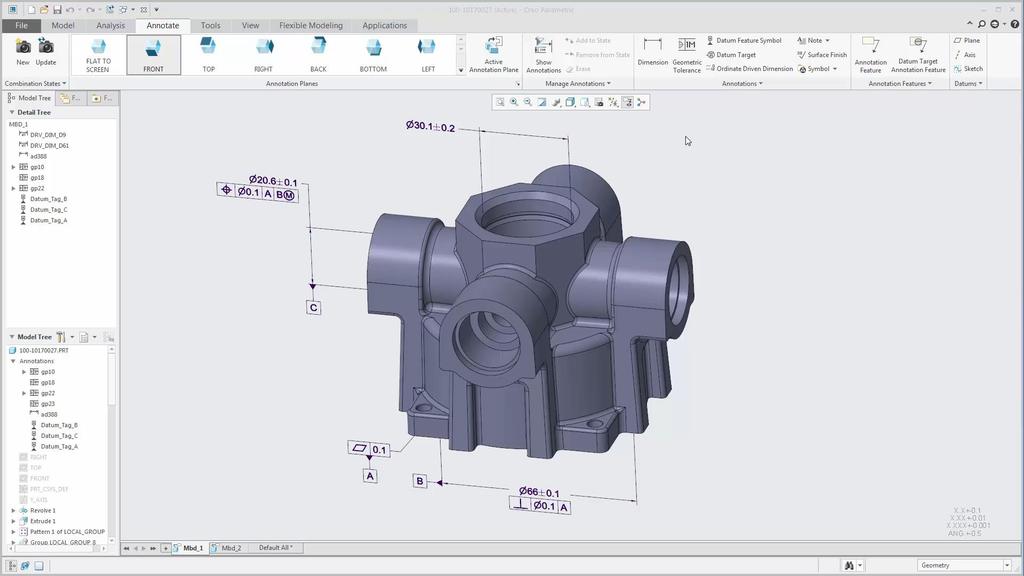
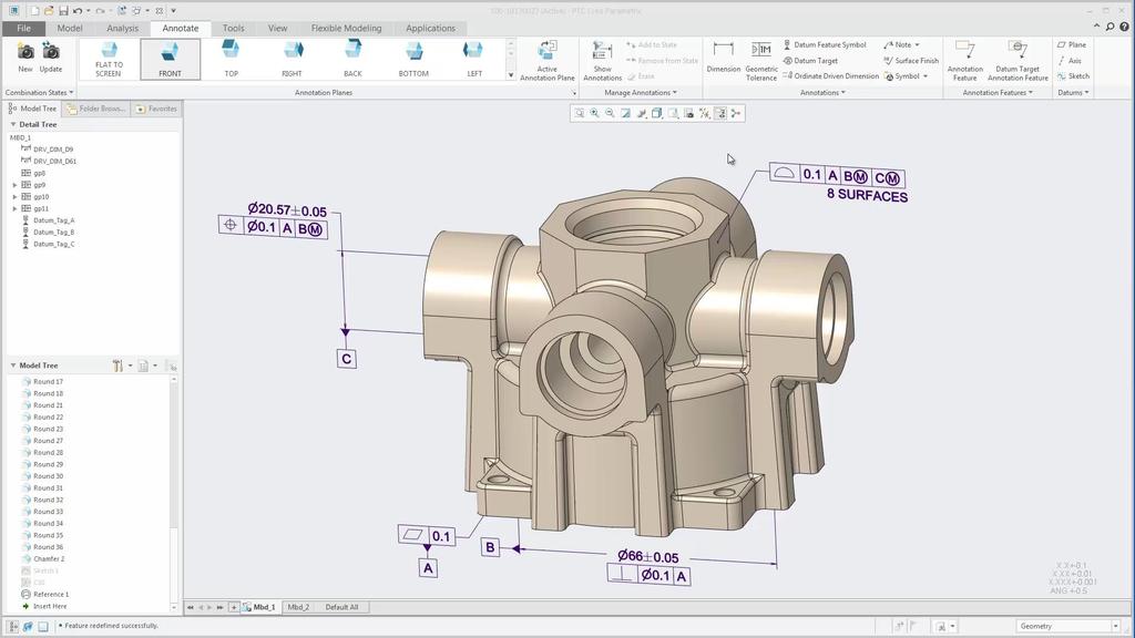
9 Creation and editing Immediate preview Contextual ribbon for editing properties GEOMETRIC TOLERANCE Text inputs for tolerance value and datum compartments Flexible typing of values and modifiers Updated text symbol palette Syntax checking Standards support ASME and ISO compliant Fully semantic references Integrated Datum Reference Frame (DRF) Automatically created for GTOLs Place a coordinate system to represent the DRF 9
10

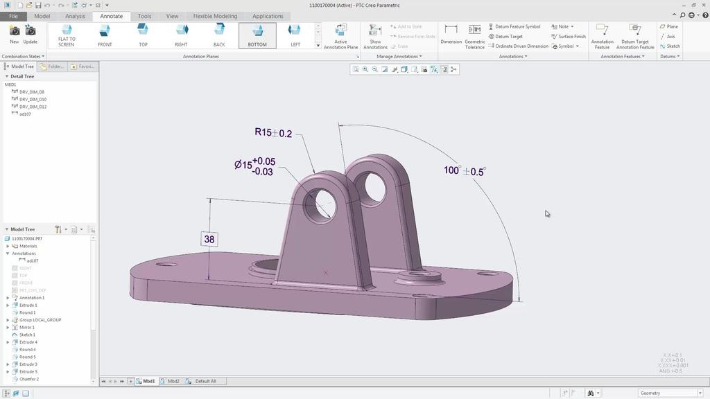
11 Creation and editing Immediate preview Contextual ribbon for editing properties Improved control of dimension orientation Dimensions between arcs/circles/cylinders Dimension placed on single linear entity DIMENSION Improved dimension text ASME and ISO text symbols Exclude prefix/suffix from basic dimension box Semantic references References collector Including DRIVING dimensions Dimension origin support 11
12


13 Standalone annotation behaviors Similar to annotation feature Notification center Improved appearance of coordinate systems Arrowheads on coordinate system axes Zoom-dependent option GENERAL ENHANCEMENTS Dynamic movement of annotations Individual selection and consistent dragging behavior ASME and ISO standard text and symbol fonts Option to avoid clipping annotations by cross-section Detail option: show_clipped_annotations 13


14 Appearance states Saved appearance in a combination state Visibility management Visibility of annotations and supplemental geometry using either layers or combination state COMBINATION STATE ENHANCEMENTS Publishing options Combination states to be published to Creo View Default combination state in Creo View 14
15
16

17 Print each combination state is on its own page Choose which combination states to print All, Current, Range COMBINATION STATE PRINTING Define a drawing format to be applied to the print Set a default format by configuration option 17
18
19 Model Based Definition (MBD) AGENDA GD&T Advisor Questions? 19

20 FAST, EASY, ACCURATE GD&T CREATION CREATION Feature-centric workflow guides the user Fast creation of annotations GD&T ADVISOR OVERVIEW VALIDATION Complies with ASME and ISO standards Fully constrains the model geometry EDUCATION Extensive help content Advisor messages provide feedback on status of the GD&T applied to the model 20


21 FUNCTIONAL FEATURE-CENTRIC GD&T Tolerance (Functional) Feature: Not a Creo modeling feature Geometric element classified by function GD&T ADVISOR WORKFLOW Workflow: Define the tolerance feature Determine tolerance scheme Determine tolerance values GD&T Advisor creates annotations Guidance Provided: Filtered UI Recommended options Not-permissible options Advisor Tree Errors and warnings Color-coding Visual feedback on completeness of tolerance definition 21
22 GD&T ADVISOR NEW IN CREO 4.0 CREO 4.0 ENHANCEMENTS Updated licensing and packaging New license extension sold by PTC Developed by Sigmetrix No installation required Updated standards rulesets ASME Y and associated standards ISO and associated standards Improved Creo integration Accessible from Applications tab Top-level ribbon based UI Fully semantic GD&T definition Streamlined model tree No longer creating GDT_ADVISOR group and associated Annotation Features 22
23
24 Model Based Definition (MBD) AGENDA GD&T Advisor Questions? 24
25
GETTING YOUR DIGITAL HOUSE IN ORDER
 GETTING YOUR DIGITAL HOUSE IN ORDER STREAMLINING THE MBD AND DETAILING PROCESS WITH CREO Martin Neumüller Creo Product Management PTC Eindhoven, 2017 AGENDA 1. MBD opportunities and challenges 2. Creo
Model-Based Definition using Creo Parametric and GD&T Advisor
 Model-Based Definition using Creo Parametric and GD&T Advisor Ted Anderson Product Line Manager Sigmetrix, LLC Model-Based Definition What is it? Why Model-Based Definition? What tools are required to
Creo Parametric 2.0: Introduction to Solid Modeling. Creo Parametric 2.0: Introduction to Solid Modeling
 Creo Parametric 2.0: Introduction to Solid Modeling 1 2 Part 1 Class Files... xiii Chapter 1 Introduction to Creo Parametric... 1-1 1.1 Solid Modeling... 1-4 1.2 Creo Parametric Fundamentals... 1-6 Feature-Based...
NIST MBE PMI Validation & Conformance Testing CTC Model Verification Results February 2015
 YOUR CENTRAL SOURCE FOR DATA EXCHANGE NIST MBE PMI Validation & Conformance Testing CTC Model Verification Results February 2015 Doug Cheney CAD Validation Specialist ITI TranscenData Doug.Cheney@TranscenData.com
Legacy Migration Extension (LMX) Legacy Drawing Associator (LDA) Annotation Convertor (AC) Assembly Configuration Collapse (ACC) December 2011 Rev G
 Legacy Drawing Associator (LDA) Annotation Convertor (AC) Assembly Configuration Collapse (ACC) December 2011 Rev G") Legacy Migration Extension (LMX) Legacy Drawing Associator (LDA) Annotation Convertor (AC) Assembly Configuration Collapse (ACC) December 2011 Rev G Agenda Introduction to Legacy Migration Extensions (LMX)
Legacy Migration Extension (LMX) Legacy Drawing Associator (LDA) Annotation Convertor (AC) Assembly Configuration Collapse (ACC) December 2011 Rev G Agenda Introduction to Legacy Migration Extensions (LMX)
Creo Parametric 4.0 Basic Design
 Creo Parametric 4.0 Basic Design Contents Table of Contents Introduction...1 Objective of This Textbook...1 Textbook Outline...2 Textbook Conventions...3 Exercise Files...3 System Configuration...4 Notes
Mechanical Design. CATIA - 3D Functional Tolerancing and Annotations 2 (FTA) CATIA V5R20
 CATIA V5R20") Mechanical Design CATIA - 3D Functional Tolerancing and Annotations 2 (FTA) CATIA V5R20 Mechanical Design CATIA - 3D Functional Tolerancing and Annotations Define and manage tolerance specifications and
Mechanical Design CATIA - 3D Functional Tolerancing and Annotations 2 (FTA) CATIA V5R20 Mechanical Design CATIA - 3D Functional Tolerancing and Annotations Define and manage tolerance specifications and
Lesson 16 Helical Sweeps and Annotations
 Lesson 16 Helical Sweeps and Annotations Figure 16.1 Helical Compression Spring Drawing OBJECTIVES Create a helical compression spring with a Helical Sweep Use sweeps to create hooks on extension springs
Geometry Controls and Report
 Geometry Controls and Report 2014 InnovMetric Software Inc. All rights reserved. Reproduction in part or in whole in any way without permission from InnovMetric Software is strictly prohibited except for
GD&T Encoding and Decoding with SpaceClaim
 GD&T Encoding and Decoding with SpaceClaim Dave Zwier Senior Technical Writer SpaceClaim GPDIS_2014.ppt 1 Biography Draftsman aerospace industry 1978-1980 B.S. Material Science Michigan State University
Functional Tolerancing and Annotations
 Functional Tolerancing and Annotations Preface Getting Started Basic Tasks Advanced Tasks Workbench Description Customizing Glossary Index Dassault Systèmes 1994-2000. All rights reserved. Preface CATIA
Introduction to Creo Parametric 2.0
 Introduction to Creo Parametric 2.0 Overview Course Code Course Length TRN-3902-T 5 Days In this course, you will learn core modeling skills and quickly become proficient with Creo Parametric 2.0. Topics
PolyWorks Inspector Standard. 3 Day Course
 PolyWorks Inspector Standard INTRODUCTION TO POLYWORKS Workspace Manager Basic Options File and Project Structures PolyWorks License Manager INTRODUCTION TO POLYWORKS INSPECTOR User Interface Basic Options
MODELING FOR THE END GAME > USABLE PARTS
 MODELING FOR THE END GAME > USABLE PARTS Mark Nielsen TechAzul 310-729-6275 liveworx.com # L I V E W O R X MARK NIELSEN Founder TechAzul BS & MS Mechanical Engineering, University of California, Berkeley
1: INTRODUCTION TO AUTOCAD
 AutoCAD syllabus 1: INTRODUCTION TO AUTOCAD Starting AutoCAD AutoCAD Screen Components Drawing Area Command Window Navigation bar Status bar Invoking Commands in AutoCAD Keyboard Ribbon Application Menu
Creo Parametric Primer
 Creo Parametric Primer Creo Parametric Primer Education Editions 2 C2-SE-L1-004-1.0 Written by Tim Brotherhood and Adam Haas Conditions of use Acknowledgements Feedback tbrotherhood@ptc.com Product code
Course Summary. CLASSROOM: On-site Instructor-led Education WEBINAR: Instructor-led On-line Training ON-DEMAND: Virtual Self-Paced Learning
 Course Summary CLASSROOM: On-site Instructor-led Education WEBINAR: Instructor-led On-line Training ON-DEMAND: Virtual Self-Paced Learning NO. COURSE NAME CLASSROOM* WEBINAR ON-DEMAND MBD/MBE EDUCATION
Getting to the end game with QIF: Useable Parts. Mark Nielsen TechAzul
 Getting to the end game with QIF: Useable Parts Mark Nielsen TechAzul 310-729-6275 mark@techazul.com Mark Nielsen Founder TechAzul Masters of Science in Mechanical Engineering, University of California,
User Guide V10 SP1 Addendum
 Alibre Design User Guide V10 SP1 Addendum Copyrights Information in this document is subject to change without notice. The software described in this document is furnished under a license agreement or
Sheet Metal Punch ifeatures
 Lesson 5 Sheet Metal Punch ifeatures Overview This lesson describes punch ifeatures and their use in sheet metal parts. You use punch ifeatures to simplify the creation of common and specialty cut and
What s New In SA CHAPTER
 What s New In SA CHAPTER 1 One of the advantages of SpatialAnalyzer is that development occurs at a brisk pace. New feature requests, bug fixes, and changes are implemented quickly, giving you the opportunity
Welcome to Solid Edge University
 #SEU15 Welcome to Solid Edge University Realize innovation. State-of-the-Art Drafting, Made Even Better Investing in What You Need General Workflow Dimension Enhancements Annotation Enhancements Page 2
Autodesk Advance Steel. Drawing Style Manager s guide
 Autodesk Advance Steel Drawing Style Manager s guide TABLE OF CONTENTS Chapter 1 Introduction... 5 Details and Detail Views... 6 Drawing Styles... 6 Drawing Style Manager... 8 Accessing the Drawing Style
Parametric Modeling with Creo Parametric 2.0
 Parametric Modeling with Creo Parametric 2.0 An Introduction to Creo Parametric 2.0 Randy H. Shih SDC PUBLICATIONS Schroff Development Corporation Better Textbooks. Lower Prices. www.sdcpublications.com
Starting a 3D Modeling Part File
 1 How to Create a 3D Model and Corresponding 2D Drawing with Dimensions, GDT (Geometric Dimensioning and Tolerance) Symbols and Title Block in SolidWorks 2013-2014 By Edward Locke This tutorial will introduce
Lesson 4 Holes and Rounds
 Lesson 4 Holes and Rounds 111 Figure 4.1 Breaker OBJECTIVES Sketch arcs in sections Create a straight hole through a part Complete a Sketched hole Understand the Hole Tool Use Info to extract information
Creo: Hole, Fillet, and Round Layout/Dimension Tutorial. By: Matthew Jourden Brighton High School
 Creo: Hole, Fillet, and Round Layout/Dimension Tutorial Layout of a Part with Holes 1. Open a blank drawing with your border and title block By: Matthew Jourden Brighton High School 2. Place the front,
Software Development & Education Center NX 8.5 (CAD CAM CAE)
") Software Development & Education Center NX 8.5 (CAD CAM CAE) Detailed Curriculum Overview Intended Audience Course Objectives Prerequisites How to Use This Course Class Standards Part File Naming Seed
Software Development & Education Center NX 8.5 (CAD CAM CAE) Detailed Curriculum Overview Intended Audience Course Objectives Prerequisites How to Use This Course Class Standards Part File Naming Seed
Custom Pillow Block Design Protrusion, Cut, Round, Draft (Review) Drawing (Review) Inheritance Feature (New) Creo 2.0
 Drawing (Review) Inheritance Feature (New) Creo 2.0") Custom Pillow Block Design Protrusion, Cut, Round, Draft (Review) Drawing (Review) Inheritance Feature (New) Creo 2.0 Rotatable pdf files: Casting Machining Grease Fitting Boss The general design of the
Custom Pillow Block Design Protrusion, Cut, Round, Draft (Review) Drawing (Review) Inheritance Feature (New) Creo 2.0 Rotatable pdf files: Casting Machining Grease Fitting Boss The general design of the
GEOMETRIC DIMENSIONING AND TOLERANCING (GD&T)
") GEOMETRIC DIMENSIONING AND TOLERANCING (GD&T) Based on ASME Y14.5M-1994 Standard Duration : 4 days Time : 9:00am 5:00pm Methodology : Instructor led Presentation, exercises and discussion Target : Individuals
GEOMETRIC DIMENSIONING AND TOLERANCING (GD&T) Based on ASME Y14.5M-1994 Standard Duration : 4 days Time : 9:00am 5:00pm Methodology : Instructor led Presentation, exercises and discussion Target : Individuals
Creo Parametric Primer
 PTC Creo Parametric - Primer Student and Academic Editions 02 Helpful hints are enclosed in red brackets or round bubbles like this one! Creo Parametric Primer THIS VERSION OF THE CREO PRIMER HAS BEEN
Alibre Vault Integration Automatic Check-in Prompt Sheet Metal Lofted Flanges & Assembly Constraints Sheet Metal Parameters
 1 TABLE OF CONTENTS General User Interface... 5 User Interaction Consistency... 5 Ctrl and Shift Behaviors... 5 Right-Click Behavior... 5 Dragging the Dog Bone... 6 Apply Button Added to Dialogs... 6 Missing
HOW TO REVIEW A CETOL 6σ ANALYSIS Presented by Dan Lange, Manager - Services
 HOW TO REVIEW A CETOL 6σ ANALYSIS Presented by Dan Lange, Manager - Services Abstract Reviewing a CETOL 6σ analysis requires a comprehensive understanding of the assembly being studied and the capabilities
EN1740 Computer Aided Visualization and Design Spring /16/2012 Brian C. P. Burke
 EN1740 Computer Aided Visualization and Design Spring 2012 2/16/2012 Brian C. P. Burke Last Time: Measuring within Pro/E 2D representation Orthographic projection 3 rd Angle vs. 1 st Angle Creating engineering
CADValidator: A Critical Aid for the Model-Based Enterprise
 CADValidator: A Critical Aid for the Model-Based Enterprise Abstract Learn the importance of validation for deployment of model-based engineering practices. In addition, understand what functionality is
Product and Manufacturing Information (PMI)
") Product and Manufacturing Information (PMI) 1 Yadav Virendrasingh Sureshnarayan, 2 R.K.Agrawal 1 Student of ME in Product Design and Development,YTCEM -Bhivpuri road-karjat, Maharastra 2 HOD Mechanical
Product and Manufacturing Information (PMI) 1 Yadav Virendrasingh Sureshnarayan, 2 R.K.Agrawal 1 Student of ME in Product Design and Development,YTCEM -Bhivpuri road-karjat, Maharastra 2 HOD Mechanical
Lesson 4 Extrusions OBJECTIVES. Extrusions
 Lesson 4 Extrusions Figure 4.1 Clamp OBJECTIVES Create a feature using an Extruded protrusion Understand Setup and Environment settings Define and set a Material type Create and use Datum features Sketch
GEN20604 Intelligent AutoCAD Model Documentation Made Easy
 GEN20604 Intelligent AutoCAD Model Documentation Made Easy David Cohn 4D Technologies Learning Objectives Learn how to create base views and projected views from 3D models Learn how to create and control
GEOMETRIC DIMENSIONING AND TOLERANCING (GD&T) Based on ASME Y14.5M-1994 Standard
 Based on ASME Y14.5M-1994 Standard") GEOMETRIC DIMENSIONING AND TOLERANCING (GD&T) Based on ASME Y14.5M-1994 Standard Duration: 4 Days Training Course Content: Day 1: Tolerancing in Engineering Drawing (9:00am-10:00am) 1.0 Geometric Dimensioning
GEOMETRIC DIMENSIONING AND TOLERANCING (GD&T) Based on ASME Y14.5M-1994 Standard Duration: 4 Days Training Course Content: Day 1: Tolerancing in Engineering Drawing (9:00am-10:00am) 1.0 Geometric Dimensioning
Generative Drafting (ISO)
") CATIA Training Foils Generative Drafting (ISO) Version 5 Release 8 January 2002 EDU-CAT-E-GDRI-FF-V5R8 1 Table of Contents (1/2) 1. Introduction to Generative Drafting Generative Drafting Workbench Presentation
CATIA Training Foils Generative Drafting (ISO) Version 5 Release 8 January 2002 EDU-CAT-E-GDRI-FF-V5R8 1 Table of Contents (1/2) 1. Introduction to Generative Drafting Generative Drafting Workbench Presentation
Drawing and Detailing with SolidWorks 2014
 r n fo io n at io c at tifi ar er ep c pr WT es D R u d Pcl In C S W e th W E N Drawing and Detailing with SolidWorks 2014 Referencing the ASME Y14 Engineering Drawing and Related Documentation Practices
Technical What s New. AutoCAD. Mechanical 2011
 AutoCAD Mechanical 2011 Welcome to AutoCAD Mechanical 2011 Contents Content Library...3 General Enhancements...3 Localization...3 Improved International Standards...3 Update Content Selectively...3 Part
Estimated Time Required to Complete: 45 minutes
 Estimated Time Required to Complete: 45 minutes This is the first in a series of incremental skill building exercises which explore sheet metal punch ifeatures. Subsequent exercises will address: placing
Product and Manufacturing Information(PMI)
") Product and Manufacturing Information(PMI) Ravi Krishnan V 1 Post Graduate Student Department of Mechanical Engineering Veermata Jijabai Technological Institute Mumbai, India ravi.krishnan30@gmail.com
Product and Manufacturing Information(PMI) Ravi Krishnan V 1 Post Graduate Student Department of Mechanical Engineering Veermata Jijabai Technological Institute Mumbai, India ravi.krishnan30@gmail.com
Chapter 5 Sectional Views
 Chapter 5 Sectional Views There are a number of different types of sectional views that can be drawn. A few of the more common ones are: full sections, half sections, broken sections, rotated or revolved
Using open CAD formats to bridge the gap between today s and tomorrow s standards CAPVIDIA Tomasz Luniewski
 Using open CAD formats to bridge the gap between today s and tomorrow s standards CAPVIDIA Tomasz Luniewski GPDIS_2012.ppt 1 CAPVIDIA Founded in 1994 (Belgium, Russia, USA, China, Japan) Development of
ISO 1101 Geometrical product specifications (GPS) Geometrical tolerancing Tolerances of form, orientation, location and run-out
 Geometrical tolerancing Tolerances of form, orientation, location and run-out") INTERNATIONAL STANDARD ISO 1101 Third edition 2012-04-15 Geometrical product specifications (GPS) Geometrical tolerancing Tolerances of form, orientation, location and run-out Spécification géométrique
INTERNATIONAL STANDARD ISO 1101 Third edition 2012-04-15 Geometrical product specifications (GPS) Geometrical tolerancing Tolerances of form, orientation, location and run-out Spécification géométrique
Shaft Hanger - SolidWorks
 ME-430 INTRODUCTION TO COMPUTER AIDED DESIGN Shaft Hanger - SolidWorks BY: DR. HERLI SURJANHATA ASSIGNMENT Submit TWO isometric views of the Shaft Hanger with your report, 1. Shaded view of the trimetric
Getting Started. Before You Begin, make sure you customized the following settings:
 Getting Started Getting Started Before getting into the detailed instructions for using Generative Drafting, the following tutorial aims at giving you a feel of what you can do with the product. It provides
Geometric Dimensioning and Tolerancing
 Geometric Dimensioning and Tolerancing (Known as GDT) What is GDT Helps ensure interchangeability of parts. Use is dictated by function and relationship of the part feature. It does not take the place
Creo Parametric Primer
 Creo Parametric Primer Creo Parametric Primer Education Editions C1-SE-L1-004-1.0 Written by Tim Brotherhood and Adam Haas Conditions of use Acknowledgements Feedback tbrotherhood@ptc.com Product code
Comprehensive GD&T Evaluation Software for Manufacturing Quality Control
 Comprehensive GD&T Evaluation Software for Manufacturing Quality Control Model-Based Family of Software EVOLVE SmartProfile Comprehensive GD&T Evaluation Software for Manufacturing Quality Control Easy
What s New In SA CHAPTER
 What s New In SA CHAPTER 2 One of the advantages of SpatialAnalyzer is that development occurs at a brisk pace. New feature requests, bug fixes, and changes are implemented quickly, giving you the opportunity
Datum Tutorial Part: Cutter
 Datum Tutorial Part: Cutter Objective: Learn to apply Datums in different ways Directions 1. Datum Axis Creation a. First we need to create a center axis for the cutter b. Model Tab > Datum > Select Axis
ARCHICAD Introduction Tutorial
 Starting a New Project ARCHICAD Introduction Tutorial 1. Double-click the Archicad Icon from the desktop 2. Click on the Grey Warning/Information box when it appears on the screen. 3. Click on the Create
Introduction. Parametric Design
 Introduction This text guides you through parametric design using Creo Parametric. While using this text, you will create individual parts, assemblies, and drawings. Parametric can be defined as any set
Advance Steel. Drawing Style Manager s guide
 Advance Steel Drawing Style Manager s guide TABLE OF CONTENTS Chapter 1 Introduction...7 Details and Detail Views...8 Drawing Styles...8 Drawing Style Manager...9 Accessing the Drawing Style Manager...9
Mechanical Drawing. Unit 2 Study Guide for Chapters 6-10
 Mechanical Drawing Unit 2 Study Guide for Chapters 6-10 Chapter 6 Multiview Drawing Section 6.1 Understanding Orthographic Projection A. Technical Drawing: How can a technical drawing give more accurate
Getting Started. Chapter. Objectives
 Chapter 1 Getting Started Autodesk Inventor has a context-sensitive user interface that provides you with the tools relevant to the tasks being performed. A comprehensive online help and tutorial system
Mechanical Design CATIA - Interactive Drafting 1 (ID1) CATIA V5R20
 CATIA V5R20") Mechanical Design CATIA - Interactive Drafting 1 (ID1) CATIA V5R20 Mechanical Design CATIA - Interactive Drafting Address 2D design and drawing production requirements. Product overview Interactive Drafting
Mechanical Design CATIA - Interactive Drafting 1 (ID1) CATIA V5R20 Mechanical Design CATIA - Interactive Drafting Address 2D design and drawing production requirements. Product overview Interactive Drafting
Set your drafting standard and drawing preferences
 DRAFTING The Drafting application is designed to allow you to produce and maintain industry standard engineering drawings directly from the 3D model or assembly part. Drawings created in the Drafting application
Introduction to ISDX Interactive Surface Design Extension Creo 2.0. Level 7 Continued
 Introduction to ISDX Interactive Surface Design Extension Creo 2.0 Level 7 Continued Create or modify your config.pro (or edit and save a config.pro) such that the graphics driver is changed to opengl.
Autodesk Inventor 2016
 Parametric Modeling with Autodesk Inventor 2016 Randy H. Shih SDC PUBLICATIONS Better Textbooks. Lower Prices. www.sdcpublications.com Powered by TCPDF (www.tcpdf.org) Visit the following websites to learn
Mastering AutoCAD 2D
 Course description: Mastering AutoCAD 2D Design and shape the world around you with the powerful, flexible features found in AutoCAD software, one of the world s leading 2D design applications. With robust
Dimensioning. Subject Matters:
 Objectives: To define dimensioning. To recognise the different types of dimensions. To define and create a dimension style. To recognise the dimension toolbar and the dimensioning commands. To create dimensions
Generative Drafting Overview What's New Getting Started User Tasks
 Generative Drafting Overview Conventions What's New Getting Started Defining the Drawing Sheet Part Drawing Opening a Part Creating a Front View Creating a Projection View Creating a Section View Creating
Drawing and Detailing
 Drawing and Detailing with SolidWorks 2007 By David C. Planchard and Marie P. Planchard Referencing the ASME Y14 Engineering Drawing and Related Documentation Practices SDC PUBLICATIONS Schroff Development
Engineering Innovation Center Fabrication Shop Basic CAD Training
 Engineering Innovation Center Fabrication Shop Basic CAD Training Introduction The Engineering Innovation Center Fabrication Shop was established for support of undergraduate student course work. Every
IE11, Edge (current version), Chrome (current version), Firefox (current version)
, Chrome (current version), Firefox (current version)") Quick Start Guide DocuSign for SharePoint Online v3.4 Published: October 13, 2017 Overview DocuSign for SharePoint Online allows users to sign or send documents for signature from a SharePoint Online library.
Quick Start Guide DocuSign for SharePoint Online v3.4 Published: October 13, 2017 Overview DocuSign for SharePoint Online allows users to sign or send documents for signature from a SharePoint Online library.
To help understand the 3D annotations, the book includes a complete tutorial on SOLIDWORKS MBD
 To help understand the 3D annotations, the book includes a complete tutorial on SOLIDWORKS MBD Technical product documentation using ISO GPS - ASME GD&T standards FOREWORD Designers create perfect and
FOREWORD. Technical product documentation using ISO GPS - ASME GD&T standards
 Technical product documentation using ISO GPS - ASME GD&T standards FOREWORD Designers create perfect and ideal geometries through drawings or by means of Computer Aided Design systems, but unfortunately
ISO INTERNATIONAL STANDARD. Technical product documentation Digital product definition data practices
 INTERNATIONAL STANDARD ISO 16792 First edition 2006-12-15 Technical product documentation Digital product definition data practices Documentation technique de produits Données de définition d'un produit
Dimensioning. Dimensions: Are required on detail drawings. Provide the shape, size and location description: ASME Dimensioning Standards
 Dimensioning Dimensions: Are required on detail drawings. Provide the shape, size and location description: - Size dimensions - Location dimensions - Notes Local notes (specific notes) General notes ASME
Corridors. To create a corridor you must have an alignment (baseline), a profile (existing or proposed), and an assembly.
, a profile (existing or proposed), and an assembly.") Corridors To create a corridor you must have an alignment (baseline), a profile (existing or proposed), and an assembly. Alignments You have 2 choices in defining an alignment: (1) Alignments > Create
Corridors To create a corridor you must have an alignment (baseline), a profile (existing or proposed), and an assembly. Alignments You have 2 choices in defining an alignment: (1) Alignments > Create
Assembly Receiver/Hitch/Ball/Pin to use for CAD LAB 5A and 5B:
 MECH 130 CAD LAB 5 SPRING 2017 due Friday, April 21, 2016 at 4:30 PM All of LAB 5 s hardcopies will be working drawing layouts. Do not print out from the part file. We will be using the ME130DRAW drawing
Denmark Iceland Sweden Norway Germany
 Del 1: MBD Model Based Definitions Ny Hulkommando Sheet metal ilogic Del2: Performance Shared view Forbedret Direct Edit funktion Nyheder Inventor 2018.1 What s New Parts Model-Based Definition Support
Top Down Assembly Modeling Release Wildfire 2.0
 Top Down Assembly Modeling Release Wildfire 2.0 Note: Comprehensive Modeling Assignment This is a 30 point assignment as such takes the place of the final exam. Four Plate Mold Base, Inner Two Plates Begin
Geometric Boundaries
 Geometric Boundaries Interpretation and Application of Geometric Dimensioning and Tolerancing (Using the Customary Inch System) Based on ASME Y14.5M-1994 Written and Illustrated by Kelly L. Bramble Published
Published on Online Documentation for Altium Products (http://www.altium.com/documentation)
") Published on Online Documentation for Altium Products (http://www.altium.com/documentation) Home > Draftsman Enhancements A New Era for Documentation Modified by Jason Howie on Dec 4, 2017 The Altium Designer
Published on Online Documentation for Altium Products (http://www.altium.com/documentation) Home > Draftsman Enhancements A New Era for Documentation Modified by Jason Howie on Dec 4, 2017 The Altium Designer
Module 2.1, 2.2 Review. EF101 Analysis & Skills Module 2.3. Sketched Features and Operations. On-line Help Two Locations
 EF101 Analysis & Skills Module 2.3 Engineering Graphics Revolved Features Placed Features Work Features Module 2.1, 2.2 Review What are the three types of operations for adding features to the base feature?
Release Highlights for BluePrint-PCB Product Version 2.0.1
 Release Highlights for BluePrint-PCB Product Version 2.0.1 Introduction BluePrint Version 2.0.1 is a rolling release for BluePrint V2.0. BluePrint rolling releases are delivered as needed and allow us
1. Open the Feature Modeling demo part file on the EEIC website. Ask student about which constraints needed to Fully Define.
 BLUE boxed notes are intended as aids to the lecturer RED boxed notes are comments that the lecturer could make Control + Click HERE to view enlarged IMAGE and Construction Strategy he following set of
CREO.1 MODELING A BELT WHEEL
 CREO.1 MODELING A BELT WHEEL Figure 1: A belt wheel modeled in this exercise. Learning Targets In this exercise you will learn: Using symmetry when sketching Using pattern to copy features Using RMB when
Engineering Design with
 Engineering Design with SOLIDWORKS 2016 and Video Instruction A Step-by-Step Project Based Approach Utilizing 3D Solid Modeling David C. Planchard, CSWP, SOLIDWORKS Accredited Educator SDC PUBLICATIONS
Part Design Fundamentals
 Part Design Fundamentals 1 Course Presentation Objectives of the course In this course you will learn basic methods to create and modify solids features and parts Targeted audience New CATIA V5 Users 1
Sheet Metal OverviewChapter1:
 Sheet Metal OverviewChapter1: Chapter 1 This chapter describes the terminology, design methods, and fundamental tools used in the design of sheet metal parts. Building upon these foundational elements
GEOMETRICAL TOLERANCING
 GEOMETRICAL TOLERANCING Introduction In a typical engineering design and production environment, the designer of a part rarely follows the design to the shop floor, and consequently the only means of communication
Terms The definitions of 16 critical terms defined by the 2009 standard 1
 856 SALT LAKE COURT SAN JOSE, CA 95133 (408) 251 5329 Terms The definitions of 16 critical terms defined by the 2009 standard 1 The names and definitions of many GD&T terms have very specific meanings.
Challenger, Fendt, Massey Ferguson and Valtra,
 Overview AGCO, Your Agriculture Corporation, was founded in 1990. We offer a full product line of tractors, combines, hay tools, sprayers, forage, tillage equipment, implements and related replacement
Virtual components in assemblies
 Virtual components in assemblies Publication Number spse01690 Virtual components in assemblies Publication Number spse01690 Proprietary and restricted rights notice This software and related documentation
 http://blogs.solidworks.com/solidworksblog/2015/10/mbdimplementation-10-dos-and-10-donts-dont-hesitate-part-1.html Create MBE Vision Plan Identify Data Needs Assess PMI Consumption 3 DimXperts 2D Drawings
CETOL 6σ Tutorial. For Pro/Engineer and Creo Parametric. The table. CETOL 6σ / ProE. Page 1
 CETOL 6σ Tutorial For Pro/Engineer and Creo Parametric The table Page 1 The Table Description: This tutorial will show you the basic functionality of CETOL 6 Sigma. An analysis normally starts with a definition
What s New in SA SA Repeat Alignments
 What s New in SA SA 2012.12.06 Repeat Alignments To Repeat an Instrument s Alignment: Any instrument s alignment can now be repeated, making alignments as part of a repeatable process easier to set up.
An Introduction to Dimensioning Dimension Elements-
 An Introduction to Dimensioning A precise drawing plotted to scale often does not convey enough information for builders to construct your design. Usually you add annotation showing object measurements
Activity 1 Modeling a Plastic Part
 Activity 1 Modeling a Plastic Part In this activity, you will model a plastic part. When completed, your plastic part should look like the following two illustrations. While building this model, take time
Corridors To create a corridor you must have an alignment (baseline), a profile (existing or proposed), and an assembly.
, a profile (existing or proposed), and an assembly.") Corridors 2018-2019 To create a corridor you must have an alignment (baseline), a profile (existing or proposed), and an assembly. Alignments You have 2 choices in defining an alignment from scratch: (1)
Corridors 2018-2019 To create a corridor you must have an alignment (baseline), a profile (existing or proposed), and an assembly. Alignments You have 2 choices in defining an alignment from scratch: (1)
PTC Technical Specialists E-Newsletter Date: April 1, 2006
 PTC Technical Specialists E-Newsletter Date: April 1, 2006 PTC Product Focus: A) What s New in Detail Drawings for Wildfire 3.0 Tips of the Month: B) Windchill Supplier Management Solution A) Tricks with
A Conceptual Data Model of Datum Systems
 [J. Res. Natl. Inst. Stand. Technol. 104, 349 (1999)] A Conceptual Data Model of Datum Systems Volume 104 Number 4 July August 1999 Michael R. McCaleb National Institute of Standards and Technology, Gaithersburg,
Precision for People. 3D Multisensor Metrology Software. Precision for People
 Precision for People 3D Multisensor Metrology Software Precision for People Put 30 Years of Multisensor Experience to Work for You ZONE3 metrology software puts the power of OGP s 30 years of multisensor
Certified SOLIDWORKS Professional Advanced Preparation Materials
 Includes Preparation for Five Advanced Certification Exams Certified SOLIDWORKS Professional Advanced Preparation Materials Sheet Metal, Weldments, Surfacing, Mold Tools and Drawing Tools SOLIDWORKS 2016