Model-Based Definition using Creo Parametric and GD&T Advisor
|
|
|
- Mariah Perkins
- 6 years ago
- Views:
Transcription


1 Model-Based Definition using Creo Parametric and GD&T Advisor Ted Anderson Product Line Manager Sigmetrix, LLC
2 Model-Based Definition What is it? Why Model-Based Definition? What tools are required to define the model? What are the down-stream benefits?
3 Modeling Paradigms Master 2D Drawing Drawingbased Model- Centric 3D CAD Model Master 2D Drawing Model-Based Definition Master 3D CAD Model
4 Definitions MBD: Model Based Definition; i.e., what a design engineer creates within CAD software to express design intent MBE: Model Based Enterprise; i.e., an organization that reuses model-based definition for downstream applications and processes
5 Model-Based Environment 3D Drawing Other? Tolerance Analysis Model Automated Inspection Cost Estimation

6 What is Model-Based Definition? Also known as: Digital Product Definition Standards defined in: ASME Y ISO 16792:2006
7 What is the model? Definitions (from ASME Y ) Model a combination of design model, annotation and attributes that describes the product Design model the portion of the data set that contains model and supplemental geometry Annotation dimensions, tolerances, notes, text, or symbols visible without any manual or external manipulation Attribute a dimension, tolerance, note, text or symbol required to complete the product definition or feature of the product that is not visible but available upon interrogation of the model
8 A model includes more than geometry! Model Visible dimensions, tolerances, geometric tolerances, and notes Annotations Design Model Attributes Model geometry Parameters, material properties, etc.


9 A model includes more than geometry! Design Model + Attributes + Annotations = Model
10 Why Model-Based Definition? Establishes clear design authority ("the model is the master") Enables elimination of redundant tasks and information Enables reuse of model definition data in downstream applications and processes throughout the manufacturing enterprise
11 When will all of this happen? Enabling technology is available now Many downstream applications are available now Many companies are investigating the tools and processes now Some leading-edge companies have already begun MBE implementation DoD is pushing MBE
12 MBD and Department of Defense DoD agencies (NIST, OSD, DLA, etc.) are working to eliminate drawings from the defense supply chain NIST released MIL-STD Rev A in Feb 2013: New 3D definition for Technical Data Package Sets contract requirements for delivering technical data MBD is a contract requirement for new programs PDF (3D PDF) is preferred delivery format

 Slide")
13 DoD is shifting to Model Based Enterprise Eliminate need for 2D Drawings throughout the DOD & Supply Chain 3D Technical Data Packages: Complete Product Definition 3D Animated Work Instructions: Complete Process Definition 3D Inspection Documents: Advanced Inspection Procedures 3D RFP/RFQ Low-Cost Procurement Dramatically reduce costs for procurement throughout the DOD supply chain Eliminate dependency on proprietary CAD Formats Deploy complete Product Definition within lightweight 3D PDF TDPs Deploy complete Manufacturing Best Practices within animated 3D PDF MBEs Allow Product and Manufacturing data to be Freely deployed on standard platforms (FREE Adobe Reader & FREE HTML5 Browsers) Slide courtesy of ANARK

14 Why the paradigm shift? Lower Cost A DLA survey showed that if a modern tech data package was provided to the supplier, it would help reduce the procurement cost of a part by almost 27% This will reduce DOD procurement costs by 27% The survey noted that suppliers would be able to reduce the cost of quoting, which accounts for 8% of the bid This will reduce supplier costs by 8% Faster Delivery The DLA survey indicated that almost 19% of supplier scrap and rework was due to poor TDP quality This will reduce scrap and rework costs by 19% 3D TDP will help streamline the creation of process plans and decrease the chances for manufacturing errors Suppliers will be able to use model data to rapidly create instructions for production operations and inspection Focused on the War Fighter Slide courtesy of ANARK

15 MBD in Creo Parametric 2.0 Annotation tools in Creo 2.0: Apply Geometric Tolerances Specify tolerances for dimensions Create 3D notes
16 GD&T in Creo Creo tools for creating geometric tolerance annotations are rudimentary No standards-based rules No automatic checking No guidance for the user Very mouse-click intensive and prone to error The tools available for creating GD&T in Creo are not sufficient for an model-based enterprise


17 GD&T Advisor An embedded Creo application Creates native Creo GD&T annotations Uses an intuitive GD&T dashboard, guaranteeing proper application of GD&T In process help to guide and educate the user Feature-centric view of GD&T Wizard-like dashboard guides the user in the correct application of GD&T Informative advisor messages to guide the user through the process Create native Creo annotations to maximize reusability
18 GD&T Advisor Benefits Supports MBD Creates annotations in the model so they can be reused downstream Fast and efficient About %75 fewer mouse-clicks required to create annotations (compared to native Creo tools) Correct and complete GD&T on the model Rules-based filters, annotation placement and validation Promotes GD&T knowledge and understanding
19 GD&T Advisor Available for: ASME Y14.5M-1994 ISO 1101:2004 and related standards A critical part of the model-based enterprise


20 MBD in Creo Parametric 2.0 Combination States A tool for managing views and annotations Defines a 3D view that is analogous to a 2D drawing view

21 MBD in Creo Parametric 2.0 Annotate Ribbon Provides functionality for defining combination states and annotations Add or delete Combination States Add annotations on specified annotation plane Manage annotations similar to the way they can be managed in a drawing

22 MBD in Creo Parametric 2.0 3D Detail options Control the appearance of 3D annotations Similar to drawing detail options for controlling drawing appearance
23 MBD and GD&T In order to fully leverage the advantages of MBD: GD&T must be applied to the model (rather than defined in a 2D drawing) GD&T must be applied in accordance with the specified tolerancing standards GD&T must faithfully represent the design requirements GD&T must by correct and complete
24 Defining the model Creo Parametric 2.0 GD&T Advisor
25 Model-Based Environment 3D Drawing Other? Tolerance Analysis Model Automated Inspection Cost Estimation
26 Downstream uses for MBD 3D Drawing Other? Tolerance Analysis Model Automated Inspection Cost Estimation
27 Why do we use 2D drawings? Drawings have been the "visual language" of engineering for hundreds of years Drawings provide critical manufacturing information like datums, dimensions, tolerances, etc. Until recently it hasn't been possible to express this information within a 3D environment Drawings are "easier to deal with" vs. 3D CAD models 2D TIFFs and PDFs, are smaller, easier to send, and can be opened without an expensive 3D CAD software license "Everyone" knows how to use them (2D drawings) 2D drawings (printed or electronic) can easily be redlined, reviewed, marked up, etc.
28 Why should we eliminate 2D drawings? Model vs. Drawing: Which is the master? DoD: 60% of supplier data where model and drawing don t agree Time and effort to create and maintain drawings 30% total product development budget Response times to/from suppliers much faster 50% reduction in supplier response time in MBE There are better solutions for communicating design intent...and eliminating ambiguities, scrap, rework, etc. Conclusions from NIST/US Army Supplier Survey:
29 3D Drawings Available in many formats 3D PDF Viewable in Adobe reader HTML/WebGL Viewable in modern browsers (plug-in required) JT STEP AP214 Proprietary formats (e.g., Creo View)
30 3D Drawings - Advantages Automatic creation from model Unambiguous Non-redundant data and effort Interactive query and measure tools, etc.

31 Annotation Query GD&T that has been applied with GD&T Advisor in Creo is properly associated with the applicable surfaces (in accordance with ASME Y )

32 3D PDF Example
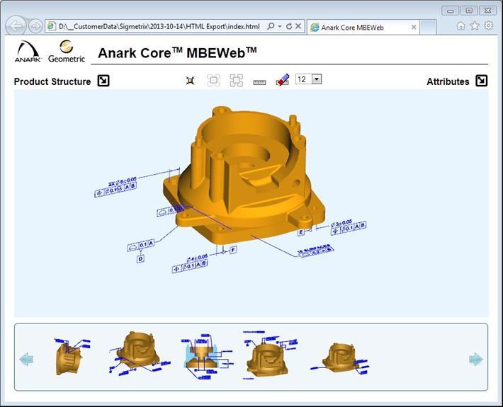
33 HTML/WebGL Example
34 Downstream uses for MBD 3D Drawing Other? Tolerance Analysis Model Automated Inspection Cost Estimation

35 Tolerance Analysis CETOL 6 v8.3 Import feature annotations from the CAD model Imported dimensions and gtols are linked to the related CAD annotation Linked objects automatically update (eliminates data entry and related errors)
36 Futures: CETOL 6 v9 Will read GD&T Advisor data Automate the tolerance analysis process at the part level Completely eliminates redundant effort for defining dimensions and tolerances
37 Downstream uses for MBD 3D Drawing Other? Tolerance Analysis Model Automated Inspection Cost Estimation

38 Cost Estimation MBD models include most of the data that affects part cost: Model geometry Material & other attributes GD&T & dimensional tolerances Downstream applications are available that provide accurate cost predictions
39 Downstream uses for MBD 3D Drawing Other? Tolerance Analysis Model Automated Inspection Cost Estimation
 with the")
40 Automated Inspection GD&T defines quality requirements Inspection confirms whether requirements are met Downstream applications are available that integrate the CAD data (geometry and annotation data) with the inspection process
41 A complete model is required! 3D Drawing Other? Tolerance Analysis Model Automated Inspection Cost Estimation
42 Conclusions Model-Based Definition can be achieved with Creo Parametric 2.0 and GD&T Advisor Eliminating drawings in favor of MBD can result in significant savings There are a multitude of downstream uses for MBD
GETTING YOUR DIGITAL HOUSE IN ORDER
 GETTING YOUR DIGITAL HOUSE IN ORDER STREAMLINING THE MBD AND DETAILING PROCESS WITH CREO Martin Neumüller Creo Product Management PTC Eindhoven, 2017 AGENDA 1. MBD opportunities and challenges 2. Creo
CREO 4.0: MODEL BASED DEFINITION (MBD)
") CREO 4.0: MODEL BASED DEFINITION (MBD) Raphael Nascimento Product Manager PTC Creo 17 November, 2016 PTC Forum Europe Stuttgart, Germany Model Based Definition (MBD) AGENDA GD&T Advisor Questions? 2 Model
CREO 4.0: MODEL BASED DEFINITION (MBD) Raphael Nascimento Product Manager PTC Creo 17 November, 2016 PTC Forum Europe Stuttgart, Germany Model Based Definition (MBD) AGENDA GD&T Advisor Questions? 2 Model
CADValidator: A Critical Aid for the Model-Based Enterprise
 CADValidator: A Critical Aid for the Model-Based Enterprise Abstract Learn the importance of validation for deployment of model-based engineering practices. In addition, understand what functionality is
Course Summary. CLASSROOM: On-site Instructor-led Education WEBINAR: Instructor-led On-line Training ON-DEMAND: Virtual Self-Paced Learning
 Course Summary CLASSROOM: On-site Instructor-led Education WEBINAR: Instructor-led On-line Training ON-DEMAND: Virtual Self-Paced Learning NO. COURSE NAME CLASSROOM* WEBINAR ON-DEMAND MBD/MBE EDUCATION
How PMI and Data Modeling Standards Affect Successful Implementation of 3D MBD/MBE
 How PMI and Data Modeling Standards Affect Successful Implementation of 3D MBD/MBE Understanding and Managing Risk in Implementation and Transition Bryan R. Fischer Advanced Dimensional Management LLC
Leverage 3D Master. Improve Cost and Quality throughout the Product Development Process
 Leverage 3D Master Improve Cost and Quality throughout the Product Development Process Introduction With today s ongoing global pressures, organizations need to drive innovation and be first to market
The Importance of a Technical Data Package to Support 3D MBE. Glen Voglesong Faurecia Rahim Alsaffar Johnson Controls
 The Importance of a Technical Data Package to Support 3D MBE Glen Voglesong Faurecia Rahim Alsaffar Johnson Controls Johnson Controls Automotive Agenda Introduction Information & Technology What s a TDP?
Model Based Definition The future mode of product TPD
 Model Based Definition The future mode of product TPD 11-10- 2018 Leo Broers Project Manager ASML QC DE CSI ASML organization Slide 2 Lithography is the critical tool for producing chips All of the world
MODELING FOR THE END GAME > USABLE PARTS
 MODELING FOR THE END GAME > USABLE PARTS Mark Nielsen TechAzul 310-729-6275 liveworx.com # L I V E W O R X MARK NIELSEN Founder TechAzul BS & MS Mechanical Engineering, University of California, Berkeley
Product and Manufacturing Information(PMI)
") Product and Manufacturing Information(PMI) Ravi Krishnan V 1 Post Graduate Student Department of Mechanical Engineering Veermata Jijabai Technological Institute Mumbai, India ravi.krishnan30@gmail.com
Product and Manufacturing Information(PMI) Ravi Krishnan V 1 Post Graduate Student Department of Mechanical Engineering Veermata Jijabai Technological Institute Mumbai, India ravi.krishnan30@gmail.com
The How-to Guide for Adopting Model Based Definition (MBD) Michelle Boucher Vice President Tech-Clarity
 Michelle Boucher Vice President Tech-Clarity") 1 The How-to Guide for Adopting Model Based Definition (MBD) Michelle Boucher Vice President Tech-Clarity 2 The Importance of Engineering Investments What strategies will your company use to improve profitability?
1 The How-to Guide for Adopting Model Based Definition (MBD) Michelle Boucher Vice President Tech-Clarity 2 The Importance of Engineering Investments What strategies will your company use to improve profitability?
Product and Manufacturing Information (PMI)
") Product and Manufacturing Information (PMI) 1 Yadav Virendrasingh Sureshnarayan, 2 R.K.Agrawal 1 Student of ME in Product Design and Development,YTCEM -Bhivpuri road-karjat, Maharastra 2 HOD Mechanical
Product and Manufacturing Information (PMI) 1 Yadav Virendrasingh Sureshnarayan, 2 R.K.Agrawal 1 Student of ME in Product Design and Development,YTCEM -Bhivpuri road-karjat, Maharastra 2 HOD Mechanical
Getting to the end game with QIF: Useable Parts. Mark Nielsen TechAzul
 Getting to the end game with QIF: Useable Parts Mark Nielsen TechAzul 310-729-6275 mark@techazul.com Mark Nielsen Founder TechAzul Masters of Science in Mechanical Engineering, University of California,
5 Secrets for Making the Model-Based Enterprise a Reality
 5 Secrets for Making the Model-Based Enterprise a Reality White Paper January 23, 2013 1825 Commerce Center Blvd Fairborn, Ohio 45324 937-322-3227 www.ren-rervices.com 5 Secrets for Making the Model-Based
#SEU PMI and CAM Express
 #SEU 2016 PMI and CAM Express Realize innovation. PMI and CAM Express A PMI Primer Two Methods to Transfer Data Solid Edge Connection JT File transfer Interoperability function (change to a different model)
MiCAT Planner Features
 MiCAT Planner Features MiCAT Planner is Mitutoyo s latest software development for fast and efficient part programming. Mitutoyo MiCAT Planner was developed to make the generation of measurement programs
ISO INTERNATIONAL STANDARD. Technical product documentation Digital product definition data practices
 INTERNATIONAL STANDARD ISO 16792 First edition 2006-12-15 Technical product documentation Digital product definition data practices Documentation technique de produits Données de définition d'un produit
Creo Parametric 4.0 Basic Design
 Creo Parametric 4.0 Basic Design Contents Table of Contents Introduction...1 Objective of This Textbook...1 Textbook Outline...2 Textbook Conventions...3 Exercise Files...3 System Configuration...4 Notes
Lesson 16 Helical Sweeps and Annotations
 Lesson 16 Helical Sweeps and Annotations Figure 16.1 Helical Compression Spring Drawing OBJECTIVES Create a helical compression spring with a Helical Sweep Use sweeps to create hooks on extension springs
NIST MBE PMI Validation & Conformance Testing CTC Model Verification Results February 2015
 YOUR CENTRAL SOURCE FOR DATA EXCHANGE NIST MBE PMI Validation & Conformance Testing CTC Model Verification Results February 2015 Doug Cheney CAD Validation Specialist ITI TranscenData Doug.Cheney@TranscenData.com
Legacy Migration Extension (LMX) Legacy Drawing Associator (LDA) Annotation Convertor (AC) Assembly Configuration Collapse (ACC) December 2011 Rev G
 Legacy Drawing Associator (LDA) Annotation Convertor (AC) Assembly Configuration Collapse (ACC) December 2011 Rev G") Legacy Migration Extension (LMX) Legacy Drawing Associator (LDA) Annotation Convertor (AC) Assembly Configuration Collapse (ACC) December 2011 Rev G Agenda Introduction to Legacy Migration Extensions (LMX)
Legacy Migration Extension (LMX) Legacy Drawing Associator (LDA) Annotation Convertor (AC) Assembly Configuration Collapse (ACC) December 2011 Rev G Agenda Introduction to Legacy Migration Extensions (LMX)
Charting the transition between Engineering Specifications, the 3D Model and Inspection through Quality Reporting. Glen Voglesong
 Charting the transition between Engineering Specifications, the 3D Model and Inspection through Quality Reporting Glen Voglesong 2017 10 5 The power computer modeling: connecting tools and their functional
EGS Computers India Private Limited Chennai, Coimbatore, Trichy
 White Paper on Geometric Dimensioning & Tolerancing with Tolerance Stack-Up Analysis EGS Computers India Private Limited Chennai, Coimbatore, Trichy Web: www.egsindia.com info@egs.co.in Tel: 044-2480 3370
Specification D data models
 Previous Edition Specification 2017-04 Class: Dimensions, tolerances Class No.:01 Documentation of components by means of 3D data models 516 Part name (for databases) 2009-09 3D data models 852 005 160
HOW TO REVIEW A CETOL 6σ ANALYSIS Presented by Dan Lange, Manager - Services
 HOW TO REVIEW A CETOL 6σ ANALYSIS Presented by Dan Lange, Manager - Services Abstract Reviewing a CETOL 6σ analysis requires a comprehensive understanding of the assembly being studied and the capabilities
Autodesk Inventor LT. Easy as 1, 2, 3D.
 Autodesk Inventor LT Easy as 1, 2, 3D. Model Your Part Designs in 3D With parametric 3D solid part modeling in Autodesk Inventor LT software, you can model your part designs in 3D instead of simply drawing
Hochschule Magdeburg-Stendal BACHELORARBEIT. Bridging Engineering and Manufacturing. Bachelor of Engineering (B.Eng.) Hochschule Magdeburg-Stendal
 Hochschule Magdeburg-Stendal") Hochschule Magdeburg-Stendal Fachbereich Ingenieurwissenschaften und Industriedesign (IWID) Insitut für Elektrotechnik BACHELORARBEIT Bridging Engineering and Manufacturing Vorgelegt von: Diego de la Fuente
Hochschule Magdeburg-Stendal Fachbereich Ingenieurwissenschaften und Industriedesign (IWID) Insitut für Elektrotechnik BACHELORARBEIT Bridging Engineering and Manufacturing Vorgelegt von: Diego de la Fuente
Additive Manufacturing in a Model Based Enterprise
 3D Collaboration & Interoperability Congress Additive Manufacturing in a Model Based Enterprise Implementation Planning Speaker: Thad Henry Systems Engineering Management Office Information, Configuration
Comprehensive GD&T Evaluation Software for Manufacturing Quality Control
 Comprehensive GD&T Evaluation Software for Manufacturing Quality Control Model-Based Family of Software EVOLVE SmartProfile Comprehensive GD&T Evaluation Software for Manufacturing Quality Control Easy
5 Drawing Management Mistakes You re Making. And How to Avoid Them
 5 Drawing Management Mistakes You re Making And How to Avoid Them 2 Table of Contents THE TOP FIVE MOST COMMON DRAWING MANAGEMENT MISTAKES I. Paper-based Drawings II. Drawing Management System Without
Tolerance Analysis Tools, Techniques
 Tolerance Analysis Tools, Techniques and MBE Training DMDII 15 11. DMDII MODEL BASED ENTERPRISE MBE Summit Dr. Andreas Vlahinos andreas@aes.nu Hosted by NIST Sponsored by DMDII and Lockheed Martin April
Geometry Controls and Report
 Geometry Controls and Report 2014 InnovMetric Software Inc. All rights reserved. Reproduction in part or in whole in any way without permission from InnovMetric Software is strictly prohibited except for
Measurement and Tolerances
 Measurement and Tolerances Alessandro Anzalone, Ph.D. Hillsborough Community College, Brandon Campus Measurement and Tolerances Sections: 1. Meaning of Tolerance 2. Geometric Dimensioning and Tolerancing
GD&T Encoding and Decoding with SpaceClaim
 GD&T Encoding and Decoding with SpaceClaim Dave Zwier Senior Technical Writer SpaceClaim GPDIS_2014.ppt 1 Biography Draftsman aerospace industry 1978-1980 B.S. Material Science Michigan State University
Orbital ATK JT File Use Case Matt Johnston. 5-Oct-16
 Orbital ATK JT File Use Case Matt Johnston 5-Oct-16 Overview Orbital ATK at a Glance MBD or 3D Model with PMI Model Based Plan Model in NX and JT file in TcVis What we are doing well Real time use cases
NAVAIR Non Contact In-Process Inspection. Gabe Draguicevich N42 FRC-SW NAVAIR NI Aug 25th, 2015
 NAVAIR Non Contact In-Process Inspection Gabe Draguicevich N42 FRC-SW NAVAIR NI Aug 25th, 2015 Overview Background on Navy 3D Model Status (3MS / MBD) Proposed System Examples Definition of Digital Product
Introduction to Creo Parametric 2.0
 Introduction to Creo Parametric 2.0 Overview Course Code Course Length TRN-3902-T 5 Days In this course, you will learn core modeling skills and quickly become proficient with Creo Parametric 2.0. Topics
Mechanical Design CATIA - Interactive Drafting 1 (ID1) CATIA V5R20
 CATIA V5R20") Mechanical Design CATIA - Interactive Drafting 1 (ID1) CATIA V5R20 Mechanical Design CATIA - Interactive Drafting Address 2D design and drawing production requirements. Product overview Interactive Drafting
Mechanical Design CATIA - Interactive Drafting 1 (ID1) CATIA V5R20 Mechanical Design CATIA - Interactive Drafting Address 2D design and drawing production requirements. Product overview Interactive Drafting
DRAWINGREQUIREMENTS FOR DEVICE CONNECTOR DRAWINGS
 DRAWINGREQUIREMENTS FOR DEVICE CONNECTOR DRAWINGS HOW TO USE EWCAP DRAWING/DRAFTING REQUIREMENTS This document is to be used to check newly-released drawings for use by EWCAP. Confirm compliance by confirming
QIF and the Future of Digital Metrology
 and the Future of Digital Metrology Daniel Campbell Capvidia dc@capvidia.com GPDIS_2016.ppt 1 Overview Current metrology process What is? use cases Capvidia and GPDIS_2016.ppt 2 Modern Software Process:
Abstract. Introduction
 Relational geometry in surface-driven modeling Patrick Connolly, Craig Miller, Paul Frische-Mouri Mark Garety, Cameron Isolampi, and Thomas Van Nortwick Department of Computer Graphics Technology Purdue
PolyWorks Inspector Standard. 3 Day Course
 PolyWorks Inspector Standard INTRODUCTION TO POLYWORKS Workspace Manager Basic Options File and Project Structures PolyWorks License Manager INTRODUCTION TO POLYWORKS INSPECTOR User Interface Basic Options
Introduction. Parametric Design
 Introduction This text guides you through parametric design using Creo Parametric. While using this text, you will create individual parts, assemblies, and drawings. Parametric can be defined as any set
Creo Parametric 2.0: Introduction to Solid Modeling. Creo Parametric 2.0: Introduction to Solid Modeling
 Creo Parametric 2.0: Introduction to Solid Modeling 1 2 Part 1 Class Files... xiii Chapter 1 Introduction to Creo Parametric... 1-1 1.1 Solid Modeling... 1-4 1.2 Creo Parametric Fundamentals... 1-6 Feature-Based...
Using Advanced GDT Analysis to Further Reduce Rejects and Improve Rework Time and Instructions
 Using Advanced GDT Analysis to Further Reduce Rejects and Improve Rework Time and Instructions 3 rd TRI-NATIONAL WORKSHOP AND MEETING OF THE NORTH AMERICAN COORDINATE METROLOGY ASSOCIATION 3D Measurement
Solid Edge solutions for machinery design
 Solid Edge solutions for machinery design Machinery makers face some of the most extreme design challenges in the manufacturing industries: How to engineer and build complex machines in a very limited
Programme TOC. CONNECT Platform CONNECTION Client MicroStation CONNECT Edition i-models what is comming
 Bentley CONNECT CONNECT Platform MicroStation CONNECT Edition 1 WWW.BENTLEY.COM 2016 Bentley Systems, Incorporated 2016 Bentley Systems, Incorporated Programme TOC CONNECT Platform CONNECTION Client MicroStation
G D & T - Overview. Natarajan R. EGS Computers India Private Limited. Director. *
 G D & T - Overview Natarajan R Director www.egs.co.in * www.egsindia.com EGS Computers India Private Limited Agenda Introduction to GD & T DimXpert for GD & T G D & T by examples Benefits of G D & T What
Sheet Metal Punch ifeatures
 Lesson 5 Sheet Metal Punch ifeatures Overview This lesson describes punch ifeatures and their use in sheet metal parts. You use punch ifeatures to simplify the creation of common and specialty cut and
Using open CAD formats to bridge the gap between today s and tomorrow s standards CAPVIDIA Tomasz Luniewski
 Using open CAD formats to bridge the gap between today s and tomorrow s standards CAPVIDIA Tomasz Luniewski GPDIS_2012.ppt 1 CAPVIDIA Founded in 1994 (Belgium, Russia, USA, China, Japan) Development of
Advanced Dimensional Management LLC
 Index: Mechanical Tolerance Stackup and Analysis Bryan R. Fischer Accuracy and precision 8-9 Advanced Dimensional Management 14, 21, 78, 118, 208, 251, 286, 329-366 Ambiguity 4, 8-14 ASME B89 48 ASME Y14.5M-1994
DRAWING MANAGEMENT MISTAKES
 5 DRAWING MANAGEMENT MISTAKES You re Making and How to Avoid Them Everything from the site plan, to punch lists and RFIs, to detailed call-outs are part of construction drawings the life blood of the AEC
Datum reference frame Position and shape tolerances Tolerance analysis
 Datum reference frame Position and shape tolerances Tolerance analysis Šimon Kovář Datum reference frame Datum reference frames are typically for 3D. A typical datum reference frame is made up of three
Assembly Set. capabilities for assembly, design, and evaluation
 Assembly Set capabilities for assembly, design, and evaluation I-DEAS Master Assembly I-DEAS Master Assembly software allows you to work in a multi-user environment to lay out, design, and manage large
ASME B18 Digital Fastener Library The first ASME standard represented digitally
 ASME B18 Digital Fastener Library The first ASME standard represented digitally, LLC Content Who is PARTsolutions? Introduction of the ASME new PIN system Capabilities and Benefits of the Digital Library
Geometric Dimensioning and Tolerancing. The Common Thread of a Multifunctional Design Team
 Geometric Dimensioning and Tolerancing The Common Thread of a Multifunctional Design Team By Donald E. Day, Chairman, Mechanical & Quality Technologies Monroe Community College, Rochester, NY ABSTRACT
 http://blogs.solidworks.com/solidworksblog/2015/10/mbdimplementation-10-dos-and-10-donts-dont-hesitate-part-1.html Create MBE Vision Plan Identify Data Needs Assess PMI Consumption 3 DimXperts 2D Drawings
Power tools for mechanical design. AutoCAD. Mechanical
 Power tools for mechanical design. AutoCAD Mechanical The AutoCAD Mechanical Advantage To compete and win in today s design marketplace, engineers need to create and revise mechanical drawings faster than
Using your 3D CAD models to create interactive technical documents
 Digital ebook A Design World Reference Using your 3D CAD models to create interactive technical documents 02 Move towards digital manufacturing use your 3D CAD models to create excellent technical documents
Standards-Based Interoperability for Design to Manufacturing and Quality in the Supply Chain Part 2
 Standards-Based Interoperability for Design to Manufacturing and Quality in the Supply Chain Part 2 Asa Trainer GPDIS2017 Phoenix, AZ Sep 2017 GPDIS_2017.ppt 1 Introduction International TechneGroup Incorporated
Software Validation Considerations within Medical Companies per FDA 21 CFR PART 11
 Greg Hetland, Ph.D. International Institute of GD&T Software Validation Considerations within Medical Companies per FDA 21 CFR PART 11 One critical challenge facing today s medical OEMs and suppliers is
Mechanical Design. CATIA - 3D Functional Tolerancing and Annotations 2 (FTA) CATIA V5R20
 CATIA V5R20") Mechanical Design CATIA - 3D Functional Tolerancing and Annotations 2 (FTA) CATIA V5R20 Mechanical Design CATIA - 3D Functional Tolerancing and Annotations Define and manage tolerance specifications and
Mechanical Design CATIA - 3D Functional Tolerancing and Annotations 2 (FTA) CATIA V5R20 Mechanical Design CATIA - 3D Functional Tolerancing and Annotations Define and manage tolerance specifications and
CETOL 6σ Tutorial. For Pro/Engineer and Creo Parametric. The table. CETOL 6σ / ProE. Page 1
 CETOL 6σ Tutorial For Pro/Engineer and Creo Parametric The table Page 1 The Table Description: This tutorial will show you the basic functionality of CETOL 6 Sigma. An analysis normally starts with a definition
CAD EXERCISE 1.1 MODELING A SPIRAL STAIRCASE
 CAD EXERCISE 1.1 MODELING A SPIRAL STAIRCASE Figure 1: Spiral staircase and its model tree. Learning Targets In this exercise you will learn: Grouping features Using dimensional pattern Using relations
CMM-Manager. Fully featured metrology software for CNC, manual and portable CMMs. nikon metrology I vision beyond precision
 CMM-Manager Fully featured metrology software for CNC, manual and portable CMMs nikon metrology I vision beyond precision Easy to use, rich functionalities CMM-Manager for Windows is by far the most value-for-money
Software Development & Education Center NX 8.5 (CAD CAM CAE)
") Software Development & Education Center NX 8.5 (CAD CAM CAE) Detailed Curriculum Overview Intended Audience Course Objectives Prerequisites How to Use This Course Class Standards Part File Naming Seed
Software Development & Education Center NX 8.5 (CAD CAM CAE) Detailed Curriculum Overview Intended Audience Course Objectives Prerequisites How to Use This Course Class Standards Part File Naming Seed
the Buzzsaw file hierarchy, providing bid administrators the ability to easily view and manage all bid-related project documents.
 What s New: Summary Viewing Enhancements with new PDF and drawing comparison support (Buzzsaw Standard and Buzzsaw Professional): Buzzsaw provides design review and redlining for the latest versions of
METBD 110 Hands-On 17 Dimensioning Sketches
 METBD 110 Hands-On 17 Dimensioning Sketches Why: Recall, Pro/E can capture design intent through the use of geometric constraints, dimensional constraints, and parametric relations. Dimensional constraints
Lesson 4 Extrusions OBJECTIVES. Extrusions
 Lesson 4 Extrusions Figure 4.1 Clamp OBJECTIVES Create a feature using an Extruded protrusion Understand Setup and Environment settings Define and set a Material type Create and use Datum features Sketch
Moving to Model-Based Design
 Infrastructure Solutions White Paper Moving to Model-Based Design Choosing Between 2D and 3D Do you really have to choose between 2D and 3D? The answer is no, but it is important to know why. Over the
Why QIF matters. a lot more than you think.
 Why QIF matters a lot more than you think. QIF is more than a metrology standard, It provides support for Model Based Enterprise, Digital Thread, Digital Twin, and enterprise reuse of CAD data. QIF is
To help understand the 3D annotations, the book includes a complete tutorial on SOLIDWORKS MBD
 To help understand the 3D annotations, the book includes a complete tutorial on SOLIDWORKS MBD Technical product documentation using ISO GPS - ASME GD&T standards FOREWORD Designers create perfect and
Supplier Quality Requirements for First Article Inspection SQR-011. Revision Date: 16 March 2011
 Supplier Quality Requirements for First Article Inspection SQR-011 Revision Date: 16 March 2011 Approved David Copeland, Manager Supply Chain Quality Suppliers may view this document via the Internet at:
Parametric Modeling with Creo Parametric 2.0
 Parametric Modeling with Creo Parametric 2.0 An Introduction to Creo Parametric 2.0 Randy H. Shih SDC PUBLICATIONS Schroff Development Corporation Better Textbooks. Lower Prices. www.sdcpublications.com
1994 Dimensioning & Tolerancing
 ASME Y14.5M-1994 1994 Dimensioning & Tolerancing The new scanning generation Zeiss / Applied Geometrics, Inc. Applied Geometrics, Inc. Copyright 2003 1 Zeiss Carl Zeiss is one of the world's leading enterprises
FOREWORD. Technical product documentation using ISO GPS - ASME GD&T standards
 Technical product documentation using ISO GPS - ASME GD&T standards FOREWORD Designers create perfect and ideal geometries through drawings or by means of Computer Aided Design systems, but unfortunately
Autodesk Inventor 11 Certified User and Expert Exam Preparation Class [Part 1]
![Autodesk Inventor 11 Certified User and Expert Exam Preparation Class [Part 1]](/thumbs/74/69833255.jpg "Autodesk Inventor 11 Certified User and Expert Exam Preparation Class [Part 1]") 11/29/2006-3:00 pm - 4:30 pm Room:Marcello - 4404 (MSD Campus) Autodesk Inventor 11 Certified User and Expert Exam Preparation Class [Part 1] Daniel Banach - MasterGraphics MA24-2 Are you preparing to
11/29/2006-3:00 pm - 4:30 pm Room:Marcello - 4404 (MSD Campus) Autodesk Inventor 11 Certified User and Expert Exam Preparation Class [Part 1] Daniel Banach - MasterGraphics MA24-2 Are you preparing to
Functional Tolerancing and Annotations
 Functional Tolerancing and Annotations Preface Getting Started Basic Tasks Advanced Tasks Workbench Description Customizing Glossary Index Dassault Systèmes 1994-2000. All rights reserved. Preface CATIA
DreamCatcher Agile Studio: Product Brochure
 DreamCatcher Agile Studio: Product Brochure Why build a requirements-centric Agile Suite? As we look at the value chain of the SDLC process, as shown in the figure below, the most value is created in the
BRIDGING THE WORLDS OF 2D AND 3D CAD DESIGN
 WHITE PAPER BRIDGING THE WORLDS OF 2D AND 3D CAD DESIGN Overview As manufacturers rapidly transition from 2D to 3D CAD in today s digital world, designers are demanding 3D to enhance their designs and
Minimum Model-Based Definition (MBD) and Bill of Material (BOM) Definition
 and Bill of Material (BOM) Definition") Minimum Model-Based Definition (MBD) and Bill of Material (BOM) Definition with STEP AP242 Problem Statement, Direction and Preliminary Requirements A&D PAG Position Paper (AD PAG PP01.1) December 2017
Minimum Model-Based Definition (MBD) and Bill of Material (BOM) Definition with STEP AP242 Problem Statement, Direction and Preliminary Requirements A&D PAG Position Paper (AD PAG PP01.1) December 2017
Computer Aided Design and Engineering (CAD)
") Oakland Community College 2017-2018 Catalog 1 Computer Aided Design and Engineering (CAD) CAD 1050 Geometric Dimensioning and Tolerancing (GD&T) This course is designed to cover the fundamentals as well
Oakland Community College 2017-2018 Catalog 1 Computer Aided Design and Engineering (CAD) CAD 1050 Geometric Dimensioning and Tolerancing (GD&T) This course is designed to cover the fundamentals as well
Unlock the Power of 3D Scanning TM. The Safer, Easier Inspection Software TM
 Unlock the Power of 3D Scanning TM The Safer, Easier Inspection Software TM See Rapidform XOV in action at www.rapidform.com The Safer, Easier Inspection Software LiveScan - Scan and Probe Directly within
Design & Engineering
 Paras is committed to provide cost-effective solutions that streamline manufacturing cycles, enable collaboration with outside vendors, and ultimately shorten product delivery time. With installations
Mechanical Design. CATIA - Weld Design 1 (WD1) CATIA V5R18
 CATIA V5R18") Mechanical Design CATIA - Weld Design 1 (WD1) CATIA V5R18 Mechanical Design CATIA - Weld Design Design advanced welded products based on process definition and rules. Product overview CATIA - Weld Design
Mechanical Design CATIA - Weld Design 1 (WD1) CATIA V5R18 Mechanical Design CATIA - Weld Design Design advanced welded products based on process definition and rules. Product overview CATIA - Weld Design
Mastering Autodesk Navisworks 2013
 Mastering Autodesk Navisworks 2013 Dodds, J ISBN-13: 9781118281710 Table of Contents Foreword xvii Introduction xix Part 1 Navisworks Basics 1 Chapter 1 Getting to Know Autodesk Navisworks 3 Interface
Release Highlights for BluePrint-PCB Product Version 2.0.1
 Release Highlights for BluePrint-PCB Product Version 2.0.1 Introduction BluePrint Version 2.0.1 is a rolling release for BluePrint V2.0. BluePrint rolling releases are delivered as needed and allow us
Here are the standard pre-requisites for the training course. Potential students should have or completed the following prior to the class:
 Course: Solid Edge Fundamentals Duration: 5 days Version: ST8 At Course Completion Students will have learned how to utilize Solid Edge to design production level parametric (ordered) models of parts,
132 - Edit Imported Assemblies to Create New Designs with Synchronous Technology
 4 th Generation VLC courtesy of Edison2 132 - Edit Imported Assemblies to Create New Designs with Synchronous Technology Ricardo Espinosa, R&D Engineering Services Manager, Kimball Furniture Group #SEU13
INTRODUCTION to CAD ACAD BASICS. 2.1 Starting with ACAD. 2.2 Layout and sketching. 2.3 Drawing environment. 2.4 Elements of drawing
 INTRODUCTION to CAD ACAD BASICS 2.1 Starting with ACAD 2.2 Layout and sketching 2.3 Drawing environment 2.4 Elements of drawing 2.4.1 Draw commands 2.5 3D functions 2.6 Starting the drawing 2.6.1 Drawing
PELLISSIPPI STATE TECHNICAL COMMUNITY COLLEGE MASTER SYLLABUS ADVANCED MECHANICAL DRAWING CID 1220
 PELLISSIPPI STATE TECHNICAL COMMUNITY COLLEGE MASTER SYLLABUS ADVANCED MECHANICAL DRAWING CID 1220 Class Hours: 3.0 Credit Hours: 4.0 Laboratory Hours: 3.0 Date Revised: Fall 00 NOTE: This course is not
Introduction to GD&T Session 2: Rules and Concepts of GD&T
 Introduction to GD&T Session 2: Rules and Concepts of GD&T An exploration of the language known as Geometric Dimensioning and Tolerancing Instructor: John-Paul Belanger Review Benefits of GD&T The GD&T
Clarifications of a Datum Axis or Centerplane Specifying in Maximum Material Condition of Geometric Dimensioning and Tolerancing
 Paper ID #5813 Clarifications of a Datum Axis or Centerplane Specifying in Maximum Material Condition of Geometric Dimensioning and Tolerancing Dr. Cheng Y. Lin P.E., Old Dominion University Dr. Lin is
DRAWING STANDARDS D01
 Revision E 10 Scope These Drawing Standards regulate dimensioning, tolerancing and labelling of technical documents as well as the symbols to be used. This guideline shall apply for all new parts as well
Automated Machine Guidance
 Design Manual Chapter 5 - Roadway Design 5H - Automated Machine Guidance 5H-1 Automated Machine Guidance A. Concept Automated machine guidance (AMG) for grading is a process in which grading equipment,
What s New in Autodesk Inventor 2018
 What s New in Autodesk Inventor 2018 Welcome & Agenda Introduction to Inventor 2018 Professional- Grade Design Enhancements Expanded I nteroperability The I nventor Experience Autodesk Inventor 2018 I
Getting Started. Chapter. Objectives
 Chapter 1 Getting Started Autodesk Inventor has a context-sensitive user interface that provides you with the tools relevant to the tasks being performed. A comprehensive online help and tutorial system
Complements and Enhancements of Position Tolerance for Axis and Derived Line Imposed by ISO Standards
 Complements and Enhancements of Position Tolerance for Axis and Derived Line Imposed by ISO Standards Yiqing Yan1 and Martin Bohn2 Dimensional Management, Research & Development, Mercedes-Benz Cars, Daimler
Plant Design.com
 www.smap3d Plant Design.com Successful projects with Smap3D Plant Design "Our partner has solved all questions of detail with a homogenous complete solution. We are already impressed by the usability and
ASME Geometric Dimensioning and Tolerancing Professional Certification Applicant Information Handbook
 GO.ASME.ORG/GDTP ASME Geometric Dimensioning and Tolerancing Professional Certification Applicant Information Handbook The American Society of Mechanical Engineers ASME STATEMENT OF POLICY ON THE USE OF