Plant Design.com
|
|
|
- Annabelle Howard
- 5 years ago
- Views:
Transcription


1 Plant Design.com


2 Successful projects with Smap3D Plant Design "Our partner has solved all questions of detail with a homogenous complete solution. We are already impressed by the usability and efficiency." Grundfos Holding A/S, Denmark Lars Peder Hansen, Project Manager "With the integrated solution for pipeline planning, we are working up to three times faster than the previous process." KASPAR SCHULZ, Germany Christian Montag, Group Leader of Mechanical Design "Pipe class specifications ensure that our corporate knowledgebase is available to every user, including new employees, with speed and process reliability." IAF Process Engineering, Austria Christian Mehlsack, Technical Director "Smap3D's Pipe Class Specification and Partfinder modules have allowed me to easily add correct piping and vendor supplied parts to my database for a truly complete 3D production drawing." Cougar Sales, Inc., USA/TX Daniel Leos, Product Development/Marketing

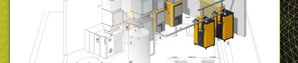
3 Smap3D Plant Design Intelligent 2D/3D Plant and Piping Design Smap3D Plant Design is 3D CAD software for the fast, easy design of 3D piping systems used in mechanical engineering, equipment production and plant design. Smap3D Plant Design provides an integrated software solution for an optimal plant design process chain. Smap3D P&ID 2D flowcharts, the first link in the process chain, are among the most important documents in plant design. Our integrated P&ID To Do List function provides a simple easy connection between flowcharts and the 3D model. Smap3D Piping 3D piping design, the second link in the process chain, is highly automated with the Smap3D Piping add in. The automation is based on specifications (classes) which make it possible to create a highly powerful 3D plant design solution from the 3D CAD system. Smap3D Isometric The isometric drawing is the third link in the process chain. The piping isometric is a single line technical drawing in the form of an isometric representation for the production of piping systems. We use ISOGEN from the market leader Alias. From P&ID diagram to 3D design to isometrics Integrated process reliability for plant engineers through a single software

4 Smap3D P&ID Intelligent application for process engineering Create, modify and manage with database support With this software, independent of the CAD system, all relevant drawings, data, evaluations and inspections are generated in a single database from a single initial drawing all the way through the entire project. Smap3D P&ID automates and simplifies repetitive tasks. All drawings, project sheets and reports are template based and thus 100% configurable. Process continuity through the integration of P&ID in Smap3D Piping. Dynamic lines (systems) automatically respond to separation and closing (for example, in the installation of symbols). "Design Checks" for evaluating individual P&ID drawings or the entire project for completeness, validity and accuracy. Automatic search of TAG numbers through the system. Expansion of the symbol libraries (ISO / DIN, ISA) and component database with company specific symbols and components (as intelligent PDFs and as 2D geometry in DXF and DWG formats). P&ID To Do List The intelligent 3D connection The P&ID To Do List is a function integrated in Smap3D Plant Design which creates an intelligent connection between Smap3D P&ID Schematic and 3D piping design with Smap3D Piping. The existing attributes of the symbols and lines defined in the P&ID by a process engineer can be evaluated automatically with the P&ID To Do List. For the designer in 3D CAD, they serve as a basis for creating 3D piping systems and as support for the entire 3D plant design.
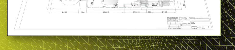
5 Smap3D Piping Integrated Piping Design in the CAD Environment The integrated Smap3D Piping software turns the CAD system into a high performance 3D plant engineering solution. Thus 3D Piping can be used within the individual CAD system. A standalone solution is in development. Smap3D Piping automatically generates complete, three dimensional pipelines with the proper fittings from the sketched pipeline paths. Smap3D Piping supports the installation of additional components (e.g. valves, instruments). The existing pipelines are separated and the required connections (e.g. flanges) are set up. Changes to the pipeline path are automatically updated. Smap3D Piping uses pipe specifications which determine the conformity of components (fittings, valves, etc.) to the pipe characteristics (diameter, pressure, medium, etc.). These pipe specifications control the numerous automatic functions of the software. This technology enables convenient 3D pipeline design and process reliability. Errors by individual users are prevented. 3D mechanical engineering and piping design directly in a 3D CAD environment Conveniently create 3D piping systems with pipe classes Smap3D Isometric Automatic Creation of Isometrics The software exports all 3D pipeline information and automatically creates the isometric drawing. The basic software is ISOGEN from the market leader Alias. Create piping isometrics from the 3D assembly at the touch of a button. Export of information for pipeline simulation (SIGMA ROHR2 / CEASAR II ). The creation of the pipeline figures as well as all corresponding information such as dimensions, cross hatches, annotations is done automatically via pre adjustable parameters (styles) that can be configured individually. Various BOMs (e.g. material or welding parts lists) can be automatically displayed on the drawing and/or generated as an ASCII file for transfer to an inventory control system. User friendly generation of isometrics and reports


6 Primary Functions of Smap3D Piping A comprehensive library for plant engineering allows immediate implementation of the Smap3D Piping software. Various international standards are available: DIN/IS0, ANSI, UNI, GB, JIS, GOST. All cross sections Smap3D Piping can process freely defined system crosssections. Even non circular cross sections for cable ducts, air ducts, etc. can be efficiently designed. Automatic generation and modification of complete piping systems After selecting the pipe classes, pipelines are generated at the touch of a button. The user must only define the path; the software takes care of the rest automatically. Line reductions and extensions can be implemented with just a few clicks of the mouse. All necessary work such as separating lines, shortening pipes, changing the diameter, etc. is done automatically by Smap3D Piping. Insulation is defined in the pipe classes. For each diameter, an individual value for the dimension is stored. Insulation and fittings required for breaks are generated automatically. Extrusions and OLETs may be used at branches as an alternative to T components. Normally inserted by time consuming mechanical processing, Smap3D Piping creates the extrusions automatically. CADENAS purchased parts catalogs Full integration of the purchased parts catalogs from the market leader CADENAS. Purchased parts for plants such as pumps and valves can be integrated in Smap3D Plant Design. Bill of materials For pipelines created with Smap3D Piping, all information relevant to the plant design is available for BOMs. The BOMs can be created using the CAD system and/or via the isometrics.


7 Smap3D ScanToCAD Faster realization of existing projects With Smap3D ScanToCAD, designers can more quickly transfer existing physical surfaces and geometries from 3D scans/point clouds into the CAD, instead of drawing these themselves! How it works in practice: The physical object is transferred directly into the 3D drawing in the PC via the point clouds. Efficient transfer from 3D scan into your 3D CAD system Step 1: 3D scanning The designer scans the actual object or authorizes a local surveyor s office. Advantages to contracting a surveyor s office: travel expenses as well as in house staff costs and the purchase of a 3D laser scanner are eliminated. Step 2: Read in scanned data The designer obtains various scans that are now referenced in relation to each other with the help of Smap3D ScanToCAD. This means the designer can combine the individual scans and incorporate them into an overall project. Advantage: Smap3D ScanToCAD can read in and manage common scan formats. Step 3: Selection and data export The designer selects which areas and geometries are currently required. These are exported to the CAD system. Advantage: Instead of point clouds with high data volume, selected areas and geometries are transferred into the 3D CAD. This eliminates a hugely time consuming process the volume of data is significantly reduced! Point clouds 3D CAD view Functional overview Evaluation of 3D scatter plots through effective reconstruction tools Export of standard geometries from the scatter plot into the 3D CAD target system Support of all major scanner formats/ types such as ASCII, Faro, Leica, Optech, Riegl, Topcon, Trimble, Zoller and Fröhlich or E57 Computation of photographic representations from the laser scanner s reflectance values or from the color photographs Fast and effective reconstruction of technological equipment, designed for straight pipe flows, bends, valves or branches

8 CAD Partner is a global provider of software and services for mechanical engineering and plant design. The proprietary product Smap3D Plant Design meets the needs of the entire plant design process chain. For more information about the products and services of CAD Partner, visit CAD Partner GmbH Am Marktplatz Nittendorf Germany Phone: info@cadpartner.de North and South America CAD Partner, LLC United States Phone: info@smap3d.com Asia CAD Partner Technology (Asia), Ltd. Hong Kong Phone: sales@smap3d.com.cn CAD Partner Technology (Asia), Ltd. China Phone: sales@smap3d.com.cn Smap3D Plant Design needs no further system requirements. The recommended system requirements of the supporting CAD systems are sufficient CAD Partner GmbH. All rights reserved A Subject to change EN/LE
Outfitting Detail Design suite
 Outfitting Detail Design suite 2015Q3 The Cadmatic 3D Outfitting Detail Design suite is an integrated, databasedriven design module and provides powerful tools for 3D layout-, piping-, HVAC-, cable tray-
Product content. Common for both Research and Commercial Editions. Solidworks DCAD Matrix. Coimbatore Cad Solutions Pvt Ltd.
 Product content Common for both Research and Commercial Editions Solidworks 2018 3DCAD Matrix Coimbatore Cad Solutions Pvt Ltd Page 1 of 7 3D CAD MATRIX SOLIDWORK PREMIUM PROFESSIONAL STANDARD Ease of
GET Smart Educating Unintelligent Objects. Sonia Delgadillo
 GET Smart Educating Unintelligent Objects Sonia Delgadillo Educating Unintelligent Objects CADWorx provides fast implementation for adding custom components to the catalog and project specification. CADWorx
FOCUS ON REAL DESIGN AUTOMATE THE REST CUSTOMTOOLS BATCH CONVERTING YOUR SOLIDWORKS FILES
 FOCUS ON REAL DESIGN AUTOMATE THE REST CUSTOMTOOLS BATCH CONVERTING YOUR SOLIDWORKS FILES Table of Contents BATCH CONVERTING YOUR SOLIDWORKS DOCUMENTS... 3 Introduction... 3 What does it do?... 3 How does
The Benefits of Using the Electrical Toolset in AutoCAD
 The Benefits of Using the Electrical Toolset in AutoCAD A productivity study detailing the differences between AutoCAD and the Electrical toolset. Built specifically to create and modify electrical controls
Isometrics COMOS. Process Isometrics. Trademarks 1. Introduction 2. Project structure 3. Isometric report 4. Engineering with COMOS Isometrics
 Trademarks 1 Introduction 2 COMOS Process Operating Manual Project structure 3 Isometric report 4 Engineering with COMOS 5 Creating an isometric drawing from existing 3D data 6 IDF import 7 Administration
Comprehensive GD&T Evaluation Software for Manufacturing Quality Control
 Comprehensive GD&T Evaluation Software for Manufacturing Quality Control Model-Based Family of Software EVOLVE SmartProfile Comprehensive GD&T Evaluation Software for Manufacturing Quality Control Easy
SEMPEO SQA Unit Code FP49 04 Producing CAD models (drawings) using a CAD system
 using a CAD system") Producing CAD models (drawings) using a CAD system Overview This standard covers a broad range of basic competences that you need, to set up and operate a computer aided drawing (CAD) system to produce
Producing CAD models (drawings) using a CAD system Overview This standard covers a broad range of basic competences that you need, to set up and operate a computer aided drawing (CAD) system to produce
AVEVA PDMS. Business Benefits. Accurate and clash-free 3D plant design
 AVEVA PDMS Accurate and clash-free 3D plant design With ever increasing global demand for products from process and power plants, AVEVA PDMS enables companies to design, construct and maintain high quality
Autodesk InventorTM. Routed Systems Suite 2008
 Autodesk InventorTM Routed Systems Suite 2008 Add the power of 3D with the company that brought you 2D. Autodesk Inventor software products are the best choice for AutoCAD software users who want to add
PDS V8 SE Training Course Highlights
 PDS V8 SE Training Course Highlights Course Number Title Est. No of Days Per Enrollment (US $) On-Site Excl. Travel (US $) TPDS3113 PDS 3D Theory 4 2000 10000 TPDS3100 PDS Project Administration 4 2000
SOLIDWORDS 3D CAD MATRIX
 SOLIDWORDS 3D CAD MATRIX SOLIDWORKS PROFESSIONA L SOLIDWORKS PREMIUM Ease of Use Learn Fast: InContext and Toolbar Menus, Command Search, BuiltIn Tutorials, Searchable Help Documentation SOLIDWORK S STANDARD
Smart 3D Plant/Outfitting Curriculum Path & Training Guidelines
 Smart 3D Plant/Outfitting Curriculum Path & Training Guidelines Intergraph PPM recommends that new Smart 3D plant/outfitting users select one of the following training tracks described below. 1. System
CADprofi Table of contents list of new features in CADprofi 11.07:
 11.07 Table of contents list of new features in CADprofi 11.07: - CADprofi Architectural - CADprofi Electrical - CADprofi Mechanical - CADprofi HVAC & Piping - General commands (affects all modules) -
FEST Engineering Ltd. Technical Company for Engineering, Calculation and Design of Energy Facilities
 FEST Engineering Ltd. Technical Company for Engineering, Calculation and Design of Energy Facilities ABOUT US In operation since 2005, first as FEST Engineering s.r.o., now FEST Engineering Ltd., was originally
THINK IN NEW DIMENSIONS. Software & Services for Industrialised Construction
 THINK IN NEW DIMENSIONS Software & Services for Industrialised Construction O P E N B I M Integrated planning The objective of an integrated planning is the consistency of data and information throughout
Chemionix Solutions. Outsourcing. Engineering. Drafting
 Chemionix Solutions. Outsourcing. Engineering. Drafting Chemionix Your Outsourcing Partner Companies have been outsourcing since time began. It is only recently that business processes can be outsourced
For more accurate electrical controls design, there s a logical choice: AutoCAD Electrical.
 For more accurate electrical controls design, there s a logical choice: AutoCAD Electrical. If you design machines or products that move, electrical controls are probably a key component of your design
Overview. Branched connection (using an o-let or saddle component) Profile (hole) cut into the pipe run. Pipe is not broken
 Profile (hole) cut into the pipe run. Pipe is not broken") Overview A piping component (to cut) for routed system is considered when the component is placed onto a pipe run and a profile cut occurs in the pipe route at the inserted point. See Content Center Piping
Overview A piping component (to cut) for routed system is considered when the component is placed onto a pipe run and a profile cut occurs in the pipe route at the inserted point. See Content Center Piping
Plant Design work flow Using Autodesk Plant Design Suite Ultimate. Carlos Caminos CAD Manager - Venture Engineering & Construction, Inc.
 Plant Design work flow Using Autodesk Plant Design Suite Ultimate Carlos Caminos CAD Manager - Venture Engineering & Construction, Inc. Class Summary In this class, you will learn about a proven oil and
OmniWin 2015 Professional Designing and Nesting
 OmniWin 2015 Professional Designing and Nesting OmniWin 2015 is a simple, clear and fast designing and nesting software, which adapts intelligently to your machine and your cutting needs. It takes over
Leading in drainage. Made in Germany
 Made in Germany Leading in drainage 2 Overview SmartServices KESSEL AG KESSEL SmartServices Operation Design Installation Our digital services offer With KESSEL SmartServices the future has already arrived
Bentleyuser.dk ÅRSMØDE 2011 Vejle,
 2011 Bentley Systems, Incorporated Bentleyuser.dk ÅRSMØDE 2011 Vejle, 14.+15.11.2011 Bentley OpenPlant Update Carsten Gerke Senior Sales Director Bentley Plant EMEA Today s Agenda 2010 Bentley Systems,
Plant & Process Electrical Design Introduction to I&W, promis e & BRCM
 2014 Bentley Systems, Incorporated Plant & Process Electrical Design Introduction to I&W, promis e & BRCM Rick Black- Industry Sales Director - Electrical Group EMEA 3 WWW.BENTLEY.COM 2014 Bentley Systems,
Autodesk Inventor LT. Easy as 1, 2, 3D.
 Autodesk Inventor LT Easy as 1, 2, 3D. Model Your Part Designs in 3D With parametric 3D solid part modeling in Autodesk Inventor LT software, you can model your part designs in 3D instead of simply drawing
CADprofi Summary of main changes made to the program since the CADprofi version.
 11.01 Summary of main changes made to the program since the CADprofi 10.01 version. CADprofi Architectural extension of the woodwork library Additional types of windows and doors have been added to the
Power tools for mechanical design. AutoCAD. Mechanical
 Power tools for mechanical design. AutoCAD Mechanical The AutoCAD Mechanical Advantage To compete and win in today s design marketplace, engineers need to create and revise mechanical drawings faster than
Getting Started Guide
 SOLIDWORKS Getting Started Guide SOLIDWORKS Electrical FIRST Robotics Edition Alexander Ouellet 1/2/2015 Table of Contents INTRODUCTION... 1 What is SOLIDWORKS Electrical?... Error! Bookmark not defined.
GstarCAD Mechanical 2015 Help
 1 Chapter 1 GstarCAD Mechanical 2015 Introduction Abstract GstarCAD Mechanical 2015 drafting/design software, covers all fields of mechanical design. It supplies the latest standard parts library, symbols
SEMETS3-05 Producing engineering drawings/models using 3D computer aided techniques
 Producing engineering drawings/models using 3D computer aided Overview This unit identifies the competences you need to set up and operate a computer aided drawing (CAD) system to produce three-dimensional
Producing CAD models (drawings) using a CAD system
 using a CAD system") Unit 061 Producing CAD models (drawings) using a CAD Level: 2 Credit value: 11 NDAQ number: 500/9514/6 Unit aim This unit covers the skills and knowledge needed to prove the competences required to set
Unit 061 Producing CAD models (drawings) using a CAD Level: 2 Credit value: 11 NDAQ number: 500/9514/6 Unit aim This unit covers the skills and knowledge needed to prove the competences required to set
Advance Automation & Electronics (AAE)
") Advance Automation & Electronics (AAE) Advance Automation & Electronics (AAE) is an Industrial Control Automation company and one of the leading Training providers in PLCs, AC/VFD Drives, Motor Control
Advance Automation & Electronics (AAE) Advance Automation & Electronics (AAE) is an Industrial Control Automation company and one of the leading Training providers in PLCs, AC/VFD Drives, Motor Control
Technical English -I 4 th week ENGINEERING DRAWING
 Technical English -I 4 th week ENGINEERING DRAWING What is engineering drawing? It is the art of representation of geometrical objects on a drawing sheet. An engineering drawing is used to fully and clearly
Design for fireplace setting by Ross Ubergang rossu.com.au. gcadplus User Guide v gcad +
 This chapter focuses on the use of common drawing tools needed to create typical landscape drawings. You will learn to use these draw tools by making an accurate, full-size model of a proposal for a space
Specification D data models
 Previous Edition Specification 2017-04 Class: Dimensions, tolerances Class No.:01 Documentation of components by means of 3D data models 516 Part name (for databases) 2009-09 3D data models 852 005 160
Table of contents. User interface 1: Customizable tool palette... 6 User interface 2: General GUI improvements... 7
 Table of contents WELCOME TO ADVANCE CONCRETE 2014... 5 USER INTERFACE ENHANCEMENTS... 6 User interface 1: Customizable tool palette... 6 User interface 2: General GUI improvements... 7 MODELING... 10
Mechanical Design. Brian Brinson Mechanical Design Manager.
 Mechanical Design Brian Brinson Mechanical Design Manager brian.brinson@spx.com September 26, 2018 Agenda 1. Design Process 2. Pre-Approval Drawings Bid Drawings Preliminary Drawings 3. Approval Package
ATHENA2012. The new upgrade raises the bar on productivity. An even better return on investment
 ATHENA2012 The new upgrade raises the bar on productivity An even better return on investment The new version of ATHENA 2012 certainly meets that claim. The 3D Modeling Program has increased functionality
Ball Valve Assembly. On completion of the assembly, we will create the exploded view as shown on the right.
 Ball Valve Assembly Supplied are the main components of a ball valve. In this exercise you will assemble the valve as shown below Left. (N.B. Socket head cap screws are not supplied these will be created
Visual Pipe Stress Analysis for AutoCAD Plant 3D
 Page 1 of 7 Visual Pipe Stress Analysis for AutoCAD Plant 3D AutoCAD Plant 3D 2015 and checkstress It is common practice for piping designers to consider space constraints, process and flow constraints
SEMETS3-04 Producing mechanical engineering drawings using computer aided techniques
 Producing mechanical engineering drawings using computer aided Overview This unit identifies the competences you need to set up and operate a computer aided drawing (CAD) system to produce fully detailed
AutoCAD Plant 3D so that. will walk
 In this paper, you will learn how to customize the isometricss produced by AutoCAD Plant 3D so that they will meet your CAD and engineering standards as well as the standards of your client. This paper
AutoCAD Electrical Fundamentals with NFPA Standards
 AutoCAD Electrical Fundamentals with NFPA Standards Course Length: 3 days The AutoCAD Electrical Fundamentals with NFPA Standards training course covers the indispensable core topics for working with the
Drawing Module, Import-Export
 Drawing Module, Import-Export construction modelling systems www.comosys.com Save Time & Money In the engineering & design business one of the biggest issues is man-hours. How to get work done quickly
Introduction to Engineering Design. Part A
 Introduction to Engineering Design Final Examination Part A Spring 2005 Student Name: Date: Class Period: Total Points: Directions: Select the letter of the response which best completes the item or answers
Mick Hodgson. Tekla Structures, Tekla Versions And Software Evolution
 Mick Hodgson 2018 Tekla Structures, Tekla Versions And Software Evolution Tekla Version 15 Main Points Unlimited Models Quick modelling tools Fast drawing production Tube CNC Tekla Version 15 Main Points
Mechanical Design CATIA - Interactive Drafting 1 (ID1) CATIA V5R20
 CATIA V5R20") Mechanical Design CATIA - Interactive Drafting 1 (ID1) CATIA V5R20 Mechanical Design CATIA - Interactive Drafting Address 2D design and drawing production requirements. Product overview Interactive Drafting
Mechanical Design CATIA - Interactive Drafting 1 (ID1) CATIA V5R20 Mechanical Design CATIA - Interactive Drafting Address 2D design and drawing production requirements. Product overview Interactive Drafting
Solid Edge structural frames and weldments
 Siemens PLM Software Solid Edge structural frames and weldments White Paper Intelligent, process-specific applications that speed time to manufacturing. www.siemens.com/plm A white paper issued by: Siemens
DRAFT Solid Edge ST4 Update Training Draft
 DRAFT Solid Edge ST4 Update Training Draft Presented by: Steve Webb Topics Parts List Table Titles Column Headers Headers Merging Header Rotate Cell Aspect Ratio Cell Formatting Overriding Disabled Cells
Future of Bentley Plant applications: AutoPLant and OpenPlant
 1 WWW.BENTLEY.COM 2013 Bentley Systems, Incorporated Future of Bentley Plant applications: AutoPLant and Magnus Cullberg 2 WWW.BENTLEY.COM 2013 Bentley Systems, Incorporated AutoPLANT Modeler AutoPLANT
Autocad d 3d Mechanical Manual Command
 Autocad 2018 2d 3d Mechanical Manual Command If searched for a ebook Autocad 2018 2d 3d mechanical manual command in pdf form, in that case you come on to right website. We furnish complete variant of
Mastering AutoCAD 2D
 Course description: Mastering AutoCAD 2D Design and shape the world around you with the powerful, flexible features found in AutoCAD software, one of the world s leading 2D design applications. With robust
Engineering Design & Power Training Institute
 Engineering Design & Power Training Institute Recognition & Approvals Association of Power & Design Engineers (APDE) An ISO 9001: 2008 Certified Institute Courses P G Diploma in Piping Design & Details
Advance Concrete 2014 Service Pack 1
 Advance Concrete 2014 Service Pack 1 This document describes the improvements in Service Pack 1 for Advance Concrete 2014. GENERAL Interaction between Advance Concrete and Advance Steel. Advance Steel
COURSE CONTENTS FOR THE AVTS COURSES
 Revision: 00 LEARNING CONTENT Page 1 of 14 COURSE CONTENTS FOR THE AVTS COURSES AT CAD- CAM LAB, ATI, VIDYANAGAR, HYDERABAD Revision: 00 LEARNING CONTENT Page 2 of 14 III COURSE CODE CAD-01 IV COURSE TITLE
Services Overview. Northeast Blueprint
 Services Overview 2D CAD Conversions Paper to CAD 2D CAD Conversions Construction Engineering / CAD Services Construction Markups Consultant Drawings Coordinated Drawings As -Builts Steel Structural Detailing
Mr. Wolfgang Metzen was trained as a mechanical
 Germany AKUSTEC Implementation of PULSE into Automotive Test Cells Automotive, Consultants PULSE Solutions Akustec, based near Munster, Germany, is a consultancy company which was founded by Mr. Wolfgang
PDMS INFORMATION BOOKLET. Date: 15/08/2013 SEPC
 PDMS INFORMATION BOOKLET Date: 15/08/2013 OTHER SERVICES ON OFFER BY PIPING STRESS ANALYSIS USING CEASER II EQUIPMENT DESIGN USING PV ELITE ISOMETRIC & P&ID IN AUTOCAD version 2012 MATERIAL INSPECTION
Sketching & Auto CAD (Computer Aided Design) - Mechanical Design
 - Mechanical Design") Western Technical College 10606113 Sketching & Auto CAD (Computer Aided Design) - Mechanical Design Course Outcome Summary Course Information Description Career Cluster Instructional Level Total Credits
Western Technical College 10606113 Sketching & Auto CAD (Computer Aided Design) - Mechanical Design Course Outcome Summary Course Information Description Career Cluster Instructional Level Total Credits
Straight ahead to better designs and happier clients
 lindab itline lindab itline Straight ahead to better designs and happier clients What if we could help you shorten your design phase, minimizing the risks, and creating better designs? Would that give
AVEVA PDMS 12.0 The 3D plant design application for accurate and clash-free plant design
 AVEVA PDMS 12.0 The 3D plant design application for accurate and clash-free plant design The process and power industries seek to commission high-quality plant earlier, and to bring it on line with minimum
AECOsim Building Designer. Quick Start Guide. Chapter A08 Space Planning Bentley Systems, Incorporated
 AECOsim Building Designer Quick Start Guide Chapter A08 Space Planning 2012 Bentley Systems, Incorporated www.bentley.com/aecosim Table of Contents Space Planning...3 Sketches... 3 SpacePlanner... 4 Create
The Most Efficient SMT Solder Paste Stencil Cutter Available LPKF StencilLaser G 6080
 The Most Efficient SMT Solder Paste Stencil Cutter Available LPKF StencilLaser G 6080 Improved Quality No Chiller Needed In Process Inspection Specific Configurations Stencils up to 1 600 mm long See for
Tips & Tricks - HiCAD
 Tips & Tricks - HiCAD Alles einblenden/ausblenden - Expand/Collapse All Tips & Tricks 2018 Tips & Tricks 2017 Tips & Tricks 2018 HiCAD - Remote Maintenance (November 2018) When you install HiCAD 2018 (as
Model-Based Definition using Creo Parametric and GD&T Advisor
 Model-Based Definition using Creo Parametric and GD&T Advisor Ted Anderson Product Line Manager Sigmetrix, LLC Model-Based Definition What is it? Why Model-Based Definition? What tools are required to
THE CR SPECIALISTS HD-CR CR 35 NDT
 THE CR SPECIALISTS HD-CR CR 35 NDT COMPUTED RADIOGRAPHY SYSTEMS Digital Intelligence Ready to Change. www.duerr-ndt.com VERSATILE AND DEPENDABLE HIGH-TECH MADE IN GERMANY Highest resolution DÜRR NDT is
Inventor 2013 What s New!
 Reference 2011070 28 th March 2012 Guide by Luke Davenport Inventor 2013 What s New! A brief snapshot of the most exciting new features in the 2013 release, as selected by CADline. The complete list of
*CEL International is now WSP CEL
 * *CEL International is now WSP CEL For over 40 years, companies in the pharmaceutical and process industry have found in CEL an invaluable process plant contractor and engineering partner with an impressive
Milling and turning with SINUMERIK:
 Milling and turning with SINUMERIK: CNC solutions for the shopfloor SINUMERIK Answers for industry. Simple to set up... Contents Shopfloor solutions for CNC machines with SINUMERIK Milling with the SINUMERIK
This document has been carefully prepared with all the information needed to properly use this Advance product. This document contains a brief
 This document has been carefully prepared with all the information needed to properly use this Advance product. This document contains a brief description of the software functions and is not a replacement
More Light and Speed in Production Control CORE
 More Light and Speed in Production Control CORE CORE The Centre for Production Metrology Developed to speed production, CORE provides the ultimate in flexible 3D inspection solutions for advanced part
Producing mechanical engineering drawings using a CAD system
 Unit 804 Producing mechanical engineering drawings using a CAD system UAN: J/600/5794 Level: Level 2 Credit value: 11 GLH: 61 Relationship to NOS: This unit has been derived from national occupational
Metalsa: Automated Quality Control of Formed Sheet Metal Parts
 Application Note Metalsa: Automated Quality Control of Formed Sheet Metal Parts Location / country: Bergneustadt, Germany GOM system: ATOS ScanBox 6130 GOM software: ATOS Professional Sector: automotive
How we build reality. Company Overview. Scanning in Explosive Environments
 How we build reality Scanning in Explosive Environments Case Study Offshore Company Overview Z+F is one of the world leading manufacturers of phase based laser scanners. Our strengths lie in the powerful
PRODUCT DESIGN PROCESS
 PRODUCT DESIGN PROCESS Introduction Product design has two aspects: technical design and aesthetic design. Technical design is process of defining all the performance and physical characteristics of a
ATHENA2014. Drawing, planning, designing be even more productive with the new upgrade! Really fast! Really good!
 ATHENA2014 Drawing, planning, designing be even more productive with the new upgrade! Really fast! Really good! With the development of the ATHENA 2014 Upgrade the emphasis this time is on increasing productivity.
FINE-HVAC New Release 9 NG: The New Generation of the Integrated Software Tool for HVAC Design (by 4M Support department)
") FINE-HVAC New Release 9 NG: The New Generation of the Integrated Software Tool for HVAC Design (by 4M Support department) 1. Introduction FineHVAC, the standard software tool for HVAC design, combines
FINE-HVAC New Release 9 NG: The New Generation of the Integrated Software Tool for HVAC Design (by 4M Support department) 1. Introduction FineHVAC, the standard software tool for HVAC design, combines
Learn How to Optimize Heat Exchanger Designs using Aspen Shell & Tube Mechanical
 Learn How to Optimize Heat Exchanger Designs using Aspen Shell & Tube Mechanical A self guided demo to get started with Aspen Shell & Tube Mechanical Why Use Aspen Shell & Tube Mechanical? Aspen Shell
OpenPlant. Hayley Brown Industry Consultant, Bentley Plant Bentley Systems, In
 OpenPlant Hayley Brown Industry Consultant, Bentley Plant tley Systems, In co Introduction What is OpenPlant? OpenPlant is the branding for the next generation of applications and tools based on ISO 15926
DDS-CAD Technical Telegram Issue 3 December 2011
 DDS-CAD Technical Telegram Issue 3 December 2011 Dear, Enjoy reading the new issue of our technical telegram. We hope that our tips and tricks will improve your efficiency and will make it even more interesting
Autodesk Plant Design Suite. Build on the power and familiarity of AutoCAD software with multidiscipline plant design solutions.
 Autodesk Plant Design Suite Build on the power and familiarity of AutoCAD software with multidiscipline plant design solutions. The Suite Advantage: Convenient, Comprehensive, Cost-Effective Autodesk Plant
Sheet Metal Punch ifeatures
 Lesson 5 Sheet Metal Punch ifeatures Overview This lesson describes punch ifeatures and their use in sheet metal parts. You use punch ifeatures to simplify the creation of common and specialty cut and
WELCOME TO CHEMIONIX. Chemionix e-solutions Pvt Ltd Mumbai India
 WELCOME TO CHEMIONIX Mumbai CHEMIONIX: YOUR OUTSOURCING PATNER Companies have been outsourcing since time began. It is only recently that business processes can be outsourced across countries and continents.
Our mission. Tooling systems and application consulting for the milling of complex 2.5 and 3D geometries
 Our mission Tooling systems and application consulting for the milling of complex 2.5 and 3D geometries Who we are Pokolm Frästechnik GmbH & Co. KG stands for the development and manufacture of innovative,
RISONIC Ultrasonic Transit Time Flow Measurement For Filled/Partially Filled Pipes For Open Channels. Supply Disposal Hydraulic Power Station
 RISONIC 2000 Ultrasonic Transit Time Flow Measurement For Filled/Partially Filled Pipes For Open Channels Supply Disposal Hydraulic Power Station F1 F2 F3 F4 F5 Conditions for Accurate Flow Measurement
CAD / CAM / CAE Services. Parikh Info Solutions Pvt. Ltd.
 CAD / CAM / CAE Services Parikh Info Solutions Pvt. Ltd. About Us Established in 1998, PISPL has built a reputed name in the market. Our highly experienced and trained team ensures the highest quality
National Standard Details Library An Electronic Library of Parametric CAD Details
 National Standard Details Library An Electronic Library of Parametric CAD Details James Nyambayo and Robert Amor Building Research Establishment Bucknalls Lane, Garston, Watford, WD2 7JR, UK Phone +44-1923-664168.
Cymap Mechanical. Reference: CYMECH_1117_v1. Page 1 of 30. Cymap Mechanical
 Page 1 of 30 Cymap Mechanical Page 2 of 30 Contents Cymap Mechanical Overview... 3 Building Program... 4 Energy Program... 9 Ductwork Program... 15 Pipework Program... 18 Public Health Program... 22 Psychrometrics
Sicat Master. Engineering of overhead contact line systems. siemens.com/rail-electrification
 Sicat Master Engineering of overhead contact line systems siemens.com/rail-electrification When engineering overhead contact lines for mass transit and main line railways, we combine the calculations of
Engineering Working Drawings Basics
 Engineering Working Drawings Basics Engineering graphics is an effective way of communicating technical ideas and it is an essential tool in engineering design where most of the design process is graphically
Why Moving from AutoCAD to AutoCAD MEP Just Makes Sense!
 AUTOCAD MEP Why Moving from AutoCAD to AutoCAD MEP Just Makes Sense! If you create building mechanical, electrical, or plumbing (MEP) construction documents and are currently working with AutoCAD software
SIGMA Ingenieurgesellschaft mbh
 Software & Engineering PROBAD PROBAD Overview PROBAD is a solution for the code-based strength calculations of pressure parts. It allows re-checking, designing or optimizing of vessel- and pipe components
Stepping ahead in technology & innovation PIPING INSTITUTE OF TECHNOLOGY & ANALYSIS SOLUTIONS
 Stepping ahead in technology & innovation PIPING INSTITUTE OF TECHNOLOGY & ANALYSIS SOLUTIONS PIPING ENGINEERING & PLANT DESIGN Chapter 1. Introduction of Piping Industry & Role of Piping Engineer 1.1.
What s New in Autodesk Advance Steel 2018
 What s New in Autodesk Advance Steel 2018 CADPRO Systems Ltd Advance Steel Team New & enhanced features in Autodesk Advance Steel 2018 Prefabricated handrail with balls Wall mounted grab rail Cold rolled
CP-System. User s guide. Copyright 2009 CAD-Profi
 e-mail: info@cadprofi.com, http://www.cadprofi.com CP-System User s guide Copyright 2009 CAD-Profi Contents Introduction 4 About CAD-Profi programs 4 Important information about working in CP-System 5
Wiring Projects. Chapter 5 Wiring Diagrams March 29, Wire List Wire List 3/28/2010
 Chapter 5 Wiring Diagrams March 29, 2010 Wiring Projects Electronic schematics are required to completely describe how the wiring will be connected to the components. The Cad Technician will develop the
HydroFORM Phased Array Corrosion Mapping System Part 2 Mechanical Setup
 HydroFORM Phased Array Corrosion Mapping System Part 2 Mechanical Setup HydroFORM Corrosion Mapping System Mechanical Setup The HydroFORM Phased Array System is designed to perform corrosion mapping in
One-Stop Solution for Foundation Design
 [Automated Foundation Engineering System] One-Stop Solution for Foundation Design Civil & Architecture Team Jbchoe@gsconst.co.kr 2006.11.02 (Automated Foundation Engineering System) Contents 1. General
LENORD. +BAUER... automates motion. MiniCoder GEL 2444K Speed and position sensor with metal housing and sin/cos output
 MiniCoder GEL 2444K Speed and position sensor with metal housing and sin/cos output LENORD +BAUER... automates motion. Technical information Version 03.3 General The measuring unit comprises a sensor and
User Guide V10 SP1 Addendum
 Alibre Design User Guide V10 SP1 Addendum Copyrights Information in this document is subject to change without notice. The software described in this document is furnished under a license agreement or