Generative Drafting Overview What's New Getting Started User Tasks
|
|
|
- Lizbeth Boone
- 6 years ago
- Views:
Transcription
1 Generative Drafting Overview Conventions What's New Getting Started Defining the Drawing Sheet Part Drawing Opening a Part Creating a Front View Creating a Projection View Creating a Section View Creating a Detail View Creating a Section Cut Assembly Drawing Opening an Assembly Creating a Frame and a Title Block Creating Views via the Wizard Creating a Section View Overloading Element Properties Generating Balloons and a Bill of Material Creating an Isometric View and Changing its Properties User Tasks Basic Tasks Drawing Management Creating a New Drawing Opening a Drawing Editing Drawing Links Updating Drawings Via the Batch Monitor Sheets Defining a Sheet Modifying a Sheet Creating a Frame and a Title Block Inserting an Image Into a Frame and Title Block Managing a Background View View Creation Before You Begin Creating a Front View Creating an Advanced Front View Creating a Projection View Creating an Unfolded View Creating a View from 3D
2 Creating an Auxiliary View Creating an Offset Section View / Cut Creating a Section View / Cut (Planar Surface) Creating an Aligned Section View / Cut Creating a Section View / Cut with Profile Defined in 3D Creating a Detail View / Detail View Profile Creating a Quick Detail View / Quick Detail View Profile Creating a Clipping View / Clipping View Profile Creating an Isometric View Creating an Exploded View Creating a Broken View Creating a Breakout View Creating Views via the Wizard View Update Reporting View Modification Before you begin Moving a View Positioning a View Positioning a View Independently of its Reference View Locating Reference/Resulting Views Isolating Generated Views Restoring Deleted Generated Elements Locking a View Scaling a View Renaming a View Modifying a View Projection Plane Generating a Bill of Material Generating Balloons on a View Showing Geometry in Views Modifying a Callout Graphism Modifying a Callout Geometry Overloading Element Properties Modifying a Pattern Duplicating Generative Geometry Modifying a view's links Applying a view's links to another view Generative View Styles Creating a View using Generative View Styles Switching a View to Another Generative View Style Applying the Generative Style of a View to Another View Applying a Generative View Style to a View Dimension Generation About Dimension Generation Generating Dimensions in One Shot Filtering Dimension Generation Generating Dimensions Semi-Automatically Analyzing Generated Dimensions Positioning Dimensions (View per View) Analyzing Interfering Dimensions Driving 3D Constraints via Generated Dimensions
3 Dimension Manipulation Creating Associative Thread Dimensions Technological Feature Dimensions Before you Begin Creating Intra-Technological Feature Dimensions Creating Inter-Technological Feature Dimensions Annotations Dress-Up Elements Properties Images Printing Interoperability Creating and Modifying Views from a.model File Export and Import Administration Tasks Before you begin Administering Generative View Styles and Standards Setting Generative View Style Parameters Before you begin Generate Parameters View Dress-Up parameters Drafting Interoperability Working with ENOVIA LCA Managing CATDrawing Documents in ENOVIA LCA Optimal CATIA PLM Usability for Drafting Working with ENOVIA VPM Managing CATDrawing Documents in ENOVIA VPM Optimal CATIA PLM Usability for Drafting Workbench Description Menu Bar Generative Drafting Toolbars Drawing Views Generative View Style Dimension Generation CATDrawing Specification Tree Icons Customizing Customizing Settings General Layout View Generation Geometry Dimension Manipulators Annotation and Dress-Up Administration Customizing Toolbars Glossary
4 Index
5 Overview Welcome to the Generative Drafting User's Guide. This guide is intended for users who need to become quickly familiar with the Generative Drafting Version 5 product. This overview provides the following information: Generative Drafting in a Nutshell Before Reading this Guide Getting the Most Out of this Guide Accessing Sample Documents Conventions Used in this Guide Generative Drafting in a Nutshell Version 5 Generative Drafting is a new generation product that provides users with powerful functionalities to generate drawings from 3D parts and assembly definitions. The Generative Drafting User's Guide has been designed to show you how to generate drawings of varying levels of complexity, as well as apply dimensions, annotations and dress-up elements to these drawing. Before Reading this Guide Before reading this guide, you should be familiar with basic Version 5 concepts such as document windows, standard and view toolbars. Therefore, we recommend that you read the Infrastructure User's Guide that describes generic capabilities common to all Version 5 products. It also describes the general layout of V5 and the interoperability between workbenches. You may also like to read the following complementary product guides, for which the appropriate license is required: Interactive Drafting User's Guide: explains how to create drawings of varying levels of complexity. Data Exchange Interface User's Guide: describes how to import and export external files in miscellaneous formats, including DXF/DWG and CGM. V4 Integration User's Guide: presents interfaces with standard exchange formats and most of all with V4 data. Getting the Most Out of this Guide
6 To get the most out of this guide, we suggest that you start reading and performing the step-by-step Getting Started tutorial. This tutorial will show you how to define a drawing sheet and create views from a 3D part. Once you have finished, you should move on to the Basic Tasks section, which deals with handling drawings and sheets, creating and modifying views, generating dimensions, etc. If you are an administrator, the Administration Tasks section is specifically aimed at you. You will see how to manage and customize generative view styles. The Workbench Description section, which describes the Generative Drafting workbench, and the Customizing section, which explains how to customize the Generative Drafting workbench, will also certainly prove useful. Accessing Sample Documents To perform the scenarios, you will be using sample documents contained in the online\cfysa\samples\drafting folder. For more information about this, refer to Accessing Sample Documents in the Infrastructure User's Guide.
7 Conventions Certain conventions are used in CATIA, ENOVIA & DELMIA documentation to help you recognize and understand important concepts and specifications. Graphic Conventions The three categories of graphic conventions used are as follows: Graphic conventions structuring the tasks Graphic conventions indicating the configuration required Graphic conventions used in the table of contents Graphic Conventions Structuring the Tasks Graphic conventions structuring the tasks are denoted as follows: This icon... Identifies... estimated time to accomplish a task a target of a task the prerequisites the start of the scenario a tip a warning information basic concepts methodology reference information information regarding settings, customization, etc. the end of a task
8 functionalities that are new or enhanced with this release allows you to switch back to the full-window viewing mode Graphic Conventions Indicating the Configuration Required Graphic conventions indicating the configuration required are denoted as follows: This icon... Indicates functions that are... specific to the P1 configuration specific to the P2 configuration specific to the P3 configuration Graphic Conventions Used in the Table of Contents Graphic conventions used in the table of contents are denoted as follows: This icon... Gives access to... Site Map Split View mode What's New? Overview Getting Started Basic Tasks User Tasks or the Advanced Tasks Workbench Description Customizing Reference Methodology Glossary Index
9 Text Conventions The following text conventions are used: The titles of CATIA, ENOVIA and DELMIA documents appear in this manner throughout the text. File -> New identifies the commands to be used. Enhancements are identified by a blue-colored background on the text. How to Use the Mouse The use of the mouse differs according to the type of action you need to perform. Use this mouse button... Whenever you read... Select (menus, commands, geometry in graphics area,...) Click (icons, dialog box buttons, tabs, selection of a location in the document window,...) Double-click Shift-click Ctrl-click Check (check boxes) Drag Drag and drop (icons onto objects, objects onto objects) Drag Move Right-click (to select contextual menu)
10 What's New? New Functionalities Views Modification of view projection plane You can now modify the projection plane of an existing view, thus keeping all the modifications you may have performed on the view. Modifying a view's links A new contextual command is now available to let you modify the list elements pointed by a view (products in the case of an assembly view, bodies in the case of a part view). Applying a view's links to another view A new contextual command is now available to let you apply the links of a view to another one. View generation/update report A report is now displayed when encountering problems generating or updating a view, so that you can understand and solve most of these problems. CATIA/ENOVIA Interoperability Document Chooser Integration The Update Batch dialog box and the File > Open dialog box now offer a new interface to let you select database documents when working in Enovia context. Enhanced Functionalities View Creation "Clipped" Status for dimensions in clipping/detail views When performing a clipping operation on a view, or when creating a detail view, all dimensions that are no longer associated to a 2D generated item are placed in the no-show space. Now, all annotations that are associated to such a dimension are also placed in the no-show space. Integration of V4 *DIT elements V4 Ditto (*DIT) elements are now projected in Exact mode, in section views, section cuts and projection views created from V4.model documents. Miscellaneous Overload properties To overload the properties of elements in a view generated from a CATProduct, you can now select instances or nodes in the 3D geometry. Hybrid Design You can now create wireframe and surfacic features within the same solid body and take them into account when creating views.
11 Getting Started Before getting into the detailed instructions for using Generative Drafting, the following tutorial aims at giving you a feel of what you can do with the product. It provides step-by-step scenarios showing you how to use basic capabilities and key functionalities. First, you will learn how to define a drawing sheet for use in the subsequent scenarios. Then, the Part Drawing section explains how to generate various types of views from a part, while the Assembly Drawing section shows how to generate views from an assembly and illustrates other generative functionalities. Simply follow the instructions as you go along. Note that you can perform each section of this tutorial independently, depending on your specific drawing needs. The main tasks covered in this tutorial are the following: Defining the Drawing Sheet Part Drawing Assembly Drawing All together, this tutorial should take about 20 minutes to complete. Before discovering this tutorial, you should be familiar with the basic commands common to all workbenches, which are described in the Infrastructure User's Guide.
12 Defining the Drawing Sheet This task shows you how to define the drawing sheet that will be used for creating the views described in the next tasks. 1. Select File -> New... from the menu bar, or click the New icon from the Standard toolbar. The New dialog box is displayed. 2. Select Drawing from the List of Types, and click OK. 3. From the New Drawing dialog box, select the ISO standard, and the A0 ISO format. We will use the ISO standard for the purpose of this tutorial, as well as all along the guide. You can add an unlimited number of customized standards using Standard files that you will create and/or, if needed, modify. Once created, this standard will appear in the New Drawing dialog box. For more details on standards and particularly generative view styles, see the Standards Administration section in this guide. For more details on standard, standard parameters and styles, see the Standards Administration section in the Interactive Drafting User's Guide. Care that any user-defined standard is based on one of the four international standards (ANSI, ISO, ASME or JIS) as far as basic parameters are concerned.
. The drawing sheet appears as shown here: From now on, you will work on the created sheet.")
13 4. Click OK. 5. In the Generative Drafting workbench, a grid is set by default. For the purpose of this tutorial, you will not use the grid. To hide it, de-activate the Grid icon from the Tools toolbar (bottom right). The drawing sheet appears as shown here: From now on, you will work on the created sheet. You can now either learn how to create part drawings or assembly drawings. Note that you can define a new, additional sheet at any time.
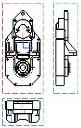
14 Part Drawing In this first section of the Getting Started tutorial, you will learn how to generate various types of views from a part, on the drawing sheet you previously defined. You can also go directly to the second section of the tutorial and learn about assembly drawings. Opening a Part Creating a Front View Creating a Projection View Creating a Section View Creating a Detail View Creating a Section Cut At the end of this tutorial, you will be able to print the following sheet:
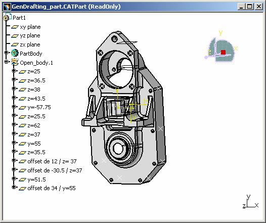
15 Opening a Part This task will show you how to open the 3D part from which you will create views in the Generative Drafting workbench. Note that you may create views from both 3D parts and assemblies. Refer to the Assembly Drawing section of this tutorial for information on how to use assemblies. 1. Select File ->Open... from the menu bar, or click the Open icon from the Standard toolbar. The File Selection dialog box appears. 2. Select the part to be opened, the GenDrafting_part.CATPart document. Note that this sample documents is to be found in the C:\Program Files\Dassault Systemes\Bxxdoc\English\online\cfysa\samples\Drafting folder (where xx in Bxxdoc stands for the current release number). 3. Click Open. The part is opened and a message appears, informing you that it is read-only. Simply close it. The part will remain displayed in the window, whatever views you create from it.
16
17 Creating a Front View This task will show you how to create a front view on the sheet you defined, from the 3D part you opened. At this step, it will be more convenient if you tile the drawing and the part windows horizontally. To do this, click Window -> Tile Horizontally from the menu bar. In the Generative Drafting workbench, the view name, scaling factor and view frame are set by default in views. Throughout this section of the Getting Started, we decided not to display view names and scaling factors. To deactivate them, go to Tools -> Options -> Mechanical Design -> Drafting, click on the Layout tab and un-check the View name and Scaling factor options. You can also specify what geometrical and dress-up elements should be generated on views, such as axes, center lines, fillets, 3D points, etc. Still in Tools -> Options -> Mechanical Design -> Drafting, click on the View tab and choose your options in Geometry generation / Dress-up. For example, check Generate center lines, and un-check Generate fillet. If you do not want to have the specification tree displayed, press the F3 key. 1. Click the drawing window to activate it. 2. Click the Front View icon from the Views toolbar (Projections sub-toolbar). 3. Now, in the part window, select the desired planar surface of the 3D part.


18 On the sheet, a blue knob appears, as well as a green frame containing a preview of the view to be created. The knob lets you define the location and orientation of the view to be created, using the blue manipulators: top, bottom, left, right or rotated according to a given snapping, or according to a specified rotation angle. 4. Click on the drawing sheet or at the center of the blue knob to generate the view.

19 A progress bar appears temporarily, showing the view creation progress. The front view is created.

20 Creating a Projection View This task will show you how to create projection views on the sheet. 1. Click the Projection View icon from the Views toolbar (Projections sub-toolbar). A preview of the view to be created appears. By default, the projection view is aligned to the front view. As you move the cursor, a preview of the view to be created appears, as long as you keep the cursor positioned at a possible projection view location (at the left, right, top or bottom of the red frame). 2. Define the projection view position, for example the right view position, using the cursor.


21 Note that the left view shown here was created and therefore positioned according to ISO standards and the First Angle Projection method. For more information, refer to Creating Views via the Wizard. 3. Click to generate the view. A progress bar appears while the view is being created. 4. Click the Projection View icon once again. 5. Use the cursor to define the projection view position, for example the bottom view position, and click to generate the view. Once again, a progress bar appears during the view creation process. The views result as shown here.
22

. 2. Select the holes and points to define the cutting profile on the view.")
23 Creating a Section View This task will show you how to create a section view using the front view you previously generated. Section views make drawings more readable by replacing the hidden elements of parts, including holes, with filled areas. To perform this scenario, it is recommended that you tile the drawing and the part windows horizontally. 1. In the drawing window, click the Offset Section View icon from the Views toolbar (Sections sub-toolbar). 2. Select the holes and points to define the cutting profile on the view. SmartPick assists you when creating the profile. Note that selecting a circular edge, a linear edge, an axis line or a center line (for example, a hole) makes the view callout associative by default to the corresponding 3D feature. If you select a circle, the callout will go through the circle center. If you select an edge, the callout will be parallel to the selected edge.


24 If you are not satisfied with the profile you create, you can, at any time, use the Undo or Redo icons. As you select the second point, the section plane appears and moves dynamically on the 3D part while you define the profile on the drawing. This section plane will automatically disappear when you double-click to end the callout definition.


25 3. Double-click to end the cutting profile creation. A preview is displayed. 4. Define the section view position using the cursor.


26 Positioning the view also defines the section view direction, as if it were a left or a right projection view. The direction of the callout blue arrows changes as you change the cursor position. 5. Click to generate the view. A progress bar appears while the view is being created. Using the cursor, you can then position the section view in order to align it, or to not align it, to the front view.
27 The patterns which are used to represent sections are defined in the standards. For more information, refer to Pattern Definition in the Interactive Drafting User's Guide. You may modify the pattern (hatching, dotting, coloring or motif). For more information, refer to Modifying a Pattern.
. 2.")

28 Creating a Detail View This task will show you how to create a detail view from the front view you previously generated. 1. Click the Detail View icon from the Views toolbar (Details sub-toolbar). 2. Click where you want to position the callout center. 3. Drag the cursor to define the callout radius, and click when you are satisfied. A dashed, blue circle appears at the position of the cursor. 4. Move this circle to where you want to position the detail view, and click to generate the view.

29 A progress bar appears while the view is being created. 5. If you are not satisfied with the position of the detail view, you can drag it to a new position.

30 Simply drop it to its new position.
31 As in step 4, the scale is, by default, twice that of the active view. You can modify this scale. 6. To do so, right-click the detail view, select Properties from the contextual menu and then click the View tab. 7. Enter 4 in the Scale field and click OK.
32 For the purpose of this exercise, you will now add a dimension to the detail view. 8. To do so, click the Dimension icon from the Dimensioning toolbar. 9. Click two elements in the view, as shown here. The dimension is created:
33
34 Creating a Section Cut This task will show you how to create a section cut from the detail view you just created. The scale of the section cut will depend on the scale of the view this section cut is generated from. In this case, the section cut is generated from a detail view with a scale 4, so the section cut scale will also be Right-click the detail view and select the Activate View option from the contextual menu. 2. Click the Aligned Section Cut icon from the Views toolbar (Sections sub-toolbar). 3. Select the holes and points to define the cutting profile. Note that selecting a circular edge, a linear edge, an axis line or a center line (for example, a hole) makes the cutting profile associative by default to the 3D feature. If you select a circle, the profile will go through the circle center. If you select an edge, the profile will be parallel to the selected edge.
35 Also note that SmartPick assists you when creating the profile. For more information, refer to Using SmartPick.
36 If you are not satisfied with the profile you create, you can, at any time, use the Undo or Redo icons. 4. Double-click to end the cutting profile creation. A preview of the view to be created appears. Positioning the section cut either to the right or to the left defines the section cut direction (as if it were a projection view). 5. Click to generate the section cut. A progress bar appears while the view is being created.
37 Once the section cut has been generated, you can modify its position relatively to the detail view: right-click the section cut and select View Positioning -> Position Independently of Reference View from the contextual menu. Selecting an existing edge within the view lets you define automatically the direction of the cutting profile. You can also select a reference plane in 3D or a 3D wireframe plane. For more information, refer to Creating an Offset Section Cut/Section View. The patterns which are used to represent the section cut are defined in the standards. For more information, refer to Pattern Definition in the Interactive Drafting User's Guide. For the purpose of this tutorial, you will now add a dimension to the section cut. 6. To add a diameter dimension to the section cut, click the Dimension icon and click one edge only. In our example, a larger font size has been applied to the dimension value. The resulting sheet now appears similar to what is shown here. Note that in this case, we repositioned the views.
38 7. You can now print this sheet. To do so, select File -> Print from the menu bar. Make sure the print format you set when defining the sheet is the same as the print format of the printer. You have reached the end of the first section of this tutorial. Now that you have learned about part drawings, you can go to the second section of this tutorial and learn about assembly drawings.
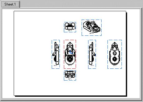
39 Assembly Drawing In this second section of the Getting Started tutorial, you will learn how to generate views from an assembly, on the drawing sheet you previously defined. Additionally, you will learn how to use other generative functionalities. You can also go back to the first section of the tutorial and learn about part drawings. Opening an Assembly Creating a Frame and a Title Block Creating Views via the Wizard Creating a Section View Overloading Element Properties Generating Balloons and a Bill of Material Creating an Isometric View and Changing its Properties At the end of this tutorial, you will be able to print the following sheet:
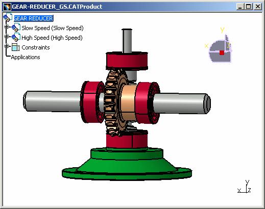
40 Opening an Assembly This task will show you how to open the 3D assembly from which you will create views in the Generative Drafting workbench, as well as perform other operations. Note that you may create views from both 3D assemblies and parts. Refer to the Part Drawing section of this tutorial for information on how to use parts. 1. Select File -> Open... from the menu bar, or click the Open icon from the Standard toolbar. The File Selection dialog box appears. 2. Select the assembly to be opened, the GEAR-REDUCER_GS.CATProduct document. Note that this sample documents is to be found in the C:\Program Files\Dassault Systemes\Bxxdoc\English\online\cfysa\samples\Drafting folder (where xx in Bxxdoc stands for the current release number). 3. Click Open. The assembly is opened and a message appears, informing you that it is read-only. Simply close it. The assembly will remain displayed in the window, whatever views you create from it.
41
42 Creating a Frame and a Title Block This task will show you how to insert a frame and a title block in the background of the sheet you defined. If you do not want to have the specification tree displayed, press the F3 key. 1. Click the drawing window to activate it. 2. Select Edit -> Background from the menu bar to switch to the background. 3. Click the Frame Creation icon from the Drawing toolbar. The Insert Frame and Title Block dialog box is displayed:
43 4. Choose a style from the Style of Titleblock drop-down list. For the purpose of this exercise, choose Drawing_Titleblock_Sample1. You can notice that a preview of the frame and title block is displayed in the dialog box. 5. Click the action you want to perform from the list of actions; in this case, click Creation. 6. Click OK. Wait while the frame and title block are being created. 7. Select Edit -> Working Views from the menu bar to switch back to the working views.
44 Creating Views via the Wizard This task will show you how to create a number of views on the sheet you defined, from the 3D assembly you opened. At this step, it will be more convenient if you tile the drawing and the assembly windows horizontally. To do this, click Window -> Tile Horizontally from the menu bar. If you performed the Part Drawing section of the Getting Started, you deactivated the view name and scaling factor (they are set by default). You now need to reactivate them so that they are displayed in views. To do this, go to Tools -> Options -> Mechanical Design -> Drafting, click on the Layout tab and check the View name and Scaling factor options. Also, you need to specify what geometrical and dress-up elements should be generated on views. Still in Tools -> Options -> Mechanical Design -> Drafting, click on the View tab. Make sure Generate center lines is selected (it should be if you performed the Part Drawing section of the Getting Started) and check Generate axis. 1. Click the View Creation Wizard icon from the Views toolbar (Wizard sub-toolbar). The View Wizard (1/2): Predefined Configurations dialog box is displayed.
: Arranging the Configuration dialog box is now displayed with a new set of view buttons. 4. Simply click Finish to validate and exit the dialog box.")
45 2. Select the Configuration 3 using the 1st angle projection method icon to create a front, a top and a left view using the ISO standard/first angle projection method. 3. Click Next > to go to the second step of the wizard. The View Wizard (2/2): Arranging the Configuration dialog box is now displayed with a new set of view buttons. 4. Simply click Finish to validate and exit the dialog box. For more in-depth information on projection methods and the various possibilities offered by the wizard, refer to Creating Views via the Wizard in the User Tasks chapter. 5. Now, in the assembly window, select the Slow Speed sub-assembly from the specification tree. Note that you can also select the whole assembly.


46 6. Then, click on the desired plane on the 3D assembly to define the reference plane. On the sheet, a blue knob appears, as well as three green frames containing a preview of the views to be created. The knob lets you define the location and orientation of the views to be created, using the blue manipulators: top, bottom, left, right or rotated according to a given snapping, or according to a specified rotation angle. 7. Click on the drawing sheet or at the center of the blue knob to generate the views. A progress bar appears temporarily, showing the view creation progress. The front, top and left views of the selected sub-assembly are created.
47 You may need to move the views to position them properly on the drawing. To do this, simply drag the front view (i.e. the active view with a red frame) with the cursor and drop it when you are satisfied with the position of the views.
48 Creating a Section View This task will show you how to create a section view using a view you previously generated. Section views make drawings more readable by replacing the hidden elements of parts, including holes, with filled areas. 1. Double-click the view from which you want to create the section view, to activate it. In this particular case, double-click the left view. 2. In the drawing window, click the Offset Section View icon from the Views toolbar (Sections subtoolbar). 3. Select the axis line in the left view. Note that selecting this axis line makes the view callout associative by default to the corresponding 3D feature. The first point of the cutting profile is automatically created on the view. The section plane appears and moves dynamically on the 3D sub-assembly while you define the profile on the drawing.

49 4. Double-click the last point of the cutting profile to end its creation. The section plane automatically disappears, and a preview is displayed. 5. Define the section view position using the cursor. Positioning the view also defines the section view direction, as if it were a left or a right projection view. The direction of the callout blue arrows changes as you change the cursor position. 6. Click to generate the view. A progress bar appears while the view is being created.
50 In our example, the various parts use a material to which a specific pattern is associated. In this case, it is the pattern associated to this material which is used. For more information, refer to View Generation Definition in the Interactive Drafting User's Guide. You may modify the pattern (hatching, dotting, coloring or motif). For more information, refer to Modifying a Pattern.

 that you want to edit, in this case, the slow speed shaft and the two bearings.")
51 Overloading Element Properties This task will show you how to overload the properties of elements in the section view you created previously. A number of the properties that you can overload are originally defined as properties of the 3D product component in the Product Structure workbench. 1. Right-click the section view A-A. 2. In the contextual menu, select Section view A-A object -> Overload properties. The Characteristics dialog box is displayed. Select the elements (part instances) that you want to edit, in this case, the slow speed shaft and the two bearings. These elements are highlighted as you select them in the drawing, and listed in the dialog box. 3. In the dialog box, select Slow speed shaft as the first element to edit, and click the Edit button. The Editor dialog box is displayed.
52 4. Uncheck Cut in section views to specify that the 3D element should not be cut in the section view. 5. Click OK to validate and exit the dialog box. 6. Back in the Characteristics dialog box, select the two bearings elements to edit them simultaneously, and click the Edit button. 7. In the Editor dialog box, choose another color in the appropriate box of the Graphic Properties area. 8. Click OK to validate and exit the dialog box. In the Characteristics dialog box, you can notice that the listed characteristics have been updated for each element.

53 9. Click OK again. A dialog box is displayed while the view is being re-computed. The selected elements are updated in the view: the slow speed shaft is not cut anymore, and the bearings are displayed with a different color. For more in-depth information on overloading properties, refer to Overloading Element Properties in the User Tasks chapter.
54 Generating Balloons and a Bill of Material This task will show you how to do the following: generate balloons in the active view. Balloons correspond to references defined on the different components of an assembly. insert a Bill of Material into the active view. The Bill of Material provides information on the product element from which the view was generated. The left view, in which you will generate the balloons and the Bill of Material, should still be active from the previous task. If not, double-click it to activate it. Generating Balloons Note that the assembly components have previously been numbered in the Product Structure workbench using the Generate Numbering command. 1. Select the Generate Balloons icon on the Dimension Generation toolbar. The balloons are automatically generated onto the active view. Generating a Bill of Material For more in-depth information on Bills of Material, refer to Generating a Bill of Material in the User Tasks chapter. 2. Select Insert -> Generation -> Bill of Material. 3. Click on the drawing sheet to specify where the Bill of Material should be inserted. In this particular case, click at the bottom right of the top view. The Bill of Material is created.
55 You can zoom the drawing to take a closer look at the balloons and/or the Bill of Material.
, all views are created as exact views.")
56 Creating an Isometric View and Changing its Properties This task will show you how to do the following: create an isometric view. change the view properties to switch it to Raster mode, displaying shading with edges. Indeed, by default (i.e. as specified in Tools -> Options -> Mechanical Design -> Drafting -> View tab), all views are created as exact views. At this step, if the drawing and the assembly windows are not tiled anymore, it is recommended that you do so by clicking Window -> Tile Horizontally from the menu bar. Creating an Isometric View 1. Click the Isometric View icon from the Views toolbar (Projections sub-toolbar). 2. Now, in the assembly window, click on the desired plane on the 3D assembly to define the reference plane.
57 3. A green frame with the preview of the isometric view to be created, as well as blue manipulators, appear. These manipulators let you redefine the reference plane orientation of the view. For more information, refer to Before you begin in the User Tasks chapter. 6. Click to generate the view. A progress bar appears while the view is being created. 7. Optionally drag the view to position it as wanted on the drawing. Changing the View Properties 8. Right-click the isometric view and select Properties from the contextual menu. 9. On the View tab, check 3D Colors in the Dress-up area. 10. In the Generation Mode area, select Raster from the View generation mode drop-down list. 11. Click the Options button. The Generation Mode Options dialog box is displayed.


58 12. Select Shading with edges from the Mode drop-down list. 13. Click Close to exit the dialog box. 14. Back in the Properties dialog box, click OK to validate. A progress bar appears while your modifications are being taken into account. The view is now in Raster mode, displaying shading with edges. The resulting sheet now appears similar to what is shown here. Note that in this case, we repositioned the views for better results.
59 15. You can now print this sheet. To do so, select File -> Print from the menu bar. Make sure the print format you set when defining the sheet is the same as the print format of the printer. You have reached the end of the second section of this tutorial and you have learned about assembly drawings. You may go to the first section of this tutorial and learn about part drawings if you have not already.
60 User Tasks Basic Tasks Administration Tasks
61 Basic Tasks The Generative Drafting workbench provides a simple method to create and modify views on a predefined sheet. You may also add, modify and/or delete dress-up and 2D elements to these views. All this is performed on a sheet which may include a frame and a title block and will eventually be printed. Before you begin, we recommend you de-activate the Grid icon from the Tools toolbar. Drawing Management Sheets View Creation View update reporting View Modification Generative View Styles Dimension Generation Dimension Manipulation Technological Feature Dimensions Annotations Dress-Up Elements Properties Images Printing Interoperability File Export and Import
62 Drawing Management The Generative Drafting workbench lets you manage CATDrawing documents. Create a new drawing: create a CATDrawing document. Open a drawing: open a CATDrawing document. Edit drawing links: edit the links which exist from a CATDrawing document to an existing CATPart document, CATProduct document, sheet metal part or a.model V4/V5 document. Update drawings via the batch monitor: update a list of CATDrawing documents using the batch monitor.

63 Creating a New Drawing This task will show you how to create a new drawing with pre-defined views generated from a part. Open the GenDrafting_part.CATPart document. Make sure no drawing is already open. 1. From the menu bar, select Start -> Mechanical Design. 2. Select the Drafting workbench. The New Drawing Creation dialog box appears with information on views that can possibly be created, as well as information on the drawing standards. You can modify the drawing standards. For this, click the Modify button. The New Drawing Creation dialog box will not appear if you did not previously open a CATPart or a CATProduct document.

64 3. Select the views to be automatically created on your drawing from the New Drawing Creation dialog box, for example the Front, Bottom and Right icon. 4. Click OK. A progress bar appears while the views are being generated from the opened CATPart. If the color of the part is white and the Inherit 3D Colors option is checked in Tools -> Options -> Mechanical Design -> Drafting -> View tab, the generated views will result white and therefore not necessarily properly visualized. The resulting view position will depend on the CATPart you loaded before starting the Drafting workbench. In other words, the views will be positioned according to: a plane you possibly selected in the part. a planar surface you possibly selected in the part. xy coordinates, in case you did not open a CATPart beforehand. In this case, you will only be able to define the drawing standards via the New Drawing dialog box.

65 Opening a Drawing This task will show you how to open a CATDrawing document. For more details on opening documents, refer to the Infrastructure User's Guide. 1. Click the Open icon from the Standard toolbar, or select File -> Open. 2. Select the document to be opened. In this case, open GenDrafting_part.CATDrawing. The GenDrafting_part.CATDrawing document opens as shown below:
66

67 Editing Drawing Links This task will show you how to edit the links which exist from a CATDrawing document to an existing CATPart document. Use the same methodology for links to a CATProduct, a sheet metal part or a V4/V5.model document. There are two possibilities: Editing drawing links with the reference document loaded Editing drawing links with the reference document not loaded Editing drawing links with the reference document loaded Go to Tools -> Options -> General, click on the General tab, and make sure the Load referenced documents option is checked (this option is set by default). Then, click OK to validate. When opening a drawing, if the referenced CATPart does not exist, a message will appear, mentioning that the links could not be found or contain wrong information. 1. Open the GenDrafting_part_links.CATDrawing document. 2. Select Edit -> Links. The Links dialog box appears with the existing links between the CATDrawing and its related CATPart. In our example, this corresponds to links applied to the front, top and right views which are found and loaded (currently displayed in our session).

. Then, click OK to validate. 1.")
68 3. Click OK to validate and exit the dialog box. Editing drawing links with the reference document not loaded Go to Tools -> Options -> General, click on the General tab, and uncheck the Load referenced documents option (this option is set by default). Then, click OK to validate. 1. Open the GenDrafting_part.CATDrawing document.
.")
69 2. Select Edit -> Links. The Links dialog box appears, showing the existing links between the CATDrawing and its related CATPart. In this example, this corresponds to links applied to the front, rear, top, bottom, left, right and isometric views, which are found but not loaded (although currently displayed in our session). Note that when the reference document is not loaded, a number of commands can no longer be used, such as projection, dressup and dimension commands. You can still modify the graphic properties of the elements in the views. 3. You can perform the following operations: use the Load button to load parts (and parts only) that are not loaded. The status will change from "Document not loaded" to "Loaded" use the Replace button to replace the selected link with another one. This button opens the File Selection dialog box to let you navigate to the desired file. Once the element has been replaced, the new element name is displayed along with its status in the Links dialog box. use the Refresh button to update the links related to the document without having to close then re-open the Links panel. This is especially useful when trying to re-access pointed documents that are not found (for instance, after a network disconnection): in that case, clicking the Refresh button avoids you to re-select the Edit->Links... command to display an updated view of the links. Note that the Synchronize, Activate/Deactivate and Isolate are unavailable when editing a.catdrawing document's links. For more details: For information on the other capabilities available with the Links dialog box (such as selecting a feature and opening or changing the corresponding source (CATPart)), refer to Editing Document Links in the Infrastructure User's Guide. The Search Order capability allows you to solve links. For more details, see Infrastructure User's Guide.

70 Updating Drawings Via the Batch Monitor This task will show you how to update a list of CATDrawing documents. To do this, you will use the batch monitor. The batch monitor lets you create as many batch configurations as required, and follow the progress of an update. Updating drawings via the batch monitor will be particularly helpful if you need to update a great number of drawings (but do not need to visualize them while doing so), or drawings which require large CPU resources. For more details on using the batch monitor, refer to Using the Batch Monitor in the Infrastructure User's Guide. 1. Run the CATUTIL command, using one of the methods described in the Infrastructure User's Guide. For example, from a V5 session, choose Tools -> Utility. The batch monitor appears, listing available batches. At this point, you either need to define the batch parameters that will be used to launch drawing update (this is the case if this is the first time you are using the batch monitor for drawing update), or you can run the batch directly (this is the case if you already defined all the necessary data). Defining the batch parameters Defining the update batch parameters consists in selecting the files to update, optionally specifying the files for which you want to force the update, and indicating the directory where the updated files should be saved. 2. From the list of available batches, double-click UpdateBatch (you can also right-click UpdateBatch and select New parameters file). The UpdateBatch dialog box is displayed.
 which contains the files that you want to include, select these files, and click Open.")
71 3. Click the Choose Files button to select the files that you want to update by batch. A selection dialog box is displayed. 4. Browse to the directory (on your computer or on your network) which contains the files that you want to include, select these files, and click Open. The selected files are now listed in the UpdateBatch dialog box. 5. Repeat steps 3 and 4 if you want to include files from another directory. You can remove files from the list of the files to update. To do so, select the unwanted file and click the Remove Files button. 6. By default, the files which do not need to be updated will not be. However, you can decide to force the update for certain files, or for all of them. To do this, double-click on No in the Force Update colum for each file for which you want to force the update. The value is now set to Yes, which means the update will be forced. 7. Click the [...] button next to the Target field to select the directory in which you want the updated files to be saved. A dialog box is displayed. 8. Browse to the directory in which you want to save the updated files, select it and click OK. Your update batch parameters are now defined. Each time you run the update batch, updated files present in this target directory will be overwritten by the newly updated files. 9. Click the Save button to specify where you want to save your batch parameters. A dialog box is displayed. 10. Browse to the directory in which you want to save the batch parameters file, specify a file name in the appropriate field, and click Save. Your parameters are saved in an xml file. 11. You can now either click Run to run the batch immediately or click Cancel to close the UpdateBatch dialog box and run the batch later. For the purpose of this scenario, click Cancel. You can now exit the batch monitor. To play the scenario below, however, you will need to re-open the batch monitor.

72 Running the batch Once you have defined batch parameters in an xml file, you can run the batch. 2. From the list of available batches, right-click UpdateBatch and select Associate a parameters file. A selection dialog box is displayed. 3. Browse to the directory in which you previously saved the xml batch parameters file, select this file, and click Open to validate. 4. Access the Start tab which now displays the name and location of the file you just associated to the batch. 5. Right-click the batch and select Run. The batch execution starts. 6. During or after the batch execution, you can get more information on the process in the Processes tab: the batch name, the batch identification number, the status (in progress or ended) as well as the start and end time. When the batch execution is over, you can exit the batch monitor.
73 Sheets The Generative Drafting workbench provides a simple method for managing a sheet. A sheet contains: a working view, which supports the geometry directly created in the sheet. a background view, which is dedicated to frames and title blocks. interactive or generated views. Define a Drafting sheet: Define the sheet using commands and dialog boxes. Modify a Drafting sheet: Modify the sheet orientation using the Page Setup dialog box. Create a frame and title block: Create a background sheet and insert a frame and a title block into it using the Frame and Title Block dialog box. Insert an image into a frame and title block: Insert a.gif image into a title block. Manage a background view: Add to a sheet the background view (title block plus elements) from another drawing.
74 Defining a Sheet This task will show you how to define the sheet for a new CATDrawing document and, if needed, add more sheets. This task is divided into the following sub-sections: Defining a new sheet Adding a sheet Defining a new sheet 1. Click the New icon from the Standard toolbar or select File -> New... from the menu bar. 2. Select Drawing, and click OK. The New Drawing dialog box is displayed.
75 3. From the New Drawing dialog box, select the ISO standard, and the A0 ISO format. 4. Select the Landscape orientation. 5. Select the 1:1 scale, and then click OK. The sheet scale is a scaling factor which applies to all views in a given sheet. It does not determine the position of the views (or any other object) contained in the sheet. When the grid is displayed, the position of the view in the sheet is not determined by the grid, which only deals with what is drawn directly in the sheet. To see the real position of a given view in a sheet, you need to use the ruler. It is the only way to see the real coordinates in a sheet referential. The sheet size depends on the standard type. For example, if you choose the ISO standard, the sheet will automatically be assigned the A0 format. You can choose another format if you want. At any time, you can change the standard (which you can update), sheet format, orientation and/or scale. To do this, select File -> Page Setup from the menu bar. If you select a new standard, the value in the Apply on field becomes All sheets and the new standard is applied to all drawing sheets. Adding a sheet You can add new sheets at any time. These new sheets will be assigned the same standard, format and orientation as the sheet first created and defined using the New Drawing dialog (default setting). 6. Click the New Sheet icon from the Drawing toolbar. The new sheet automatically appears as follows:
76 If you now delete Sheet.1, the newly created sheets will keep the same name. In other words, even if Sheet.1 has been deleted, Sheet.2 will remain named Sheet.2. The F3 key lets you show/hide the specification tree. Once you have created more than one sheet, you can activate one of the sheets by selecting it from the Drafting window or from the specification tree.

77 Modifying a Sheet This task will show you how to modify the standard, format, orientation and/or scale of a sheet. Doing this amounts to modifying the options you selected in the New Drawing dialog box when defining the sheet. Create a sheet using the ISO standard, the A0 ISO format, and the Landscape orientation. 1. Select File -> Page Setup from the menu bar. 2. From the Page Setup dialog box, select the ANSI standard, and the A ANSI format. You can update the current standards by clicking the Update button. This copies the most recent version of the standard file in the drawing, thus reflecting the latest changes an administrator may have performed in the standard file. If no new standard file is available, the Update button is disabled.

78 3. Select the Portrait orientation, and then click OK. At this step, you can also insert a background view into the sheet you are currently modifying. For more information, refer to Managing a Background View. The Page Setup dialog box also let you modify the sheet format and set it to the printer format. For more information, refer to Printing a Document.
79 Creating a Frame and a Title Block This task shows you how to insert a frame and a title block in the background of a sheet. This operation is performed using a macro. A few macros are provided by default. You can customize frames and title blocks by either modifying the default macros (to add actions) or creating your own macros (to add specific formats). For more information on how to do this, refer to Creating a Frame and a Title Block in the Interactive Drafting User's Guide. Open the GenDrafting_part.CATDrawing document. 1. Select Edit -> Background from the menu bar. 2. Click the Frame Creation icon from the Drawing toolbar. OR 2. Select the Insert -> Drawing -> Frame and Title Block items from the menu bar. The Insert Frame and Title Block dialog box is displayed:
80 3. Choose a macro from the Style of Titleblock drop-down list. For the purpose of this exercise, choose Drawing_Titleblock_Sample1. A preview of the frame and title block is displayed in the dialog box. 4. Indicate the action you want to perform in the Action list. Creation: creates the frame and the title block Deletion: deletes the frame and the title block Resizing: resizes and updates the frame and the title block (if you change the page format in File -> Page Setup) Update: updates the frame and title block, as well as the fields in the title block (partrelated and sheet-related information) CheckedBy: completes the "Checked by" field and automatically update the verification date AddRevisionBlock: adds a revision block Information which is not available in the part will be substituted by "XXX" in the drawing. 5. Click OK in the Insert Frame and Title Block dialog box.

81 When the Frame Creation icon is activated, you cannot edit the views. Use Edit -> Working Views when you need to work on views. When adding sheets, if you want the frame and title block to appear in newly created sheets, go to Tools -> Options -> Mechanical Design -> Drafting -> Layout tab. Check the Copy background view option and the First sheet option. This will insert the frame and title block from the sheet you previously created on the current drawing.
. 1. Select Insert -> Object from the menu bar. The Insert Object dialog box appears.")
82 Inserting an Image Into a Frame and Title Block This task will show you how to insert a.gif image into a frame and title block. Open the GenDrafting_part_titleblock_insert.CATDrawing document. Make sure you are in the background view (go to Edit -> Background from the menu bar). 1. Select Insert -> Object from the menu bar. The Insert Object dialog box appears. You can either create a new object or re-use an existing file. 2. Activate the Create from File option from the Insert Object dialog box.
83 3. Browse your disk and select a.gif image from the Insert Object dialog box. 4. Click OK to validate and exit the dialog box. 5. If needed, modify the position of the newly inserted object by dragging it with the cursor. Remember that you can modify the position as long as you remain in the background view. You can get something like this, for example: To go back to the working views and create a front view, for example, go to Edit -> Working views before clicking the Front View icon. If you want the frame and title block to appear in the newly created sheets when adding sheets, go to Tools -> Options -> Mechanical Design -> Drafting -> Layout tab. Check the Copy background view option and the First sheet option. This will insert the frame and title block from the sheet you previously created on the current drawing. If you have a viewer installed with the gif type associated to the viewer, you will not visualize the inserted image properly (an icon appears instead). If so, click on the displayed icon to get the image.
. 1. Select the Tools -> Options command to display the Options dialog box. 2.")
84 Managing a Background View This task will show you how to add to a sheet the background view (title block plus elements) from the sheet of another drawing. Before you begin, de-activate the Grid icon from the Tools toolbar (bottom right). 1. Select the Tools -> Options command to display the Options dialog box. 2. Click Mechanical Design -> Drafting -> Layout tab, and check the Copy background view and Other drawing options. If you un-check Copy background view, only the sheet properties will be copied from one sheet to another. If you check the First sheet and the Copy background view options, the background view of the first sheet will become the reference. If you check the Other drawing and the Copy background view options, the background view of the sheet you will select later will become the reference.

85 3. Click OK in the Options dialog box. 4. Click the New Sheet icon from the Drawing toolbar. The Insert Elements into a Sheet dialog box appears. 5. Click the Browse button in the Insert Elements into a Sheet dialog box. The File Selection dialog box appears. 6. Browse to select the drawing which you will use the background view from. In this particular case, select the GenDrafting_part_titleblock_insert.CATDrawing document. 7. Activate the Show Preview option in order to preview the selected CATDrawing document.

86 8. Click Open in the File Selection dialog box. The preview of the frame and title block of the selected CATDrawing is now displayed in the Insert Elements into a Sheet dialog box. At any time you can decide that you do not want the preview to appear. For this, de-activate the Preview On or Off button. 9. Click the Insert button. The title block now appears on a new sheet named Sheet 2.
87 Each time you need to insert a new sheet with a given frame and title block, go to Tools -> Options -> Mechanical Design -> Drafting -> Layout tab, and check the Copy background view option and the Other drawing option.
88 View Creation The Generative Drafting workbench provides a simple method to create views on a predefined sheet. In this chapter, most of the tasks illustrate how to create views from parts. These views can also be created from assemblies (exploded or not). Views created from assemblies are illustrated only whenever specific points need to be mentioned. Before you begin: You should be familiar with important concepts. Create a front view: Use a reference plane on the 3D part to create a front view. If needed, use the manipulator to assign the right position to the view. Create an advanced front view: Create advanced front views to configure such elements as the view name, view scale, etc. Whenever possible, a pertinent projection plane is automatically offered. Create projection views: Use the green frame to automatically generate the projection views as desired. Create an unfolded view: Create an unfolded view from a Sheet Metal part. Create a view from 3D: Generate a view and the associated annotations from the 3D. Create an auxiliary view: Define a plane that will be used to generate the auxiliary view. Create an offset section view: Use a cutting profile to define and position the offset section view. Create an offset section cut: Use a cutting profile to define and position the offset section cut. Create a section view (Planar Surface): Use a cutting profile to define and position the offset section view. Create a section cut (Planar Surface): Use a cutting profile to define and position the offset section view. Create an aligned section view: Use a cutting profile to define and position the aligned section view. Create an aligned section cut: Use a cutting profile to define and position the aligned section cut. Create a section view with profile defined in 3D: Create a section view using a 3D profile as cutting plane. Create a section cut with profile defined in 3D: Create a section cut using a 3D profile as cutting plane. Create a detail view: Use a callout to create a detail view via a boolean operator from the 3D. Create a detail view profile: Use a polygon to create a detail view via a boolean operator from the 3D. Create a quick detail view: Use a callout to create a detail view by computing the view directly from 2D projection.
89 Create a quick detail view profile: Use a polygon to create a detail view by computing the view directly from 2D projection. Create a clipping view: Create a clipping view with a circle as callout. Create a clipping view profile: Create a clipping view with a sketched profile as callout. Create an isometric view: Create an isometric view using a 3D part. Generate an exploded view: Create an isometric view, and then, projected views from an assembly previously exploded via Digital Mock-up workbench (DMU Navigator). Create a broken view: Create a broken view from an active and up to date generative view using two profiles corresponding to the part to be broken from the view extremities. Create a breakout view: Remove locally material from a left generated view, in order to visualize the remaining visible internal part. Create views via the wizard: Create views using a wizard by defining options in the Pre-Defined Configurations dialog box. Create views via the wizard: Automatically create front, bottom and right views using a wizard. Create views via the wizard: Automatically create front, left and top views using a wizard. Create views via the wizard: Automatically create all the views using a wizard.
90 Before You Begin Before you start creating views, this section provides you with information on the following topics: What is the active view? Defining the view orientation Generated geometry/dress-up settings Generated geometry/dress-up properties Constraints 2D/3D associativity 3D elements generated in views Dress-up generated in views Callout representation Note: Views as discussed in this section are created on a pre-defined sheet, and should not be confused with working views and background views, which are components of the sheet. For more information on these, refer to Sheets. What is the Active View? The active view is the view from which other views will be generated. This is also the view in which all the modifications will be performed. For instance, all the 2D geometry and dress-up elements that will be added to the draft views to be created. Open the GenDrafting_part.CATDrawing document. The active view is framed in red. Non-active views are framed in blue. When you create a view, until you click at the desired view location, the view to be created is framed in green. If you click this view, it becomes the active view and is framed in red. The active view is underlined in the Drafting specification tree, and specific icons are used to represent the view type (Front view, Projection view, Isometric view, etc). Refer to CATDrawing Specification Tree Icons for more information.


91 Activating a view 1. Double-click the frame of the view you want to activate. OR 1. Right-click the view you want to activate. The contextual menu appears. 2. Select Activate View. Axes are taken into account on active views. As a result, the frame of an active view will adapt to the elements included in this view. Defining the View Orientation You can redefine the reference plane orientation of a view to be created using the available blue arrows. This is the case when generating a front view, an isometric view or when generating views using the wizard. Open the GenDrafting_part.CATPart document and start creating a front view. 1. Start creating the view. 2. Click the right or left arrow to visualize the right or left side, respectively. 3. Click the bottom arrow to visualize the bottom side.


92 4. Click the counterclockwise arrow to rotate the reference plane. 5. Drag the green knob to redefine the rotating angle. The default increment value is 30 degrees. 6. You can modify the increment value using the green knob contextual menu. To do this, right-click on the knob and select the desired option from the contextual menu. Free hand rotation: Rotation is not snapped to a given increment but totally free. Incremental hand rotation: This is the default value: the rotation is snapped to a given increment (from 30 to 30 degrees, between zero and 330). Set increment...: The Increment Setting dialog box is displayed. Enter the Increment value you need. For example 5 deg (5 degrees). Set current angle to: If you select the Set angle value... option, the Angle Setting dialog box appears.

93 Enter the current angle (deg) you need. For example, 30. Remember that there is no associativity between the selected plane/face in the 3D part and the projection plane of the generated views. Yet, you can modify the view projection plane if you change the 3D part orientation. For more information, refer to the Modifying the View Projection Plane section. Generated Geometry/Dress-Up Settings You can generate a number of geometry or dress-up elements, depending on the options you select in Tools -> Options -> Mechanical Design -> Drafting -> View tab. For example, if you want the colors of a part to be automatically generated onto the views, check the Inherit 3D colors option. If the color of the part is white and the Inherit 3D colors option is checked, the generated views will be white and you may not be able to visualize them properly. Note that if you modify the graphical properties (color, line type, line thickness, layer) of generated geometry or dress-up elements, such modifications are associative, i.e. they are kept when updating the view later on. Also note that once you have overloaded the original properties of a geometry or a dress-up element, you cannot reset it to its original properties. Note that threads are generated on the condition they are defined on 3D holes. To project sketches, you need to select the Project 3D wireframe option. However, note that a sketch cannot be projected if it is currently being edited in the Sketcher workbench. To project sketches, you need to exit the Sketcher workbench before launching the view creation. Generated Geometry/Dress-Up Properties You can change the properties of some geometry and dress-up elements after the view has been generated, provided you check the desired options from the Properties dialog box. To display it, choose Properties from the contextual menu and select the View tab. The graphical properties of generated geometry and dress-up elements are kept after you update views. This is also true if you delete one or more elements. Note that if you modify the graphical properties (color, line type, line thickness, layer) of generated geometry or dress-up elements, such modifications are associative, i.e. they are kept when updating the view later on. Also note that once you have overloaded the original properties of a geometry or a dress-up element, you cannot reset it to its original properties. But this is true only for exact views. As far as layers are concerned, when you select a layer and modify the graphic properties of some elements, the properties will be applied only when you update the selected layer. By default, the view and its elements are created in the layer None, as displayed in the Graphic Properties Toolbar. Yet, if you modify your view and add elements, they will be created in the active layer, which can be layer 0, 1, 2 or any layer you select in the toolbar. Since generated items are deleted and recreated each time the view is updated, when edited, the graphical properties of the item are stored according to its 3D origin. This way, the right properties are applied to each new item according to its 3D origins. Thus, once updated, the generated item inherits the graphical properties corresponding to the 3D origin previously stored. In the following example, two generated items are modified. After performing an update, four items inherits the graphical properties of the 3D origin.
94 3D part. Modified Generated Item. Generated item with the same 3D origin. 3D part. Modified Generated Item. Generated item with the same 3D origin. Definition of Generated geometry and dress-up properties Views Front view Unfolded view View from 3D Isometric view Projection view Auxiliary view Section view Section cut Parameters Advanced front view Detail view Hidden lines Center lines Axis lines Threads Fillets Properties defined via Tools -> Options -> Mechanical Design -> Drafting -> View. Properties generated in the view. 3D colors
95 3D specifications 3D points 3D wireframe Properties defined via Tools -> Options -> Mechanical Design -> Drafting -> View. Properties defined via Tools -> Options -> Mechanical Design -> Drafting -> View. Generation mode Constraints Constraints detected when views are generated from the 3D do not appear on the drawing. 2D/3D Associativity... On Views A generative view results from specifications in a 3D document. This specification corresponds either to the whole document or to a feature in the document. This feature can be: 1. a.model document 2. a part document (the whole document or still one or more bodies) 3. a product document (the whole document or still one or more assemblies)... And View Positioning Generative views are positioned according to the center of gravity of the 3D part. If you modify a 3D part in such a way that the center of gravity of the part changes, then, when updating the view, the position of the view will be re-computed according to the new center of gravity of the part and will be modified accordingly. For more information on View Positioning properties, refer to the Generative Views Positioning Mode section in the Interactive Drafting User's Guide.... And Update Any modification applied to the specifications, before the generated view(s) is/are updated, is detected. You can perform an update. You can update all views or a selection of views: The Update icon is active in the Update toolbar when a sheet (or drawing) contains views that need to be updated (this can be all views in the sheet or some of them only). You can update all views in the active sheet by clicking this icon. An update symbol appears in the specification tree for the views that need to be updated. You can update a selection of views by selecting and right-clicking the view(s) you want to update and choosing Update Selection from the contextual menu. Only the items you select are updated. Update symbols remain in the specification tree for the items that have not been updated, so you always know which items are up-to-date and which are not. Update symbols also appear in the specification tree to indicate drawings and sheets containing views that need to be updated. You can update all views in a given sheet (or in a selection of sheets), by selecting and right-clicking the sheet(s) and then choosing Update Selection. You can also use the same method for a drawing: this will update all sheets (and therefore all views) in the drawing. During an update process, a dialog box is displayed to show the progress of the update. When the update involves several views, a Cancel button is available in this dialog box. This allows you to interrupt the update. The view that is being processed at the time you click this button will be updated (i.e. the update of the current view will finish), and then the update will stop. The subsequent views will not be updated.
96 ... After Updating Use the following commands to update views: Click the Update icon to update all views in the active sheet. Select and right-click the views you want to update and choose Update Selection from the contextual menu to update a selection of views. Type C:Force Update to update the drawing in accordance with the 3D. Be careful when doing this, as you may loose manual modifications applied to the drawing. During view update, the following operations are performed: associative section/auxiliary view profiles are re-computed the geometry is re-generated any annotation/dimension/dress up element linked to the generated geometry is re-computed in the case of elements (one or more) that have been graphically modified or deleted, these modifications/deletions are preserved, on the condition the view was up-to-date when you deleted or modified it. Note that you can restore deleted elements at any time by selecting the Restore Deleted option from the contextual menu and then updating the view. You can either use the Update icon if you modified the 3D part, or key in C:Force Update if you did not modify the 3D part. If you delete a generated item and subsequently perform an update, all items that have the same 3D origin as the deleted item will not be generated. Likewise, if you transfer a generated item to No Show and subsequently perform an update, all items that have the same 3D origin as the item in No Show will be transferred to No Show.... On Generated Dimensions Generated dimensions are associative with the 3D part constraints on the condition you checked the Generation dimensions when updating the sheet option from the Options dialog box (Tools -> Options -> Mechanical Design -> Drafting -> Generation tab). Note that these dimensions will be re-generated in accordance with the other options checked/un-checked in the Options dialog box.... And Color When you refresh a generated view you have modified, the colors are re-generated with the geometrical information from the part, and you might obtain unexpected results. As an example, if you create this part...

97 ...and then modify an element in the following generated view, such as the color of line "a" as in this example:...then, when updating the generated view, lines a and b will be red: The reason is that the view is refreshed with the part information and a and b lines are considered as the intersection of two planes and not as two different elements of the generative view. Note that modifications performed on the graphical properties (color, line type, line thickness) of a generated geometrical element (as is the case in our example above) are associative, i.e. such modifications are kept when updating the view later on. Also note that once you have overloaded the original properties of an element, you cannot reset it to its original properties.... And Operations Performed on Parts Operations performed on parts, and that can be saved with the part itself (such as Show/No Show, Delete, Deactivate, Visualization Filters, etc.), are taken into account when generating the view. For example, if you swap a part body to invisible space (No Show), this body will not be represented on the generated view. If you then swap this part body to visible space (Show), you can update the corresponding views; this time, the body will be represented on the generated view.... And Part Infrastructure Settings Settings used for a given part, and that only have an impact on the current session but cannot be saved with the part itself (such as the Display in Geometry Area category of settings available via Tools > Options > Infrastructure > Part Infrastructure > Display), have no impact on how or whether the part will be represented on the generated view.
98 3D Elements Generated in Views 3D elements are handled differently depending on their type and on the type of view you are generating. Section cuts, section views, and breakout views All CATPart elements, as well as Exact Solid and Skin elements from.model documents are supported in exact mode. Projections, quick detail views, clipping views and broken views Exact mode All CATPart elements are supported. Exact Solid and Skin elements from.model documents are supported. CGR and raster mode All CATPart elements except wireframe and 3D points are supported. All elements from.model documents are supported. External MultiCAD components are supported. Dress-up generated in views You can automatically create centerlines, axislines and threads according to the following criteria: Center lines The view plane must be perpendicular to the rotation face axis. The representation of the rotation face in the view must exceed 180 degrees. Axis lines The view plane must be parallel to the rotation face axis. Rotation faces made out of fillets are not taken into account when generating axis lines. Threads (front view) The view plane must be perpendicular to the rotation face axis. The face should be a threaded hole or a thread. The representation of the rotation face in the view must exceed 180 degrees. Threads (side view) The view plane must be parallel to the rotation face axis. The face should be a threaded hole or a thread.
99 Callout Representation You can specify that the size of callout elements should not be dependent on the view scale. You have two ways of doing this: After callout creation, right-click on the callout, select Properties in the contextual menu and check Size not dependent on view scale on the Callout tab. or Before callout creation, in Tools -> Options -> Mechanical Design -> Drafting -> Layout tab, check the Size not dependent on view scale option. This option will apply to newly created callouts, i.e. selecting this option will not have any impact on existing callouts. Note that this option only applies to drawings created with versions prior to V5 R11 (i.e. versions up to V5 R10).

100 Creating a Front View This task will show you how to create a front view either from a part or from the sub-part of a product. You will use a reference plane. You will also learn how to create a front view with local axis system, and how to create a front view from specific sub-bodies/sub-products. A front view is a projection view obtained by drawing perpendiculars from all points on the edges of the part to the plane of projection. The plane of projection upon which the front view is projected is called the frontal plane. Creating a front view Open the GenDrafting_part.CATPart document. Define a new drawing sheet. 1. Click the Front View icon from the Views toolbar. 2. Select one plane of the 3D part or a plane surface, to define the reference plane. Blue arrows appear. If you select a plane surface, the reference orientation will be the external normal of the planar surface.

101 To define the reference plane, you can also select: Two edges: these edges correspond to both axes defining the reference plane according to which the front view will be generated. The first edge determines the horizontal axis. A point and an edge, or three points: you will thus define a plane. In other words, you will select, in the geometry, one of the followings: a plane a point and then an edge an edge and then a point two edges two points and then an edge three points Note that you can redefine the projection plane using the arrows at any time before the view generation. 3. Click inside the sheet to generate the view. Right-click the frame of the view, select the Properties option from the contextual menu, View tab and check the required options in the Properties dialog box. By default, the axis and center lines are generated. You can also view hidden lines, threads, fillets, project 3D points, etc. In the case of an assembly view, you can insert Bill of Material information into the active view. In a Product Structure context, if you create a front view from a scene of a product, you can directly select the Scene object in the specification tree. You do not necessarily need to select the Product and sub-products any more.

102 Creating a front view with a local axis system This functionality allows you to take into account a local axis system when creating a view. That way, the origin of the generated view is the projection of the origin of the local axis system selected in the view plane. Open the Axisprojection.CATPart document. Define a new drawing sheet. 1. Select the drawing to activate it and click the Front View icon from the Views toolbar. 2. In the Part tree, select the local axis system, i.e. Axis System.1. Remember that you have to select the axis sytem in the specification tree and not in the 3D part. Otherwise it would be like selecting a line in the 3D part instead of the axis system.

103 3. Select one plane of the 3D part or a plane surface, to define the reference plane. 4. Click in the drawing to end the view creation. The part local axis system appears in the view.
104 When creating views with a local axis system, only the origin of the axis system is taken into account and respected in the generated view. The orientation is not taken into account. Create a front view from specific sub-bodies/subproducts You can multi-select specific sub-products in a product and/or several sub-bodies in a part to create front views displaying the selected elements only. These multi-selected 3D elements will be previewed and then used as reference planes for generating several front views. Open the Product_Balloon.CATProduct document. Double-click Scene1 at the down left of the screen. 1. Click the Front View icon from the Views toolbar. 2. Select one body or press the Ctrl key and then multi-select the desired elements in the specification tree.
105

106 3. In the 3D, point to the geometry to choose a projection plane. As you go over the geometry with the cursor, the oriented preview automatically appears on the 3D document.
, you can preview and then select the plane corresponding to this highlighted element.")
107 Be careful: once you multi-select bodies or sub-products, and go further into the procedure, you cannot select or de-select any more bodies or sub-products. As you highlight a 3D element (going over it with the cursor), you can preview and then select the plane corresponding to this highlighted element. As you highlight and select one or more elements defining the final plane, you can preview and assign a given orientation to this final plane. Once you defined the plane, you can preview the front view within the 3D document. Note that once an element is selected, this element becomes gray colored. In addition, you can only work in one 3D document. If you try selecting another document, you automatically leave the Front View command.

108 4. When the oriented preview corresponds to the projection plane you want, click on the plane to validate. The front view is previewed. At this point, you can still modify its orientation: 5. Click on the drawing to generate the view.
109 Creating a front view using selection sets You can also use selection sets to select the sub-bodies and/or sub-products from which you want to generate the front view. Selection sets let you gain in productivity, particularly in the case of large assemblies, when generating several views with numerous common features: you can select and store these features once and reuse the selection set as often as necessary without having to select the features again. Open the Product_Balloon.CATProduct document. 1. Before you start creating views from selection sets, you first need to create one or more selection sets for this product. For more information, refer to Storing Selections Using Selection in the Infrastructure User's Guide. For example, create a selection set to store the product screws. 2. Click the Front View icon from the Views toolbar.

110 3. Activate the CATProduct document and select Edit -> Selection Sets In the Selection Sets Selection dialog box that is displayed, select a selection set and click the Select button. The selection set items are highlighted in the 3D and in the specification tree. For more information, refer to Selecting Selection Sets in the Infrastructure User's Guide. Once you have selected a selection set, you can use the Ctrl key to select additional sub-bodies or sub-products. 5. In the 3D, point to the geometry to choose a projection plane. As you go over the geometry with the cursor, the oriented preview automatically appears on the 3D document.


111 6. When the oriented preview corresponds to the projection plane you want, click on the plane to validate. The front view is previewed. At this point, you can still modify its orientation: 7. Click on the drawing to generate the view.
112 You can also use selection sets when creating isometric views and advanced front views. Views created from selection sets are not associative with the selection sets themselves: if you modify a selection set after having created a view from it, the view will not be seen as needing an update, and if you do update the view, its definition will not change. You have to create the view over again in order for your modifications to be taken into account.

113 Creating an Advanced Front View This task will show you how to create an advanced front view. Creating advanced front views lets you configure such elements as the view name, view scale, etc. Whenever possible, a pertinent projection plane is automatically offered. For more information on front views in general, refer to Creating Front Views. Open the Pinmounting.CATPart document. Define a new drawing sheet. Activate the drawing by selecting the drawing window. 1. Click the Advanced Front View icon. A dialog box appears: 2. Name the view in the associated field:


114 3. Modify the scale value in 1:2 4. Click OK to validate your settings. 5. Select one plane of the 3D part or a plane surface, to define the reference plane. Blue arrows appear, you can still choose a plane and an orientation before view generation. 6. Click inside the sheet to generate the view. The DMU Space Analysis workbench lets you create section boxes in 3D. When generating advanced views from the DMU Space Analysis workbench, you can select this section box to generate a view displaying only the box content. If you then modify the section box in 3D, the view will be shown as needing an update in the drawing. If you destroy the section box in 3D, the box definition will remain in the drawing. For more information on section boxes, refer to Creating Section Boxes in the DMU Space Analysis User's Guide. You can use selection sets to generate advanced front views displaying a selection of elements only. Selection sets let you select the sub-bodies and/or sub-products from which the view will be generated. Refer to Creating a front view using selection sets for more information.
115 Creating a Projection View This task will show you how to create projection views on the sheet, relatively to the front view previously generated. Projection views are views conceived to be drawn or projected onto planes known as planes of projection. A transparent plane or pane of glass representing a plane of projection is located parallel to the front surfaces of the part. Open the GenDrafting_front_view.CATDrawing document. 1. Click the Drawing window, and double-click the Projection View icon from the Views toolbar (Projections sub-toolbar). As you move the cursor, a previewed projection view in a green frame appears on the sheet. 2. Define the projection view position by positioning the cursor at the desired view location, for example the right view position. 3. Click inside the green frame to generate the view.

116 Note that the right view above was created and therefore positioned according to the first projection method. Projection methods are described in Creating Views via the Wizard. 4. Define the bottom view position. 5. Click inside the sheet to generate the view. 6. Click on the Projection view icon to end the projection view creation.
117 To have information about generated geometry and dress-up properties, refer to Definition of Generated geometry and dress-up properties section.
118 Creating an Unfolded View This task shows how to create an unfolded view from a sheet metal part. An unfolded view is a projected view that is created from a sheet metal part in order to include in a section certain angled elements. As a result, the cutting plane may be bent so as to pass through those features. In other words, you will extract drawings from the SheetMetal Design or the Generative Sheetmetal Design workbench or the Aerospace SheetMetal Design workbench. For more information, refer to the appropriate user's guide. The Unfolded View command is active in the Generative Drafting workbench with a Version 5 SheetMetal Design, Generative Sheetmetal Design or Aerospace SheetMetal Design license. Open the GenDrafting_sheet_metal.CATPart document. Tile the windows horizontally to see both your drawing sheet and your sheet metal part at the same time. 1. From the Drafting workbench, click the Unfolded View icon from the Views toolbar (Projections sub-toolbar). 2. Select a surface on the part. This will automatically use the sheet metal reference wall plane. If you prefer to specify which plane should be used, select the plane in the Sheet Metal specification tree. 3. Click on the sheet. The unfolded view is displayed. It shows the axis lines resulting from bend axes, as well as bend limits. These axis lines and bend limits are represented as dashed lines. With sheet metal parts containing holes, the hole axes (center line) are also represented on the view.

119 The unfolded view looks like this:
120 4. Select one of the axis lines. Manipulators appear, allowing you to modify this line.
121 Creating a View from 3D This task shows how to generate views and the associated annotations from the 3D (Functional Tolerancing and Annotation workbench). A view from 3D is extracted from a 3D part, product or process that is assigned 3D tolerance specifications and annotations. The master document is the 3D part, product or process, which means that everything is handled at the 3D level: view definition (projection view, section view, section cut), annotation content and graphism. For this reason, it is recommended to perform modifications directly in 3D. You can generate the following types of view from 3D: projection views, section views, section cuts aligned section views, aligned section cuts, offset section views, offset section cuts Creating projection views, section views, section cuts Open the 3DViews.CATPart document. Tile the screen horizontally by selecting Window -> Tile Horizontally from the menu bar. In addition, make sure that the parent standard used in the CATDrawing document and in the CATPart (annotations) is the same. Otherwise, both the view and the annotations may not be generated. In our scenario, the parent standard used in the 3DViews.CATPart document is ISO. Therefore, the parent standard used in the CATDrawing document should be ISO. 1. Click the View From 3D icon from the Views toolbar (Projections sub-toolbar). 2. Select a view from the 3D, either in the specification tree or on the part. In this case, select Projected View.1 in the specification tree.

122 The view to be created is previewed (included annotations) on the sheet. You cannot modify the view orientation, but you can modify the view position by dragging it using the left mouse button. 3. Click on the sheet to create the new view. You can notice that one of the extracted annotations (datum B) bears a red cross mark, which indicates that the leader cannot be extracted linked to the geometry. This is because the 3D annotation leader is linked to 3D geometry which is not visible in the 2D view (i.e. hidden geometry). Such a red cross mark will be used for any annotation or dimension with a leader linked to hidden geometry (i.e. 3D geometry which is not visible in a 2D view). You can either change the properties of the view from 3D (Edit -> Properties) to display hidden lines, or transfer the marked annotations to a 3D view where the associated geometry will be visible when extracted.

123 4. Repeat the first two steps, this time selecting Projection View.2 as the view to be created. 5. Once again, repeat the first two steps, this time selecting Section Cut View.1. The preview is displayed on the sheet. 6. On the sheet, click Projection View.2 to specify that the callout for the section cut should be positioned in that view. Note that it works the same for section views. In views from 3D, the axis can only be that of the sheet: the H and V axis of the view must correspond to X and Y axis of the sheet. For this reason, the choice of the view in which to add a section cut callout is limited. In particular, the profile of the section cut must be horizontal on the chosen view. In the case of extraction views, the first line of the profile (i.e. corresponding to the first compounding view) must be horizontal. 7. Click on the sheet to create the view.

124 Creating aligned section views/section cuts and offset section views/section cuts Open the 3DViews_AlignedSectionView.CATPart document. Tile the screen horizontally by selecting Window -> Tile Horizontally from the menu bar. Make sure that the parent standard used in the CATDrawing document and in the CATPart (annotations) is the same. 1. Click the View From 3D icon from the Views toolbar (Projections sub-toolbar). 2. Select the aligned section view from the 3D, either in the specification tree or on the part. In this case, select Aligned Section View.1 in the specification tree. The view to be created is previewed (included annotations) on the sheet. You cannot modify the view orientation, but you can modify the view position by dragging it using the right mouse button. 3. Click on the sheet to create the new view.
125 More About Views from 3D Only the elements visualized in the 3D (i.e. in Show mode) at the time of extraction are extracted in the view from 3D. In other words, any element hidden in the 3D will not appear in the view. If you then show this element in the 3D part, it will be displayed in the view from 3D after you update it. You can move or modify annotations in views from 3D. However, if the part is modified and you subsequently update the view, any modification applied to the annotations in the drawing will be lost. We advise you perform modifications on the 3D part directly. Extracted annotations are not associative to the geometry. 2D annotations can be added to views from 3D. Views from 3D can be rotated. In other words, when you edit the properties of this view (Edit -> Properties), the Angle field can be edited and customized according to your needs. In views from 3D, the horizontal axis of the view is parallel to the horizontal axis of the sheet. You can create views from 3D from a part (Functional Tolerancing and Annotation workbench), a product (Product Functional Tolerancing and Annotation workbench) or a process (Process Tolerancing and Annotation workbench). It is currently impossible to extract views from part, product and process at once. However, you can superpose views as a bypass (using the View Positioning -> Superpose contextual command). Views from 3D are not associative to the geometry of the 3D view. So, if you modify the geometry of a 3D view, the definition of the corresponding 2D view will not be modified at the next update, even if the 3D view is associative to the geometry. The Note Object Attribute (NOA) from a ditto (2D component) is now extracted in views from 3D. However, some restrictions apply: If a frame is defined in 3D, this frame is not displayed in the 2D view. To work around this, do not use the 3D annotation frame when defining the NOA reference; instead, have your administrator define the frame as part of the 2D component geometry. Information regarding the documents used to create the ditto (drawing, parts, catalogs) will be lost. Hidden texts and URLs on flag notes and Note Object Attributes will be lost during extraction.

126 Creating an Auxiliary View This task will show you how to create an auxiliary view. Many objects are of such shape that their principal faces cannot always be assumed parallel to the regular planes of projection. Creating an auxiliary view allows showing the true shapes by assuming a direction of sight perpendicular to planes that are perpendicular of the curves. This auxiliary view, together with the top view, completely describes the object. Open the GenDrafting_part.CATDrawing document. Make sure the right view is active (doubleclick to activate it). 1. Click the Auxiliary View icon toolbar (Projections sub-toolbar). from the Views 2. Sketch the representation of the plane. In this case, click an edge on the right view. You could also click a point and then an edge. Both the 3D surface and the sketched plane are associative. The selected edge becomes a line that you can position where desired using the cursor. This line/callout will be automatically used as the plane.

127 3. Click to position the callout. The reference plane is automatically positioned according to the selected edge. Positioning the auxiliary view callout amounts to defining the auxiliary view direction. 4. Click to position the auxiliary view.. Before clicking, as you move the cursor within a zone perpendicular to the plane, a preview of the auxiliary view to be created simultaneously appears. This view will be automatically positioned accordingly. This is also true when creating a section view or a section cut. You can also move the cursor outside the zone perpendicular to the plane and position the view where you want. Note that the callout can be inverted or graphically modified.
128 You can move the view freely after it has been created, providing you position it independently of its reference view. For this: 1. Right-click the frame of the view you want to move. 2. Select the View Positioning -> Position Independently of Reference View from the displayed contextual menu. 3. Drag the view to the desired location. You can choose the auxiliary view axis orientation. For this go to Tools -> Options -> Mechanical Design -> Drafting -> Layout and check the Auxiliary and/or section views orientation according to profile option. To have information about generated geometry and dress-up properties, refer to Definition of Generated geometry and dress-up properties section.
129 Creating an Offset Section View / Cut This task will show you how to create an offset section view/cut using a cutting profile as cutting plane. In sectioning through irregular objects, it is often desirable to show several features that do not lie in a straight line by offsetting or bending the cutting plane. Open the GenDrafting_section_view02.CATDrawing and GenDrafting_section_view.CATDrawing documents. Make sure the front view is active (use double-clicking). Delete the text assigned to the front view (right-click on the text and select Delete option from the contextual menu). 1. Click the Drawing window, and click the Offset Section View icon or the Offset Section Cut icon from the Views toolbar (Sections sub-toolbar). 2. Select the elements required for sketching the cutting profile: points, edges (linear or circular), center lines, axes. If you are not satisfied with the profile you create, you can, at any time, use Undo or Redo icons. Note that SmartPick assists you when creating this profile. The section plane appears on the 3D part and moves dynamically on the part. Associativity between the 3D part and the generated section view is created when selecting edges, center lines and axes. Yet, constraints detected by SmartPick are not created. 3. Double-click to end the cutting profile creation. Offset section view Positioning the section view using the cursor amounts to defining the section view direction. The cutting profile is hole associative.


130 4. Click to define the section view direction and to position the view on the sheet. The view name and scale appear on the generated view as you checked the View name and Scaling factor options in the Options dialog box. Even when the view is generated, you can edit and modify the section profile. For this double-click this profile and either invert or replace it.


131 Offset Section Cut Positioning the section cut using the cursor amounts to defining the section cut direction. The cutting profile is hole associative. For the purpose of this scenario, select a circular edge and double-click when you are satisfied with the position of the rotating profile that automatically appears on the 3D view.
132 4. Click to define the section cut direction and to position the view on the sheet. The view name and scale appear on the generated view as you checked the View name and Scaling factor options in the Options dialog box. The frame of the active view adapts to the length of the cutting profile. You can insert Bill of Material information into the active view. You can assign a line type to the view to be generated. For this, go to Tools -> Options -> Mechanical Design -> Drafting -> View tab, click the Configure button next to View Linetype and select the desired option from the dialog box. Pattern The patterns which are used to represent the section are defined in the standards. For more information, refer to Pattern Definition in the Interactive Drafting User's Guide. You may modify the pattern (hatching, dotting, coloring or motif) by right-clicking the pattern and selecting Properties from the contextual menu. This will display the Properties dialog box in which you may either select a new pattern or modify some graphical attributes of the existing pattern. For more information, refer to Modifying a Pattern. Patterns will not be applied to offset sections which are tangent to 3D faces. Apply uncut specification In an assembly, you can define that given parts will or will not be sectioned when generated into section views or breakout views. In the Assembly Design workbench, select one part, then the Edit -> Properties command from the menu bar from and either activate or de-activate the Do not cut in section views options. To have information about generated geometry and dress-up properties, refer to Definition of Generated geometry and dress-up properties section.

133 Creating a Section View / Cut (Planar Surface) This task will show you how to create a section view / section cut using a planar surface or a wireframe plane in the 3D. A section view / section cut is a view that allows sectioning through irregular objects, and thereby allows showing several features that do not lie in a straight line by offsetting or bending the cutting plane. Open the GenDrafting_part.CATPart and the GenDrafting_front_view.CATDrawing documents. Make sure the front view is active on the drawing (double-click to activate it). Tile your windows vertically to see both your part and the related drawing. 1. Click the Drawing window, and click the Offset Section View icon or the Offset Section Cut icon from the Views toolbar (Sections sub-toolbar). 2. Select a planar surface on the 3D part. This planar surface need to be perpendicular to the projection plane of the active view. The section plane appears on the 3D part and moves dynamically on the part. The cutting profile is automatically displayed on the front view as well as a preview of the view to be generated.
134 3. Click to generate the view. The patterns which are used to represent the section are defined in the standards. For more information, refer to Pattern Definition in the Interactive Drafting User's Guide. You may modify the pattern (hatching, dotting, coloring or motif) by right-clicking the pattern and selecting Properties from the contextual menu. This will display the Properties dialog box in which you may either select a new pattern or modify some graphical attributes of the existing pattern. For more information, refer to Modifying a Pattern.
135 Creating an Aligned Section View / Cut This task will show you how to create an aligned section view and/or aligned section cut using a cutting profile as cutting plane. An aligned section view / cut is a view created from a cutting profile defined from non parallel planes. In order to include in a section certain angled elements, the cutting plane may be bent so as to pass through those features. The plane and feature are then imagined to be revolved into the original plane. Open the GenDrafting_aligned_view02.CATDrawing document. 1. Click the Drawing window, and click the Aligned Section Cut. If desired, you can also click the Aligned Section View icon from the Views toolbar (Sections sub-toolbar). 2. Select the elements required for sketching the cutting profile: points, edges (linear or circular), center lines, the axis. If you are not satisfied with the profile you create, you can, at any time, use Undo icons. Note that SmartPick assists you when creating this profile. or Redo


136 The section plane also appears on the 3D part and moves dynamically on the part. 3. Double-click to end the cutting profile creation. Positioning the section view amounts to defining the section cut direction. The cutting profile is hole associative.

137 4. Click to generate the view. The patterns which are used to represent the section are defined in the standards. For more information, refer to Pattern Definition in the Interactive Drafting User's Guide. You may modify the pattern (hatching, dotting, coloring or motif) by right-clicking the pattern and selecting Properties from the contextual menu. This will display the Properties dialog box in which you may either select a new pattern or modify some graphical attributes of the existing pattern. For more information, refer to Modifying a Pattern. Patterns will not be applied to aligned sections which are tangent to 3D faces.

138 Creating a Section View / Cut with Profile Defined in 3D In this task, you will learn how to create a section view or a section cut using a 3D profile as cutting plane. Section views / section cuts are usually created using a cutting profile as the cutting plane; such a profile is typically driven using concentricity or parallelism constraints. Defining a profile in 3D to create a section view / section cut enables you to make the profile associative with the geometry, and therefore to drive this profile using dimensional constraints, for example. Open the GenDrafting_part.CATPart and the GenDrafting_front_view.CATDrawing documents. Tile your windows vertically to see both your part and the related drawing. 1. In the Part window, click the Sketcher icon and select the xy plane as the reference plane. You are now in the Sketcher workbench. 2. Click the Profile icon and sketch the profile you will use as cutting plane. For the purpose of this exercise, make sure you sketch your profile using orthogonal lines.

139 3. You can now create dimensional constraints between your profile and other elements. Click the Constraint icon. 4. Now, click a vertical line and the edge of the part to create a dimensional constraint between them. 5. Exit the Sketcher workbench. 6. In the Drawing window, click the Update icon to update the view. 7. Click the Offset Section View icon from the Views toolbar (Sections sub-toolbar). Depending on the type of profile you sketched and on the type of section (offset or aligned) you want, you can select another icon on the Sections sub-toolbar. If the 3D profile is not valid for generating the appropriate view, you will not be able to select it. In this case, you will need to select another icon.

140 8. Select the profile on the 3D part. The cutting profile is automatically displayed on the front view as well as a preview of the view to be generated. Positioning the section view amounts to defining the section view or the section cut direction. 9. Click to generate the view. You can modify the section view / section cut by editing the 3D profile. After doing so, don't forget to update the drawing. When editing a 3D profile, make sure that you modify it in accordance with the type of section (offset or aligned) you created: if an edited profile is invalid when you update a drawing, the associated section view / section cut will not be displayed (an error symbol will appear instead). If you delete the 3D profile and then update the drawing, the section view / section cut will not be deleted. The profile will no longer be associated with the geometry. You can subsequently edit the profile directly in the drawing by double-clicking it. The patterns which are used to represent the section are defined in the standards. For more information, refer to Pattern Definition in the Interactive Drafting User's Guide. You may modify the pattern (hatching, dotting, coloring or motif) by right-clicking the pattern and selecting Properties from the contextual menu. This will display the Properties dialog box in which you may either select a new pattern or modify some graphical attributes of the existing
141 pattern. For more information, refer to Modifying a Pattern. Patterns will not be applied to aligned sections which are tangent to 3D faces.
142 Creating a Detail View / Detail View Profile This task will show you how to create from the 3D a detail view using either a circle as callout or a sketched profile. Note that the procedure varies slightly depending on the method you choose. A detail view is a partial generated view that shows only what is necessary in the clear description of the object. Note that the Detail view command uses a Boolean operator from the 3D whereas the Quick Detail view command computes the view directly from the 2D projection. The representation is therefore different. Open the GenDrafting_isometric_view.CATDrawing document. To create a detail view (this is the method illustrated here): 1. Click the Drawing window, and click the Detail View icon from the Views toolbar (Details sub-toolbar). 2. Click the callout center. 3. Drag to select the callout radius and click a point to terminate the selection. OR To create a detail view using a sketched profile: 1. Click the Drawing window, and click the Detail View Profile icon from the Views toolbar (Details sub-toolbar). 2. Create the points required for sketching a polygon used as profile. 3. Double click to end the cutting profile creation. SmartPick assist you when sketching the profile. You do not necessarily need to close the profile: the profile will automatically be closed.
143 The dress-up elements generated from the 3D are identified and represented in the generated detail view whereas it is not when generating quick detail views. 4. Click to generate the detail view. The default scale is 2 (twice the scale of the active view). You can modify this scale. 5. Right-click the detail view and select the Properties option from the contextual menu, View tab. Enter the desired Parameters Scale, for example 3 and then click OK in this Properties dialog box.
144 You can also modify the detail view boundary (Properties dialog box). You can assign a line type to the view to be generated. For this, go to Tools -> Options -> Mechanical Design -> Drafting -> View tab, click the Configure button next to View Linetype and select the desired option from the dialog box. In the isometric view, you can move the detail text ("A" in this example) after detail view creation. If you create a detail view from a section view and subsequently modify the cutting profile in the section view, in such a way that the detail view is no longer accurate, the detail view cannot be updated so as to take into account the changes in the cutting profile. If you create a broken view from a view which contains a detail view callout, the detail view callout will not be broken in the broken view. In other words, the circular shape of the callout will not be modified, even if the callout overlaps the break profile. As for the detail view, it will not modified by the break operation. To have information about generated geometry and dressup properties, refer to Definition of Generated geometry and dress-up properties section.
145 Creating a Quick Detail View / Quick Detail View Profile This task will show you how to quickly create a detail view using either a circle as callout or a sketched profile. In this particular case, we create a quick detail view using a sketched profile as we create this detail view from an oblong part. Note that for creating a detail view using a circle, the dialog is exactly the same. A detail view is a partial generated view that shows only what is necessary in the clear description of the object. Note that the Quick Detail view command computes the view directly from the 2D projection whereas the Detail view command uses a Boolean operator from the 3D. The representation is therefore different. As a result, if the view which defines the quick detail view profile is modified, then the quick detail view will be updated at the same time as the defining view. Open the GenDrafting_isometric_view.CATDrawing document. 1. Click the Drawing window and click the Quick Detail View Profile icon (Details sub-toolbar). from the Views toolbar If you create a detail view using a sketched profile, you will click the Quick Detail View icon. 2. Select the points required for sketching a polygon. 3. Double click to end the cutting profile creation. Note that you do not necessarily need to close the profile. If so, the profile will automatically be closed.
146 4. Click to generate the quick detail view. Unlike a detail view, the boundary is entirely closed. You can modify this detail view boundary (Properties dialog box). The default scale is 2 (twice the scale of the active view). You can modify this scale. For this, right-click the detail view and select the Properties option from the contextual menu, View tab. Enter the desired Parameters Scale and then click OK in this Properties dialog box. You can insert Bill of Material information into the active view.
147 You can assign a line type to the view to be generated. For this, go to Tools -> Options -> Mechanical Design -> Drafting -> View tab, click the Configure button next to View Linetype and select the desired option from the dialog box. To have information about generated geometry and dress-up properties, refer to Definition of Generated geometry and dress-up properties section.
148 Creating a Clipping View / Clipping View Profile This task will show you how to create a clipping view using a circle as callout. You can also use a roughly sketched profile. A clipping view is a partial view that shows only what is necessary in the clear description of the object. This operation is applied directly onto the active view. Open the GenDrafting_clipping_view.CATDrawing document. 1. Click the Drawing window, and click the Clipping View icon from the Views toolbar (Clippings sub-toolbar). If you create a clipping view using a sketched profile, you will select the Clipping View Profile icon. 2. Select the center of the circle, or select the required points for sketching a polygon if you are creating a clipping view using a sketched profile.
149 3. To end the clipping profile creation, release the mouse in the case of a circle, or double-click in the case of a polygon. The clipping view and the associated profile result as shown here:
150 When Put in now show dimension on non-visible geometry is activated in Tools->Options, the generated dimensions that are not in the clipping view and the annotations that are not linked to the generated clipping view anymore are automatically turned into the NoShow mode. If it is not activated, the dimension is displayed in the generated clipping view in light blue. A generative dimension does not turn into light blue. For more information, refer to the Dimension on geometry without 2D representation section in the Interactive Drafting User's Guide. 4. Click the Swap visible space icon from the View toolbar. You can now visualize the dimensions and annotations that do not appear on the clipping view anymore and, if needed, make them appear again on the clipping view. You can select the Unclip option from the contextual menu. However, selecting this option will not make the dimensions re-appear on the unclipped view.
151 5. Click the Hide/Show icon from the View toolbar. 6. Select the dimension you want to display on the clipping view. 7. Click the Swap visible space icon from the View toolbar. The selected dimension now appears on the clipping view again. You can insert Bill of Material information into the active view. Once a clipping has been applied onto a view, it is impossible to create detail views, breakout views and broken views from this view.
152 Creating an Isometric View This task will show you how to create an isometric view from a 3D part. The Isometric View command enables you to create a 2D view with any orientation, this orientation being the same as the one in the 3D viewer. Among other results, and depending on how the 3D viewer is oriented when you create the view, you can obtain a regular X-Y-Z isometric view. Isometric means "equal measure". To produce an isometric projection, it is necessary to place the object so that its principal edges make equal angles with the plane of projection and are therefore foreshortened equally. Note that an isometric view created from a product can be re-used for generating an exploded view. Open the GenDrafting_part02.CATPart document. Start creating a new drawing (and this case, create an empty sheet). Tile your windows vertically to visualize the 3D part and the sheet at the same time. In a Product Structure context, if you create a front view from a scene of a product, you can directly select the Scene object in the specification tree. You do not necessarily need to select the Product and sub-products. Scenes of products created with versions prior to V5R14 will be displayed as shown above. For any scene of products created in V5R14, the specification tree is updated as follows: 1. Click the Drawing window, and click the Isometric View icon from the Views toolbar (Projections sub-toolbar).

153 2. Define the 3D viewer orientation according to the result you want to obtain in the view. For this, you can either manipulate the viewer directly, or use the View > Named Views command in 3D to define your orientation precisely. Prior to defining your orientation, it may be useful to use different canonical points of view by defining the corresponding local axis systems in 3D. For more information, refer to Axis System in the Part Design User's Guide. 3. Click the 3D part. A green frame with the preview of the isometric view to be created, as well as blue manipulators, appear. You can re-define the reference plane orientation of the view to be created using these manipulators: to the bottom, the left, the right, the top, or rotated using a given snapping or according to an edited rotation angle. For more information, refer to Before you begin.

154 You can use selection sets to generate isometric views displaying a selection of elements only. Selection sets let you select the sub-bodies and/or sub-products from which the view will be generated. Refer to Creating a front view using selection sets for more information.
155 Creating an Exploded View This task will show you how to create an isometric view, and then, projected views from an assembly previously exploded via Digital Mock-up workbench (DMU Navigator). Open Gun_Body.CATProduct. 1. Go to the Digital Mock-up workbench (DMU Navigator) and define the Scene with the adequate orientation and with the instances properly positioned. Scenes of products created with versions prior to V5R14 will be displayed as shown above. For any scene of products created in V5R14, the specification tree is updated as follows: 2. Explode the view as shown here:
 either in the specification tree or in the geometry area, and then select a plane on the product. 5.")
156 3. Go to the Drafting workbench and click the Isometric View icon from the Views toolbar (Projections sub-toolbar). 4. Select the scene (Scene 1) either in the specification tree or in the geometry area, and then select a plane on the product. 5. Click in the drawing to position the resulting exploded view.
157 Non exploded product: Exploded product: You can insert Bill of Material information into the active view. Remember that you must select the scene before creating a view, otherwise you will create a view of the whole assembly.
158 Creating a Broken View This task will show you how create a broken view from an active and up-to-date generated view. You will define two profiles corresponding to the part to be broken from the view extremities. A broken view is a view that allows shortening an elongated object. Open the GenDrafting_part_Broken_View.CATDrawing document. 1. Click the Broken View icon from the Views toolbar. 2. Click a first point corresponding to the first extremity of the first profile. A green dotted profile appears which allows you to position the profile either vertically or horizontally. 3. Click a second point corresponding to the profile second extremity. In this example, click a point so that the profile appears horizontally. OR 3. Drag the cursor over the green horizontal profile that appears as you create a first point and, if needed, click to locate the second point on this first profile.
159 4. If needed, translate the profile. Red zones appear. These red zones correspond to the zones out of which the view cannot be broken. Note that the orientation of the second profile is the same as the orientation of the first profile. 5. Click a point for defining the position of the second green profile that appears. 6. Click on the sheet. The broken view appears. You can create new breaks in a broken view, but in the same direction and providing the two breaks do not overlap. You can remove created breaks via the contextual menu. It is impossible to create breakout views, offset section views, detail views and clipping views from a broken view. More on Broken Views Propagating a broken specification To propagate the broken specification during the creation of a projection or auxiliary view, go to Tools -> Options -> Drafting from the menu bar (Layout tab) and activate the Propagation of broken and breakout specifications option. Propagating a specification means generating a view (B) from another view (A) on which you previously performed an operation, and obtaining a view (B) which includes this operation. For example, (i) you create a broken view (view A) and activate the Propagation of broken and breakout specifications option, you then (ii) generate a projection view (view B). As a result, the projected view (view B) will appear with the broken area. You can only perform a propagation from a broken view if the projection direction is perpendicular to the direction of the broken view.
160 About line types You can assign a line type to the view to be generated. For this, go to Tools -> Options -> Mechanical Design -> Drafting -> View tab, click the Configure button next to View Linetype and select the desired option from the dialog box.
161 Creating a Breakout View This task will show you how to create a breakout view. In other words, you will remove locally material from a generated view in order to visualize the remaining visible internal part. A breakout view is one not in direct projection from the view containing the cutting profile. In other words, it is not positioned in agreement with the standard arrangement of views. A breakout view is often a partial section. Open the GenDrafting_part.CATDrawing document. For the purpose of this scenario, you will create the breakout on the left view: therefore, make sure the left view is active by double-clicking it. 1. Click the Drawing window, and click the Breakout View icon from the Views toolbar (Break View sub-toolbar). 2. Click the first point of the breakout profile. 3. Click as many points as desired for creating the profile. 4. If needed, double-click to end the profile creation and close this profile automatically. OR 4. Click on the profile first point to close and end the profile creation.
, provided the Animate option is checked.")

162 The 3D Viewer window appears, displaying the 3D part corresponding to the generated view. A green arrow indicates in which direction the breakout will be created. This window lets you position the 3D part according to a view you go over (on the drawing), provided the Animate option is checked. This window also lets you visualize a view plane and use it to define the depth of the breakout. You can move this plane using one of these methods: directly in the 3D Viewer window, drag the plane to the desired location. This method does not let you define the depth of the breakout precisely. The breakout will not be associative with any element. in the drawing, place the cursor over an axis, a center line or an edge (circular or linear) of a perpendicular view. The plane will be moved accordingly. This method lets you break the view through a hole or a face, for example. The breakout will be associative with the selected element. in the drawing, select the edge which corresponds to the face that you will use as a reference element to define the depth of the breakout, and enter the depth in the appropriate 3D Viewer field. This method lets you define the depth of the breakout precisely. The breakout will be associative with the selected reference element and with the depth value. 5. Check the Animate option to visualize the 3D part in accordance with the position of the cursor on a generated view. 6. In the CATDrawing document, place the cursor over the front view (which is perpendicular to the left view). 7. In the CATDrawing document, place the cursor over the center line that will be used as an extremity plane, as shown below.
163 OR 7. In the 3D Viewer window, click the Reference element field to select it. Then, in the CATDrawing document, select the edge which corresponds to the face that will be used as a reference element, and enter the breakout depth in the Depth (in mm) field (you can also define the depth by moving the red plane with the mouse). 8. Then, click OK in the 3D Viewer window. The breakout view is created.
164 You can create breakout views on: projection views, auxiliary views, section views a view that already contains breakouts. You cannot create breakout views on: section cuts, detail/ clipping views, broken views. To remove a breakout, do as follows: Once the breakout view is created, right-click the view, and select the Remove Breakout option. All the breakouts will be removed. or Right-click on the edge of a resulting breakout and select Generated item object, then Remove breakout. Only this breakout will be removed. Once created, the breakout view profile cannot be modified. You cannot apply a breakout and a break to the same view.
165 More on Breakout Views Manual propagation of a breakout specification Right-click the view, select the Apply Breakout To option and click another view you want to apply the breakout to. Automatic propagation of a breakout specification Propagating a specification means generating a view (B) from another view (A) on which you previously performed an operation and including this operation in the generated view (B). To generate views (projection, auxiliary, section, section cut and detail) from a breakout view, go to Tools -> Options -> Mechanical Design -> Drafting from the menu bar, click on the Layout tab, and activate the Propagation of broken and breakout specification option. For example, (i) you create a breakout view (view A) and activate the Propagation of broken and breakout specification option, you then (ii) generate a projection view (view B). As a result, the projected view (view B) will display this breakout area. You can add a clipping or a breakout view but you cannot create a broken view. About line types You can choose the line type you want to assign to the breakout view. To do this, go to Tools -> Options -> Mechanical Design -> Drafting -> View tab, click the Configure button next to View Linetype and select the desired option from the dialog box. If you choose the zigzag linetype (linetype #8), note that this linetype is just a graphical dress-up of the view. This means that if one line is relimited on the breakout line, then it will be relimited on the theoretical line as shown here, and not on the visualized zigzag line. About patterns The patterns which are used to represent the breakout are defined in the standards. For more information, refer to Pattern Definition in the Interactive Drafting User's Guide. You may modify the pattern (hatching, dotting, coloring or motif) by right-clicking the pattern and selecting Properties from the contextual menu. This will display the Properties dialog box in which you may either select a new pattern or modify some graphical attributes of the existing pattern. For more information, refer to Modifying a Pattern. About patterns in breakouts from isometric views In versions prior to V5 R13, when creating breakouts on isometric views, in the case of overlapping faces, the pattern area used to go over the projected faces and edges. From R13 onwards, the pattern area is now limited to the face sectioned on the part, as shown below. Previous behavior New behavior
166
167 Creating Views via the Wizard This task will show you how to create views using a wizard. These views are views that are generated automatically once the CATDrawing document is opened. These views can then be modified as if they had been manually created one after the other. Open the GenDrafting_part.CATPart document. Start creating a new drawing (and this case, create an empty sheet). Before you begin, make sure you select the projection mode you need. If you want to change the method you use as you pre-define your configurations, what you need to do is: 1. Right-click the sheet. 2. Select the Properties option from the displayed contextual menu. The Properties dialog box appears with Projection Method options. 3. Check the Create projection view using first angle standard option. Create projection views using first angle standard: Orthographic representation comprising the arrangement, around the principal view of an object, of some of all of the other five views of that object. With reference to the principal view, the other views are arranged as follows: - the view from above is placed underneath - the view from below is placed above - the view from the left is placed on the right - the view from the rear is placed on the left or on the right, as convenient. (Ref. No. ISO :1993) Create projection views using third angle standard: Orthographic representation comprising the arrangement, around the principal view of an object, of some of all of the other five views of that object. With reference to the principal view, the other views are arranged as follows: - the view from above is placed above - the view from below is placed underneath - the view from the left is placed on the left - the view from the rear is placed on the left or on the right, as convenient. (Ref. No. ISO :1993) 1. Click the Drawing window, and click the View Creation Wizard icon from the Views toolbar (Wizard subtoolbar).
168 2. Select the desired view configuration from the View Wizard (1/2) : Predefined Configurations dialog box. In this case, ISO standard / First angle projection method is used and the following configurations are available: front, bottom and left front, bottom and right front, top and left front, top and right projection and isometric
169 projection, rear and isometric If you use the ANSI standard (Third angle projection method), in the dialog box the configuration symbol displayed, as well as the configuration options will be different. To have the projection views linked to the main view click the option. You can can define the Minimum distance between each view. For this, enter the desired value in the modifiable field available in the View Wizard dialog box. A preview is available: The main view corresponds to the view which any other view will be linked to. This main view can be either a front or an isometric view. It is framed in the green color. This is the view that will become the active view when you will generate the desired views. Any other view (front and/or isometric view) that can possibly become the main view is framed in the black color. To make a view become the main view, right-click this view and select the Set as main view option from the contextual menu. At any time, you can delete one view you inserted. For this, right-click the desired view and select the Delete option from the contextual menu. Once you generate the views, if you move the main view, all the child views will move accordingly. You can right-click one view and select the Position Independently of Reference View option from the contextual menu, if you need to move one child view independently from the reference view. 3. Click the Next > button from the View Wizard (1/2) : Predefined Configurations dialog box.
170 The View Wizard (2/2) : Arranging the Configuration dialog box is now displayed with a new set of view buttons: front view rear view top view bottom view left view right view isometric view clear preview 4. Click the Isometric View button.
 : Arranging the Configuration dialog box. 7.")
171 5. Position the isometric view onto the Preview window by dragging and clicking it as desired. 6. Click the FINISH button from the View Wizard (2/2) : Arranging the Configuration dialog box. 7. Select the CATPart document.

172 8. Click on the desired 3D part plane to be used as reference plane. If the plane can be computed, the Oriented Preview of the 3D part appears as you move the cursor over the 3D part (planes). The views now appear on the CATDrawing document: they are previewed in green frames and can be re-oriented thanks to the blue arrows that appear. 9. Go over the view frames with your cursor to have these views visualized.

173 10. Use the blue arrows to have the views re-oriented as desired and then go over the views with the cursor, if you need to check the preview of the other views. For more details, refer to Before You Begin.
174
175 You can also modify the increment value using the green knob contextual menu. For this, right-click on the knob and select the desired option from the contextual menu. For more details, refer to Before You Begin. 11. Once you are satisfied, click on the sheet to create the views. The front view is actually the main view and the isometric view is added to the predefined configuration. The ISO and ANSI standards are independent from the angle projection method.
176 View Update Reporting This task will show you how you can solve the problems encountered during view generation and view update thanks to a View Update Report dialog box. Open the GEAR-REDUCER_GS.CATProduct and the GEAR-REDUCER_RasterView.CATDrawing documents. 1. Click on the Update icon to update the view. The View Update Report dialog box of the impacted views is displayed. 2. Close the dialog box. 3. Right-click on the Front View where a red cross is displayed and select Front View Object->Update Report. The View Update Report dialog box of the impacted views is displayed.

177 The View Update Report dialog box displays: all the errors encountered when the view is generated, the names of the impacted views and sheets a solution to solve the problem following the update of the view. View Update Report is displayed, among other things, when a boolean operation fails.
178 View Modification The Generative Drafting workbench provides a simple method to modify previously created views. Before you begin: Learn how to edit the properties of multi-selected views. Move a view: Drag a view to a new location. Position a view: Position Generative or Interactive views either by aligning them, superposing them and setting relative view position. Position a view independently of its reference view: Position a view independently of its reference view. Locate reference/resulting views: Navigate easily between reference/resulting views in the case of section views, section cuts, auxiliary views or detail views. Isolate generated views: Remove associativity between an existing CATPart (or CATProduct or CATModel) and the corresponding generated views. Restore deleted generated elements: Restore generated elements that have been deleted from a view. Lock a view: Use the contextual menu (Properties option) to lock a view. Scale a view: Modify the scale of a view. Rename a view: Give a new name to an existing view. Modify a view projection plane: Modify the projection plane of any generated view. Add a generative bill of material: Insert Bill of Material information into the active view. Generating balloons on a view: Generate balloons on the active view. Show geometry in views: Visualize geometrical elements in all viewpoints as well as in a 3D viewer corresponding to the views analyzed. Modify a callout graphism: Modify the graphical attributes of one or more callout used when generating auxiliary, section or detail views. Modify a callout geometry: Modify the geometrical properties of a callout used when creating detail views, section views and section cuts. Overloading element properties: Overload the properties of generated elements in a view. Modify a pattern: Modify the pattern of a view and apply a material to this pattern. Duplicating generative geometry: Duplicate a generative view sub-element in order to modify a generated view sub-part independently from the part linked to the drawing. Modify a view's links: Modify the list elements pointed by a view. Apply a view's links to another view: Apply the links of a view to another one.
179 Before you begin Editing Multi-Selected Views (Properties) You can modify the properties of a group of views of different kinds (interactive, generative or detail views), either on a single sheet or on different sheets. These modifications will be applied to the properties values common to the selected views. In other words, when you will edit the properties values of different views, only the properties values of the views with the same parameters will be modifiable. Still, mixed properties values will be modifiable. Mixed properties values meaning values which are not common to the selected views. You can select the views from different sheets. Open the GenDrafting_part_Move_View02.CATDrawing document.

180 1. Multi-select views from the specification tree. In this particular case, select all the views. Remember that you can use the Shift or the Ctrl key. 2. Select Edit -> Properties command from the menu bar. The Properties dialog box appears: de-activate the options as shown here: View Frame option unlocked.

181 The views result as shown here:
182 3. Multi-select views from the specification tree. In this particular case, select the top, bottom, left and right views. Activate the Properties options as shown here: activate the options as shown here: Hidden Lines option unlocked.

183 The views result as shown here:
184 If the view name is not common, no View name and no Name Editor With Formula appear by default. If the view scale is not common, no Scale appears by default. In the case of a mixed values, the modifiable fields appear white and empty. If one view is locked and mixed properties values will also be locked. If you modify one view (view A) and then select another view (view B), click the Apply switch button if you do not want to loose the modifications first applied on the view A.
 by dragging the parent view. Open the GenDrafting_part_Move_View.CATDrawing document.")
185 Moving a View This task will show you how to move one or more views by dragging them. Moving One View You can move one view by selecting or more views (implicitly) by dragging the parent view. Open the GenDrafting_part_Move_View.CATDrawing document. 1. Click the view to be moved. 2. Drag the clicked view to the new location.
186 3. Release the mouse button when you want to position the view. The view is re-positioned. Moving More Than One View Explicitly You can move more than one view explicitly (generative and interactive views). These views can be: child views that are linked to a single parent view (and constrained to this parent view) child views that are linked to different parent views (be careful: constrained views remain so by default ; not constrained views move in accordance with the position of the cursor) Open the GenDrafting_part_Move_View02.CATDrawing document.
: When you move the views with the cursor, all these views are translated into the same direction.")
187 1. Multi-select the views to be moved. 2. Drag the selected views to the new location. 3. Release the mouse button when you want to position the views. There are different cases: You multi-select views that are independent (not linked to a parent view): When you move the views with the cursor, all these views are translated into the same direction. You multi-select views that are linked to different parent views which are not selected: When you move the views with the cursor, all these views are translated into a direction that depends on the constraints between the parent and the child views. In other words, two child views may be moved into two new locations which are not synchronized (for example, one according to x, the other according to y). You multi-select views that are linked to different parent views which are also selected: When you move the views with the cursor, all these views are translated into a direction that depends on the constraints between the parent and the child views. As a result, all the child views (with an active link), be they selected or not,are translated into the same direction as the parent views.
. Open the GenDrafting_part_Align_Views.CATDrawing document.")
188 Positioning a View The purpose of this task is to position Generative or Interactive views: you will learn how to align views, superpose views and set relative view position. Aligning Views Using Elements You will learn how to align a view with another one using geometrical elements (lines, circles or points). Open the GenDrafting_part_Align_Views.CATDrawing document. Go to Tools -> Option -> Mechanical Design -> Drafting -> General tab and in the View axis area, unselect Display in the current view. 1. Right-click the view that you want to re-position, the unfolded view for example. A contextual menu is displayed. 2. Select View Positioning -> Align Views Using Elements. 3. On this view, select the first geometrical element that you want to align.

189 4. On the other view, select the second geometrical element that you want to align. The first view is moved, and both views are aligned according to the elements you selected. 5. Click in the drawing, outside the views, to validate the alignment. When aligning views, remember that: if you select a circle as one of the elements to align, this circle will be aligned according to its center. if you select lines as the two elements to align, these lines must be parallel.
 is the reference for view B (a projection view), and if view B is the reference for view C (a section view), then to align view A and view C, you first need to")
190 If you want to align two views which are not directly linked to each other (i.e. which are not a parent view and its child view), you will first need to position a view independently of its reference view. For example, if view A (a front view) is the reference for view B (a projection view), and if view B is the reference for view C (a section view), then to align view A and view C, you first need to position view C independently of view B. Refer to Positioning a View Independently of its Reference View for more information. Superposing Views You will learn how to superpose a view with another one according to their origins. Open the GenDrafting_Superpose_Views.CATDrawing document. 1. Right-click the view that you want to superpose, the front view with dress-up, for example. A contextual menu is displayed. 2. Select View Positioning -> Superpose. 3. Click the view on which you want to superpose the first view. The first view is moved and superposed to the second one. 4. Click in the drawing, outside the views, to validate the superposition.
 is the reference for view B (a projection view), and if view B is the reference for view C (a section view), then to superpose view A and view C, you first need")
191 If you want to superpose two views which are not directly linked to each other (i.e. which are not a parent view and its child view), you will first need to position a view independently of its reference view. For example, if view A (a front view) is the reference for view B (a projection view), and if view B is the reference for view C (a section view), then to superpose view A and view C, you first need to position either view B independently of view A, or view C independently of view B. Refer to Positioning a View Independently of its Reference View for more information. Setting Relative View Position You will learn how to re-position a view relatively to various elements (a line/callout, a point or the frame of a view). Open the GenDrafting_part_positioningview.CATDrawing document. 1. Right-click the view that you want to re-position, the isometric view for example. A contextual menu is displayed. 2. Select View Positioning -> Set Relative Position.

192 A direction positioning line appears that is related to the isometric view. This isometric view can be positioned as desired and relatively to the front view. Note that the isometric view is assigned anchor points. 3. Select the direction positioning line end black square point. Once you have clicked the end square point, this point becomes a blinking red end point and remains so until you select a point or a view frame. You can also click the direction positioning line. In this case, the positioning line becomes a blinking line and remains so until you select a line (callout line). Press the Ctrl key to move the positioning line according to a direction that is perpendicular to the positioning line. 4. Click the edge according to which you want the isometric view to be aligned. 5. Click one anchor point, for example, the bottom right one. The view anchor point is aligned according to the green point and thereby to the direction positioning line. 6. As you move the cursor over the direction positioning line, the position and length coordinates of the line appear.

193 Note that you may also select the front view frame and align the isometric view to the front view according to the barycenter. 7. Using the green point, you can rotate the isometric view around the front view.

194 8. Using the direction positioning line, translate the isometric view along the direction line and locate it at the desired distance.

195 If you happen to modify the length of the direction positioning line, this new length will be kept whatever positioning modifications you may apply to the isometric view. Note that if you had previously positioned this isometric view according to a point, not only the line length but also the line angle will be kept. 9. Click in the free space to validate and leave the relative positioning mode. As you use relative positioning, do not try to move the view outside of the anchor point frame. If you do so, you will leave the relative positioning mode. You can also align a view relatively to one of the edges that are within this view. To do this, first select the direction positioning line, and then select an edge on the view to be aligned. As a result, the manipulators automatically align according to this selected edge.
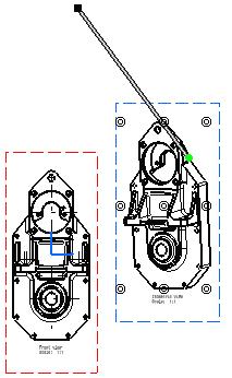
196

197 Positioning a View Independently of its Reference View At creation, views are by default positioned according to the parent (reference) view. This task will show you how to position a right projection view independently of its parent front view. This functionality was called Do not align view up until V5 R10. Open the GenDrafting_part.CATDrawing document. 1. Right-click the frame of the view that you want to position independently of its reference view. A contextual menu is displayed. 2. Select View Positioning -> Position Independently of Reference View. 3. Drag the view to the required location. 4. Click to position the view.
.")

198 The Position Independently of Reference View command can be performed on one particular view at a time (you cannot multi-select views in this case). If you want to reposition independently-positioned views according to their reference view, repeat the scenario described above, this time selecting the Position According to Reference View command from the displayed contextual menu.
 view of a resulting view. You can locate the resulting (i.e. child) view of a reference view. Open the GenDrafting_view_navigation.CATDrawing document.")
199 Locating Reference/Resulting Views This task shows how to navigate easily between reference/resulting views in the case of section views, section cuts, auxiliary views or detail views: You can locate the reference (i.e. parent) view of a resulting view. You can locate the resulting (i.e. child) view of a reference view. Open the GenDrafting_view_navigation.CATDrawing document. Locating a Reference View 1. Right-click the detail view. 2. In the contextual menu, select Locate Reference View. The application window is reframed on the view where the detail view callout is defined.


200 Locating a Resulting View 1. Right-click the detail view callout. 2. In the contextual menu, select Locate Resulting View. The application window is reframed on the detail view.
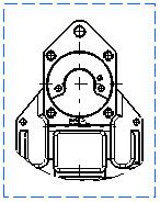
201
202 Isolating Generated Views This task will show you how isolate either a selection of generated views (one or more), or all views in the drawing. Isolating a view amounts to: suppressing associativity between an existing CATPart (or CATProduct or CATModel) and the corresponding generated view, transforming a generated view into an interactive view. Open the GenDrafting_part.CATDrawing document. Isolating a selection of views 1. Select the views you want to isolate (for example, the Top view, Bottom view, Left view and Right view), and right-click them. 2. From the contextual menu, select Selected objects -> Isolate. In this particular case, we selected several views but if you select only one view, the left view for example, then you need to select Left view object -> Isolate from the contextual menu.
. 2.")
203 The selected views are now isolated. If you perform one or more modifications on the CATPart, you will not be able to update the isolated views. Isolating all views in the drawing 1. From the specification tree, right-click the drawing object (GenDrafting_part in this case). 2. From the contextual menu, select Drawing object -> Isolate.

204 All views in the drawing are now isolated. If you perform one or more modifications on the CATPart, you will not be able to update the drawing. A view that has been isolated cannot be de-isolated. Center lines in isolated views are no longer associated to geometry, but just to a point. Axis lines in isolated views are no longer associated to geometry, but just to 2 points. Dimensions in isolated views are no longer associated to geometry.
205 Restoring Deleted Generated Elements In this task, you will learn how to restore generated elements that have been deleted from a view. Open the GenDrafting_Restore_Deleted.CATDrawing document. The view in this drawing was generated from a 3D part, GenDrafting_Restore_Deleted.CATPart. You do not need to open the part. 1. In the Drawing window, select the circle shown on the view and press the Del key. The circle is now deleted from the view. For the purpose of this exercise, you will now immediately restore the circle you deleted, but you could perform other operations before doing this (like save and close the drawing, or add annotations, for example). 2. Select the view and right-click the view frame. 3. In the contextual menu, choose Object Front View -> Restore Deleted. Remember that this is applicable only in exact views. If the view you are working in is not an exact one, the elements you deleted will be displayed again when updating the view. 4. You now have two possibilities: If you did not modify the part between the moment you deleted the circle and now (which is the case in this exercise): in the Power Input Field on the status bar, type the following command: c:force update. This updates the drawing in accordance with the 3D part, and restores the deleted item on the view. If you modified the part between the moment you deleted the circle and now: click the Update icon. This updates the drawing with the latest changes on the part, and restores the deleted item on the view.

206 Locking a View This task will show you how to lock views. This may be useful if you need to modify a part without modifying the generated views. For example, when you need to modify a constraint in the 3D but not the generated views. Locking a view means you are not allowed to: create views from a locked view create either annotations or dimensions on this locked view update, delete or cut the locked view. The move command is still available when views are locked. Open the GenDrafting_front_view.CATDrawing document. 1. Right-click the view to be modified (either the view frame or the view itself). 2. Select the Properties option from the contextual menu.

207 The Properties dialog box appears: 3. Select the View tab and select the Lock View check box. The other fields appear in gray indicating that you can no longer edit them. The views are locked as soon as you check the Lock View view button. The options OK, Apply and Cancel buttons (in the Properties dialog box) have no impact on the status of the view that is being locked. 4. The view is automatically locked. This is indicated in the specification tree:
208 Scaling a View This task will show you how to modify the scale of a view. Open the GenDrafting_detailview_scale.CATDrawing document. 1. Right-click the frame of the view to be modified. In this case, right-click the detail view. 2. Select the Properties option from the displayed contextual menu. 3. Enter the new Scale value in the Properties dialog box. For example, 3.
209 4. Click OK. The detail view is updated. Note that only the generative elements (axes included) are scaled, neither the view name nor the dimension.


210 Renaming a View This task will show you how to rename an existing view. Open the GenDrafting_Rename_View.CATDrawing document. 1. Right-click the frame of the view to be modified. 2. Select the Properties option from the displayed contextual menu. 3. Enter the new View Name in the Properties dialog box. For example, B as identifier (Ident). 4. Click OK.
211 You can also access the Properties dialog box selecting the Edit->Properties commands. Note that the callout in the mother view also is now assigned a new identifier (B-B).
212 Modifying a View Projection Plane This task will show you how to modify the projection plane of generated views. Open the GenDrafting_part.CATPart document. Tile your windows vertically to see both your part and the related drawing. 1. Create a front view of the part. 2. Create a right, left, bottom and top projection view. 3. Then create an auxiliary view of the top view. This type of auxiliary view created from the Projection view icon should not be mixed up with auxiliary views created thanks to the Auxiliary view icon. 4. Create a detail view on the front view. 5. In the Specification tree, right click and select Front view object/ Modify Projection plane. The front view and all the projection views are highlighted, showing the modification will impact all the views.


213 6. Select an edge of the part as your new reference plane. The front view with the new reference plane is previewed in the drawing. 7. Click on the drawing sheet to create the front view according to the reference plane you selected. The front view is updated and an update icon is displayed under each projection view.


214 The update is made in two steps: first the front view, then the views linked to the front view, that is, the projection views and the detail view. You will note that the detail view callout has become red because there is an inconsistency between the referring view and the detail view. 8. Right-click on each projection view and select Update selection in the contextual menu to update the view according to the new reference plane. or Right click on Drawing1 and select Update selection in the contextual menu. The right, left, bottom, top and auxiliary views are updated, as well as the detail view and the detail view callout goes black again since there is no more inconsistency.


215 The Modify Projection Plane option cannot be applied to the following views: top, bottom, right, left, auxiliary, detail, locked, isolated, interactive You cannot propagate the modification of a projection plane on a section or auxiliary view created from the Auxiliary view icon. You have to recreate them in order to take into account the new reference plane. You can apply modification projection plane on views that do not have a referring view such as: isometric views, views from 3D. 1. Create an isometric view of the part. 2. Modify the part position. 3. In the Specification tree, right click and select Isometric view object/ Modify Projection plane. 4. Click on the part. The isometric view with the new reference plane is previewed in the drawing.

. 8. In the drawing specification tree, select Front View.")
216 The isometric view is modified in the drawing. 5. Open the 3DViews.CATPart document. Tile the screen horizontally by selecting Window -> Tile Horizontally from the menu bar. 6. Create a new drawing in ISO standard. 7. Create a view from 3D on the FrontView.1 You can notice that one of the extracted annotations (datum B) bears a red cross mark, which indicates that the leader cannot be extracted linked to the geometry. This is because the 3D annotation leader is linked to 3D geometry which is not visible in the 2D view (i.e. hidden geometry). 8. In the drawing specification tree, select Front View.1 object/ Modify Projection plane. A message asking you if you want to synchronize the view projection plane is displayed.

217 9. Click on OK. Dress-up elements and callouts' behavior remain the same even when performing a Modify Projection plane. For more information on dress-up elements, refer to the Dress-Up Elements section and the Modifying a Callout Geometry section.
218 Generating a Bill of Material This task will show you how to insert Bill of Material information into the active view. The Bill of Material corresponds to information on the product element which the views were generated from. The Bill of Material, or parts list, consists of an itemized list of the parts of a structure shown on a drawing or on an assembly. The Bill of Material can also include a recapitulation of the total number of parts used in a product. Choose a task: generating a bill of material, modifying a bill of material: modifying the contents, modifying the contents visualization, updating a Bill of Material after part modification. Generating a Bill of Material Open the Product_Balloon.CATDrawing document. Open the Product_Balloon.CATProduct document. If the active view has no link with the product, a message will state whether the insertion is all right. If the active view has a link with a product, the Bill of Material can be inserted. Whether the active view has a link with a product or not, you can go into an open product and click on this product before clicking on the CATDrawing in which you want to insert the Bill of Material. Note that you can perform this as often as you need. You are in the background view You first selected Edit -> Background View from the toolbar. 1. Click the Insert Bill of Material icon from the Drawing toolbar. 2. Click the Product from the specification tree in the CATProduct document. 3. Position the Bill of Material by clicking the point where you want to insert it. OR You are in the working views You first selected Edit -> Working Views from the toolbar. 1. Select Insert -> Generation -> Bill of Material. 2. Position the Bill of Material by clicking the point where you want to insert it. In our example, click at the bottom right of the isometric view.
219 Whether you are in the background view or in the working views: Before positioning the Bill of Material, you can pre-define the anchor point position: this will determine the position of the Bill of Material in relation to the anchor point. For this, use the Text Properties toolbar and select either one of the top or one of the bottom anchor points. When positioning the Bill of Material, you can select a line, in a title block for example. In this case, the Bill of Material will be inserted according to the position and orientation of this element, and without including a recapitulation table. Note that, if no Product is or several Products are opened, you will first select the Product source. The Bill of Material automatically appears:

220 Modifying a Bill of Material Modifying the contents To modify the contents of the Bill of Material and display given properties, go to the Product Structure workbench, and select Analyze->Bill of Material ->Listing Report from the menu bar. Modifying the contents visualization To modify the way you visualize the contents, modify the file called CATAsmBOM.CATRsc. It allows you to modify the columns size:
221 Bill Of Material cells are associated to the Product Structure Attributes. Updating a Bill of Material after Part Modification
. 2. Update the drawing.")
222 Open the Product_Balloon.CATDrawing document. Open the Product_Balloon.CATProduct document. Add a bill of material. You obtain the following Bill of Material: 1. Replace the Part Number "pm6-7b-1e shunt to body washer" by "New Name" (for this edit Part Properties in the Part contextual menu, and change the Part Number in Product tab). 2. Update the drawing. The Bill of Material has changed, "pm6-7b-1e shunt to body washer" is replaced by "New Name".
: 4.")

223 3. Add a new product and a new part in this product (see Part Design user's guide and Assembly Design User's Guide): 4. Update the drawing, the Bill of Material is updated: The New product and its part appear in the Bill Of Material. 5. Remove the Product you have added in step 3 and update the drawing one more time:
224 As Bill of Material-related information is retrieved from the 3D, if you update a Bill of Material after having modified it directly in the drawing (e.g. if you changed the column size, edited text, etc.), all manually-applied changes are lost.
225 Generating Balloons on a View This task will show you how to generate in the active view balloons corresponding to references defined on the different parts of an assembly. Note that the assembly components have previously been numbered in the Product Structure workbench using the Generate Numbering command. For more information, refer to Generating Numbering in the Product Structure User's Guide. Open the Product_Balloon_Gen.CATProduct and Product_Balloon_Gen.CATDrawing documents. 1. Double-click the view in which you want to generate the balloons. In this particular case, doubleclick the front view. This view is now active. 2. Select the Generate Balloons icon on the Dimension Generation toolbar. The balloons that were previously created on the CATProduct are automatically generated onto the active view. 3. If needed, multi-select these balloons and modify the font size from the Text Properties toolbar. You can also select and drag a balloon to change its position.
226 Balloons generated Balloons after the font size and position were modified: 4. If needed, insert a bill of material into the active view (Insert -> Generation -> Bill of Material from the menu bar).
227

228 The part numbers appear in the bill of material on the condition you specified it previously (Product Structure workbench: Analyze -> Bill of Material -> Listing Report from the menu bar).
229 Showing Geometry in Views This task will show you how to visualize geometrical elements in all viewpoints as well as in a 3D viewer corresponding to the views analyzed. Note that you can analyze both text/dimension and edge type elements on all the views of a CATDrawing document. These views can be views generated from an assembly, a part or a.model. These views can also be interactive views. Open the GenDrafting_part.CATDrawing document. 1. Go to Tools -> Analyze -> Show Geometry in All Viewpoints menu bar command. Provided there is at least one link between the CATDrawing document and a CATPart (or assembly, part or.model), a window appears with the 3D model corresponding to the CATDrawing views. 2. Move the cursor over the geometrical elements on one view. All the views are analyzed. The blue color corresponds to the immediate edge. The red color corresponds to the adjacent faces.


230 If the Animate option is on, the part automatically appears with the optimal position (visually speaking).
231 Modifying a Callout Graphism This task will show you how to modify the graphical attributes of one (or more) callout used when generating auxiliary, section or detail views. Callouts represent an operation that has been performed on a generative view (such as a section cut for example) and consequently do not behave as geometry. As a result, you cannot isolate callouts, nor can you apply transformation or symmetry operations to callouts. Open the GenDrafting_part_Callout.CATDrawing document. 1. Multi-select the callout to be modified. In this example, we select both a section view callout and a detail callout. 2. Right-click these callout and select the Properties option from the contextual menu. 3. Select the Callout tab.


232 The preview displays both selected callouts with attributes corresponding to the generated views.
233 The options you select in the Graphic Properties toolbar also influence the graphical attributes you apply to the selected callout (line color, line type, line weight, Copy Object Format icon, Pattern Chooser option). In this dialog box, you can set the following parameters: Auxiliary/Section Views: Switches for pre-defined types: continuous lines, mixed lines, elbows and extremities only or one arrow only. Line thickness Line type Extremity thickness Length Anchor point (head or tail) Detail Views: Thickness Type Arrows on Auxiliary/Section Views and Detail Views: Arrow length Head type Head length Head angle You can specify that the size of callout elements should not be dependent on the view scale. For this: After callout creation, check Size not dependent on view scale in the previous dialog box. or Before callout creation, in Tools -> Options -> Mechanical Design -> Drafting -> Layout tab, check the Size not dependent on view scale option. This option will apply to newly created callouts, i.e. selecting this option will not have any impact on existing callouts. Note that this option only applies to drawings created with versions prior to V5 R11 (i.e. versions up to V5 R10). 4. Modify the callout graphical attributes as shown above.
234 5. Click OK.
235 Modifying a Callout Geometry This task will show you how to modify the geometrical characteristics of a callout used when creating detail views, section views and section cuts. For modifying the detail and section callout, you will go through some kind of a sub-workbench and modify the existing callout geometry, reverse the callout direction or replace the callout. Callouts represent an operation that has been performed on a generative view (such as a section cut for example) and consequently do not behave as geometry. As a result, you cannot isolate callouts, nor can you apply transformation or symmetry operations to callouts. Open the GenDrafting_part_Callout.CATDrawing document. 1. Double-click the callout to be modified. The Edit/Replace toolbar appears. 2. Drag one of the element components to the desired location. In this particular case, drag one segment extremity of the callout. By default and in order to modify more easily and more precisely the callout, the segment extremities are
236 fixed. To make one segment no more constrained, rightclick this segment and select the Line.object -> Unfix option from the contextual menu. 3. Click the End Profile Edition icon from the Edit/Replace toolbar. The callout arrow is now properly positioned and the section view (B-B) is automatically updated. Open the GenDrafting_part_Callout.CATDrawing document Double-click the callout to be reversed. Click the Invert Profile Direction icon from the Edit/Replace toolbar that now appears.
237 The callout is automatically inverted. At any time, you can stop editing the callout. For this, click the End Profile Edition icon from the Edit/replace toolbar. You cannot reverse the callout of a detail. If after modifying a view containing a callout, the projection planes of the defining and the resulting views are inconsistent, the callout becomes red to show that there is an inconsistency in the drawing. To have further information about red callouts, refer to the More about red callouts section below. 3. Click the Replace Profile icon from the Edit/Replace toolbar now appears. 4. Start creating the new profile.
238 5. Double-click to end the new profile creation. The new profile automatically appears and the old one disappears. More about red callouts Modification of callouts If you modify an auxiliary or a section callout in a way that the plane of the resulting view is not parallel anymore compared to the previous plane view or if you invert the profile: all the callouts of the resulting view are displayed in red, you cannot edit them, the change is not propagated to detail view. Translation of section callouts If you translate a section callout, the plane of the resulting section view is modified. It remains parallel to its previous orientation, yet there is a an inconsistency between the section view and the detail view defined on the previous plane view. As a consequence: the detail callout becomes red, other callouts remain unchanged, all callouts can be edited. If you create a detail view on the section view and translate the section callout without any visible impact on the resulting section view, the detail callout becomes red anyway and is editable.
239 Resizing of callouts If you resize a section callout constrained by the supporting lines of the profile: any detail callout does not turn into red, it can be edited

240 Overloading Element Properties This task will show you how to overload the properties of elements in a view generated from a CATProduct. You can select the elements to overload in the 3D document, either selecting a node or multi-selecting the elements in the specification tree. A number of the properties that you can overload are originally defined as properties of the 3D product component, in the Product Structure workbench. For more information on specifying the properties that should be used for a 3D component when generating views, refer to Modifying Component Properties in the Product Structure User's Guide. Open the GEAR-REDUCER_GS.CATProduct document and the GEAR-REDUCER.CATDrawing document. 1. Right-click the section view A-A. 2. In the contextual menu, select Section view A-A object -> Overload properties. The Characteristics dialog box is displayed. Select the element (part instance) that you want to edit. This element is highlighted in the drawing and listed in the dialog box.


241 You can also select several elements, if you want to overload their properties in the same way. In the case of several elements generated from a single part instance, all these elements are highlighted when you select one. 3. Select the element you want to edit (as there is just one in our example, it is already pre-selected) in the dialog box and click the Edit button. The Editor dialog box is displayed. You can modify the following parameters: Cut in section views: specifies that the 3D element will be cut in the section view, section cut or breakout view. Use when projecting: specifies that the 3D element will be projected in the view. Uncheck this option if you don't want an element to be represented in the view (other 3D elements possibly hidden by this element in the view will then be visible in the view). Represented with hidden lines: specifies that 3D hidden lines will be represented. Shown: specifies that the dress-up (color, line type, etc.) associated to the 2D generated element will be shown. The view is not re-computed. Graphic Properties area: lets you modify graphic properties such as element color, line type and line thickness.

242 The Cut in section views, Use when projecting and Represented with hidden lines properties are originally defined as properties of the 3D product component. So it is actually the properties of the 3D component that you are overloading. In this case, the view is re-computed. If Graphic Properties only are modified, the view is not re-computed. 4. Uncheck Cut in section views. 5. Click OK to validate and exit the dialog box. 6. Back in the Characteristics dialog box, click Apply. A dialog box is displayed while the view is being recomputed. The selected element is not cut anymore. 7. In the product's specification tree, select the Slow speed node. Back to the Drawing, the elements have been added to the Characteristics dialog box. 8. Select the last three elements in the list and click on the Edit button

 Back to the Drawing, the elements have been added to the Characteristics dialog box. 13. Select the last two elements in the list and click on the Edit button 14.")
243 9. In the Editor dialog box select the red color in the Graphic properties combo box. 10. Click OK to validate and exit the dialog box. 11. Back in the Characteristics dialog box, click Apply. A dialog box is displayed while the view is being recomputed. 12. In the product's specification tree, press the Ctrl key and multi-select Motor adaptator and Roller bearing (Roller bearing.2) Back to the Drawing, the elements have been added to the Characteristics dialog box. 13. Select the last two elements in the list and click on the Edit button 14. In the Editor dialog box uncheck Shown. 15. Click OK to validate and exit the dialog box. 16. Back in the Characteristics dialog box, click OK again. A dialog box is displayed while the view is being re-
244 computed. In the Characteristics dialog box, the Reset button allows you to recover the values you had before changing information in the Editor dialog box. In versions prior to V5 R13, in the case of faces overlapping with un-cut elements, the pattern area used to go over the projected faces and edges. From R13 onwards, the pattern area is now limited to the face sectioned on the part, as shown below. Previous behavior New behavior You can also set the Drafting properties in the 3D document so that they are propagated in the 2D view. 17. In the 3D document, right-click on the Bearing (Part1.1) instance. 18. Select Properties in the contextual menu and click on the Drafting tab. The Drafting properties are displayed.
245 19. Check Represented with hidden lines. 20. In the CATDrawing, click on the Update icon. The element is represented with hidden lines in the view. There is two ways to activate the Drafting properties: go to Tools->Options and check Apply 3D specifications in the View tab or right-click the view and select Properties, then check 3D spec in the View tab.

246 Modifying a Pattern This task will show you how to modify the pattern of a view. Patterns are used for area fills or, as is the case in this scenario, when cutting through material in section views/cuts or breakout views, for example. Open the GenDrafting_exploded_isometric.CATDrawing document. 1. Right-click the pattern to be modified. For the purpose of our scenario, select the hatching pattern in the Section view. 2. Select Properties from the displayed contextual menu. The Properties dialog box displays the view current pattern. 3. In the Properties dialog box that appears, click the Pattern tab.

247 4. If you want to define your own pattern, choose a pattern type from the Type drop-down list: Hatching Dotting Coloring Image Or if you want to choose from the various patterns available, click the [...] button. This will display the pattern chooser, from which you can make your selection. For the purpose of this scenario, select Dotting from the Type drop-down list.
248 5. In the Pitch field, type 5 mm. 6. From the Color drop-down list, select black, for example. 7. Uncheck the Zigzag field, and then click OK. The pattern is modified. Each part is assigned a specific pattern. Therefore, each time you modify a pattern using the Properties dialog box, all the patterns of the views generated from this part will be modified. These modifications will be applied to all existing sheets.
249 About part material patterns Depending on the standard used by the drawing, you may be able to recover the pattern which is associated to a part material on a section view/cut or breakout view. For more information about associating a pattern to a material, please refer to the Real Time Rendering User's Guide. When editing the properties of a pattern associated with a part material, the software offers its own selection of patterns, and not the patterns defined in the standard. When editing the properties of a pattern associated with a part material, a specific button is available in the Properties dialog box: Reset using Part Material Pattern. When the original properties of the part material are modified, this button is activated to let you revert to the original part material pattern. For example, if you replace a pattern associated with a part material by a pattern from the standard, then the generated pattern is considered as overloaded, and will not be updated if you modify the properties of the part material. In this case, you can always revert to the original part material pattern using the Reset using Part Material Pattern button.

250 Duplicating Generative Geometry This task will show you how to duplicate a generative view sub-element in order to modify a generated view sub-part independently from the part linked to the drawing. Open the GenDrafting_part.CATDrawing document. 1. Double-click the view you want to modify to activate it. The view is automatically highlighted. 2. Select the elements you want to modify and right-click them. 3. Choose Duplicate Geometry in the contextual menu.
251 The selected geometry is duplicated on the view at the same position. It is highlighted after creation. Click on the drawing to de-select it. The resulting geometry is under the generative one. To workaround this problem, you can hide the corresponding generative geometry.

252 Modifying a view's links This task will show you how to modify the list of pointed elements for a view and resolve broken links. Open the GEAR-REDUCER_GS.CATProduct document. 1. Create a new drawing sheet and tile windows horizontally using the Window -> Tile Horizontally menu item. 2. Create a front view of the part. 3. Right click and select Front view object > Modify Links in the contextual menu. Link Modification dialog box is displayed. You can see the whole assembly is selected. 4. In the 3D product, press the Ctrl key and select the following parts:

253 Roller bearing 1 Roller bearing 2 Slow speed shaft High speed shaft Motor adaptator 5. Back in the drawing, the parts have been added in the Link Modification dialog box. 6. Click on Add all. 7. Check Preview to see what the 3D product looks like according to your selection.


254 8. Click on OK. You can see that an update icon is displayed in the specification tree of the drawing. 9. Click on Update. The selected parts are displayed in the front view.
255 10. Right click and select Front view object > Modify Links. Link Modification dialog box is displayed with links related to the parts. 11. Select Motor adaptator and click on Remove. 12. Click on Preview to visualize your 3D product. 13. Press the Ctrl key, then click on High speed shaft and Roller bearing Click on Remove. The preview is updated.


256 15. Click on OK, then on Update. The front view is updated. If you remove all the pointed elements, you are back to the step when you first created the front view of your product or your part.

257 You can start selecting links again. 16. In the 3D product, press the Ctrl key and select the following parts: Roller bearing 1 Roller bearing 2 High speed shaft 17. Back in the drawing, the parts have been added in the Link Modification dialog box.

258 18. Click on OK, then on Update. 19. In the 3D product, delete Roller bearing 1. Broken links are displayed in the drawing specification tree. 20. Right click and select Front view object > Modify Links. A warning is displayed advising you to remove broken links. 21. Click on OK. The Link Modification dialog box is displayed with the broken link highlighted so taht you can remove it. 22. Click on Remove. 23. Click on OK, then on Update: the drawing is updated accordingly.
 if it is an assembly view, and bodies if it is a part view.")
259 As long as you do not remove broken links, you cannot modify the view at all. If all links are broken and removed, you are back in the Link Modification dialog box, the whole assembly being selected. All views must have the same 3D associated document. You can select products or subproducts or subassemblies (Voir assembly) if it is an assembly view, and bodies if it is a part view. If you want to modify links in your view when the related 3D document is not opened, you can only remove links. Undo and Redo are disabled. If you perform a Modify Links on an exploded view, all the views generated from the assembly will be modified. For more information on exploded mode, refer to the Creating an Exploded View section. If you perform a Modify Links on a scene, you can select the scene only. Would you need to select products in your assembly, you need to remove the scene's link in the Link Modification dialog box, then select products or parts' links only. Remember you cannot mix scene links and products or parts' links.


260 Applying a view's links to another view This task will show you how to apply a view's links to another view. Open the GEAR-REDUCER_GS.CATProduct document. Make sure no drawing is already open. 1. From the menu bar, select Start -> Mechanical Design. 2. Select the Drafting workbench. The New Drawing Creation is displayed with information on views that can possibly be created, as well as information on the drawing standards. 3. Select All views and click on OK. 4. Right click on the front view.
261 5. Select Front View object > Modify Links. The Link Modification dialog box is displayed. 6. In the 3D product, press Ctrl key, then select Worm gear and Motor adaptator parts. Back in the drawing, the parts are both displayed in the Link Modification dialog box.

262 7. Click on Add all and then on OK to close the Link Modification dialog box. An update icon is displayed in the specification tree under the front view node. 8. Click on Update. The front view is updated accordingly.


263 9. Right-click on the front View and select Front View object > Apply Links To. 10. Select the Bottom view. An update icon is displayed in the specification tree under the bottom view node. 11. Click on Update: the view is updated accordingly.

264 Only one view can be selected. If you try to apply the same links to the view = warning. The view must have the same 3D associated document.
265 Generative View Styles The Generative Drafting workbench lets you use generative view styles, which are administrator-defined and specify the appearance and behavior of a generated view. For more information on the administration of generative view styles, refer to the Administration Tasks chapter. Create views using generative view styles: Create views using generative view styles. Switch a view to another generative view style: Switch a view which uses a given generative view style to another style. Apply the generative style of a view to another view: Apply the generative view style used to create a given view to another view. Apply a generative view style to a view: Apply a generative view style to a view which was created without one.
266 Creating a View using Generative View Styles This task will show you how to create a view using generative view styles. Generative view styles are defined by an administrator and specify the appearance and behavior of a generated view. For the purpose of this scenario, you will create a front view using generative view styles, but you can use generative view styles to create any type of view. Open the GenDrafting_part.CATPart document. Define a new drawing sheet. 1. Go to Tools -> Options -> Mechanical Design -> Drafting -> Administration tab, and uncheck the Prevent generative view style creation option. This activates the generative view style functionalities. 2. Click the Front View icon from the Views toolbar. The Generative View Style toolbar is automatically displayed. 3. Select one of the generative view styles available from the list. For example, select DefaultGenerativeStyle. The parameters defined in this file will be used when creating the view.

267 The generative view styles available in the list refer to the file delivered with the application, as well as the generative view style files embedded in the drawing, but in case those files have the same name, only the embedded file is taken into account. The Generative View Style toolbar is displayed when creating most view types. However, when creating advanced front views, this toolbar is not displayed. Instead, the View Parameters dialog box (which is displayed when creating advanced front views) features an additional list, which enables you to select a generative view style. 4. In the 3D window, select a plane of the 3D part or a plane surface, to define the reference plane. 5. Click inside the sheet to generate the view.

268 The view is created using the selected generative view style. In our example, hidden edges are projected in orange. Note that you may obtain a different result. This result depends on the parameters defined in the generative view style you selected. Using the standards editor, you can check the parameters defined in the generative view style you selected. To do this, go to Tools -> Standards. In the standards editor, choose the generativeparameters category, and then open the DefaultGenerativeStyle.xml file from the drop-down list. Then, for example, go to DefaultGenerativeStyle -> Drafting -> ViewDressup - > GeneratedGeometry -> HiddenEdges, and select the Color parameter. You will see the what color is specified in your generative view style for the projection of hidden edges.

269 Switching a View to Another Generative View Style In this task, you will learn how to switch a view which uses a given generative view style to another style. Generative view styles are defined by an administrator and specify the appearance and behavior of a generated view. Open the GenDrafting_GVS.CATDrawing document. This view was created using a specific generative view style which specifies that hidden edges should be displayed in orange, using a specific linetype and thickness. 1. Go to Tools -> Options -> Mechanical Design -> Drafting -> Administration tab, and uncheck the Prevent generative view style creation option. This activates the generative view style functionalities.
270 2. Right-click the front view to display the contextual menu. 3. Select Front view object -> Generative View Style -> Change View Style. The Change Style dialog box appears, displaying the list of generative views styles available. The generative view styles available in the list depend on what your administrator specified. 4. Select a style, DefaultGenerativeStyle for example, and click OK. 5. Update the view by clicking the Update icon, for example.
271 The view is updated and the parameters defined in the selected style are applied to the view. In our example, hidden edges are projected in black, with a different linetype and thickness than previously. Note that you may obtain a different result. This result depends on the parameters defined in the generative view style you selected.

272 Applying the Generative Style of a View to Another View In this task, you will learn how to apply the generative view style used to create a given view to another view. Generative view styles are defined by an administrator and specify the appearance and behavior of a generated view. Open the GenDrafting_GVS02.CATDrawing document. The front view was created using a specific generative view style (which specifies that hidden edges should be displayed in orange, using a specific linetype and thickness), while the isometric view was created without a generative view style. 1. Go to Tools -> Options -> Mechanical Design -> Drafting -> Administration tab, and uncheck the Prevent generative view style creation option. This activates the generative view style functionalities.

273 2. Right-click the front view to display the contextual menu. 3. Select Front view object -> Generative View Style -> Apply View Style to. 4. Click on the isometric view to indicate that you want to apply to it the generative style of the front view. 5. Update the view by clicking the Update icon, for example.

274 The isometric view is updated and the generative view style of the front view is applied to it.

275 Applying a Generative View Style to a View In this task, you will learn how to apply a generative view style to a view which was created without one. Generative view styles are defined by an administrator and specify the appearance and behavior of a generated view. Open the GenDrafting_front_view.CATDrawing document. This view was created without a generative view style. 1. Go to Tools -> Options -> Mechanical Design -> Drafting -> Administration tab, and uncheck the Prevent generative view style creation option. This activates the generative view style functionalities. 2. Right-click the front view to display the contextual menu. 3. Select Front view object -> Generative View Style -> Change View Style. The Change Style dialog box appears, displaying the list of generative views styles available.

276 The generative view styles available in the list depend on what your administrator specified. 4. Select a style, DefaultGenerativeStyle for example, and click OK. 5. Update the view by clicking the Update icon, for example. The view is updated. However, the selected style is not visible in the view yet. For the moment, the geometry is displayed in a specific color, because the original parameters of the view "overload" the generative view style parameters. (This means that the parameters of the selected generative view style have taken on the value of the parameters that were defined in the view before you applied the style to it.) You now need to reset the parameters of the generative view style to their original values in order for the new style to be visible in the view. 6. Right-click the front view to display the contextual menu once again. 7. Select Properties. The Properties dialog box is displayed. 8. On the View tab, in the Dress-up area, an asterisk * appears in front of the parameters which are considered as being overloaded.


277 The list in the Generative view style area shows the generative view style which is applied to the view. 9. Click the Reset to style values button, and then click OK to validate and exit the Properties dialog box. The view is updated once again and the parameters defined in the selected generative view style are reset to their original values and are applied to the view. In our example, hidden edges are projected in orange, with a different linetype and thickness than previously. Note that you may obtain a different result. This result depends on the parameters defined in the generative view style you selected.
278 Dimension Generation The Generative Drafting workbench provides a simple method for generating dimensions. Generated dimensions are associative to the elements created from a part or an assembly. Before you begin: All you need to know before you start generating dimensions. Generate dimensions in one shot: Generate dimensions in one shot from the constraints of a 3D part (distance, length, angle, radius and diameter constraints). Filter dimensions to be generated: Set filters before dimension generation using the Dimension Generation Filters dialog box. Generate dimensions semi-automatically: Generate dimensions step by step from the constraints of a 3D part (distance, length, angle, radius and diameter constraints). Analyze generated dimensions: Perform an analysis of generated dimensions via the Generated Dimensions Analysis dialog box. Position dimensions: Position dimensions (either generated dimensions or interactive dimensions) in a better way and on the active view exclusively. Analyze interfering dimensions: Analyze dimensions that were generated and possibly re-positioned (Positioning icon) on the active view. Driving 3D constraints via generated dimensions: Drive a 3D constraint via a 2D dimension that was generated from it.
279 Before you begin This section provides the relevant information you need when performing dimensions generation, whichever command you activate to do so. In other words, the rules described in the following section are valid either when performing a Dimension Generation in One Shot or a Semi-Automatic Dimension Generation. First of all, make sure you customize the dimension generation settings settings via Tools -> Options -> Mechanical Design -> Drafting -> Generation tab. How are Generated Dimensions Positioned? Generated dimensions are positioned according to the views that are most representative. In other words, a dimension will appear on a view so that this dimension needs not be also created on another view. Generated dimensions will be positioned according to the following criteria: 1. on the view on which the dimension may be generated. 2. on the view on which the dimension is better visualized. For example, a view on which elements are visualized in non-hidden lines instead of hidden lines. 3. on the view with a bigger scale. 4. on views including more dimensions. The dimensions are generated on the views on the condition the appropriate settings were previously activated in Tools -> Options -> Mechanical Design -> Drafting -> Generation tab. What About the Dimensions that may be Generated from Constrained 3D Elements? To make sure the dimensions you need to handle in your session are those expected, here is a list presenting the constrained 3D elements and the resulting associated dimensions after generation. Note that for views that are generated from surfaces, only sketched constraints are generated. Constrained 3D Elements Sketcher 3D part Features: User-defined Generated Dimension Types All dimensions: angle, distance, radius, diameter Angle, distance The dimensions below: All published dimensions of elements included in the user-defined feature Pad Distance Pocket Distance Shaft/Groove Angle Hole: Constraints and associated dimensions:
280 - Simple - Tapered - Counterbored - Countersunk - Counterdrilled - Threaded Fillet constraint variable Radius/Radii Shell Distance Thickness Distance Stiffener Distance Assembly constraints All assembly dimensions
281 About threaded hole dimensions A fractional dimension is generated for threads/taps defined in a 3D part which use standards with fraction as a symbolic representation (e.g. G1/8). This dimension is a fake dimension. It will be displayed using the color configured for fake dimensions in Tools -> Options -> Mechanical Design -> Drafting -> Dimension tab, Analysis Display Mode category. Note that although it is a fake dimension, it always updates properly. When using ISO standard values, the dimension displayed is a real one (displayed as Mxx) and is based on a key. When using personal standards including a thread description field, a fake dimension is displayed. If the description field does not contain any value, a real dimension is used, based on the key and the value of the nominal diameter. For more information about Threaded Holes and standards, refer to the Creating Threaded Holes section in the Part Design User's Guide.
282 Generating Dimensions in One Shot Before you begin, make sure you customized the following settings: Dimension generation: Go to Tools->Options->Mechanical Design->Drafting, and click on the Generation tab. Check the Analysis after generation option. This task will show you how to generate dimensions in one shot from the constraints of a 3D part. Only the following constraints can be generated: distance, length, angle, radius and diameter. Constraints may be of three kinds: created manually (i) via the sketcher or (ii) via the 3D part, or else (iii) automatically created via internal parameters. Open the GenDrafting_front_view.CATDrawing document. Open the GenDrafting_part.CATPart document. 1. Click the Generate Dimensions icon from the Generation toolbar (Dimension Generation subtoolbar). The dimensions are automatically generated on the front view, which in this particular case, is the only view in the drawing. In the case of drawings with several views, by default, dimensions are generated on all the views. To generate dimensions on specific views, simply select these views prior to generating dimensions. The selected views will be automatically highlighted, and dimensions will be generated on the selected views only. Drawing view with generated dimensions and one selected dimension: 3D part with displayed dimension corresponding to the dimension selected on the drawing view:
 is automatically displayed.")
283 The Generated Dimensions Analysis dialog box showing the dimensions and constraints generated for each part (in this case, there is only one) is automatically displayed.
284 2. Click OK to close the dialog box. The generated dimensions are positioned according to the most representative views. In other words, a dimension will appear on a view so that this dimension needs not be also created on another view.
285 Filtering Dimension Generation This task will show you how to set filters before dimension generation using the Dimension Generation Filters dialog box. Open the GEAR-REDUCER.CATProduct and the GEAR-REDUCER.CATDrawing documents. Tile your windows horizontally to view both your drawing and the related part. To do this, select Window -> Tile Horizontally from the menu bar. Go to Tools->Options->Mechanical Design->Drafting, and click on the Generation tab. Check the Filters before generation option. This automatically launches the dimension generation filters before generating dimensions. 1. By default, dimensions will be generated on all views. If you want to generate dimensions on a specific view, select this view. 2. Click the Generate Dimensions icon from the Generation toolbar (Dimension Generation sub-toolbar). The Dimension Generation Filters dialog box is automatically displayed.
286 The Dimension Generation Filters dialog box displays the parameters and filters that you can use for dimension generation, lists the elements for which dimensions will be generated, and specifies how many constraints there are for each listed element. Let's describe the dialog box more precisely: Type of constraint These options let you specify what type of constraints you want to generate dimensions from in your drawing. Sketcher constraints: generates dimensions from constraints created in the Sketcher workbench. 3D constraints: generates dimensions from 3D constraints (for instance an Offset between two planes). Assembly constraints: generates dimensions from assembly constraints. This option is active only in the case of products or assemblies. Measured constraints: generates dimensions from measured constraints. Options These options let you generate additional dimension types....associated with un-represented elements: generates dimensions from constraints associated with elements that are not represented on the drawing (i.e. which are not visible in the various views your drawing may contain). In this case, the generated dimensions will appear as not attached to any element in the drawing....with design tolerances: generates dimensions from constraints with design tolerances, and applies the
287 constraint tolerance to the corresponding generated dimension. Other Retrieve excluded constraints: retrieves all the constraints which you previously excluded (either using the Not Generated icon when performing a step by step generation, or by removing a generated dimension from the drawing), and re-generates the dimension. This icon is active only when there are dimensions to retrieve. Add all parts: adds all parts that belong to the selected product or assembly to the list. This button is active only in the case of products or assemblies. Remove: removes the selected element from the list. Dimensions will not be generated for this element. By default, only the product is displayed in the list of elements for which dimensions will be generated, and only the Assembly constraints and Measured options are active: if you left the dialog box as is, dimensions would only be generated from the product assembly constraints and measured constraints. 3. You will now add additional elements to generate dimensions for. You have two possibilities: If you want to generate dimensions for specific elements only: in the drawing, select each element for which you want to generate dimensions. The elements you select are added to the list. If you want to generate dimensions for all elements, click the Add all parts button to add to the list all the parts belonging to the product. For the purpose of this exercise, click the Add all parts button. All elements are added to the list. You can notice that the Sketcher constraints and 3D constraints options are now active and selected.
288 When the same part is used several times within a given product (as is the case for Bearing (Part1.1) in this scenario), generations for this part are generated only once, for a single part instance (instead of being generated for all part instances). By default, dimensions are generated on the part instance which is the first in the product specification tree. If you want to generate dimensions on a specific part instance, you need to select this instance. 4. Unselect the 3D constraints option to specify that dimensions from 3D constraints should not be generated. You can notice that the list is updated with the proper number of constraints for each element.

289 5. Click OK. The dimensions are generated on the drawing.

290 Depending on whether the Analysis after generation option was selected in Tools->Options, the Generated Dimension Analysis dialog box may now appear. 5. Click OK to close the Generated Dimension Analysis dialog box.

291 Generating Dimensions Semi-Automatically Before you begin, make sure you customized the following settings: Dimension generation: Go to Tools->Options->Mechanical Design->Drafting, and click on the Generation tab. Check the Analysis after generation option. This task will show you how to generate dimensions step by step from the constraints of a 3D part. Only the following constraints can be generated: distance, length, angle, radius and diameter. Constraints may be of three kinds: created manually (i) via the sketcher or (ii) via the 3D part, or (iii) automatically created via internal parameters. Open the GenDrafting_part.CATDrawing. In this sample, constraints were manually created. You will then go to Generative Drafting workbench and create views from this part. 1. Select the views on which you want to generate dimensions. For example, the front view. 2. Click the Generate Dimensions Step by Step icon from the Generation toolbar (Dimension Generation sub-toolbar). The Step-by-step generation dialog box displays and will remain displayed until the end of the dimension generation.
292 3. Check the Visualization in 3D button to see the constraints corresponding to the dimensions to be created on the views. 4. Check the Timeout option. The default timeout is set to two seconds (2s). Enter the timeout value you need for example, three seconds (3s). 5. Click the Next Dimension Generation switch button to start the dimension generation. Dimensions appear one after the other on the views. Now, you might need to pause the generation for modifying the dimension position for example. 6. Click the Pause in Dimension Generation switch button. The generation is paused. 7. Select the dimension to be modified. 8. Drag the dimension to its new position.
293 Note that, at this step (pause), you can perform all kinds of modifications before the dimension generation. You want the dimension last generated before you clicked the Pause switch not to be generated on the view? Perform as follows: 1. Click the Not Generated option in the Step by Step Generation dialog box. The constraint is automatically excluded and the dimension will not generated. You want the currently generated dimension to be transferred (via Transfer icon)? Perform as follows: 1. Click the Transfer icon from the Step-by-Step Generation dialog box. 2. Click the Pause switch. 3. Select the frame of the view in which the current dimension, or the dimension last created, is to be pasted. You want to modify the graphical attributes of the current dimension? Perform as follows: You simply need to apply the desired attributes in the required Properties toolbar. 9. Click again the Next Dimension Generation switch button and continue the process.
294 The dimensions are automatically generated on all the views. The dimensions appear as shown, for example, on the front view documented in this particular case. The Generated Dimensions Analysis dialog box showing the dimensions and constraints generated for each part (in this case, there is only one) is automatically displayed. This dialog box is described in detail in Dimension Generation Analysis.

295 Note that you can stop at anytime the generation by clicking or, on the contrary, accelerate the process by clicking.
296 Analyzing Generated Dimensions This task will show you how to analyze generated dimensions via the Generated Dimension Analysis dialog box. Open the GenDrafting_part.CATPart and then the GenDrafting_front_view.CATDrawing documents. Tile your windows horizontally to view both your drawing and the related part. To do this, select Window -> Tile Horizontally from the menu bar. Go to Tools->Options->Mechanical Design->Drafting, and click on the Generation tab. Check the Analysis after generation option. This automatically launches the generated dimensions analysis after dimension generation. 1. Click the Generate Dimensions icon from the Generation toolbar (Dimension Generation subtoolbar).
297 The dimensions are generated on the view. You can select a dimension in the drawing to highlight the corresponding constraint in the 3D, and vice-versa. The Generated Dimension Analysis dialog box is automatically displayed.
.")
298 The Generated Dimension Analysis dialog box displays the number of constraints available in the 3D, as well as the number of dimensions generated on the drawing, for each part or product in the drawing (in this case, there is only one part). You can use the options in this dialog box to highlight the dimensions in the drafting sheet as well as the associated 3D constraints you can visualize in your Part or Product document. Let's describe the dialog box more precisely: Constraint Analysis in 3D These options let you highlight specific constraints on the 3D part. Generated constraints: highlights all the constraints which are associated with the dimensions generated on the drawing. Other constraints: highlights all the constraints for which dimensions have not been generated on the drawing. Excluded constraints: highlights all the constraints which have not been taken into account during the dimension generation (this can be because you previously excluded them using the Not Generated icon when performing a step by step generation, or because you removed a generated dimension from the drawing). Dimension Analysis in 2D


299 These options let you highlight specific dimensions on the drawing. New Generated Dimensions: highlights the dimensions which were generated during the latest dimension generation (this is useful if you generate dimensions several times). Generated Dimensions: highlights all the generated dimensions. Other Dimensions: highlights the dimensions created manually via the Interactive Drafting workbench. 2. Check the Generated constraints and Generated Dimensions options. The generated dimensions are highlighted on the drawing, and the constraints associated with the generated dimensions are highlighted on the 3D part. 2. Click OK to close the dialog box.
300 The Analysis after generation option automatically displays the Generated Dimension Analysis dialog box (after dimension generation), each time you generate dimensions either automatically (Generating Dimensions icon ) or semi-automatically (Generating Dimensions Step by Step icon ). By default, the Analysis after generation option in Tools->Options is checked, and the Generated Dimension Analysis dialog box is automatically displayed at the end of dimension generation. You can deactivate this default by unselecting the Analysis after generation option. You can also launch an analysis explicitly when needed. To do this, go to Tools->Dimension Generation->Analysis. The Generated Dimension Analysis dialog box will be displayed immediately.
301 Positioning Dimensions (View per View) This task will show you how to position distance and length dimensions (either generated dimensions or interactive dimensions) in a better way. These dimensions will be positioned on the active view exclusively. Open the GenDrafting_part_ positioningdim.catdrawing document. In addition, select the View -> Toolbar -> Positioning option from the menu bar in order to have the necessary toolbar (Positioning toolbar) displayed in the workbench. 1. Click the Dimension Positioning icon from the Positioning toolbar. OR 1. Select Tools -> Positioning -> Dimension Positioning... from the menu bar. The dimensions are automatically re-positioned.
302 If you want to have dimension interferences analyzed, use the Dimension Analysis icon (or select Tools->Analyze->Dimension Analysis from the menu bar). You will thus be able to visualize and manage interfering dimensions.

303 Analyzing Interfering Dimensions This task will show you how to analyze dimensions that were generated and possibly re-positioned (Positioning icon) on the active view. Open the GenDrafting_part_ positioningdim02.catdrawing document. In addition, select the View -> Toolbar -> Analyze option from the menu bar. 1. Click the Dimension Analysis icon from the Analyze toolbar. OR 1. Select Tools -> Analyze -> Dimensions Analysis from the menu bar. The Analyze dialog box appears with the following options: List with all the annotations badly placed/optimized list with the annotations badly placed You can choose to have either a whole or a filtered list with the interfering elements
304 Total number of elements in the current list As you choose the above list type, the total number of interfering elements is automatically updated Number of the pointed element You are provided a number for the element currently pointed as an interfering element Scanner (Start, Before, Update, Next, End) You can navigate among the list of interfering elements The interfering dimensions are automatically displayed in the red orange color. Small circles allow visualizing the interference location.
305 2. Select Optimized list with the annotations badly placed option. 3. Click the Next switch. 4. Start modifying the dimension positions one after the other. Note that you may either re-position one dimension or either delete or copy this dimension, if needed. View with interfering dimension (Number 3): View once the interfering dimension has been deleted: The Analyze tool is designed to analyze basic interfering elements, thus it does not take into account advanced dimension manipulation such as leaders lines that might have been interrupted previously.
306 Driving 3D Constraints via Generated Dimensions In this task, you will learn how to drive 3D constraints via generated dimensions. Go to Tools -> Options -> Mechanical Design -> Drafting. On the Dimension tab, select Activate analysis display mode. Then, click the Types and colors button to define the characteristics that will be assigned to constrained geometry. The Types and colors of dimensions dialog box lets you select the colors you want to assign to driving dimensions. Select the colors shown below, for example. On the Administration tab, make sure that the Prevent dimensions from driving 3D constraints option is not selected. Open the Pinmounting.CATPart document.
.")
307 Open the GenDrafting_drive_3dconstraints.CATDrawing document. 1. On the front view, double-click the dimension which defines the top radius (Dimension.5 object). The Constraint Definition dialog box appears.
. The Parameter Definition dialog box appears.")
308 2. Type 30 in the radius field to change the radius definition, and click OK. The dimension is edited. 3. On the top view, double-click the dimension which defines the rounded corner radius (Dimension.1 object). The Parameter Definition dialog box appears.


309 4. Type 30 in the value field, and click OK. The dimension is edited. 5. In the CATPart window, click the Update button to update the part. The part is updated and reflects your modifications: 6. In the CATDrawing window, click the Update button to update the drawing. The drawing is updated with the latest modifications in the part:
310
311 Dimension Manipulation The Generative Drafting workbench enables you to create and modify dimensions. Note that dimension commands are actually provided with the Interactive Drafting workbench. Therefore, this section of the documentation actually points to the Interactive Drafting User's Guide. As such, the information detailed in this section is presented in an Interactive Drafting context. If you want to manipulate dimensions in a Generative Drafting context, you can open the GenDrafting_part.CATDrawing document. These dimensions will be associative to the elements created from a part or an assembly. When created, these elements are associated with a view. Note that for views that are generated from surfaces, only sketched constraints are generated. Before you begin: You should be familiar with basic concepts. Create dimensions: Create dimensions by clicking elements. Create half-dimensions: Create half dimensions on distance, angle, diameter, cylinders, diameter edges and diameter tangents but not on cumulate dimensions. Create cumulated dimensions: Create cumulated dimensions on a view using selection. Create stacked dimensions: Create stacked dimensions using selection. Create explicit dimensions: Create dimensions using explicit selection both of the desired icon and of the required geometrical elements. Create/modify angle dimensions: Create an angle dimension and perform the following kinds of modifications: new angle sector or turn an angle sector into a supplementary sector. Create chamfer dimensions: Create a chamfer dimension using selection. Create associative thread dimensions: Create associative thread dimensions. Create/modify coordinate dimensions: Automatically create coordinate dimensions on elements.
312 Create a holes dimensions table: Create a table containing holes dimensions (diameter and center coordinates). Create points coordinates table: Create a table containing 2D and 3D points coordinates. Create/modify radius curvature dimensions: Create and modify a radius curvature dimension. This lets you know the curvature radius at a given point on a curve (spline, ellipse, etc.). Create overall curve dimensions: You can create dimensions on the overall size of any kind of curve, whether it is canonical or not (e.g.: line, circle, ellipse, spline, etc.). You can also create dimensions on the overall size between 2 curves, or between a curve and a line, for example. Create curvilinear length dimensions: You can create dimensions for the curvilinear length of a curve, i.e. measure the overall length of a curve. Create dimensions along a reference direction: You can create dimensions along a direction of measure. In other words, you can measure the projection of a segment/distance onto a direction. Create dimensions between intersection points: You can create dimensions between an intersection point and an element or between two intersection points. Create dimensions between an element and a view axis: Create dimensions between an element and a view axis (one of the two axes or the origin). Modify the dimension type: Modify the dimension type as you create a dimension. On other words, you modify the dimension attributes. Re-route dimensions: Re-route dimensions, i.e. recalculate dimensions taking into account new geometry elements. Interrupt one or more extension lines: Interrupt manually one or more extension lines of one or more dimensions, either using the contextual menu or the Insert menu bar option. Modify the dimension line location: Use the mouse to modify dimension line location either before or after creating dimensions. Modify the dimension value text position: Use the cursor to modify dimension value text position. Specify the dimension value position: Automatically or explicitly position the dimension value inside or outside the area between extremity symbols. Add text before/after the dimension value: Insert text before or after the dimension value. Modify the dimension overrun/blanking: Use the Blanking Edition dialog box to modify dimension overrun or blanking. Line up dimensions (free space): Line up dimensions relatively to a point in the free space. Line up dimensions (reference): Line up dimensions according to a given reference. Create a datum feature: Use the Datum Feature Creation dialog box to create a datum feature. Modify a datum feature: Modify a datum feature by editing it. Create a geometrical tolerance: Use the Geometric Dimensioning And Tolerancing Parameters dialog box to create geometrical tolerances. Modify a geometrical tolerance: Use the Geometric Dimensioning And Tolerancing Parameters dialog box to modify geometrical tolerances. Copy a geometrical tolerance: Copy an existing geometrical tolerance and then edit the content for creating a new one. Create driving dimensions: Create dimensions that will drive associated constrained geometry.
313 Creating Associative Thread Dimensions This task will show you how to create associative thread dimensions. Open the thread.catdrawing document. 1. Click the Thread Dimension icon from the Dimensioning toolbar (Dimensions sub-toolbar). 2. Select the thread to be dimensioned in the front view. The diameter dimension appears. 3. Click the Thread Dimension icon. 4. Select the only one of the thread elements in the section view, two dimensions appear: the thread diameter the thread depth
314 In the top views you can modify threads dimensions orientation.
315 Technological Feature Dimensions The Interactive Drafting workbench lets you create dimensions for technological features such as electrical harness, or between technological features such as structural plates. Before you Begin: You should be familiar with basic concepts. Creating Intra-Technological Feature Dimensions: Create dimensions for technological features such as electrical harness. Creating Inter-Technological Feature Dimensions: Create dimensions between technological features such as structural plates.
316 Before you Begin There are a few things you should know before you begin creating technological feature dimensions. Technological feature dimensions let you create dimensions for technological features such as electrical harness or structural stiffeners, or between technological features such as structural stiffeners. Technological feature dimensioning relies on the fact that technological features can specify the way they should be dimensioned, which allows you to create only realistic and customized dimensions, based on the know-how of a given discipline. Depending on the type of feature that you will be dimensioning, you need specific product licenses to create technological feature dimensions. For more information on the availability of technological feature dimensioning for a given workbench, refer to the related documentation. Action/object and Object/action Mode Technological feature dimensioning is available in action/object mode (i.e. selecting the command first and then the feature to dimension) and in object/action mode (i.e. selecting or multi-selecting the feature(s) to dimension and then selecting the command). Technological Feature Dimensions icons Several Technological Feature Dimensions icons are available from the Technological Feature Dimensions sub-toolbar. Technological Feature Dimensions creates any type of technological feature dimension (intra or inter) specified by the feature, depending on the option selected in the Tools palette. Multiple Intra Technological Feature Dimensions icon create either the intratechnological feature dimension type specified by the feature when only one is specified, or the preferential intra-technological feature dimension type specified by the feature when several are specified. Chained Technological Feature Dimensions icon create either the inter-technological feature dimension type specified by the feature when only one is specified, or the preferential inter-technological feature dimension type specified by the feature when several are specified. Length Technological Feature Dimensions, Angle Technological Feature Dimensions, Radius Technological Feature Dimensions and Diameter Technological Feature Dimensions create a specific dimension type when the feature specifies several dimension types. Using one of these options is particularly useful when you want to create a dimension type other than the preferential type specified by the feature. Contextual menu

317 At any time during the dimension creation, you can right-click a technological feature to display a contextual menu. This contextual menu is particularly useful when several dimension types can be created for a given feature. This depends on what is specified by the feature. Optional choices, available when several dimension types are available for the selected feature or features, let you specify a single dimension type that you want to create, out of all the types available. The All option creates all available dimensions for all selected features. The None option creates none of the available dimensions for all selected features. The Show Panel option lets you display the Technological Feature Dimensioning Selection dialog box. Technological Feature Dimensioning Selection dialog box The Technological Feature Dimensioning Selection dialog box lets you select precisely the types of dimensions that you want to create for a given feature. This dialog box is particularly useful when several dimension types are available for a given feature (especially when creating inter-feature dimensions). From the list area, you can select the types of dimension that you want to create for a given feature or de-select those that you want to delete. You can also use the Create drop-down list. The default option, (Selected), creates the dimension types selected from the list area above. The All option creates all available dimensions for all selected features. The None option deselects all available dimensions for all selected features. The Hide button lets you hide the Technological Feature Dimensioning Selection dialog box. When a feature is checked and grayed out as shown below, it means that not all dimensions available for this feature have been selected.

318 You can also show or hide the Technological Feature Dimensioning Selection dialog box using the Show Panel icon available in the Tools Palette. Limitations You cannot create coordinate, stacked and curvilinear dimensions for technological features.
319 Creating Intra-Technological Feature Dimensions This task will show you how to create dimensions for technological features such as electrical harness. You need an Electrical Harness Assembly license for the purpose of this scenario as we will be dimensioning Electrical Harness Assembly features. Intra-technological feature dimensioning is also available for other applications such as Structure Functional Design or Ship Structure Detail Design. For more information on the availability of technological feature dimensioning for a given workbench, refer to the related documentation. Refer to Before you Begin for general information about technological feature dimensions. Open the ElectricalAssembly.CATProduct document and make sure it is loaded in the Electrical Harness Assembly workbench (if necessary, select Start -> Equipment & Systems -> Electrical Harness Assembly to launch the workbench). Open the ElectricalAssembly.CATDrawing document. 1. Click the Multiple Intra Technological Feature Dimensions icon from the Dimensioning toolbar, Technological Feature Dimensions sub-toolbar. You can also click the Technological Feature Dimensions icon Multiple Intra Technological Feature Dimensions icon and then select the from the Tools Palette. 2. Select the feature that you want to dimension. Note that the name of a feature is displayed as a help as you move the cursor over it.
320 The dimension is created as specified by the feature. In this specific example, the bundle segment specifies that the dimension should provide its overall length. The dimension creation command remains active. 3. Repeat step 2 for each additional feature that you want to dimension. 4. End the dimension creation by clicking anywhere in the drawing (but not on a technological feature) or by lining-up the dimension. The intra-feature dimensions are created as specified by the feature. You can now handle the dimension(s) just like any other dimension.
321
322 Creating Inter-Technological Feature Dimensions This task will show you how to create dimensions between technological features such as structural stiffeners. You need a Structure Functional Design or a Ship Structure Detail Design license for the purpose of this scenario as we will be dimensioning Structure features. Inter-technological feature dimensioning may also be available for other applications. For more information on the availability of technological feature dimensioning for a given workbench, refer to the related documentation. Refer to Before you Begin for general information about technological feature dimensions. Open the MemberForDim.CATDrawing document. For your information, this document references the MemberForDim.CATProduct document. You do not need to open this product. 1. Click the Chained Technological Feature Dimensions icon from the Dimensioning toolbar, Technological Feature Dimensions sub-toolbar. You can also click the Technological Feature Dimensions icon and then select the Chained Technological Feature Dimensions icon from the Tools Palette. 2. Select Ref_FunStiffener_002 as the first feature for dimensioning. Note that the name of a feature is displayed as a help as you move the cursor over it. 3. Select Ref_FunStiffener_001 as the second feature.
323 A preview of the dimension is displayed. The dimension creation command remains active. 4. Right-click to display the contextual menu. 5. Select Angle between supports (true dimension). The next dimension will be created between the previously selected feature (i.e. the second feature you selected) and the next feature you select. 6. Select the third feature.
324 You can also right-click to view the various types of dimensions you can create between the features. For the purpose of this scenario, leave Distance between parallel supports (true dimension) selected. 7. Optionally move the dimension to position it as wanted. 8. When done, click in the drawing (but not on a technological feature) to create the dimension. The interfeature dimensions are created as specified by the feature. You can now handle the dimensions just like any other dimension. Note that the dimension arrow is automatically oriented according to the direction of material (in this case, the stiffener's molded side), which is the case when dimensioning structural features.
325
326 Annotations The Generative Drafting workbench lets you manipulate annotations. Note that annotation commands are actually provided with the Interactive Drafting workbench. Therefore, this section of the documentation actually points to the Interactive Drafting User's Guide. As such, the information detailed in this section is presented in an Interactive Drafting context. If you want to manipulate annotations in a Generative Drafting context, you can open the GenDrafting_part.CATDrawing document. In order to be consistent with the way commands have been grouped in toolbars and sub-toolbars, the following tasks are documented in the Manipulating Dimensions chapter: Datum Feature Creation and Modification Geometrical Tolerance Creation, Modification and Copy See Before you begin to learn about important concepts, including setting text properties. Before you begin: You should be familiar with basic concepts such as setting the properties of a text (font style, size, justification, etc.), using default values, and specifying the position and/ or orientation of a text. Create a free text: Create a text that either wraps or not, that is assigned an unlimited width text frame, even though this text may reach the frame boundary. Create an associated text: Create a text which you want to be and remain associated to an existing element. Make an existing annotation associative: At any time and once an annotation has been created, you can add a link between an annotation and another element. Create a text with a leader: Create a text with a leader either in the free space or associated with an element. Add a leader to an existing annotation: Add a leader to an annotation that was previously created. Handle annotation leaders: Add or remove breakpoints, extremity or interruptions. Move and position leader breakpoints. Add frames and sub-frames to existing text: Add a frame or a sub-frame to a text that was previously created. Replicate a text and attribute: Replicate text as well as the corresponding text attribute. Copy text graphical properties: Copy the text graphical properties of an annotation or element to other elements. Create a datum target: Create a datum target on a view. Modify a datum target: Modify a datum target by editing it in a dialog box.
327 Create a balloon: Create a balloon using a dialog box. Creating an associative balloon on a generated product view: Create associative balloons on views generated from a product. Modify a balloon: Modify a balloon using a dialog box. Create a roughness symbol: Create a roughness using a dialog box. Create a welding symbol: Create a welding symbol using a dialog box. Create a geometry weld: Create a geometry weld symbol. Modify annotation positioning: Assign new positioning to existing annotations. Create/modify a table: Create, edit and modify a table. Find/replace text: Locate and then, if needed, replace strings of characters. Perform an advanced search: Use the advanced search command. Query object links: Query object links in a drawing. Adding attribute links to text: Add one or more attribute links between text that was previously created.
328 Dress-Up Elements The Generative Drafting workbench enables you to create a number of view dress-up elements on existing 2D elements. Note that dress-up commands are actually provided with the Interactive Drafting workbench. Therefore, this section of the documentation actually points to the Interactive Drafting User's Guide. As such, the information detailed in this section is presented in an Interactive Drafting context. Still, you can open the GenDrafting_part.CATDrawing document and thus manipulate dress-up elements in a Generative Drafting context. This dress-up will be associative to the elements created from a part or an assembly. When created, these elements are associated with a view. If you delete generated center lines, threads or axis lines, you will be able to generate them again thanks to the Restore deleted option from the contextual menu. If you delete in 3D the geometry on which dress-up elements are based, these dress-up elements will be permanently deleted when you update the drawing (an update operation cannot be undone). This has a consequence on existing annotations or dimensions (i.e. annotations or dimensions that were created on such a dress-up element prior to its deletion): annotations will be no longer be linked to anything. dimensions will appear as being not-up-to-date. Note that you can re-route dimensions to geometry when relevant. Create center lines (no reference): Apply a center line to one or more circles. Create center lines (reference): Apply a center line to one or more circles with respect to a reference (linear or circular). Modify center lines: Modify one or more center lines at one or more end(s) of this/these center lines. Create threads (no reference): Create a thread without a reference. Create threads (reference): Create a thread with a reference, either circular (circle or point) or linear (line). Create axis lines: Create an axis line by selecting lines. Create axis lines and center lines: Create an axis line by selecting lines.
329 Create an area-fill: Create an area fill, i.e. a closed area on which you will then apply graphical dressup elements called patterns (these can be hatching, dotting or coloring). Patterns can be applied to area fills created from both sketched and generated elements. Create arrows:create an arrow.
330 Properties This section discusses how to quickly access and edit information on 2D geometry, dress-up elements, annotations and dimensions in a single dialog box, provided you use the Edit -> Properties contextual command. The data you can access (tabs) depends on the element you select. Note that clicking the More switch gives you access to more tabs. Note that properties are actually documented in the Interactive Drafting User's Guide. As such, the information detailed in this section is presented in an Interactive Drafting context. When information specific to Generative Drafting is introduced, this will be specified. Edit sheet properties: Access and edit sheet properties. Editing view properties: Access and edit view properties. Editing 2D geometry feature properties: Access and edit information on 2D geometry features (name and stamp). Editing 2D element graphic properties: Access and edit graphic properties. Editing annotation font properties: Access and edit annotation font properties. Editing text properties: Access and modify text color, position and/or orientation. Editing dimension text properties: Access and edit dimension text properties. Editing dimension value properties: Access and edit dimension value properties. Editing dimension tolerance properties: Access and edit dimension tolerance properties. Editing dimension extension line properties: Access and edit dimension extension line properties. Editing dimension line properties: Access and edit information on dimension line properties. Editing 2D component instance properties: Access and edit 2D component instance properties.
331 Images The Generative Drafting workbench lets you add images to Drafting sheets as well as edit them. Note that image commands are actually provided with the Interactive Drafting workbench. Therefore, this section of the documentation actually points to the Interactive Drafting User's Guide. As such, the information detailed in this section is presented in an Interactive Drafting context. Insert images: Insert raster or vector images in a drawing. Edit images: Edit raster images using the raster editor, or view information about vector images.
332 Printing The Generative Drafting workbench provides a simple method for printing one or more sheets inserted in your document. Note that print is actually documented in the Interactive Drafting User's Guide. Print a sheet: Quickly print a given sheet.
333 Interoperability The Generative Drafting workbench provides a simple method to create and modify views from a.model. Create and modify views from a.model: Use a master model exact solid to create and modify views from a.model.

334 Creating and Modifying Views from a.model This task will show you how to create and modify views from a.model document on the condition this model contains Exact Solids, Skins or Faces in the master workspace. Open pm6-7b-1e_gun_body_draw.model. This model contains an Exact Solid in the master workspace. Tile the windows vertically to see your drawing sheet and your model at the same time. 1. Create a front view from the.model document. 2. Create projection views. The views are generated. The only modifications you can perform on views generated from.model documents are dress-up modifications. In certain cases, dress-up modifications applied to.model documents are not associative. When creating views from.model documents, you can only select a V4 Face element (*FAC) if it lies on a V4 plane. You cannot select a V4 Face element which lies on a V4 surface (even if this surface is planar).
335 Elements from.model documents are handled differently depending on their type and on the type of view you are generating: In section cuts and section views: Exact Solid, Dittos, Face and Skin elements from.model documents are supported in exact mode. In breakout views: Exact Solid and Dittos elements from.model documents are supported in exact mode. In projection views, quick detail views, clipping views and broken views: Exact Solid, Dittos, Face and Skin elements from.model documents are supported in exact mode. All elements from.model documents are supported in CGR, approximate and raster mode. Dimensions and annotations applied to Dittos elements from.model documents are associative in projection views non-associative in section, detail and breakout views.
336 File Export and Import The Generative Drafting workbench lets you export and import different types of files. Note that these tasks, which deal with data exchange, are actually documented in the Data Exchange Interfaces User's Guide. DXF/DWG: Import: Import or insert the 2D geometric data contained in a DXF or DWG file into a CATDrawing document. DXF/DWG: Export: Export the data contained in a CATDrawing document into a DXF file. DXF/DWG: Report File: Learn more about the report file. DXF/DWG: Trouble Shooting: Learn how to troubleshoot DXF/DWG import and export. DXF/DWG: Best Practices: Learn best practices for DXF/DWG import and export. DXF/DWG: FAQ: Get answers to Frequently Asked Questions about DXF/DWG import and export. DXF/DWG: VBScript Macros: Learn about DXF/DWG import and export macros. CGM: Insertion: Insert a CGM file into a CATDrawing document. CGM: Export: Export the data contained in a CATDrawing document into a CGM file.
337 Administration Tasks In the Generative Drafting workbench, administration tasks deals with the administration of generative view styles. You can manage and customize the styles that will be used to generate views using the Standards Editor. Before you begin Administering Generative View Styles and Standards Setting Generative View Style Parameters
338 Before you begin About Generative View Styles Generative view styles let you customize the appearance and behavior of a generated view via a set of pre-defined parameters and options. Administrators can create one or several generative view styles from which users can choose when creating a generative view. Generative view styles are defined in an XML file. Some workbenches (such as the Structure Functional Design workbench, for example) also offer the possibility of configuring generative view styles. These styles will be specific to views generated from this workbench, and will specify the appearance of the geometry to be generated. To know if a given workbench supports generative view styles, refer to its documentation. Management of Generative View Styles One generative view style per view When you create a view using a generative view style, you specify the XML file that will be associated with this view. Within a drawing, you can only associate one generative view style to a given view, but you can use several generative view style files by associating different files to different views. Standalone drawings The values of the parameters in the specified XML file are embedded into the CATDrawing document when a generative view style is applied to a view. Each drawing contains an embedded copy of the generative view style(s) it uses. The drawing is therefore standalone. This makes it possible for users, projects, or companies to exchange CATDrawing documents without needing to send the generative view style file along. Administrator-controlled access and modification The administrator defines and controls the location of the generative view style files as well as the ability to modify existing ones. For example, the administrator can define a single generative view style, and prevent users from modifying it. Administrator-controlled authorized styles The administrator defines the list of authorized generative view styles, in the Drafting standards XML file. A generative view style file available by default By default, a pre-defined generative view style file is delivered. This file is located in install_root/resources/standard/generativeparameters/defaultgenerativestyle.xml. Administrators can customize this file to define their default generative view styles. They can also use this file as a template for creating new generative view styles.
339 They can add as many generative view style files as needed. Refer to Administering Generative View Styles for more information. Do not delete the DefaultGenerativeStyle.xml file: it contains all generative view style parameters. Furthermore, it is used as a default if a parameter happens to be missing from a custom view style file (in this case, the corresponding parameter defined in DefaultGenerativeStyle.xml will be used instead). In case the DefaultGenerativeStyle.xml file cannot be found, then the application will use its own default parameter instead. Editing the generative view style file The generative view style files can be edited using an interactive editor. This editor provides an easy-to-use graphic interface to let you customize the parameters included in the generative view style file. For information on how to customize the parameters included in the generative view style file, refer to Setting Generative View Style Parameters. The interactive editor is available in Tools -> Standards. (It is the same editor with which you can customize the Drafting standards). For more information on how to use this editor, refer to the Customizing Standards chapter in the Infrastructure User's Guide. Make sure you use the Standards editor available in Tools -> Standards when modifying and customizing the XML generative view style files. Using other editors (such as text editors) may alter the consistency of the generative view style XML files, and may make them unusable. Import of a newer version of a generative view style file Once a generative view style has been assigned to a view, it is embedded into the drawing. This means that if you update the generative view style file that was used to create the view, the style of the view itself will not be modified and will remain as it was when the view was created. To modify the style used by the view, you need to import the newer version of the generative view style XML file into the drawing. To do so, select Tools -> Import a generative view style. In the dialog box which is displayed, select the generative view style to import and click OK. Note the following points: The newer, imported generative view style will completely override the older version of the generative view style in all views which use this generative view style. If the drawing contains views which use other generative view styles, these views will not be affected by the import. Importing a newer version of a given generative view style file will be useful to ensure that views created on a previous release using the generative view styles provided by default with the application benefit from the new styles parameters that were added in the latest release.
340 To sum-up Creation of a view with a generative view style is as follows: 1. You create View 1 using the generative view style defined in Style1.xml. 2. As a consequence, Style1.xml is embedded into the drawing. 3. Then, when a given parameter cannot be retrieved from Style1.xml, DefaultGenerativestyle.xml is embedded into the drawing. 4. Finally, the missing parameter is retrieved from DefaultGenerativestyle.xml If a given parameter cannot be retrieved from the default xml file, a pre-defined and non modifiable value is used instead. Import of a generative view file is as follows: 1. View 1 has been created using the generative view style defined in Style1.xml that was embedded into the drawing. 2. You import External Style1.xml and the current xml file is removed. 3. As a consequence View1 refers to imported Style1.xml.

341 Using Generative View Styles Creating views using generative view styles When generating a view from the 3D, users can choose to use one of the styles defined by the administrator. Refer to Creating Views Using Generative View Styles. Switching a view to another generative view style Once a view has been created using a specific generative view style, it is possible to switch this view to another view style. Refer to Switching a View to Another Generative View Style. Applying the generative style of a view to another view You can apply the generative view style used to create a given view to another view. Refer to Applying the Generative Style of a View to Another View. Applying a generative view style to a view You can apply a generative view style to a view which was created without one. Refer to Applying a Generative View Style to a View After its Creation.
342 Administering Generative View Styles and Standards This task documents the administration of both generative view styles (Generative Drafting workbench) and standards (Interactive Drafting workbench), as the procedure is basically the same whether you are administering generative view styles or standards. The examples provided in this task specifically deal with the administration of generative view styles. For more information on customizing and administering standards, refer to the Administration Tasks chapter in the Interactive Drafting User's Guide. Location of generative view style files or standard files The location of generative view style files or standard files is defined by two environment variables which can be set during installation or modified afterwards: Variable name CATCollectionStandard Description Path and name of the directory (or directories) which contains: the generativeparameters sub-directories (which themselves contain the customized generative view styles). It is in these generativeparameters sub-directories that you should add the generative view styles customized for a company, project or user. the drafting sub-directories (which themselves contain the customized drafting standards). It is in these drafting subdirectories that you should add the drafting standards customized for a company, project or user. CATDefaultCollectionStandard Path and name of the directory (or directories) which contains: the generativeparameters sub-directories (which themselves contain the predefined generative view styles delivered by Dassault Systemes). the drafting sub-directories (which themselves contain the predefined drafting standards delivered by Dassault Systemes). The default location for this directory (set during the installation process) is the installation directory install_root\resources\standard. Setting the location of generative view style files
343 Refer to the Administration Tasks chapter in the Interactive Drafting User's Guide for specific information on how to set the location of generative view style files. There are two possibilities: If you want to place all customized generative view styles in a custom directory, named mydirectory for example, you need to proceed as follows: 1. Create a directory named as you like (mydirectory, for example). 2. Create a sub-directory under this directory, which needs to be named generativeparameters. 3. Place the XML files containing your customized generative view styles in mydirectory\generativeparameters. If you have not yet customized your XML generative view style files, then proceed as follows: 1. Create a directory named as you like (mydirectory, for example). 2. Create a sub-directory under this directory, which needs to be named generativeparameters. 3. Set the CATCollectionStandard variable to mydirectory. After you have customized the XML generative view style files, the standard editor will then save them in mydirectory\generativeparameters. If the CATDefaultCollectionStandard and the CATCollectionStandard variables both contain an identically-named generative view styles, it is always the style found in CATCollectionStandard which will be used. If two directories referenced by the CATCollectionStandard and/or CATDefaultCollectionStandard variables contain identically-named generative view style files, it is always the style in the directory listed first which will be used. Customizing and defining generative view styles or standards To edit and save generative view style files or standard files in Tools -> Standards, you must be running the V5 session in administrator mode (-admin). The recommended method for customizing generative view style files or standard files is the following:
344 1. You need to work in administrator mode. To do this, proceed as follows: a. Set up the CATReferenceSettingPath variable. b. Start a V5 session using the -admin option. For more information, refer to the Managing Environments chapter in the Infrastructure Installation Guide. 2. Set up the CATCollectionStandard environment variable as explained above. If none of the conditions are respected, a warning message will appear to let you know that you will neither be able to modify nor save the XML files. 3. Modify the generative view styles or the Drafting standards as appropriate. 4. Use the Save As or the OK button to store your modifications. 5. To exit, use the Cancel button. Once the generative view style files or the standard files have been customized and saved, they can be used in a V5 session in normal mode.
345 Setting Generative View Style Parameters The Generative Drafting workbench lets you set generative view style parameters that are specific to Drafting applications. Before you begin: You should be familiar with important concepts such as the structure of generative view styles, how to customize generative view style parameters, and what type of restrictions apply to generative view styles. Generate parameters: Specifies whether the elements will be projected in the view or not. View dress-up parameters: Defines the style of the various parameters which deal with the dress-up of the view.
346 Before you begin This section deals with the following subjects: Structure of the Generative View Styles Generative View Styles and View Generation Customizing Generative View Style Parameters Structure of the Generative View Styles A generative view style file is structured as a tree, as it appears in the Standard Definition dialog box (available via Tools -> Standards). It contains several main sections, one of which is specifically devoted to customizing generative view styles for Drafting: Standard -> DefaultGenerativeStyle -> Drafting. This section contains sub-sections, each dealing with a specific aspect of drafting customization: Generate parameters: specifies whether the elements will be projected in the view or not. View dress-up parameters: defines the style of the various parameters which deal with the dress-up of the view. The other sections are specific to certain workbenches. For more information about these, refer to the corresponding documentation (e.g. for information regarding the parameters under the SheetMetal node, see the Generative Sheetmetal Design User's Guide).
, some generative view style parameters also apply, as detailed below: Generate parameters: HiddenLines and Using3DSpec")
347 Generative View Styles and View Generation All generative view styles apply to views generated in exact mode. On top of that, when creating other view types (CGR, Approximate and Raster), some generative view style parameters also apply, as detailed below: Generate parameters: HiddenLines and Using3DSpec apply to CGR, Approximate and Raster view types. View Dress-Up parameters: Operators: all parameters under Detail and Break apply to CGR, Approximate and Raster view types. 3DInheritance: all parameters under Solid apply to Raster view types. GeneratedGeometry: all parameters under VividEdges and HiddenEdges apply to CGR and Approximate view types.
348 Customizing Generative View Style Parameters In this scenario, you will learn how to customize generative view style parameters using a specific example. The pre-defined DefaultGenerativeStyle.xml file specifies that hidden edges should be displayed in black, using a specific linetype and thickness. You will modify these parameters so that hidden edges are displayed in orange, for example, and using a different linetype and thickness. Open the GenDrafting_part.CATPart document. Select Tools -> Standards to launch the Standard Definition dialog box. Choose the generativeparameters category, and then open the DefaultGenerativeStyle.xml file from the dropdown list. 1. In the editor, expand the following nodes successively: Standard -> DefaultGenerativeStyle - > Drafting -> ViewDressup -> GeneratedGeometry -> HiddenEdges. 2. Select the Color parameter. 3. Set the color to orange, for example by choosing another color from the drop-down list in the right-hand pane. 4. Select the Linetype parameter. 5. Set the linetype to 4, for example by choosing another linetype number from the drop-down list in the right-hand pane. Note: Linetypes are defined in Tools -> Options -> General -> Display -> Linetype tab. 6. Select the Thickness parameter. 7. Set the thickness to 2, for example by choosing another thickness number from the drop-down list in the right-hand pane. Note: Thicknesses are defined in Tools -> Standards -> Drafting category -> [StandardFile] -> Linethickness node. 8. Click OK to save your modifications and exit the standards editor. 9. Define a new drawing sheet. 10. Create a front view. The view is generated, taking into account the parameters you defined.
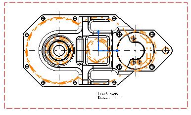
349
350 Generate Parameters Generate parameters are located in the Drafting -> Generate nodes of the generative view style XML file. They specify whether the elements should be projected in the view. Parameter Value Description Remark AxisLines CenterLines Fillets HiddenLines Threads 3DPoints Yes/No Yes/No None / Boundaries / OriginalEdges / ProjectedOriginalEdges Yes/No Yes/No Yes/No Specifies whether axis lines should be projected. Specifies whether center lines should be projected. Defines the fillet representation mode. Specifies whether hidden lines should be projected. Specifies whether threads should be projected. Specifies whether 3D points should be projected. For more information on axis lines, please refer to Properties available on Generative Views in the Editing View Properties section. For more information on center lines, please refer to Properties available on Generative Views in the Editing View Properties section. For more information on fillets, please refer to Properties available on Generative Views in the Editing View Properties section. For more information on hidden lines, please refer to Properties available on Generative Views in the Editing View Properties section. For more information on threads, please refer to Properties available on Generative Views in the Editing View Properties section. For more information on 3D points, please refer to Properties available on Generative Views in the Editing View Properties section.
351 Wireframe Yes/No Specifies whether wireframe should be projected. For more information on wireframe, please refer to Properties available on Generative Views in the Editing View Properties section. Replaced by 3DInheritance parameters in styles provided since V5R12. Using3DColors Using3DSpec Yes/No Yes/No Specifies whether colors defined in 3D should be kept. Specifies whether Drafting specifications applied to assembly instances (cut, use, hidden lines) should be used. For more information on 3D colors, please refer to Properties available on Generative Views in the Editing View Properties section. For more information on 3D Spec, please refer to Properties available on Generative Views in the Editing View Properties section.
352 View Dress-Up parameters View dress-up parameters are located in the Drafting -> ViewDressup nodes of the generative view style XML file (available in Tools -> Standard -> generativeparameters category -> *.XML file). They define the style of the various parameters which deal with the dress-up of the view. There are various kinds of dress-up parameters: Operators 3D Inheritance GeneratedGeometry Operators Parameter Parameter Name Value Description Color color Determines the color of the section profile. Section Linetype integer Determines the linetype used for the section profile. Thickness integer Determines the line thickness used for the section profile. Section -> SkinSection The section profile parameter is displayed in red. Color color Determines the color of the skin section profile. Linetype integer Determines the linetype used for the skin section profile. Thickness integer Determines the line thickness used for the skin section profile.

353 Section -> SolidSection Color color Determines the color of the solid section profile. Linetype integer Determines the linetype used for the solid section profile. Thickness integer Determines the line thickness used for the solid section profile. Detail Color color Determines the color of the detail profile. Linetype integer Determines the linetype used for the detail profile. Thickness integer Determines the line thickness used for the detail profile.

354 Break Color color Determines the color of the break profile. Linetype integer Determines the linetype used for the break profile. Thickness integer Determines the line thickness used for the break profile. Breakout Color color Determines the color of the breakout profile. Linetype integer Determines the linetype used for the breakout profile. Thickness integer Determines the line thickness used for the breakout profile.

355 3DInheritance Parameter Parameter Name Value Description Color yes/no Specifies whether wireframe color should be inherited from 3D. Wireframe Linetype yes/no Specifies whether wireframe linetype should be inherited from 3D. Thickness yes/no Specifies whether wireframe thickness should be inherited from 3D. Solid Color yes/no Specifies whether solid color should be inherited from 3D. Linetype yes/no Specifies whether solid linetype should be inherited from 3D. Thickness yes/no Specifies whether solid thickness should be inherited from 3D. 3D Points Color yes/no Specifies whether 3D points color should be inherited from 3D. Symbol yes/no Specifies whether 3D points symbol should be inherited from 3D.

356 GeneratedGeometry Parameter Parameter Name Value Description Color color Determines the color of vivid edges. VividEdges Linetype integer Determines the linetype used for vivid edges. Thickness integer Determines the line thickness used for vivid edges.

357 HiddenEdges Color color Determines the color of hidden edges. Linetype integer Determines the linetype used for hidden edges. Thickness integer Determines the line thickness used for hidden edges.

358 Fillets Color color Determines the color of fillets. Linetype integer Determines the linetype used for fillets. Thickness integer Determines the line thickness used for fillets.

359 Wireframe Color color Determines the color of wireframe. Linetype integer Determines the linetype used for wireframe. Thickness integer Determines the line thickness used for wireframe.

360 3DPoints Symbols integer Determines the symbol used for 3D points. Use O to inherit from the 3D symbol, use 1 to 8 to choose a custom symbol.

361 How are dress-up parameters computed?
362
363 Drafting Interoperability In this section, you will find information on working with Drafting and the PDM systems listed below. Working with ENOVIA LCA Working with ENOVIA VPM
364 Working with ENOVIA LCA Managing CATDrawing Documents in ENOVIA LCA Optimal CATIA PLM Usability for Drafting
365 Managing CATDrawing Documents in ENOVIA LCA This task shows you how to manage the integration between CATIA V5 Drafting and ENOVIA LCA. You will learn how to: create a CATDrawing document and save it in ENOVIA LCA retrieve the CATDrawing document in ENOVIA LCA view the documents which impact the CATDrawing in ENOVIA LCA open the CATDrawing document in CATIA V5 This task uses an assembly drawing (i.e. a drawing with views generated from a CATProduct document) as an example, but the same possibilities apply to part drawings as well. For more information about interoperability between CATIA and ENOVIA LCA, refer to the ENOVIA-CATIA Interoperability User's Guide. For more information on using ENOVIA LCA, refer to ENOVIA V5 LifeCycle Applications documentation. Have a CATIA V5 and an ENOVIA LCA sessions running. Creating a CATDrawing document and saving it in ENOVIA LCA 1. In ENOVIA LCA Product Class View, select a product and send it to CATIA V5. For more information, refer to Sending an ENOVIA LCA Document to CATIA V5 in the ENOVIA-CATIA Interoperability User's Guide. 2. In CATIA V5, select Start -> Mechanical Design -> Drafting. The New Drawing Creation dialog box is displayed. 3. Select the views to be automatically created on your drawing, for example the Front, Top and Left icon. 4. Click OK. A progress bar appears while the views are being generated from the opened CATProduct. The views are then displayed in the CATDrawing document.
366 5. Click the Save Data in ENOVIA LCA Server... icon to save the drawing in ENOVIA LCA. The Save in ENOVIA LCA dialog box is displayed. For more information, refer to Saving an ENOVIA LCA Document from CATIA V5 in the ENOVIA-CATIA Interoperability User's Guide. 6. Click OK to validate. The drawing is vaulted in ENOVIA, as well as the parts and products from which the views were generated. Note that the drawing is saved as a document in ENOVIA, it is not attached to a part at this moment. Retrieving the CATDrawing document in ENOVIA LCA 1. In ENOVIA LCA, click the Search icon in the left-hand pane to perform a query in order to retrieve your CATDrawing document. 2. Select Content Management -> Documents -> Documents. The Search panel is displayed. 3. In the Search panel, enter the name of your CATDrawing document and click OK. The search results are displayed in the bottom pane. 4. Right-click the CATDrawing document and select Copy from the contextual menu. 5. In ENOVIA LCA Product Editor, paste the document under the PRC. Viewing the documents which impact the CATDrawing in ENOVIA LCA
 to expand the whole view of the product.")
.")
367 1. In ENOVIA LCA Content Management, right-click the CATDrawing document (it can be either a part drawing or an assembly drawing) and select Send To -> Impacted By. The Impacted By Tree View is displayed. 2. Double-click the CATDrawing document (here P2) to expand the whole view of the product. The drawing dependencies are displayed, letting you view the links between the CATDrawing document and the CATPart and/or CATProduct documents it references. This also lets you know whether the drawing is up-to-date or not. In the examples below, P2 identifies the drawing, and the ENOVIA_VPMTPDependence object identifies the drawing dependence(s). Example 1 The color of the ENOVIA_VPMTPDependence object relates to the status of its dependences (here P1 and Property of P1): ENOVIA_VPMTDependence is green, which means that it is synchronized with its dependences. The thumb relates to the status of the branch: here the thumbs are up and green, which means that P1 and Property of P1 are synchronized with the ENOVIA_VPMTPDependence object. Since all elements are synchronized, the drawing is up-to-date. Example 2 You can see that ENOVIA_VPMTDependence is red, which means that it is not synchronized with its dependences. Here, the red thumb down for P1 shows that it has been modified: it is not synchronized with the ENOVIA_VPMTDependence object. Therefore, ENOVIA_VPMTDependence is not synchronized with P1 either: it is red. Since not all elements are synchronized, the drawing is not up-to-date.
368 3. If the drawing is not up-to-date, you can update it using the following method: a. Open the CATDrawing document in CATIA V5 (as described in Opening the CATDrawing document in CATIA V5 below). b. Refresh it using the update icon. c. Save it using the Save Data in ENOVIA LCA Server... icon. d. Perform a local refresh in ENOVIA LCA using the Refresh icon. If you now go back to the Impacted By Tree View in ENOVIA LCA, the drawing is indicated as being up-to-date. For more information, refer to Publishing Links in ENOVIA LCA in the ENOVIA-CATIA Interoperability User's Guide. Opening the CATDrawing document in CATIA V5 To be able to open only the CATDrawing document in CATIA V5, you need to send it from ENOVIA Content Management for example. To illustrate this task, you should use an assembly drawing (rather than a part drawing). 1. In ENOVIA LCA Product Editor, right-click the CATDrawing document and select Send To -> Content Management. 2. In Content Management, right-click the CATDrawing document and select Send To -> CATIA V5. The drawing is displayed in CATIA V5. In the case of an assembly drawing, the drawing links are broken. 3. To solve the links, perform as follows, depending on the save mode you chose when saving the assembly in ENOVIA LCA: For an exploded assembly (i.e. saved as Document not kept & Product Structure Exposed): right-click the drawing in the specification tree and select Load PDM Context (you can also go back to ENOVIA LCA, right-click the associated CATProduct and CATPart documents in Content Management, and select Send To -> CATIA V5). This loads the assembly drawing context (i.e. the CATProduct and CATPart documents used for the assembly drawing creation or for the last assembly drawing update) in the Product Structure editor in CATIA V5. Note that the part instances which were not referenced by the drawing when you last saved it are not loaded. For a "black box" or "work package" assembly (i.e. saved as Document kept in vault & Publications Exposed): select Edit -> Links... and choose the Pointed documents tab to visualize the links between the CATProduct and CATDrawing documents. From the list of pointed documents, select the CATProduct and/or CATPart documents you want to open, and click the Open button. This loads the selected documents in the Product Structure editor in CATIA V5. Note that you need to load all the parts which make up a given product if you want them to be included in the drawing views at the next update.
369 The drawing links are now solved. The Drafting specification tree indicates whether the drawing is up-to-date or not, whether the drawing is a part drawing or an assembly drawing. If a 3D element (product or part) has been modified before launching the drawing, the update mask appears in front of the drawing elements which need an update (all, in our example): If no modification has been performed in 3D before launching the drawing, the various drawing elements in the specification tree are shown as being up-to-date:
370 Optimal CATIA PLM Usability for Drafting When working with Drafting in an ENOVIA LCA context, there are a few circumstances under which a drawing cannot be correctly saved in ENOVIA LCA. More specifically, a drawing from an exploded product (i.e. an assembly saved as Document not kept & Product Structure Exposed) cannot be saved in the following cases: when the drawing contains views referencing different instances of the exploded product: indeed, all generated views in the drawing must reference the same 3D elements. when the drawing contains views referencing the following DMU components: 3D box or section. when the drawing contains text files referencing knowledgeware attributes. An error message is now displayed when trying to create views referencing such elements. Note that this message is only displayed if the product from which you are trying to create the view has already been saved in the ENOVIA LCA database.
371 Working with ENOVIA VPM Managing CATDrawing Documents in ENOVIA VPM Optimal CATIA PLM Usability for Drafting
372 Managing CATDrawing Documents in ENOVIA VPM This task shows you how to manage the integration between CATIA V5 Drafting and ENOVIA VPM. You will learn how to: create a CATDrawing document and save it in ENOVIA VPM view the documents which impact the CATDrawing in ENOVIA VPM open the CATDrawing document in CATIA V5 For more information about interoperability between CATIA and ENOVIA VPM, refer to the ENOVIA-CATIA Interoperability User's Guide. For more information on using ENOVIA VPM, refer to ENOVIA VPM documentation. Have a CATIA V5 and an ENOVIA 3d com Navigator sessions running. Creating a CATDrawing document and saving it in ENOVIA VPM 1. From the ENOVIA 3d com Navigator, right-click a CATPart or a CATProduct document and select CATIA_V5 - > Load to load this document into CATIA V5. For more information, refer to the CATIA V5 / ENOVIA VPM Interoperability via ENOVIA 3d com on Windows chapter in the ENOVIA-CATIA Interoperability User's Guide. Note that to create a subassembly drawing, the ENOVIA VPM subassembly has to be loaded into CATIA V5 from its own bookmark in the ENOVIA 3d com Navigator web tree. 2. In CATIA V5, select Start -> Mechanical Design -> Drafting. The New Drawing Creation dialog box is displayed. 3. Select the views to be automatically created on your drawing, for example the Front, Top and Left icon.
373 4. Click OK. A progress bar appears while the views are being generated from the opened CATPart or CATProduct document. The views are then displayed in the CATDrawing document. 5. Create an ENOVIA VPM document with the CATDrawing document, as explained in Creating an ENOVIA VPM Document in CATIA V5 in the ENOVIA-CATIA Interoperability User's Guide.
 and select Impact As Reference.")
374 Viewing the documents which impact the CATDrawing in ENOVIA VPM 1. From the ENOVIA 3d com Navigator, right-click the CATDrawing document (it can be either a part drawing or an assembly drawing) and select Impact As Reference. An impact graph for the drawing is launched in the ENOVIA 3d com Navigator webspace. 2. Double-click the drawing box (here 2BB-DWG --- AC) to visualize reference-to-reference links for the CATDrawing document. The drawing dependencies are displayed, letting you view the links between the CATDrawing document and the CATPart and/or CATProduct documents it references. The impact graph also lets you know whether the drawing is up-to-date or not: a green thumb up means that the drawing is synchronized with the documents it references, and therefore up-to-date. For example, in the case of an up-to-date part drawing, you may get something like the following impact graph:
375 a red thumb down means that the drawing is not synchronized with the documents it references, and therefore not up-to-date. For example, in the case of a not-up-to-date part drawing, you may get something like the following impact graph: 3. If the drawing is not up-to-date, you can update it using the following method: a. Open the CATDrawing document in CATIA V5 (as described in Opening the CATDrawing document in CATIA V5 below). b. Refresh it using the update icon. c. Save it in ENOVIA VPM using File -> Save. If you now go back to the Impacted By Tree View in ENOVIA LCA, the drawing is indicated as being up-todate. For more information, refer to Using CATIA V5 Multimodel Link Dependencies in the ENOVIA-CATIA Interoperability User's Guide. Opening the CATDrawing document in CATIA V5 To illustrate this task, you should use an assembly drawing (rather than a part drawing). 1. From the ENOVIA 3d com Navigator, right-click the CATDrawing document and select CATIA_V5 -> Load to load this document into CATIA V5. The drawing is displayed in CATIA V5. In the case of an assembly drawing, the drawing links are broken. 2. To solve the links, perform as follows, depending on the save mode you chose when saving the assembly in ENOVIA VPM: For an exploded assembly: right-click the drawing in the specification tree and select Load PDM Context (you can also go back to ENOVIA 3d com Navigator, right-click the associated CATProduct and CATPart documents in Content Management, and select
376 CATIA_V5 -> Load). This loads the assembly drawing context (i.e. the CATProduct and CATPart documents used for the assembly drawing creation or for the last assembly drawing update) in the Product Structure editor in CATIA V5. Note that the drawing has to be placed in the assembly and that the part instances which were not referenced by the drawing when you last saved it are not loaded. For a "black box" or "work package" assembly: select Edit -> Links... and choose the Pointed documents tab to visualize the links between the CATProduct and CATDrawing documents. From the list of pointed documents, select the CATProduct and/or CATPart documents you want to open, and click the Open button. This loads the selected documents in the Product Structure editor in CATIA V5. The LoadPDM command will not load the technological package referenced by the drawing. The referenced technological packages can be listed via the Edit Links command, and have to be opened from LCA sessions. A drawing references technological packages if it contains views created by selecting FT&A views stored in a technological package (View from 3D command). Note that you need to load all the parts which make up a given product if you want them to be included in the drawing views at the next update. The drawing links are now solved. The Drafting specification tree indicates whether the drawing is up-todate or not, whether the drawing is a part drawing or an assembly drawing. If a 3D element (product or part) has been modified before launching the drawing, the update mask appears in front of the drawing elements which need an update (all, in our example): If no modification has been performed in 3D before launching the drawing, the various drawing elements in the specification tree are shown as being up-to-date:
377 Optimal CATIA PLM Usability for Drafting When working with Drafting in an ENOVIA VPM context, there are a few circumstances under which a drawing cannot be correctly saved in ENOVIA VPM. More specifically, a drawing from an exploded product (i.e. an assembly saved as Document not kept & Product Structure Exposed) cannot be saved in the following cases: when the drawing contains views referencing different instances of the exploded product: indeed, all generated views in the drawing must reference the same 3D elements. when the drawing contains views referencing the following DMU components: 3D box, section and scenes. when the drawing contains texts with links to an attribute stored in a technological package. An error message is now displayed when trying to create views referencing such elements. Note that this message is only displayed if the product from which you are trying to create the view has already been saved in the ENOVIA VPM database.

378 Workbench Description This section contains the list of the icons and menus specific to Generative Drafting workbench. You may read these pages whenever you require more detailed information on these commands which have been documented in other parts of the guide. Menu Bar Generative Drafting Toolbars CATDrawing Specification Tree Icons

379 Menu Bar In this chapter we will describe the various menus, submenus and items specific to the Generative Drafting workbench. File For... See... Page Setup... Defining the Drafting Sheet Print... Printing a Sheet Printer Setup... Printing a Sheet Edit For... See... Links Editing Drawing Links Not Aligning a View

380 Properties Background Access and edit information on 2D geometry, dress-up elements, annotations and dimensions in a single dialog box Creating a Frame Title Block Insert For... See... Views Drawing Dimensioning Generation Annotations Creating Views Creating Sheets Creating Dimensions Generating Dimensions Annotations Dress Up Dress-Up Elements

381 New sheet Define a Drafting Sheet New Detail Sheet Create a 2D component New View Instantiate Detail Create views Re-use a 2D component

382 Dimensions Create dimensions Cumulated Dimensions Create cumulated dimensions Stacked Dimensions Create stacked dimensions Length/Distance Dimensions Create explicit dimensions Angle Dimensions Create explicit dimensions Radius Dimensions Create explicit dimensions Diameter Dimensions Create explicit dimensions Chamfer Dimensions Create chamfer dimensions


383 Coordinate Dimensions Create coordinate dimensions Create Interruption Interrupt one or more extension lines Remove Interruption Interrupt one or more extension lines Remove all Interruptions Interrupt one or more extension lines Datum Feature Geometrical Tolerance Create a datum feature Create a geometrical tolerance Generating Dimensions Generate dimensions in one shot

384 Generating Dimensions Step by Step Generate dimensions semi-automatically Balloon generation Generating Associative Balloons Bill of material Add a generative Bill of Material Text Create a free text Text with Leader Create a text with a leader Text Replicate Replicate a text attribute Balloon Datum Target Create a balloon Create a datum target Roughness Symbol Create a roughness symbol Welding Symbol Create a welding symbol
 Axis Line Create axis lines Axis Line and Center Line Create axis lines and center lines Tools For... See... Positioning Further down Analyze Further down")
385 Weld Create a geometry weld Center Line Create center lines (no reference) Center Line with Reference Create center lines (reference) Thread Create threads (no reference) Thread Create threads (reference) Axis Line Create axis lines Axis Line and Center Line Create axis lines and center lines Tools For... See... Positioning Further down Analyze Further down
 Line up dimensions (reference) Dimension Positioning Position")
386 Reset All Defaults Before You Begin: Insert File Exporting and Importing a File Element Positioning Modifying annotation positioning Line-up Line up dimensions (free space) Line up dimensions (reference) Dimension Positioning Position dimensions
387 Show Geometry in All Viewpoints Showing Geometry in Views Dimensions Analysis Analyzing Interfering Dimensions
388 Generative Drafting Toolbars This section describes the various icons of the Generative Drafting workbench. The toolbars are located on each side of the workbench in the default set-up. A number of toolbars available in the Generative Drafting workbench are actually part of the Interactive Drafting workbench. These toolbars are also listed below but they are documented in the Interactive Drafting User's Guide. Generative Drafting Toolbar Drawing Views Generative View Style Dimension Generation Interactive Drafting Toolbar Dimensioning Annotations Dress-Up Tools Tools Palette Geometry Creation Geometry Modification Properties Text Properties Graphic Properties Dimension Properties Style Purpose Create sheets, views, 2D components and frame title blocks Create different kinds of views Specify the generative view style that should be used when creating views Generate dimensions and balloons Purpose Create all types of dimensions needed for your drawing Add annotations to existing views by creating them Add dress-up elements on the drawing Activate display and positioning tools Use specific options or value fields available for a given command Create geometry Transform existing 2D elements and add constraints to elements on the drawing Modify the text properties Modify the graphic properties of all kind of features Modify the dimensions properties Set the style that will be used to create a new object
389 Drawing See Manipulating the Drafting Sheet See Creating a 2D Component See Re-using a 2D component See Creating a 2D Component See Add a generative Bill of Material
390 Views See Creating a Front View See Creating an Advanced Front View See Creating an Unfolded View See Creating Projection Views See Creating an Auxiliary View See Creating an Offset Section View/Offset Section Cut See Creating an Offset Section View/Offset Section Cut See Creating an Aligned Section View/Aligned Section Cut See Creating an Aligned Section View/Aligned Section Cut See Creating a Quick Detail View/Quick Detail View Profile See Creating a Detail View/Detail View Profile
391 See Creating a Detail View/Detail View Profile See Creating a Clipping View See Creating a Clipping View See Creating an Isometric View See Creating a Broken View See Creating a Breakout View See Creating Views via the Wizard See Creating Views via the Wizard
392 See Creating a View using Generative View Styles Generative View Style
393 Dimension Generation See Dimensions Generation in One Shot See Semi-automatic Dimension Generation See Generating Balloons
394 CATDrawing Specification Tree Icons This section describes the various icons of the Interactive Drafting and Generative Drafting workbenches. Current drawing Design sheet Detail sheet 2D component View. Applies to interactive views only (whatever the view type is). Front view. Applies to generative views only. Projection view. Applies to generative views only. Auxiliary view. Applies to generative views only. Isometric view. Applies to generative views only. Section view. Applies to generative views only. Section cut. Applies to generative views only. Detail view. Applies to generative views only. Unfolded view. Applies to generative views only. Masks Specific to Drafting Applications Unreferenced drawing. The link between the drawing and the 3D part or product is broken. Does not apply to drawings which contain only interactive views. Unreferenced sheet. The link between the sheet and the 3D part or product is broken. Does not apply to sheets which contain only interactive views. Unreferenced view. The link between the view and the 3D part or product is broken. Does not apply to interactive views. Locked view. (Note that a locked view cannot be updated. Therefore, locked views which are not up-todate will not be applied the corresponding mask.)
395 Customizing This section explains how to customize settings and toolbars for Drafting workbenches. Customizing Settings Customizing Toolbars
396 Customizing Settings Before you start your first working session, you can customize the way you work to suit your habits. This type of customization is stored in permanent setting files: these settings will not be lost if you end your session. Note that some settings apply to Generative Drafting only, while others apply to Interactive Drafting only. Such cases are specified. 1. Select Tools -> Options. The Options dialog box is displayed. 2. Choose the Mechanical Design category in the left-hand box. 3. Select the Drafting sub-category. Various tabs are displayed. General lets you set general settings to be used in the Generative Drafting workbench. Layout lets you customize options that will be used when creating views or when adding sheets. View lets you customize geometry, dress-up and view generation options that will be used when generating views (Generative Drafting workbench only). Generation lets you customize options for controlling dimension and annotation generation (Generative Drafting workbench only). Geometry lets you customize options that will be used when creating 2D geometry, whether using autodetection (or SmartPick) or not, or still adding constraints to this geometry. Dimension lets you customize options that will be used when creating or re-positioning dimensions. Manipulators lets you visualize options that will be used for manipulators whenever creating or modifying dimensions (Interactive Drafting workbench only). Annotation and Dress-Up lets you customize options that will be used when creating annotations. Administration lets you customize options for the management of drawings. 4. Two other tabs, located in the General category, Display sub-category, also interfere with Drafting: Thickness & Font lets you set thickness properties. Linetype lets you set linetype properties. 5. Set options in these tabs according to your needs. 6. Click OK in the Options dialog box when done.
397 General This page deals with the following categories of options in the General tab: Ruler Grid Rotation Colors Tree View Axis Ruler Show ruler Select this option to display the ruler in your sheet. It means you visualize the cursor coordinates as you are drawing. By default, this option is not selected. Grid
398 Display Select this option to display the grid in your session. You will note that this capability is also available via the Drafting Options toolbar. By default, this option is selected. Snap to point Select this option if you want the geometry to begin or end on the various intersection points of the grid. By default, this option is selected. Allow Distortions Select this option to apply different graduations and spacing between H and V. By default, this option is selected. Primary spacing: H & V The Primary spacing field lets you define the spacing between the major lines of the grid. To define your grid, enter the values of your choice in the H and/or V fields. By default, primary spacing is set to 100 mm. Graduations / H & V The Graduations field lets you set the number of graduations between the major lines of the grid, which actually consists in defining a secondary grid. To define your grid, enter the values of your choice in the H and/or V fields. By default, graduations are set to 10. Rotation
399 Rotation Snap Angle Specify the angle that should be used when rotating text elements (text, frame, or leader) using snapping. In other words, this option defines the snapping value used when rotating an element using the Select or Rotate commands. By default, rotation snap angle is set to 15 deg. Automatic Snapping Select this option to use snapping automatically when rotating an element. By default, this option is not selected. Colors (for pre-v5r14 drawings) From V5R14 drawings, sheet and detail backgrounds colors are defined in the standard file, under the node Sheet colors of General node. Sheet background Choose the color that will be used for the sheet background. By default, the color is white. Detail background Choose the color that will be used for the background of 2D components. By default, the color is white. Graduated color If you want the sheet background and/or the detail (i.e. 2D component) background to be graduated, select the associated box. By default, these options are not selected.
400 Tree Display parameters Select this option to display in the specification tree the formula parameters used in the drawing. By default, this option is selected. Display relations Select this option to display in the specification tree the relation parameters used in the drawing. By default, this option is selected. View axis Display in the current view Select this option if you want the view axis to be displayed when you activate a view. By default, this option is selected. Zoomable Select this option if you want to be able to zoom view axes (as you can do with geometry). By default, this option is selected. Reference size
401 Enter the size that you want to use as a reference to display view axes size. By default, the reference size is 30 mm.

402 Layout This page deals with the following categories of options in the Layout tab: View Creation New Sheet Background View Section / Projection Callout View Creation View name Select this option if you want the view name to be created automatically when creating views. By default, this option is selected. Scaling factor Select this option if you want the scaling factor to be created automatically when creating views. By default, this option is selected. View frame Select this option if you want the view frame to be created automatically when creating views. By default, this option is selected.

403 Propagation of broken and breakout specifications Select this option if you want broken and breakout specifications to be reproduced. By default, this option is not selected. Auxiliary and section views orientation according to profile You can decide if auxiliary and section views will be oriented according to the profile. In this case, the X axis will be parallel to the profile. By default, this option is not selected. View axis system based on 3D axis system Select this option if you want the axis system of the generated view to be based on the axis system of the 3D part. This enables you to create views with the same orientation if, when creating two views in the same projection plane by selecting two different faces, the axis systems which are specific to these faces are different. For example, take the following part: With the View axis system based on 3D axis system option not checked, the view orientation will be different depending on the element selected in the 3D when creating the view:
404 View orientation when a face of the rectangular pad is selected View orientation when a face of the elliptic pad is selected View orientation when the absolute XY plane is selected With the View axis system based on 3D axis system option checked, the view orientation will always be the same, no matter what element is selected in the 3D when creating the view: View orientation when either a face of the rectangular pad, a face of the elliptic pad, or the absolute XY plane is selected By default, this option is not selected. New sheet
405 Copy background view Select this option if you want a background view to be copied into newly created sheets. By default, this option is selected. Source sheet Specify whether you want the source sheet for the background view to be the first sheet of the current drawing, or a sheet from another drawing by selecting the appropriate option. By default, the option is First sheet. Background view Directory for frame and title block You can specify the path to the directory containing the frame and title block macros. By default, the path is install_root/vbscript/frametitleblock. Section/Projection Callout
406 Size not dependent on view scale Select this option if you do not want the size of projection and section callout elements to be dependent on the view scale. This option will apply to newly created callouts, i.e. selecting this option will not have any impact on existing callouts. Note that this option only applies to drawings created with versions prior to V5 R11 (i.e. versions up to V5 R10). By default, this option is selected.

407 View This page deals with the following categories of options in the Layout tab: Geometry generation / Dress-up View generation These options apply to the Generative Drafting workbench only. These options are also available as view properties, in the Properties dialog box for each view: from the contextual menu, click Properties, click the View tab and then select the desired options. Once you apply these options to a newly created view, you can only modify the view settings from the Properties dialog box. For more information, refer to Editing View Properties section in the Interactive Drafting User's Guide. Geometry generation / Dress-up This category of options lets you specify what kind of geometry and dress-up elements you want to generate when generating views.
408 Generate axis Select this option to generate axis lines. By default, this option is not selected. Generate threads Select this option to generate threads. By default, this option is not selected. Generate center lines Select this option to generate center lines. By default, this option is not selected. Generate hidden lines Select this option to generate hidden lines. By default, this option is not selected. Generate fillets Select this option to generate fillets. By default, this option is selected. Additionally, click the Configure button to configure fillet generation. You can choose to generate either of the types of fillets described below. By default, Boundaries is selected.
409 Boundaries Thin lines, representing the mathematical limits of the fillets. Boundaries will not be projected if they correspond to two faces which are continuous in curvature. They will be projected only if they correspond to a smooth edge which is situated between two faces whose curvature radii vary. This mode will be used automatically to represent a connection between two faces which are not joined by a fillet, no matter what option you select. Symbolic Original edges, projected in a direction that is normal to each corresponding surface. Approximated Original Edges Original edges, at the intersection of the two surfaces joined by the fillet. Projected Original Edges Original edges, projected on fillet surfaces in the direction of the view projection. This projection mode is equivalent to the CATIA V4 fillet projection mode. The following restrictions apply to Symbolic, Approximated Original Edges and Projected Original Edges: Dimensions on such fillets are not associative. Such fillets cannot inherit 3D colors (see below). Likewise, when using generative view styles, such fillets cannot inherit the 3DInheritance view dress-up parameters (defined in Tools -> Standard -> generativeparameters -> *.XML file, Drafting -> ViewDressup -> 3DInheritance).
410 Inherit 3D colors Select this option if you want the colors of a part to be automatically generated onto the views. In the case of white parts, the views generated with this option selected will be white, and will therefore not be displayed properly. By default, this option is not selected. Project 3D Wireframe Select this option to visualize both the wireframe and the geometry on generated views. By default, this option is not selected. Additionally, click the Configure button to configure the 3D wireframe projection mode. You can choose whether projected 3D wireframe can be hidden (in some cases, depending on the projection angle, part or all of 3D wireframe will possibly be hidden) or is always visible (3D wireframe will be visible in all cases, independently of the projection angle). By default, Can be hidden is selected. Project 3D Points Select this option to project points from 3D (no construction element). By default, this option is not selected. Additionally, click the Configure button to select the type of points visualized in the projected drawing. In the 3D Point Projection dialog box, you can choose between keeping the symbols that are used in the 3D or using a new symbol.
 will be applied in the view.")
411 By default, the X symbol is selected. Apply 3D specification Select this option to specify whether, in an assembly, the properties assigned to given parts (also called components) will be applied in the view. The following 3D specifications may be defined for components in the Product Structure workbench: The component will, or will not, be cut when projected in section views (Do not cut in section views). The component will, or will not, be projected in views (Do not use when projecting). The component will, or will not, be represented with hidden lines (Represented with hidden lines). For more information, refer to Modifying Component Properties in the Product Structure User's Guide. By default, this option is selected.
. In the Linetype and thickness dialog box, select the line type and the thickness you want for each type of view, from the associated fields.")
, note that this linetype is just a graphical dress-up of the view.")
412 View Linetype Click the Configure button to configure linetypes and thicknesses for specific types of views: section view, detail view, broken view, breakout view, skin section view (in the case of wireframes and surfaces). In the Linetype and thickness dialog box, select the line type and the thickness you want for each type of view, from the associated fields. Click Close when you are done. By default, linetypes and thicknesses are configured as shown above. If you choose the zigzag linetype (linetype #8), note that this linetype is just a graphical dress-up of the view. This means that if one line is relimited on the breakout line, then it will be relimited on the theoretical line as shown here, and not on the visualized zigzag line. View generation
413 View generation mode From this list, select how you want to generate views. By default, Exact view is selected. Exact view Generates exact views from the Design mode, i.e. views for which the geometry is available. The exact generation mode will be the best option in most cases: This is the fastest generation mode. All types of views can be generated using this option. All functionalities (dress-up, dimensions, annotations, etc.) are available. However, there are a few cases in which choosing the exact generation mode will not be appropriate: In the case of sophisticated products or assemblies involving large amounts of data, generating exact views may consume too much memory. Polyhedral elements (such as dittos, surfaces, etc.) from V4.model documents are not supported. CGR Generates views using the CGR format (CATIA Graphical Representation). CGR corresponds to a data format containing a graphical representation of the geometry only, which is available with the Visualization mode (as opposed to the exact geometry, which is available with the Design mode). With CGR, only the external appearance of the component is used and displayed; the geometry is not available. The corresponding.cgr file, if it exists, is inserted from the cache system. CGR views are not as high in quality as exact views, but they consume much less memory during the generation. This may be useful when dealing with sophisticated products or assemblies involving large amounts of data. However, this generation mode is rather slow. For more information about the advantages and restrictions associated with the CGR generation mode, see Advantages and restrictions common to CGR and Approximate modes below.
414 Approximate You can now generate views in Approximate mode. Although Approximate views are not as high in precision and quality as exact views, this generation mode dramatically reduces memory consumption. Performances may also be improved, depending on how you fine-tune precision. Therefore, the Approximate mode is particularly well-adapted to sophisticated products or assemblies involving large amounts of data. The Approximate mode offers about the same advantages and restrictions than the CGR generation mode (see above). However, there are some differences: Approximate consumes even less memory than CGR. Approximate is faster than CGR, but performances largely depend on fine-tuning. Approximate provides more approximate results than CGR, but these results largely depend on how you fine-tune precision. You can fine-tune the generation options according to your needs. Click the Configure button. In the dialog box, move the cursor to set the precision (i.e. the level of detail - LOD) with respect to the performances (i.e. generation time - Time). The level of detail corresponds to the precision with which the application determines which edges are hidden and which are not. As a result, decreasing this precision may lead to smaller geometry being visible whenever it should not be, and vice-versa. The higher the precision, the lower the performances. In any case, memory consumption will not be impacted. Click Close when you are done. For more information about the advantages and restrictions associated with the Approximate generation mode, see Advantages and restrictions common to CGR and Approximate modes just below. Advantages and restrictions common to CGR and Approximate Using CGR or Approximate to generate views offers the following advantages: Optimize memory consumption when generating and handling projection views for large products or assemblies. Generate views from third-party data (such as MultiCAD), as well as from polyhedral elements (such as dittos, surfaces, etc.) in V4.model documents. However, the CGR or Approximate generation mode involves a number of restrictions: You cannot generate section views, section cuts, detail views, detail view profile, breakout views, unfolded views and views from 3D. You cannot project 3D elements such as wireframe, points, etc. on CGR or Approximate views. CGR or Approximate views cannot contain dress-up elements (axis, center lines, threads). Auxiliary view profiles, annotations, dimensions, etc. are not associative on CGR or Approximate views. CGR or Approximate views being only a graphical representation of the geometry, only line segments are generated in such views. As dimensions are not associative, the only elements that can be dimensioned are these line segments.
415 As a result, it is impossible to create certain types of radius or diameter dimensions in such views; to put it simply, you cannot create radius and diameter dimensions on elements other than these line segments. As a consequence of these restrictions, selecting either the CGR or the Approximate option disables a number of other options on the View and on the Generation tab. Raster Generates views as images. This enables you to quickly generate overall views for large products or assemblies, regardless of drawing quality. Such views are associative to the 3D geometry and can be updated when the part or product changes. Raster views offer a number of restrictions: You cannot generate the following types of views using this option: view from 3D, section views, section cuts, detail views, breakout views, unfolded views. Raster views cannot contain dress-up elements (axis, center lines, threads). Creating dimensions is impossible. Generally speaking, all commands requiring the selection of geometry are not available. Raster views cannot be edited (you can work around this by isolating the view: double-clicking the image will then launch an image editor). As a consequence of these restrictions, selecting this option disables a number of other options on the View and on the Generation tab. To optimize disk space and memory consumption, it is recommended that you do not select the Inherit 3D colors option when generating views as images. Click the Configure button to configure the raster mode options. From the Mode list, select the mode that you want to use: Dynamic Hidden Line Removal, Shading, Shading with edges. These modes are equivalent to the 3D rendering styles. For more information, refer to Using Rendering Styles in the Infrastructure User's Guide. Now, set the level of detail (i.e. the definition, in dpi) that will respectively be used to visualize and to print the drawing. You can choose between three pre-defined modes (Low quality, Normal quality and High quality) and a custom mode (Customize). If you choose to customize the definition yourself, set the dpi for visualization and for print in the appropriate fields. Click Close when you are done.

416 The level of detail applies to the scale of the view. In some cases (when the view would print with a considerable height or width), there may be too many pixels to generate the view. In this case, the view will be displayed as a red cross-mark. If this happens, try to reduce the scale of the view and/or the level of detail. If you want the colors of a part to be used when generating Raster views using the Shading or Shading with edges mode, remember to select the Inherit 3D Colors option. Otherwise, the view will be generated using shades of grey. To further improve performance when generating Raster or CGR views, we recommend you work in Visualization mode: to do this, in the Options dialog box, go to Infrastructure -> Product Structure -> Cache Management tab and select Work with the cache system. (For more information, see Customizing Cache Settings in the Infrastructure User's Guide and Visualization mode in the Product Structure User's Guide.) By default, this option is not selected.
417 Exact preview for view generation Make sure this option is selected if you want an exact preview when generating views. As a result, the part or product will be loaded in Design mode when previewing the view to generate, even if you are working in Visualization mode. Deselect this option to get a quick preview of the 3D document when generating views. In this case, a part or product open in Visualization mode will not be loaded in Design mode for the preview, which optimizes memory consumption. By default, this option is selected. Only generate parts larger than To specify that you only want to generate parts which are larger than a certain size, select this option and indicate the appropriate size by providing a value in millimeters in the appropriate field. By default, this option is not selected. Enable occlusion culling Select this option if you want to save memory when generating exact views from an assembly which is loaded in Visualization mode (i.e. when the Work with the cache system option is active). This will load only the parts which will be seen in the resulting view (instead of loading all of them, which is the case by default), which optimizes memory consumption and CPU usage. To ensure the efficiency of this option, make sure that the Exact preview for view generation option is not selected. In the case of an assembly which is loaded in Design mode, or in the case of a part, the Enable occlusion culling option will help increase performance by reducing CPU usage. Keep the following restrictions in mind when selecting the Enable occlusion culling option: The Project 3D points option will be disabled. The only option available for Project 3D wireframe is Can be hidden.
.")
418 If you choose to project 3D wireframe, you will need to make sure that your wireframe elements have been taken into account when the CGR data was created: this is the case if you activated the Save lineic elements in cache option from Tools -> Options -> General -> Display -> Performances before the creation of CGR data (i.e. before you launched the part or product in Visualization mode). If not, you need to activate the Save lineic elements in cache option and then re-create the CGR data. To do this: 1. Close all open parts and products and exit the application. 2. Delete your CGR data from the cache. (The cache location is specified in Tools -> Options - > Infrastructure -> Product Structure -> Cache Management tab, Path to the local cache field.) 3. Re-open the product in Visualization mode. By default, this option is not selected. Select body in assembly Select this option if you want to be allowed to create a view selecting one or several bodies in an assembly. By default, the box is not checked and the following error message is displayed if you try to generate a view from a body. Once Select body in assembly is checked, a warning is displayed when creating the view as you are strongly advised not to use this option. Actually, generating a view on a body from a CATProduct prevents many features from working properly: Positioning of the different parts in the assembly is not taken into account in the resulting view and parts might be superimposed, Changes such as rotation or translation in the assembly are not taken into account, Modification of an instance properties such as visibility or colors are not taken into account, Overload properties is disabled as it is linked to the assembly's properties, Creation of balloons is not possible, Edit/ Links option references only two parts.
419 Moreover, multi-selecting a body in two different parts modifies the behavior of the Modify links and Modify Projection Plane according to the order of selection, since the CATPArt of the first selected body will be used as reference document and not the CATProduct. Clipping view Select this option if you want dimensions to be put automatically in no show mode for non-visible geometry in clipping view. Dimensions are put in no show mode only if both parent elements of the dimension are in the non-visible geometry. If only one parent element is impacted, the dimension turns to light blue. For more information, refer to the Dimension on geometry without 2D representation section. View From 3D Select this option if you want to keep 2D layout and dress-up modifications after an update. 2D dress-up modifications are kept when updating design changes from 3D. Associativity of the annotations or their leader with the 3D geometry is taken into account. Associativity between annotations is taken into account.

420 Generation This page deals with the following categories of options in the Generation tab: Dimension generation Balloon generation These options apply to the Generative Drafting workbench only. Dimension generation Generated dimensions are positioned according to the most representative views. In other words, a dimension will appear on a view so that it does not need to be created on another view. The dimensions are generated on the views on the condition the settings were previously switched to the dimension generation option. Generate dimensions when updating the sheet Select this option to generate dimensions automatically each time you update the sheet. By default, this option is not selected. Filters before generation Select this option to display the Dimension Generation Filters dialog box before generation. This enables you to specify what type of dimensions you want to generate. Also, in assembly or product views, this lets you indicate what parts you want to generate dimensions for. By default, this option is not selected.
421 Automatic positioning after generation Select this option if you want the dimensions to be automatically positioned after generation. By default, this option is not selected. Allow automatic transfer between views Select this option if you want dimensions to be automatically transferred to the most appropriate view when regenerating dimensions. By default, this option is not selected. Analysis after generation Select this option to display the Generated Dimension Analysis dialog box after generation. By default, this option is selected. Generate dimensions from parts included in assembly views Select this option to extract 3D part constraints (on top of assembly constraints) when generating product dimensions. This option is particularly useful if you want to generate dimensions for all parts included in assembly or product views, without displaying the Dimension Generation Filters dialog box before dimension generation. Note that if you display the Dimension Generation Filters dialog box before generating dimensions, you will need to indicate what parts you want to generate dimensions for (whether this option is selected or not). By default, this option is not selected. Delay between generations for step-by-step mode Specify the delay between each dimension generation when generating dimensions step by step. By default, this option is not selected. Balloon generation
422 Creation of a balloon for each instance of a product If you select this option, a balloon will be generated for each instance of a component: therefore, if a component is used two times within a product, then the balloon will be generated twice. If you leave this box unselected, a single balloon will be generated for all instances of the same component, when a component is used several times within a part or product. By default, this option is not selected.

423 Geometry This page deals with the following categories of options in the Geometry tab: Geometry Constraints creation Constraints Display Colors Geometry Create circle and ellipse centers You can decide whether or not you want to create centers when creating circles or ellipses. Click to clear this option if you do not need to create circle and ellipse centers. By default, this option is selected. Allow direct manipulation Select this option to be able to move geometry using the mouse. When moving geometry, you can move either the minimum number of elements, the maximum number of elements, or still the minimum number by modifying the shape of elements, if needed. Remember that a 2D component considered as a 2D geometry is also affected by this option. By default, this option is selected. Additionally, click the Solving mode... button to configure manipulation.

424 The dialog box that appears offers the following options as regards the solving mode: Standard mode You move as many elements as possible and also respect existing constraints. Minimum move You move as few elements as possible and also respect existing constraints. Relaxation You move elements by re-distributing them over the sketch, globally speaking. This method solves element moving by minimizing energy cost. Furthermore, you can choose to drag elements along with their end points by selecting Drag elements end points included. By default, Standard mode and Drag elements end points included are selected. Show H and V fields in the Tools Palette You can show the H and V fields in the Tools Palette when creating 2D geometry or when offsetting elements. Leaving the option unselected enables you to directly enter the value corresponding to the type of element you are creating: for example, the length when creating a line, the radius when creating a circle or the offset value when offsetting elements. When a command (such as the Point creation command) does not have any parameters other than H and V, then these two fields will remain in the Tools Palette, whether you select this option or not. By default, this option is not selected.
425 Create end points when duplicating generated geometry When duplicating geometry that was generated from the 3D, you can choose to create end points for these geometrical elements. By default, this option is not selected. Constraints creation Create detected and feature-based constraints Select this option if you want to create the geometrical or dimensional constraints detected by the SmartPick tool. If all of the detection options are unselected, this option is not available. If this detection option is unselected, the Create detected constraints option will be inactive by default in the Tools toolbar. You will be able to activate it at any time. By default, this option is not selected. SmartPick... (button) As you create more and more elements, SmartPick detects multiple directions and positions, and more and more relationships with existing elements. This may lead to confusion due to the rapid highlighting of several different detection possibilities as you point the cursor at different elements in rapid succession. Consequently, you can decide to filter out undesired detections by clicking the SmartPick... button.

 is particularly useful when your screen is full of elements: in this")
426 The SmartPick dialog box provides these options: Support lines and circles Alignment Parallelism, perpendicularity and tangency Horizontality and verticality Click to clear the elements you do not wish to detect when sketching. Disabling SmartPick completely (i.e. clearing all options in the SmartPick dialog box) is particularly useful when your screen is full of elements: in this case, it may be a good idea to disable SmartPick to concentrate only on the geometry. By default, all options are selected. Constraints Display
427 Display constraints Select this option to visualize the logical constraints specific to the elements. Note that if the Display constraints option is cleared, the other options in this category are not available. By default, this option is selected. Reference size Specify the size that will be used as a reference to display constraints symbols. Changing this reference size will modify the size of all constraints representations. By default, the reference size is 2 mm. Constraints color Choose the color that will be used to display constraints. By default, the color for constraints is blue. Constraints types... (button) Click this button to define which types of constraints you will visualize as you create the geometry.
428 The Constraints types dialog box provides these options: Horizontal Vertical Parallelism Perpendicularity Concentricity Coincidence Tangency Symmetry Click to clear the types of constraints you do not want to visualize as you create the geometry. By default, all options are selected. Colors Two types of colors may be applied to sketched elements. These two types of colors correspond to colors illustrating: Graphical properties Colors that can be modified. These colors can therefore be modified using the Tools->Options dialog box. OR Constraint diagnosis Colors that represent constraint diagnoses are colors that are imposed to elements whatever the graphical properties previously assigned to these elements and in accordance with given diagnoses. As a result, as soon as the diagnosis is solved, the element is assigned the color as defined in the Tools -> Options dialog box. Visualization of diagnosis Select this option if you want over-constrained, inconsistent, not-changed or isoconstrained elements to be identified using specific colors. By default, this option is selected.

429 Then, click the Colors... button to configure these colors. In the dialog box that appears, you can configure colors for the following types of elements: Over-constrained elements The dimensioning scheme is over-constrained: too many dimensions were applied to the geometry. Inconsistent elements At least one dimension value needs to be changed. This is also the case when elements are under-constrained and the system proposes defaults that do not lead to a solution. Not-changed elements Some geometrical elements are over-defined or not-consistent. As a result, geometry that depend(s) on the problematic area will not be recalculated. Iso-constrained elements All the relevant dimensions are satisfied. The geometry is fixed and cannot be moved from its geometrical support. By default, colors are configured as shown above. Other color of the elements Click the Colors... button to configure the colors of other elements.

430 In the dialog box that appears, you can configure colors for the following types of elements: Protected elements Non-modifiable elements. Construction elements A construction element is an element that is internal to, and only visualized by, the sketch. This element is used as positioning reference. It is not used for creating solid primitives. SmartPick Colors used for SmartPick assistant elements and symbols. By default, colors are configured as shown above. When opening a drawing, colors are not recomputed. Colors will not be displayed until you create another element or move the geometry.
 Select this option to specify that the dimension line should be positioned according to the cursor, following it dynamically during the creation process. By default, this option is selected.")
431 Dimension This page deals with the following categories of options in the Dimension tab: Dimension Creation Move Line-Up Analysis Display Mode Dimension Creation Dimension following the mouse (ctrl toggles) Select this option to specify that the dimension line should be positioned according to the cursor, following it dynamically during the creation process. By default, this option is selected. Constant offset between dimension line and geometry Select this option to specify that the distance between the created dimension and the geometry should remain the same when moving the geometry. By default, this option is not selected. Default dimension line/geometry distance

432 If you position the dimension according to the cursor, you can define the value at which the dimension is created. If you create associativity between the dimension and the geometry, you can define the value at which the dimension will remain positioned. By default, this option is set to 5 mm. Associativity on 3D... (button) If you click the button, the Dimensions associativity on 3D dialog box appears. A link can be applied between a dimension and the 3D part. As a result, when you update the drawing, the dimension is automatically re-computed. If you do not check this option, when you perform the update, you need to re-create the dimension afterwards. By default, Allow non-associative dimensions is selected. Create driving dimensions Select this option if you want newly created dimensions to drive the geometry. A new field will appear in the Tools Palette during the creation process, allowing you to enter the driving dimension value. By default, this option is not selected.
433 Detect chamfer Select this option to activate chamfer detection: this will lets you create chamfer dimensions in a single click. As chamfer detection may slow performance down, you may want to deactivate this option for large products or assemblies. By default, this option is selected. By default, create dimensions on circle's Specify whether the dimension you will create between a circle and another element should be on the circle center or on the circle edge. By default, the Center option is selected. Move Activate Snapping (shift toggles) Select to activate the snapping option. By default, this option is selected. Additionally click the Configure button. In the dialog box, specify whether the dimension should be snapped on the grid, or whether the dimension value should be located at its default position between symbols (it will work only if the cursor is between the symbols), or both.


434 By default, Value between symbols is selected. Pressing the Shift key allows you to temporarily deactivate or activate snapping. Move only selected sub-part Select this option if you want to move only a dimension sub-part (text, line, etc.). By default, this option is not selected. Line-Up
435 You can organize dimensions into a system with a linear offset. The offset will align the dimensions to each other as well as the smallest dimension to the reference element. Default offset to reference This allows you to set the offset between the smallest dimension and the reference element. By default, the offset is 0 mm and 0 deg. Default offset between dimensions This allows you to set the offset between dimensions. By default, the offset is 10 mm and 15 deg. Align stacked dimension values Lets you align all the values of a group of stacked dimensions on the value of the smallest dimension of the group. By default, this option is not selected. Align cumulated dimension values Lets you align all the values of a group of cumulated dimensions on the value of the smallest dimension of the group. By default, this option is selected. Automatically add a funnel Whenever the value of a cumulated dimension requires a funnel to be displayed correctly, lets you have one added automatically. By default, this option is selected. Analysis Display Mode

436 Activate analysis display mode Select this option to display dimensions using different colors according to their status (notup-to-date, isolated, fake, etc.). By default, this option is selected. Additionally, click the Types and colors button to customize the colors that will be used. The Types and colors of dimensions dialog box lets you assign the desired color(s) to the selected dimension types. You will then be able to visualize the different types of dimensions using their assigned colors. By default, colors are configured as shown above.
437 Manipulators This page deals with the following categories of options in the Layout tab: Manipulators Dimension Manipulators These options apply to the Interactive Drafting workbench only. Manipulators These settings can be used for any type of manipulator (texts, leaders, center lines, dimensions and so forth). Reference size Specify the reference size that should be used for manipulators. In the case of texts, for example, this reference size corresponds to the diameter of the rotation manipulators. By default, the reference size is set to 2mm. Zoomable Check this box if you want to make manipulators zoomable. By default, this option is selected. Dimension Manipulators

438 These options let you define which manipulators you will visualize and therefore use when creating and/or modifying dimensions: Modify overrun If you drag select one overrun manipulator, both overrun extension lines are modified. To modify only the selected overrun extension line, use the Ctrl key. You can also double-click on the manipulator and enter the new value in the dialog box that appears. By default, the Creation and Modification options are not selected. Modify blanking If you drag select one blanking manipulator, both blanking are modified. To modify only the selected blanking, use the Ctrl key. You can also double-click on the manipulator and enter
439 the new value in the dialog box that appears. By default, the Creation option is not selected, and the Modification option is. Insert text before Allow inserting a text before, without using the Properties dialog box. For this, you will click on the manipulator and enter the new text in the dialog box that appears. By default, the Creation and Modification options are not selected. Insert text after Allows inserting a text after, without using the Properties dialog box. For this, you will click on the manipulator and enter the new text in the dialog box that appears. By default, the Creation and Modification options are not selected. Move value Lets you move only the dimension value. By default, the Creation and Modification options are not selected. Move dimension line Lets you move only the dimension line by dragging it to the new location. By default, the Creation and Modification options are not selected. Move dimension line secondary part Lets you move only the dimension line secondary part by dragging it to the new location. By default, the Creation and Modification options are not selected.
 box must be selected. Note that the option selected in the Activate snapping dialog box will be taken into account.")
440 Annotation and Dress-Up This page deals with the following categories of options in the Layout tab: Annotation Creation Move 2D Component Creation Balloon Creation Annotation Creation In order for these options to be taken into account, the Activate Snapping (SHIFT toggles) box must be selected. Note that the option selected in the Activate snapping dialog box will be taken into account. See the Move section. These options are taken into account only when creating annotations, therefore, they are not when adding a reference line. Create text along reference Select this option if you want to create annotation texts along a reference direction. For example, if you select a line when creating a text, the text will be oriented parallel to the line. By default, this option is not selected. Text Select this option if you want to create the extremity of text leaders normal to a reference direction. For example, if you select a line when creating a text with leader, the leader will be normal to the line. By default, this option is selected.

441 Geometrical tolerance Select this option if you want to create the extremity of geometrical tolerance leaders normal to a reference direction. For example, if you select a line when creating a geometrical tolerance, the leader will be normal to the line. By default, this option is selected. Move Activate Snapping (SHIFT toggles) Select this option to activate snapping when creating or moving annotations. By default, this option is selected. Additionally, click the Configure button. In the dialog box that appears, specify whether you want the annotation to be snapped on the grid, according to the leader orientation, or both. This will apply to the annotations selected in the Annotation Creation area. By default, Both is selected. Pressing the Shift key allows you to temporarily deactivate or activate snapping. 2D Component Creation
442 Create with a constant size Select this option if you want all 2D component instances to have the same size when you create them, no matter what the view scale is. This lets you create 2D component instances whose size is independent from the view scale so that they always look the same. You can use them as symbols, for example. If you want to use as symbols 2D components with text, activate both the Create with a constant size setting and the Apply Scale property for the text (in Edit -> Properties): the size of both the 2D component and its text will then be independent from the view scale. By default, this option is not selected. Balloon Creation You can specify what kind of balloons you want to create (using the Balloon command from the Annotation toolbar) or to generate (using the Generate Balloons command from the Generation toolbar). 3D associativity Select this option to indicate that you want to associate balloons with information from the 3D. By default, this option is selected. Additionally, select from the list the kind of balloons you want to create or generate: the numbering of parts within an assembly (default option), the instance name or the part number. By default, Numbering is selected.

443 Administration This page deals with the following categories of options in the Administration tab: Drawing management Style Generative view style Dress-up Drawing management Prevent File>New Select this option to make it impossible to create drawings using the File -> New command. All drawings will be created using the File -> New From... command instead. By default, this option is not selected. Prevent switch of standard Select this option to make it impossible to change standards, i.e. to use a standard other than the one currently defined in the Page Setup dialog box. By default, this option is not selected. Prevent update of standard Select this option to make it impossible to update standards for the current document in the Page Setup dialog box. By default, this option is not selected.

444 Prevent background view access Select this option to make it impossible to access the background view. By default, this option is not selected. Style Use style values to create new objects Select this option if you want dialog boxes, Properties toolbars and the Tools Palette to be prefilled with custom style values (as defined in the Standards Editor) when creating new annotations. In this case, Properties toolbars and the Tools Palette will be disabled during the creation of the annotation. If you leave this box unchecked, annotation dialog boxes, Properties toolbars and the Tools Palette will be pre-filled with the last entered values (except for Texts, Texts with leader, Balloons and Datum features). In this case, Properties toolbars and the Tools Palette will be active during the creation of the annotation. If you select this option, you will be able to reset the current style values in dialog boxes at any time using the Reset button unless it is disabled. By default, this option is not selected.
445 Create new sheet from This option lets you specify if the properties used for creating new sheets should be those defined in the standards or those defined in the first sheet in a drawing. These properties are the scale and the projection method (first or third angle). Select Style if you want the sheet to use the style defined in the standards (in Tools -> Standards -> Drafting -> [StandardName] -> Styles -> Sheet). Select First sheet if you want the sheet to use the properties defined in the first sheet in a drawing. For example, you can use this option if you use an existing drawing to create a new one (i.e. when you want the new drawing to have the same properties as the existing drawing). By default, First sheet is selected. Lock "User Default" Style Select this option to make it compulsory to use User Defaults (i.e., user-defined values set as default). The Styles drop-down list will be set to Only User Defaults and will be inactive so that Original Defaults or User Defaults cannot be selected. This option applies only to drawings created with versions up to V5 R10 whose standard has NOT been updated or changed in V5 R11 and later. By default, this option is not selected. Prevent "Set As Default" and "Reset All Defaults" Select this option to use the current defaults and to make it impossible to create, change and reset user defaults (i.e. user-defined values). This disables the Set as Default and the Reset All Defaults commands. This option applies only to drawings created with versions up to V5 R10 whose standard has NOT been updated or changed in V5 R11 and later. By default, this option is not selected.
446 Display Reset button in dialog boxes Select this option to hide the Reset button in dialog boxes. This disables the Reset functionality. By default, this option is selected. Generative view style Prevent generative view style creation Select this option if you do not want to use generative view styles when creating views. In this case, you will not be able to select a generative view style after having selected a view creation command, which means that the Generative View Style toolbar will not be displayed. (In the case of advanced front views, it is the Generative view style list in the View Parameters dialog box which will not be displayed). By default, this option is selected. Dress-up Prevent dimensions from driving 3D constraints Select this option to make it impossible to modify a 3D constraint via a 2D dimension that was generated from it. By default, this option is selected.

447 Customizing Toolbars You can customize the appearance of some fields in the following properties toolbars: Styles, Graphic Properties, Text Properties, Dimension Properties. 1. Right-click the toolbar field you want to customize. A contextual menu is displayed. 2. If necessary, scroll down this contextual menu to display the toolbar customization options. The customization options that you can apply to the selected field are displayed. The options available depend on the selected field. For more information on what options will be available for each field, see the table below. 3. Click the option you want. Depending on the option you selected, the corresponding dialog box appears. 4. Enter the appropriate value in the dialog box. Set text width: sets the width used to display the field in the toolbar, in number of characters to be displayed (based on 'W'). Set list width: sets the width used to display the drop-down list, in number of characters to be displayed (based on 'W'). Set list height: sets the height used to display the list, in number of lines to be displayed (up and down arrows will make it possible to scroll within the list). Icons display: defines whether icons should be displayed in this field, or only in the list, when the list is collapsed. Precision: sets the precision used to display a numerical value in this field, in number of digits after the separator. 5. Click OK to validate. The table below indicates which fields you can customize in each toolbar, along with what you can customize for each field.
Getting Started. Before You Begin, make sure you customized the following settings:
 Getting Started Getting Started Before getting into the detailed instructions for using Generative Drafting, the following tutorial aims at giving you a feel of what you can do with the product. It provides
Generative Drafting (ISO)
") CATIA Training Foils Generative Drafting (ISO) Version 5 Release 8 January 2002 EDU-CAT-E-GDRI-FF-V5R8 1 Table of Contents (1/2) 1. Introduction to Generative Drafting Generative Drafting Workbench Presentation
CATIA Training Foils Generative Drafting (ISO) Version 5 Release 8 January 2002 EDU-CAT-E-GDRI-FF-V5R8 1 Table of Contents (1/2) 1. Introduction to Generative Drafting Generative Drafting Workbench Presentation
Prasanth. Lathe Machining
 Lathe Machining Overview Conventions What's New? Getting Started Open the Part to Machine Create a Rough Turning Operation Replay the Toolpath Create a Groove Turning Operation Create Profile Finish Turning
Introduction to CATIA V5
 Introduction to CATIA V5 Release 17 (A Hands-On Tutorial Approach) Kirstie Plantenberg University of Detroit Mercy SDC PUBLICATIONS Schroff Development Corporation www.schroff.com Better Textbooks. Lower
Prismatic Machining Preparation Assistant
 Prismatic Machining Preparation Assistant Overview Conventions What's New Getting Started Open the Design Part and Start the Workbench Automatically Create All Machinable Features Open the Manufacturing
Working With Drawing Views-I
 Chapter 12 Working With Drawing Views-I Learning Objectives After completing this chapter you will be able to: Generate standard three views. Generate Named Views. Generate Relative Views. Generate Predefined
Quick Start for Autodesk Inventor
 Quick Start for Autodesk Inventor Autodesk Inventor Professional is a 3D mechanical design tool with powerful solid modeling capabilities and an intuitive interface. In this lesson, you use a typical workflow
Introduction to Autodesk Inventor for F1 in Schools (Australian Version)
") Introduction to Autodesk Inventor for F1 in Schools (Australian Version) F1 in Schools race car In this course you will be introduced to Autodesk Inventor, which is the centerpiece of Autodesk s Digital
Introduction to Autodesk Inventor for F1 in Schools (Australian Version) F1 in Schools race car In this course you will be introduced to Autodesk Inventor, which is the centerpiece of Autodesk s Digital
Engineering Technology
 Engineering Technology Introduction to Parametric Modelling Engineering Technology 1 See Saw Exercise Part 1 Base Commands used New Part This lesson includes Sketching, Extruded Boss/Base, Hole Wizard,
Designing in Context. In this lesson, you will learn how to create contextual parts driven by the skeleton method.
 Designing in Context In this lesson, you will learn how to create contextual parts driven by the skeleton method. Lesson Contents: Case Study: Designing in context Design Intent Stages in the Process Clarify
Part Design Fundamentals
 Part Design Fundamentals 1 Course Presentation Objectives of the course In this course you will learn basic methods to create and modify solids features and parts Targeted audience New CATIA V5 Users 1
An Introduction to Autodesk Inventor 2011 and AutoCAD Randy H. Shih SDC PUBLICATIONS. Schroff Development Corporation
 An Introduction to Autodesk Inventor 2011 and AutoCAD 2011 Randy H. Shih SDC PUBLICATIONS www.sdcpublications.com Schroff Development Corporation An Introduction to Autodesk Inventor 2011 and AutoCAD 2011
Table of Contents. Dedication Preface. Chapter 1: Introduction to CATIA V5-6R2015. Chapter 2: Drawing Sketches in the Sketcher Workbench-I.
 Table of Contents Dedication Preface iii xvii Chapter 1: Introduction to CATIA V5-6R2015 Introduction to CATIA V5-6R2015 1-2 CATIA V5 Workbenches 1-2 System Requirements 1-4 Getting Started with CATIA
CATIA Instructor-led Live Online Training Program
 Course Outline Introduction & Understanding to CATIA Environment Introduction & Understanding to CATIA interface Starting new file Understand the Sketcher workbench of CATIA V5 Start a new file in the
AEROPLANE. Create a New Folder in your chosen location called Aeroplane. The four parts that make up the project will be saved here.
 AEROPLANE Prerequisite Knowledge Previous knowledge of the following commands is required to complete this lesson. Sketching (Line, Rectangle, Arc, Add Relations, Dimensioning), Extrude, Assemblies and
Introduction to Parametric Modeling AEROPLANE. Design & Communication Graphics 1
 AEROPLANE Design & Communication Graphics 1 Object Analysis sheet Design & Communication Graphics 2 Aeroplane Assembly The part files for this assembly are saved in the folder titled Aeroplane. Open an
User Guide V10 SP1 Addendum
 Alibre Design User Guide V10 SP1 Addendum Copyrights Information in this document is subject to change without notice. The software described in this document is furnished under a license agreement or
Lesson 6 2D Sketch Panel Tools
 Lesson 6 2D Sketch Panel Tools Inventor s Sketch Tool Bar contains tools for creating the basic geometry to create features and parts. On the surface, the Geometry tools look fairly standard: line, circle,
SOLIDWORKS 2015 and Engineering Graphics
 SOLIDWORKS 2015 and Engineering Graphics An Integrated Approach Randy H. Shih SDC PUBLICATIONS Better Textbooks. Lower Prices. www.sdcpublications.com Powered by TCPDF (www.tcpdf.org) Visit the following
Tools for Design. with VEX Robot Kit: Randy H. Shih Oregon Institute of Technology SDC PUBLICATIONS
 Tools for Design with VEX Robot Kit: AutoCAD 2011 and Autodesk Inventor 2011 2D Drawing 3D Modeling Hand Sketching Randy H. Shih Oregon Institute of Technology INSIDE: SUPPLEMENTAL FILES ON CD SDC PUBLICATIONS
Beginner s Guide to SolidWorks Alejandro Reyes, MSME Certified SolidWorks Professional and Instructor SDC PUBLICATIONS
 Beginner s Guide to SolidWorks 2008 Alejandro Reyes, MSME Certified SolidWorks Professional and Instructor SDC PUBLICATIONS Schroff Development Corporation www.schroff.com www.schroff-europe.com Part Modeling
V4 Integration. CATIA V5 Training Exercises. V4 Integration. Version 5 Release 19 January 2009 EDU_CAT_EN_V4I_FX_V5R19. Copyright DASSAULT SYSTEMES 1
 CATIA V5 Training Exercises V4 Integration Version 5 Release 19 January 2009 EDU_CAT_EN_V4I_FX_V5R19 1 Table of Contents (1/2) Recap Exercise 1 4 Design Intent 5 Design Process 6 Step 1: Open a V4 Model
Advance Steel. Tutorial
 Advance Steel Tutorial Table of contents About this tutorial... 7 How to use this guide...9 Lesson 1: Creating a building grid...10 Step 1: Creating an axis group in the X direction...10 Step 2: Creating
SolidWorks 95 User s Guide
 SolidWorks 95 User s Guide Disclaimer: The following User Guide was extracted from SolidWorks 95 Help files and was not originally distributed in this format. All content 1995, SolidWorks Corporation Contents
Autodesk Advance Steel. Drawing Style Manager s guide
 Autodesk Advance Steel Drawing Style Manager s guide TABLE OF CONTENTS Chapter 1 Introduction... 5 Details and Detail Views... 6 Drawing Styles... 6 Drawing Style Manager... 8 Accessing the Drawing Style
< Then click on this icon on the vertical tool bar that pops up on the left side.
 Pipe Cavity Tutorial Introduction The CADMAX Solid Master Tutorial is a great way to learn about the benefits of feature-based parametric solid modeling with CADMAX. We have assembled several typical parts
Tutorial Guide to AutoCAD 2014
 Tutorial Guide to AutoCAD 2014 2D Drawing, 3D Modeling Shawna Lockhart SDC P U B L I C AT I O N S For Microsoft Windows Better Textbooks. Lower Prices. www.sdcpublications.com Visit the following websites
Advance Steel. Drawing Style Manager s guide
 Advance Steel Drawing Style Manager s guide TABLE OF CONTENTS Chapter 1 Introduction...7 Details and Detail Views...8 Drawing Styles...8 Drawing Style Manager...9 Accessing the Drawing Style Manager...9
SolidWorks 2013 Part I - Basic Tools
 SolidWorks 2013 Part I - Basic Tools Parts, Assemblies and Drawings Paul Tran CSWE, CSWI Supplemental Files SDC PUBLICATIONS Schroff Development Corporation Better Textbooks. Lower Prices. www.sdcpublications.com
Tutorial Guide to AutoCAD 2013
 Tutorial Guide to AutoCAD 2013 2D Drawing, 3D Modeling Shawna Lockhart SDC P U B L I C AT I O N S Schroff Development Corporation For Microsoft Windows Better Textbooks. Lower Prices. www.sdcpublications.com
Table of Contents. Lesson 1 Getting Started
 NX Lesson 1 Getting Started Pre-reqs/Technical Skills Basic computer use Expectations Read lesson material Implement steps in software while reading through lesson material Complete quiz on Blackboard
Designing in the context of an assembly
 SIEMENS Designing in the context of an assembly spse01670 Proprietary and restricted rights notice This software and related documentation are proprietary to Siemens Product Lifecycle Management Software
Virtual components in assemblies
 Virtual components in assemblies Publication Number spse01690 Virtual components in assemblies Publication Number spse01690 Proprietary and restricted rights notice This software and related documentation
Getting Started. Chapter. Objectives
 Chapter 1 Getting Started Autodesk Inventor has a context-sensitive user interface that provides you with the tools relevant to the tasks being performed. A comprehensive online help and tutorial system
Creo Revolve Tutorial
 Creo Revolve Tutorial Setup 1. Open Creo Parametric Note: Refer back to the Creo Extrude Tutorial for references and screen shots of the Creo layout 2. Set Working Directory a. From the Model Tree navigate
SolidWorks Part I - Basic Tools SDC. Includes. Parts, Assemblies and Drawings. Paul Tran CSWE, CSWI
 SolidWorks 2015 Part I - Basic Tools Includes CSWA Preparation Material Parts, Assemblies and Drawings Paul Tran CSWE, CSWI SDC PUBLICATIONS Better Textbooks. Lower Prices. www.sdcpublications.com Powered
The Revolve Feature and Assembly Modeling
 The Revolve Feature and Assembly Modeling PTC Clock Page 52 PTC Contents Introduction... 54 The Revolve Feature... 55 Creating a revolved feature...57 Creating face details... 58 Using Text... 61 Assembling
Starting a 3D Modeling Part File
 1 How to Create a 3D Model and Corresponding 2D Drawing with Dimensions, GDT (Geometric Dimensioning and Tolerance) Symbols and Title Block in SolidWorks 2013-2014 By Edward Locke This tutorial will introduce
Tutorial Guide to AutoCAD 2015
 Tutorial Guide to AutoCAD 2015 2D Drawing, 3D Modeling Shawna Lockhart SDC P U B L I C AT I O N S For Microsoft Windows Better Textbooks. Lower Prices. www.sdcpublications.com Powered by TCPDF (www.tcpdf.org)
Chapter 2. Drawing Sketches for Solid Models. Learning Objectives
 Chapter 2 Drawing Sketches for Solid Models Learning Objectives After completing this chapter, you will be able to: Start a new template file to draw sketches. Set up the sketching environment. Use various
and Engineering Graphics
 SOLIDWORKS 2018 and Engineering Graphics An Integrated Approach Randy H. Shih SDC PUBLICATIONS Better Textbooks. Lower Prices. www.sdcpublications.com Powered by TCPDF (www.tcpdf.org) Visit the following
House Design Tutorial
 House Design Tutorial This House Design Tutorial shows you how to get started on a design project. The tutorials that follow continue with the same plan. When you are finished, you will have created a
On completion of this exercise you will have:
 Prerequisite Knowledge To complete this exercise you will need; to be familiar with the SolidWorks interface and the key commands. basic file management skills the ability to rotate views and select faces
Getting Started. with Easy Blue Print
 Getting Started with Easy Blue Print User Interface Overview Easy Blue Print is a simple drawing program that will allow you to create professional-looking 2D floor plan drawings. This guide covers the
House Design Tutorial
 House Design Tutorial This House Design Tutorial shows you how to get started on a design project. The tutorials that follow continue with the same plan. When you are finished, you will have created a
Siemens NX11 tutorials. The angled part
 Siemens NX11 tutorials The angled part Adaptation to NX 11 from notes from a seminar Drive-to-trial organized by IBM and GDTech. This tutorial will help you design the mechanical presented in the figure
Parametric Modeling with Creo Parametric 2.0
 Parametric Modeling with Creo Parametric 2.0 An Introduction to Creo Parametric 2.0 Randy H. Shih SDC PUBLICATIONS Schroff Development Corporation Better Textbooks. Lower Prices. www.sdcpublications.com
Using Siemens NX 11 Software. The connecting rod
 Using Siemens NX 11 Software The connecting rod Based on a Catia tutorial written by Loïc Stefanski. At the end of this manual, you should obtain the following part: 1 Introduction. Start NX 11 and open
Modeling Basic Mechanical Components #1 Tie-Wrap Clip
 Modeling Basic Mechanical Components #1 Tie-Wrap Clip This tutorial is about modeling simple and basic mechanical components with 3D Mechanical CAD programs, specifically one called Alibre Xpress, a freely
Getting started with. Getting started with VELOCITY SERIES.
 Getting started with Getting started with SOLID EDGE EDGE ST4 ST4 VELOCITY SERIES www.siemens.com/velocity 1 Getting started with Solid Edge Publication Number MU29000-ENG-1040 Proprietary and Restricted
M TE S Y S LT U A S S A
 Dress-Up Features In this lesson you will learn how to place dress-up features on parts. Lesson Contents: Case Study: Timing Chain Cover Design Intent Stages in the Process Apply a Draft Create a Stiffener
Using Dynamic Views. Module Overview. Module Prerequisites. Module Objectives
 Using Dynamic Views Module Overview The term dynamic views refers to a method of composing drawings that is a new approach to managing projects. Dynamic views can help you to: automate sheet creation;
Anchor Block Draft Tutorial
 Anchor Block Draft Tutorial In the following tutorial you will create a drawing of the anchor block shown. The tutorial covers such topics as creating: Orthographic views Section views Auxiliary views
Certified SOLIDWORKS Professional Advanced Preparation Materials
 Includes Preparation for Five Advanced Certification Exams Certified SOLIDWORKS Professional Advanced Preparation Materials Sheet Metal, Weldments, Surfacing, Mold Tools and Drawing Tools SOLIDWORKS 2016
After completing this lesson, you will be able to:
 LEARNING OBJECTIVES After completing this lesson, you will be able to: 1. Create a Circle using 6 different methods. 2. Create a Rectangle with width, chamfers, fillets and rotation. 3. Set Grids and Increment
House Design Tutorial
 Chapter 2: House Design Tutorial This House Design Tutorial shows you how to get started on a design project. The tutorials that follow continue with the same plan. When you are finished, you will have
To start a new drawing Select File New then from the dialog box, which appears select Normal.dft followed by OK.
 Draft Tutorial This tutorial provides step-by-step instructions for the detailing of a drawing of the anchor block shown opposite. As you create this drawing, you will use the following drafting techniques:
Module 1G: Creating a Circle-Based Cylindrical Sheet-metal Lateral Piece with an Overlaying Lateral Edge Seam And Dove-Tail Seams on the Top Edge
 Inventor (10) Module 1G: 1G- 1 Module 1G: Creating a Circle-Based Cylindrical Sheet-metal Lateral Piece with an Overlaying Lateral Edge Seam And Dove-Tail Seams on the Top Edge In Module 1A, we have explored
1. Create a 2D sketch 2. Create geometry in a sketch 3. Use constraints to position geometry 4. Use dimensions to set the size of geometry
 2.1: Sketching Many features that you create in Fusion 360 start with a 2D sketch. In order to create intelligent and predictable designs, a good understanding of how to create sketches and how to apply
SolidWorks 2014 Part I - Basic Tools
 SolidWorks 2014 Part I - Basic Tools Parts, Assemblies and Drawings Paul Tran CSWE, CSWI SDC PUBLICATIONS Better Textbooks. Lower Prices. www.sdcpublications.com Powered by TCPDF (www.tcpdf.org) Visit
Autodesk Inventor 2016
 Parametric Modeling with Autodesk Inventor 2016 Randy H. Shih SDC PUBLICATIONS Better Textbooks. Lower Prices. www.sdcpublications.com Powered by TCPDF (www.tcpdf.org) Visit the following websites to learn
Working with Detail Components and Managing DetailsChapter1:
 Chapter 1 Working with Detail Components and Managing DetailsChapter1: In this chapter, you learn how to use a combination of sketch lines, imported CAD drawings, and predrawn 2D details to create 2D detail
House Design Tutorial
 Chapter 2: House Design Tutorial This House Design Tutorial shows you how to get started on a design project. The tutorials that follow continue with the same plan. When you are finished, you will have
Getting Started Guide
 SOLIDWORKS Getting Started Guide SOLIDWORKS Electrical FIRST Robotics Edition Alexander Ouellet 1/2/2015 Table of Contents INTRODUCTION... 1 What is SOLIDWORKS Electrical?... Error! Bookmark not defined.
CMI CATIA TEAMCENTER INTEGRATION. CATIA V4/ V5 Teamcenter Enterprise Integration
 CMI CATIA TEAMCENTER INTEGRATION CATIA V4/ V5 Teamcenter Enterprise Integration 1 T-SYSTEMS TEAMCENTER CATIA INTEGRATION CATIA TEAMCENTER INTEGRATION OVERVIEW Product since 1995 Teamcenter as global PDM
ME Week 2 Project 2 Flange Manifold Part
 1 Project 2 - Flange Manifold Part 1.1 Instructions This project focuses on additional sketching methods and sketching commands. Revolve and Work features are also introduced. The part being modeled is
AutoCAD Tutorial First Level. 2D Fundamentals. Randy H. Shih SDC. Better Textbooks. Lower Prices.
 AutoCAD 2018 Tutorial First Level 2D Fundamentals Randy H. Shih SDC PUBLICATIONS Better Textbooks. Lower Prices. www.sdcpublications.com Powered by TCPDF (www.tcpdf.org) Visit the following websites to
Mechanical Design. CATIA - 3D Functional Tolerancing and Annotations 2 (FTA) CATIA V5R20
 CATIA V5R20") Mechanical Design CATIA - 3D Functional Tolerancing and Annotations 2 (FTA) CATIA V5R20 Mechanical Design CATIA - 3D Functional Tolerancing and Annotations Define and manage tolerance specifications and
Mechanical Design CATIA - 3D Functional Tolerancing and Annotations 2 (FTA) CATIA V5R20 Mechanical Design CATIA - 3D Functional Tolerancing and Annotations Define and manage tolerance specifications and
Modeling an Airframe Tutorial
 EAA SOLIDWORKS University p 1/11 Difficulty: Intermediate Time: 1 hour As an Intermediate Tutorial, it is assumed that you have completed the Quick Start Tutorial and know how to sketch in 2D and 3D. If
Toothbrush Holder. A drawing of the sheet metal part will also be created.
 Prerequisite Knowledge Previous knowledge of the following commands is required to complete this lesson; Sketch (Line, Centerline, Circle, Add Relations, Smart Dimension,), Extrude Boss/Base, and Edit
Principles and Practice:
 Principles and Practice: An Integrated Approach to Engineering Graphics and AutoCAD 2014 Randy H. Shih Multimedia Disc SDC PUBLICATIONS Better Textbooks. Lower Prices. www.sdcpublications.com Video presentations
Assembly Receiver/Hitch/Ball/Pin to use for CAD LAB 5A and 5B:
 MECH 130 CAD LAB 5 SPRING 2017 due Friday, April 21, 2016 at 4:30 PM All of LAB 5 s hardcopies will be working drawing layouts. Do not print out from the part file. We will be using the ME130DRAW drawing
Copyrighted. Material. Copyrighted. Material. Copyrighted. Material. Copyrighted. Material
 ENGINEERING & COMPUTER GRAPHICS WORKBOOK Using SolidWorks 2008 Ronald E. Barr Thomas J. Krueger Theodore A. Aanstoos Davor Juricic SDC PUBLICATIONS Schroff Development Corporation www.schroff.com Better
Parametric Modeling. with. Autodesk Inventor Randy H. Shih. Oregon Institute of Technology SDC
 Parametric Modeling with Autodesk Inventor 2009 Randy H. Shih Oregon Institute of Technology SDC PUBLICATIONS Schroff Development Corporation www.schroff.com Better Textbooks. Lower Prices. iii Table of
Zooming in on Architectural Desktop Layouts Alexander L. Wood
 December 2-5, 2003 MGM Grand Hotel Las Vegas Alexander L. Wood Code BD41-3L Take advantage of both AutoCAD and Autodesk Architectural Desktop Layout features. We'll look at the basics of setting up AutoCAD
Welcome to SPDL/ PRL s Solid Edge Tutorial.
 Smart Product Design Product Realization Lab Solid Edge Assembly Tutorial Welcome to SPDL/ PRL s Solid Edge Tutorial. This tutorial is designed to familiarize you with the interface of Solid Edge Assembly
Lesson 4 Holes and Rounds
 Lesson 4 Holes and Rounds 111 Figure 4.1 Breaker OBJECTIVES Sketch arcs in sections Create a straight hole through a part Complete a Sketched hole Understand the Hole Tool Use Info to extract information
Alibre Design Tutorial: Loft, Extrude, & Revolve Cut Loft-Tube-1
 Alibre Design Tutorial: Loft, Extrude, & Revolve Cut Loft-Tube-1 Part Tutorial Exercise 5: Loft-Tube-1 [Complete] In this Exercise, We will set System Parameters first, then part options. Then, in sketch
Functional Tolerancing and Annotations
 Functional Tolerancing and Annotations Preface Getting Started Basic Tasks Advanced Tasks Workbench Description Customizing Glossary Index Dassault Systèmes 1994-2000. All rights reserved. Preface CATIA
Shaft Hanger - SolidWorks
 ME-430 INTRODUCTION TO COMPUTER AIDED DESIGN Shaft Hanger - SolidWorks BY: DR. HERLI SURJANHATA ASSIGNMENT Submit TWO isometric views of the Shaft Hanger with your report, 1. Shaded view of the trimetric
Geometry Controls and Report
 Geometry Controls and Report 2014 InnovMetric Software Inc. All rights reserved. Reproduction in part or in whole in any way without permission from InnovMetric Software is strictly prohibited except for
Lesson 4 Extrusions OBJECTIVES. Extrusions
 Lesson 4 Extrusions Figure 4.1 Clamp OBJECTIVES Create a feature using an Extruded protrusion Understand Setup and Environment settings Define and set a Material type Create and use Datum features Sketch
Exercise 1: The AutoCAD Civil 3D Environment
 Exercise 1: The AutoCAD Civil 3D Environment AutoCAD Civil 3D Interface Object Base Layer Object Component Layers 1-1 Introduction to Commercial Site Grading Plans AutoCAD Civil 3D Interface AutoCAD Civil
Module 1C: Adding Dovetail Seams to Curved Edges on A Flat Sheet-Metal Piece
 1 Module 1C: Adding Dovetail Seams to Curved Edges on A Flat Sheet-Metal Piece In this Module, we will explore the method of adding dovetail seams to curved edges such as the circumferential edge of a
Creo Parametric Primer
 PTC Creo Parametric - Primer Student and Academic Editions 02 Helpful hints are enclosed in red brackets or round bubbles like this one! Creo Parametric Primer THIS VERSION OF THE CREO PRIMER HAS BEEN
1. Creating geometry based on sketches 2. Using sketch lines as reference 3. Using sketches to drive changes in geometry
 4.1: Modeling 3D Modeling is a key process of getting your ideas from a concept to a read- for- manufacture state, making it core foundation of the product development process. In Fusion 360, there are
CATIA V5 Workbook Release V5-6R2013
 CATIA V5 Workbook Release V5-6R2013 Richard Cozzens SDC PUBLICATIONS Better Textbooks. Lower Prices. www.sdcpublications.com Powered by TCPDF (www.tcpdf.org) Visit the following websites to learn more
House Design Tutorial
 Chapter 2: House Design Tutorial This House Design Tutorial shows you how to get started on a design project. The tutorials that follow continue with the same plan. When we are finished, we will have created
SolidWorks 2005 Tutorial. and MultiMedia CD. A Step-by-step Project Based Approach Utilizing 3D Solid Modeling
 INSIDE: MultiMedia CD An audio/visual presentation of the tutorial projects SolidWorks 2005 Tutorial and MultiMedia CD A Step-by-step Project Based Approach Utilizing 3D Solid Modeling David C. Planchard
Chapter 6 Title Blocks
 Chapter 6 Title Blocks In previous exercises, every drawing started by creating a number of layers. This is time consuming and unnecessary. In this exercise, we will start a drawing by defining layers
Lesson 6: Drawing Basics
 6 Lesson 6: Drawing Basics Goals of This Lesson Understand basic drawing concepts. Create detailed drawings of parts and assemblies:. Before Beginning This Lesson Create Tutor1 and Tutor2 parts and the
Drawing and Assembling
 Youth Explore Trades Skills Description In this activity the six sides of a die will be drawn and then assembled together. The intent is to understand how constraints are used to lock individual parts
1: INTRODUCTION TO AUTOCAD
 AutoCAD syllabus 1: INTRODUCTION TO AUTOCAD Starting AutoCAD AutoCAD Screen Components Drawing Area Command Window Navigation bar Status bar Invoking Commands in AutoCAD Keyboard Ribbon Application Menu
1 Sketching. Introduction
 1 Sketching Introduction Sketching is arguably one of the more difficult techniques to master in NX, but it is well-worth the effort. A single sketch can capture a tremendous amount of design intent, and
Copyrighted. Material. Copyrighted. Material. Copyrighted. Material. Copyrighted. Material
 ENGINEERING & COMPUTER GRAPHICS WORKBOOK Using SolidWorks 2005 Ronald E. Barr Thomas J. Krueger Theodore A. Aanstoos Davor Juricic SDC PUBLICATIONS Schroff Development Corporation www.schroff.com www.schroff-europe.com
Anna Gresham School of Landscape Design. CAD for Beginners. CAD 3: Using the Drawing Tools and Blocks
 Anna Gresham School of Landscape Design CAD for Beginners CAD 3: Using the Drawing Tools and Blocks Amended for DraftSight V4 October 2013 INDEX OF TOPICS for CAD 3 Pages ESnap 3-5 Essential drawing tools
Radial dimension objects are available for placement in the PCB Editor only. Use one of the following methods to access a placement command:
 Radial Dimension Old Content - visit altium.com/documentation Modified by on 20-Nov-2013 Parent page: Objects A placed Radial Dimension. Summary A radial dimension is a group design object. It allows for