VUEPOINT II FROM NUVASIVE CONTENTS
|
|
|
- Adelia Hubbard
- 5 years ago
- Views:
Transcription

1 Technique Guide
2 VUEPOINT II FROM NUVASIVE CONTENTS Preface 1 NuVasive Procedural Solution 2 Pre-Op Patient Positioning and Preparation 3 VuePoint II Standard Technique 5 Exposure 6 Bone/Pedicle Preparation 6 Tapping 9 Screw or Laminar Hook Selection 10 Driver Selection and Screw Insertion/Disengagement 12 Screw Head Alignment 14 Rod Options 15 Rod Preparation 16 Rod Placement 18 Lateral Offset Options 18 Rod Reduction 19 Set Screw Seating and Provisional Tightening 21 Rod Adjustment 23 Final Tightening 24 Supplemental Instrumentation 25 Removal 30 VuePoint II Occipital Technique 31 VuePoint II Occipital Instrumentation Options 32 Occipital Keel Plate Placement 33 Occipital Screw Placement 35 Alternate Method: Angled Instrumentation Occipital Screw Placement 37 Connector Arm Tightening 39 Locking Down the Rod 39 Alternate Method: Angled Instrumentation Locking Down the Rod 40 Hinged Rod 41 Occipital Eyelet Connectors 42 Removal 43 VuePoint II System 45 C a t a l o g 5 4 Instructions for Use 58
3 PREFACE Dear Colleagues: When the inaugural VuePoint OCT posterior fixation system was released in 2008, we believed that we had reached a pinnacle in the evolution of posterior cervical surgery: an elegant, fully integrated solution to address even the most complex cervical pathology. The response from the spine surgery community was overwhelming, and the success of that system exceeded our hopes and expectations. Over these past few years, posterior OCT techniques have continued to evolve rapidly, providing surgeons with increased options to treat complex disorders of the cranio-cervical junction, atlanto-axial complex, sub-axial spine, and cervico-thoracic junction. With evolving surgical techniques comes increased demand on the surgical implants. This evolution took us back to the drawing board to design a more comprehensive system to answer these demands. First, we compiled detailed critiques from a broad range of our surgeon colleagues in the field to identify opportunities to improve both the implants and the instruments. We also solicited feedback from the scrub nurses and O.R. techs who manage the trays day-to-day to ensure that the system works as well on the back table as it does in the surgeon s hands, facilitating a seamless experience in the O.R. Armed with this information, a team of spine surgeons and engineers poured over every detail of form and function to optimize each element. The result of this effort is the VuePoint II OCT system. Every component in the system has been critically analyzed and refined. Screw thread design has been fine-tuned to optimize purchase in all types of bone. A generous variety of screw designs simplifies fixation. Color-coded, friction-fit polyaxial screw heads promote easy identification and handling, and favored angle screws in both 3.5 and 4.0mm diameters facilitate fixation across transition zones. For complex cranio-cervical cases, the Occipital Keel Plate remains low-profile for patient comfort, but is now top-loading and has rotational and lateral translation to optimize ease-of-use for implantation. Combined with the Hinged Rod, the process is even more user-friendly. All instrumentation has also been refined for greater utility and surgeon comfort. New components have been added to enhance the spine surgeon s ability to address greater and more complex instability and reduce deformity. Cobalt chrome rods (3.5mm) provide a robust alternative to standard titanium in settings where construct strength must be maximized. An ingenious screw-head-based Extra Rod Connector facilitates placement of dual rods across zones of maximal loading, reducing the potential risk of hardware failure across the cervico-thoracic junction in cases of extreme instability or kyphotic deformity. Tapered 3.5mm-to-5.5mm rods simplify the transition from occiput to cervical and from cervical to thoracic, allowing a seamless integration of VuePoint II with standard thoracolumbar fixation systems. Even complex deformity correction has been facilitated, with the addition of several rod reduction options included in the set. We believe that VuePoint II represents a significant leap in the evolution of posterior spinal fixation. We are proud to present this system to our spine surgeon colleagues, and trust that your patients will benefit from the many advantages it has to offer. VuePoint II: Adaptable, Junctional, Elegant. Regards, Christopher R. Brown, M.D. Assistant Professor Division of Orthopaedic Surgery Duke University Medical Center Durham, NC USA Paul D. Sawin, M.D. American Board of Neurological Surgery Winter Park, FL USA Juan S. Uribe, M.D. Assistant Professor Director, Spine Section Director, Biomechanical Laboratory Department of Neurosurgery University of South Florida Tampa, FL USA Steven Vanni, D.O. Assistant Professor of Clinical Neurological Surgery and Orthopaedics and Rehabilitation University of Miami Hospital Miami, FL USA Neill Wright, M.D. Associate Professor of Neurological and Orthopaedic Surgery Washington University School of Medicine St. Louis, MO USA 1


 and other cells further along the")


4 VUEPOINT II FROM NUVASIVE NUVASIVE PROCEDURAL SOLUTION VuePoint Translational for ease of use Fully junctional for simple to complex cases Elegant instrument designs II ACDF CoRoent Small Interlock Zero-profile device implanted within the confines of the intervertebral disc space Surgical exposure limited to intervertebral disc Fully integrated PEEK spacer and fixation device simplifies implantation procedure Large central aperture provides ample space for fusion to occur Biologics Osteocel Allograft Cellular Bone Matrix Osteocel is cancellous bone that is rich in viable cells, combined with demineralized bone matrix from the same donor, and cryogenically preserved to ensure cell viability is maintained. The cells retained are a native population of bone-forming cells that are adherent to the surface of the cancellous bone and consist of mesenchymal stem cells (MSCs) and other cells further along the osteogenic lineage. Complete osteogenic, osteoinductive, osteoconductive Physiologic mimics biologic profile of autograft Consistent each lot tested for cell count, viability, and activity Experienced 150,000+ patients treated since 2005 Procedurally Integrated Neuromonitoring with NVM5 NVM5 Spinal Cord Monitoring: SSEP and MEP SSEPs and MEPs provide comprehensive motor and sensory spinal cord monitoring throughout the procedure. Multimodality monitoring can help identify possible ischemic events related to the ulnar nerve and brachial plexus as well as spinal cord impingement. 1 NVM5 Nerve Root Monitoring: Free Run EMG Continuously monitor for mechanical disturbances to nerve root structures with surgeon-directed audible and visual feedback. Applicable surgical steps for EMG monitoring include: Implant Sizing/Insertion Decompression Rod Insertion Reduction Distraction Rod Compression Final Tightening SENSORY MONITORING MOTOR MONITORING NERVE ROOT MONITORING 2 1 Pelosi L, Lamb J, Grevitt M, et al. Combined monitoring of motor and somatosensory evoked potentials in orthopaedic spinal surgery. J Clin Neurophys 2002;113(7):
. Most commonly, patients will be positioned prone, with the head in a Mayfield head-holder.")
5 PRE-OP PATIENT POSITIONING AND PREPARATION Although patient positioning is always up to the discretion of the surgeon, care must be taken to position the patient with the neck in an anatomic alignment prior to instrumentation (Fig. 1). Most commonly, patients will be positioned prone, with the head in a Mayfield head-holder. Depending on the pathology and surgeon preference, the patient can be log-rolled into the prone position after intubation and line placement, or rotated on an OSI table. In any event, precautions should be used to maintain the neck in a natural alignment during positioning. Prior to preparation of the operative site, a final positioning check should be done. The extremities should be well padded. The surgeon should verify the anatomic position of the neck relative to the chest, such that the patient is not instrumented in unacceptable flexion, extension, translation, or rotation. This is especially important with long-segment fusions or occiput-c1 or C1-C2 cases. For cases involving the occiput or the upper cervical spine, the skin needs to be prepared up to the level of the inion. For cases involving the lower cervical spine, the skin needs to be prepared low enough for proper access. If intraoperative radiographs or fluoroscopy are going to be used, traction should be applied gently to the shoulders to facilitate imaging. If the patient has redundant or excess skin with neck folds in the operative field, 3-inch surgical tape may be helpful in pulling the skin taut. Tape can be applied in a crisscross pattern, starting lateral to the desired operative field and pulling down to the contralateral hip/buttock area. For a complete list of intended uses, indications, device description, contraindications, warnings, and precautions, please refer to the Instructions for Use (IFU) in the back of this technique guide. NVM5 FLUORO FLUORO MONITORS ANESTHESIA (Fig. 1) PATIENT PREP FOR CERVICAL NEUROMONITORING WITH NVM5 During patient positioning, place the appropriate EMG, MEP and/or SSEP neuromonitoring electrodes on the patient. 3
6 VUEPOINT II FROM NUVASIVE NOTES

7 VUEPOINT I I STANDARD TECHNIQUE

8 VUEPOINT II FROM NUVASIVE VUEPOINT II STANDARD TECHNIQUE STEP 1: EXPOSURE The surgical anatomy is exposed in the standard fashion. Care should be taken not to expose any facet joints that are not in the planned construct, as exposure of any additional facet may contribute to facet disruption and instability. STEP 2: BONE/PEDICLE PREPARATION Locate the desired entry point in the pedicle and perforate the cortex with an Awl (Fig. 2), or a high-speed burr. A pilot hole can also be created, using a Straight Gearshift Probe or a Curved Gearshift Probe (Fig. 3). A drill or gearshift can be used to reach desired depth and trajectory in bone for screw placement. (Fig. 2) (Fig. 3) 6
.")
9 VUEPOINT II STANDARD TECHNIQUE STEP 2: BONE/PEDICLE PREPARATION (CONT.) Drill: The 2.4mm Drill Bit can be used after perforating the outer cortex. The drill must always be used with the Drill Guide. Select the desired depth by pulling back on the knurled segment of the Drill Guide and placing the metal slide into the numbered slot labeled with the appropriate depth (Figs. 4, 5). Attach the Drill Bit to a Universal Handle or power drill (Fig. 6), insert the assembly through the barrel of the Drill Guide, and begin drilling. Once the Drill Bit is advanced to the preselected depth, a positive stop will prevent the Drill Bit from advancing any farther. A designed safety feature of the VuePoint II OCT system is the positive stop on the Drill Guide, which can help to ensure that the drill is not accidentally advanced deeper than intended. (Fig. 4) (Fig. 5) (Fig. 6) 7
. Slowly twist and drive the gearshift to desired depth.")
 Inspect the integrity of the pedicle walls by placing a Ball Tip Probe into the pilot hole and palpating the pedicle wall on all sides (Fig. 9).")
10 VUEPOINT II FROM NUVASIVE VUEPOINT II STANDARD TECHNIQUE STEP 2: BONE/PEDICLE PREPARATION (CONT.) Gearshift: Gearshifts can also be used to perforate the outer cortex. Gearshifts are 1mm wide at the distal tip, and they are marked every 5mm of length (Figs. 7, 8). Slowly twist and drive the gearshift to desired depth. The profile/shape of the gearshift is 2.1mm square. If turned more than 90 in either direction while making the hole, this instrument will produce a 3mm hole. (Fig. 7) Inspect the integrity of the pedicle walls by placing a Ball Tip Probe into the pilot hole and palpating the pedicle wall on all sides (Fig. 9). The Depth Gauge can be used to check the depth of the prepared hole. (Fig. 7a) (Fig. 8) (Fig. 8a) 8 (Fig. 9)
11 VUEPOINT II STANDARD TECHNIQUE STEP 3: TAPPING All Multi Axial Screws are self-tapping; however, if preliminary tapping is required, taps are available to prepare the threads for 3.5mm and 4.0mm diameter screws (Fig. 10). The Adjustable Tap Sleeve may be used to serve as a positive depth stop and a tissue protection sleeve. To use the Tap Sleeve, select the desired depth by pulling back on the knurled segment of the Tap Sleeve and placing the metal slide into the numbered slot, labeled with the appropriate depth (Fig. 11). Once this is done, slide the tap of the selected diameter into the sleeve. The sleeve will be retained on the Tap Shaft with an internal friction washer to prevent accidental disassembly (Fig. 12). (Fig. 10) Note The Tap Sleeve can tap depths ranging from 10mm to 24mm. Note The 3.5mm Tap is undersized by 0.5mm and has an actual diameter of 3.0mm; the 4.0mm Tap is undersized by 0.5mm and has an actual diameter of 3.5mm. (Fig. 11) Note Tap Shafts have a color-coded band to match the appropriate screw diameter: the magenta colored 3.5mm Tap matches the magenta colored 3.5mm Multi Axial Screw heads; the aqua-colored 4.0mm Tap matches the aqua-colored 4.0mm Multi Axial Screw heads. (Fig. 12) Note A 4.5mm Tap Shaft is not available in the set, although we offer 4.5mm Multi Axial Screws. 4.5mm screws are intended to be rescue screws only. 9
12 VUEPOINT II FROM NUVASIVE VUEPOINT II STANDARD TECHNIQUE STEP 4: SCREW OR LAMINAR HOOK SELECTION Note: Three Multi Axial Screw options are available: MULTI AXIAL 1. Multi Axial Screw: 40/40 of angulation (Fig. 13) a. Offers an 80 conical sweep. b. Offered in 3.5mm, 4.0mm, and 4.5mm diameters. 2. Favored Angle Screw: 55/10 of angulation (Fig. 14) a. Up to 55 of favored angulation. b. The silver half of the bi-colored screw head provides a visual indication of the favored angle orientation. c. Offered in 3.5mm and 4.0mm diameters. 3. Partially Threaded (Favored Angle) Screw: 55/10 of angulation (Fig. 15) a. Smooth portion helps protect nerve roots and soft tissue if the tulip is left proud of the bone surface. b. Last 10mm of proximal portion of the screw shaft is smooth (unthreaded). c. The silver half of the bi-colored screw head provides a visual indication of the favored angle orientation. d. Offered in 3.5mm diameter. All three Multi Axial Screw types offer friction-fit screw heads to provide superior alignment control (Fig. 16). FAVORED ANGLE (Fig. 13) (Fig. 14) PARTIALLY THREADED (Fig. 16) (Fig. 15) 10


 and 8.0mm (Fig.")

13 VUEPOINT II STANDARD TECHNIQUE STEP 4: SCREW OR LAMINAR HOOK SELECTION (CONT.) Hook Insertion Select the appropriate Laminar Hook size, based on the claw length required. Hooks are available in 6.0mm (Fig. 17) and 8.0mm (Fig. 18), sizing which refers to the hook shelf length. Engage the Laminar Hook with the Threaded Driver and turn the thumbwheel clockwise until desired retention is achieved (Figs. 19, 20). (Fig. 17) (Fig. 18) (Fig. 19) (Fig. 20) 11
.")
14 VUEPOINT II FROM NUVASIVE VUEPOINT II STANDARD TECHNIQUE STEP 5: DRIVER SELECTION AND SCREW INSERTION/ DISENGAGEMENT With the pedicle prepared and the appropriate screw length determined, attach a Multi Axial Screw to the Tapered Hex Drive Shaft, Threaded Driver, or Stab-n-Go Driver. Tapered Hex Driver Attach a Tapered Hex Drive Shaft to a Universal Handle (Fig. 21). This driver will engage, pick up, and hold a Multi Axial Screw using the tapered hex tip (Fig. 22). Retention force of this driver is proportional to the axial force applied to the shaft when engaging the screw. To Disengage: Place the screw in the screw hole and pull the driver off the Multi Axial Screw. Repeat these steps for all screw placement sites. (Fig. 22) Threaded Driver To Engage: Insert the Threaded Driver tip into the Multi Axial Screw Head (Fig. 23). Ensure the driver fits snug into the head and the screw trajectory remains neutral to the driver shaft. Advance the threaded tip to the head of the screw. Secure the engagement of the driver and screw head by turning the long slim knurled section of the threaded outer sleeve of the instrument clockwise into the screw head (Fig. 24). It is fully seated in the head when resistance is felt. To Disengage: Turn the long, slim knurled section of the driver counterclockwise. Repeat these steps for all screw placements. (Fig. 21) (Fig. 24) (Fig. 23) 12
, and retain the screw using a spring clip (Fig. 26).")
. To Disengage: Simply pull up and apply a rolling motion, or gently rock to disengage.")
15 VUEPOINT II STANDARD TECHNIQUE STEP 5: DRIVER SELECTION AND SCREW INSERTION/ DISENGAGEMENT (CONT.) Stab-n-Go Driver To Engage: Attach a Stab-n-Go Driver shaft to a Universal Handle. This driver will engage, pick up, and hold a Multi Axial Screw (Fig. 25), and retain the screw using a spring clip (Fig. 26). This ensures that the retention force between the driver and the screw remains consistent and independent from the amount of force that is applied to the driver when it engages the screw. Place the screw in the prepared screw hole (Fig. 27). To Disengage: Simply pull up and apply a rolling motion, or gently rock to disengage. Note When using the Stab-n-Go Driver, do not bottom out the tulip on the bone, as the tulip will tilt, and the driver may jam or be more difficult to disengage from the inside of the screw. (Fig. 26) Note Do not insert the Multi Axial Screws so tightly and deeply that the multi axial feature is lost. Note If the screw is bottomed out in the bone and there is difficulty disengaging the driver, turn the screw back ¼ turn. This will allow the driver to disengage more easily. (Fig. 25) NVM5 MEP: MOTOR PATHWAY MONITORING After screws are inserted, a subsequent MEP reading may be taken to verify motor pathway integrity. (Fig. 27) 13
. A key design feature of the VuePoint II Tulip Screws is the offer of a frictionfit feature.")
16 VUEPOINT II FROM NUVASIVE VUEPOINT II STANDARD TECHNIQUE STEP 6: SCREW HEAD ALIGNMENT Alignment Tool The Alignment Tool can be used to align the screw heads and facilitate easy rod placement (Figs. 28, 29). A key design feature of the VuePoint II Tulip Screws is the offer of a frictionfit feature. This feature helps eliminate head flop, which is potentially troublesome when aligning a multi-level construct. Note One of the advantages of the VuePoint II OCT system is providing the surgeon a continuous visualization of the direction of Favored Angle Screws from his/her VuePoint, or from the top-down (Fig. 30). When using a Favored Angle Screw, denoted by the bi-colored screw head, always orient the silver half of the screw head in the direction which facilitates the most angulation. Favored Angle Screws offer up to 55 of angulation. (Fig. 28) (Fig. 30) (Fig. 29) 14
17 VUEPOINT II STANDARD TECHNIQUE STEP 7: ROD OPTIONS Several rod options are available in the VuePoint II set: 3.5mm Diameter Rods (Titanium unless otherwise noted): 60mm straight (Fig. 31) 80mm pre-lordosed (Fig. 32) 120mm straight (also available in Cobalt Chrome*) (Fig. 33) 240mm straight (also available in Cobalt Chrome*) (Fig. 34) Transition Rod (also available in Cobalt Chrome*) (203mm of ø3.5mm to 265mm of ø5.5mm) (Fig. 35) Hinged Rod (90mm occipital and 210mm sub-axial) (Fig. 36) 45 Precurved Occipital Rod (also available in Cobalt Chrome*) (90mm occipital and 210mm subaxial) measured from middle of curve (Fig. 37) * Cobalt Chrome (120mm, 240mm, transition, and precurved rods) offered as specials upon request. (Fig. 31) (Fig. 32) (Fig. 33) (Fig. 34) (Fig. 35) (Fig. 36) (Fig. 37) 15
 Cutting the Rod Use the Rod Cutter (Fig. 39) to cut the rod to the appropriate length.")

18 VUEPOINT II FROM NUVASIVE VUEPOINT II STANDARD TECHNIQUE STEP 8: ROD PREPARATION Rod Template lengths of 120mm and 240mm may be used to determine the length and overall curvature of the rod (Fig. 38). (Fig. 38) Cutting the Rod Use the Rod Cutter (Fig. 39) to cut the rod to the appropriate length. The VuePoint II rods are anodized with a longitudinal line on one side and length markings on the other. The length markings can be used to conveniently identify the proper cut location, based on templating or other measurements. The Rod Cutter offers three cutting locations: 1. Scissor The scissor portion of the cutter is recommended for primary cuts as well as to address in-situ cutting requirements (Fig. 40). 2. Center Hole The hole in the cutter may be used for primary cuts (Fig. 41). (Fig. 39) 3. Side Slot The side slot cutting feature is used to simultaneously cut and swage the Adjustable Cross Connector Rod (Fig. 42). See Adjustable Cross Connector technique on page 23. (Fig. 40) (Fig. 41) (Fig. 42) 16

19 VUEPOINT II STANDARD TECHNIQUE STEP 8: ROD PREPARATION (CONT.) Rod Bending The Rod Bender can be used to contour the 3.5mm rod to best match the desired curvature of the spine. The longitudinal line anodized on the rod surface can be used to help ensure all of the introduced bends are in the same plane. In-Situ Bending In-Situ Benders can be used to achieve three types of bends: 1. Tube Benders: Create sharp occipital bends using the proximal ends of the benders. This is done by inserting the ends of the rod into the proximal bores of the benders until the desired location of the bend is located in the space between benders. Thumbwheels can then be tightened to lock the rod in place for proper bend location. The rod can now be bent by applying force (Fig. 43). (Fig. 43) (Fig. 43a) Note The bend radius can be controlled by changing the distance between the benders. The greater the distance, the greater the bend radius will be produced, and vice versa. Regardless of the distance between the benders, the location of the bend will always be the mid-point between them. 2. In-Situ Benders: The hooks at the distal ends of the benders can be used to bend the rod in-situ. To accomplish this, slide the hooks of both In-Situ Benders underneath the rod in a way that provides proper leverage. The bend may then be introduced by tilting the handles toward or away from each other, depending on the desired bend (Fig. 44). 3. Transverse Holes: The transverse holes at either end of the instrument can be used to introduce more complex bends. They can be used by themselves or in conjunction with the Tube Bender functionality (Fig. 45). (Fig. 44) (Fig. 45) 17
. STEP 10: LATERAL OFFSET OPTIONS Two Offset Lateral Connector Options Two sizes are available, 11mm (Fig.")

20 VUEPOINT II FROM NUVASIVE VUEPOINT II STANDARD TECHNIQUE STEP 9: ROD PLACEMENT Insert the rod into the Multi Axial Screw Heads, Hook Heads, and Occipital Keel Plate using the Holding Forceps or Rod Gripper. The Rod Gripper may be used if more control over the rod is desired (Fig. 46). STEP 10: LATERAL OFFSET OPTIONS Two Offset Lateral Connector Options Two sizes are available, 11mm (Fig. 47) and 25mm (Fig. 48), which allow for 8mm and 23mm of medial-lateral adjustment, respectively. The connectors are open in design, which allows the intraoperative flexibility of attaching a Lateral Connector to a rod in-situ, without having to extract the entire rod (Fig. 49). (Fig. 46) Acute-Angle Offset Connector Option The Acute-Angle Offset Connector offers a 30mm rod extension angled at 45 to address difficult pathologies or surgeon requirements (Fig. 50). (Fig. 47) (Fig. 48) Note The long 25mm and 30mm Offset Connectors can be cut to size with the Rod Cutter, depending on the required length. Final tighten the Offset Connector Set Screw by engaging the Counter-Torque over the Offset Connector, place the Final Tightening Shaft (Black) and Final Tightening Torque Limiting Handle assembly through the Counter-Torque. A tactile audible click signifies that the Set Screw is locked at the recommended 26 in./lb. (3 N-m). (Fig. 50) (Fig. 49) 18
 or Rocker. Reduction Tower To Engage: Back the wheel all the way out by turning counterclockwise.")
. Spin the wheel clockwise to attain reduction and get the rod seated, as desired (Fig. 53).")

21 VUEPOINT II STANDARD TECHNIQUE STEP 11: ROD REDUCTION If rod reduction is required before placing the Set Screw, the rod can be reduced to the bottom of the Multi Axial Screw or Hook Head by employing either the Reduction Tower (Fig. 51) or Rocker. Reduction Tower To Engage: Back the wheel all the way out by turning counterclockwise. To snap the distal tip of the Reduction Tower onto a Tulip Screw Head, Hook Head, or Occipital Tulip Head, advance the wheel a few turns clockwise until the instrument grips the tulip (Fig. 52). Spin the wheel clockwise to attain reduction and get the rod seated, as desired (Fig. 53). A Set Screw can be passed through the center bore of the instrument and started in the tulip using either a Tapered Hex Driver or the Set Screw Repeater (Fig. 54). Note Only one screw can be loaded on the Set Screw Repeater when inserted through the Reduction Tower. (Fig. 51) To Disengage: Turn the wheel counterclockwise until it fully disengages from the Tulip Screw Head, Hook Head, or Occipital Tulip Head. (Fig. 52) (Fig. 53) (Fig. 54) 19
 Rocker To Engage: Slide the Rocker over the flats of the tulip until the prongs of the Rocker are lined up with the oval depressions in the tulip.")

22 VUEPOINT II FROM NUVASIVE VUEPOINT II STANDARD TECHNIQUE STEP 11: ROD REDUCTION (CONT.) Rocker To Engage: Slide the Rocker over the flats of the tulip until the prongs of the Rocker are lined up with the oval depressions in the tulip. Then tilt the Rocker lightly to firmly engage the tulip. 1. Once the Rocker is engaged, tilt it to reduce the rod to the bottom of the saddle (Fig. 55). 2. Insert the Tapered Hex Driver or Repeater with an attached Set Screw onto the tulip head, hold the Rocker in position, and provisionally tighten down the Set Screw (Fig. 56). (Fig. 55) Note The Rocker has an angled distal tip, allowing you to avoid unnecessary contact with the margins of the surgical exposure. To Disengage: Push the Rocker downward to disengage the divots; then slide it off of the tulip in either cephalad or caudal direction. Counter-Torque/Rod Pusher The Counter-Torque can be utilized as a rod pusher by aligning it over the tulip and pushing the rod down. The tulip will prevent the instrument from slipping. A Set Screw can be passed through on the Final Tightening Shaft (Black) and provisionally tightened (Fig. 57). (Fig. 56) (Fig. 57) 20
23 VUEPOINT II STANDARD TECHNIQUE STEP 12: SET SCREW SEATING AND PROVISIONAL TIGHTENING Once the rod is positioned, the construct can be secured using Set Screws. Engage a Set Screw using the Tapered Hex Driver (Fig. 58) or Repeater (Fig. 59). Then thread the Set Screw into the Multi Axial Screw or Hook Head and provisionally tighten down. Note Turning the Set Screw ¼ to ½ turn backward will help prevent cross-threading. It may also give you an audible click and drop into place. After this, turn clockwise to drive into screw. Note If necessary, align the black timing marks on the Set Screw and tulip head prior to insertion, to position the mating threads in their proper orientation in order to thread the Set Screw more easily. (Fig. 58) (Fig. 59) 21

. When you feel the Repeater pop through the Set Screw (tactile feel), you may repeat this step for the next Set Screw (Fig. 60).")
24 VUEPOINT II FROM NUVASIVE VUEPOINT II STANDARD TECHNIQUE STEP 12: SET SCREW SEATING AND PROVISIONAL TIGHTENING (CONT.) The Repeater Allows preload of up to eight Set Screws. Be sure you load Set Screws with the black timing marks facing up. To Load Set Screws: Place the tip of the Repeater into the hexalobe feature of the Set Screw, and slowly rotate the driver while applying moderate downward pressure on the screw (Fig. 60). (Be sure you load the Set Screws with black timing marks facing up). When you feel the Repeater pop through the Set Screw (tactile feel), you may repeat this step for the next Set Screw (Fig. 60). When the desired number of Set Screws are loaded, make sure that the silver tip of the Repeater can be seen protruding below the bottom of the last Set Screw. If the silver tip does not protrude, push on the last Set Screw (toward handle) until the tip protrudes. (Fig. 60) Note If the tip continues to sink below the bottom surface of the screw, do not utilize the instrument as it may not be functioning properly. Contact NuVasive Customer Service and return the instrument. Place the distal most Set Screw into a Multi Axial Screw Head or Hook Head. Advance the Set Screw using a 3-finger tightening technique to provisionally tighten, continue turning through resistance (Fig. 61). This will cause the driver to deliver the Set Screw into the tulip and release itself. Do not pull up on the Set Screw Repeater to disengage. (Fig. 61) CAUTION Exercise caution when using the Set Screw Repeater as pulling up on Set Screw Repeater may cause screw pullout or extreme force on the spine. 22


25 VUEPOINT II STANDARD TECHNIQUE STEP 13: ROD ADJUSTMENT In-Situ Rod Bender In-Situ Rod contouring may be performed with In-Situ Benders prior to final Set Screw tightening. The In-Situ Benders are used to improve or adjust kyphosis and lordosis (Fig. 62). (Fig. 62) Compressor If compression is required, provisionally tighten a Set Screw on one side of the motion segment, leaving the other Set Screw loose to allow movement along the rod (Fig. 63). Place the Compressor on the outermost part of both Multi Axial Screws, relative to the construct. With the Compressor properly engaged, deliver the appropriate amount of compression by squeezing the instrument handles, and then provisionally tighten the loose Set Screw to hold the construct in position prior to final tightening. (Fig. 62a) Distractor If distraction is required, provisionally tighten the Set Screw on one side of the motion segment, leaving the other Set Screw loose to allow movement along the rod. Place the Distractor on the innermost part of the Multi Axial Screws, relative to the construct. With the instrument properly engaged, deliver the appropriate amount of distraction by squeezing the instrument handles, and then provisionally tighten the loose Set Screw to hold the construct in position prior to final tightening (Fig. 64). CERVICAL NEUROMONITORING WITH NVM5 (Fig. 63) Continue to monitor for nerve root events (EMG) and shifts from motor (MEP) and sensory (SSEP) baselines during construct adjustments and alignment. (Fig. 64) 23
.")
.")
26 VUEPOINT II FROM NUVASIVE VUEPOINT II STANDARD TECHNIQUE STEP 14: FINAL TIGHTENING Attach the Final Tightening Shaft (Black), which is colored black, to the Final Tightening Torque Limiting Handle (Fig. 65). Seat the Counter-Torque over a Multi Axial Screw, Hook Head, or Keel Plate Tulip Head, and slide the Final Tightening Torque Limiting Handle and Final Tightening Shaft (Black) assembly through the canal of the Counter-Torque (Fig. 66). Engage the driver into the provisionally tightened Set Screw, and begin turning the Set Screw clockwise until the Final Tightening Torque Limiting Handle torques out. A tactile and audible click confirms that the Set Screw is locked at the recommended 26 in./lb. (3 N-m) (Fig. 67). (Fig. 65) (Fig. 66) (Fig. 67) 24


. Engage the spheres into the hexalobe features of the gold Set Screws (Fig. 69) the distance may now be read on the proximal caliper scale.")
.")
27 VUEPOINT II STANDARD TECHNIQUE STEP 15: SUPPLEMENTAL INSTRUMENTATION Cross Connector Placement Once all Multi Axial Screws, Rods, Hooks, Keel Plate, and Occipital Bone Screws have had final tightening performed, further torsional support may be added to the construct with the placement of Cross Connectors. (Fig. 68) You have two options: 1. Adjustable Tulip to Tulip Cross Connector To measure and cut the Adjustable Tulip to Tulip Cross Connector, use the Cross Connector Calipers to determine the tulip-to-tulip distance between the screws where the Cross Connector will be placed. To do this, use the sphericaltip (gold) side of the calipers (Fig. 68). Engage the spheres into the hexalobe features of the gold Set Screws (Fig. 69) the distance may now be read on the proximal caliper scale. Identify the determined distance on the Cross Connector Rod using the length markers and silver stripes (Fig. 70). Use the Rod Cutter to trim the Cross Connector Rod to the required length (Fig. 71). It is critical that the rod is inserted into the cutting portion directionally, in the direction of the arrows (Fig. 71a). As the rod is cut, the end of the rod will be deformed to prevent disassembly. (Fig. 69) (Fig. 70) (Fig. 71a) (Fig. 71) 25
 To place the Adjustable Tulip to Tulip Cross Connector: Engage both of the Adjustable Cross Connector Heads using Spoke Drivers (Cross Connector Driver) by lining up the spokes with the drive")


28 VUEPOINT II FROM NUVASIVE VUEPOINT II STANDARD TECHNIQUE STEP 15: SUPPLEMENTAL INSTRUMENTATION (CONT.) Cross Connector Placement (cont.) To place the Adjustable Tulip to Tulip Cross Connector: Engage both of the Adjustable Cross Connector Heads using Spoke Drivers (Cross Connector Driver) by lining up the spokes with the drive features on the Cross Connector and pressing down firmly (Fig. 72). You may snap both Cross Connector Heads onto the tulips and provisionally tighten by applying a moderate amount of torque (Fig. 73). Note For an alternative insertion technique you may hold the second Cross Connector Head with your hand and snap it on the tulip with your thumb. (Fig. 72a) Note When properly aligned, the load required to snap on the Adjustable Cross Connector Heads is minimal. If you have to apply excessive load to the heads, reconsider the alignment. When the heads properly snap onto the tulips, the tactile feedback can easily be felt. (Fig. 72) To Final Tighten the Adjustable Cross Connector: Place the Counter-Torque on the adjacent screw on the same side of the construct. Torque off the Adjustable Cross Connector using the breakoff Final Tightening Torque Limiting Handle on one side connected to the Spoke Driver. Repeat on the contralateral side. Removal Tulip to Tulip Cross Connectors and Extra Rod Connectors are removed by first loosening the silver lock nuts using the Spoke Driver and then using the Final Tightening Shaft to unthread the gold Set Screws from within Multi Axial Screws and Laminar Hooks. Set Screws need to be backed all the way out of the tulips and then threaded back in lightly. (Threading the Set Screws back in is important because it ensures that they don t fall out when the Tulip to Tulip Cross Connector Cap is removed.) This causes the Tulip to Tulip Cross Connector Cap to pop up from the tulips and allows them to be removed either by hand or by using the Holding Forceps. (Fig. 73) 26
. To do this, use the scalloped tip (silver) side of the calipers.")

. Static Cross Connector Bending The Static Cross Connector may require additional bending to accommodate anatomical requirements.")
29 VUEPOINT II STANDARD TECHNIQUE STEP 15: SUPPLEMENTAL INSTRUMENTATION (CONT.) Cross Connector Placement (cont.) 2. Rod-to-Rod Static Cross Connector First, use the Cross Connector Calipers to decide the appropriate Cross Connector size (Fig. 74). To do this, use the scalloped tip (silver) side of the calipers. Measure the rod-to-rod distance between the rods where the Static Cross Connector will be placed. Second, use the Holding Forceps to engage the Cross Connector, and place the Cross Connector over the rods at the desired level. Finally, tighten the Set Screws by engaging the Counter-Torque over the first Cross Connector Set Screw and tighten using Final Tightening Shaft (Black) and Final Tightening Torque Limiting Handle. Repeat for the remaining Set Screw (Fig. 75). Static Cross Connector Bending The Static Cross Connector may require additional bending to accommodate anatomical requirements. The small metal pegs protruding from the Rod Bender may be used to bend the Static Cross Connectors in the axial plane (effectively adjusting for rod-to-rod distance and amount of spinal cord clearance) (Fig. 76). To utilize this feature, insert the Static Cross Connector onto the pegs and lightly tighten the Set Screws. The bend may now be introduced by squeezing the handles together or by pulling them apart. (Fig. 74) The central knob of the Rod Bender can be used to bend the Static Cross Connectors in the coronal plane. To do this, position the center of the Cross Connector in the groove of the Rod Benders central hub. The bend can now be introduced by squeezing the handles together. Note Static Cross Connectors range from 28mm to 38mm and are offered in 2mm increments. (Fig. 75) Note The Static Cross Connector offers a 45 lateralized locking mechanism, which directs the Final Tightening Shaft (Black) away from the spinal cord. (Fig. 76) 27
 Rod-to-Rod Connectors Two size options are available in each of the two styles of Rod-to-Rod Connectors 3.5 to 3.5mm and 3.5 to 5.5mm. These sizes are available for both the Inline (Fig.")
 and provisionally tighten the Set Screw down onto the rod, using the NV20 Rod-to-Rod Final Tightening Shaft and Universal Handle.")

30 VUEPOINT II FROM NUVASIVE VUEPOINT II STANDARD TECHNIQUE STEP 15: SUPPLEMENTAL INSTRUMENTATION (CONT.) Rod-to-Rod Connectors Two size options are available in each of the two styles of Rod-to-Rod Connectors 3.5 to 3.5mm and 3.5 to 5.5mm. These sizes are available for both the Inline (Fig. 77) and Offset Domino (Fig. 78) Rod-to-Rod Connector, giving four total Rod-to-Rod Connector options. (Fig. 77) Insert the 3.5mm VuePoint II OCT Rod into the smaller diameter hole (Fig. 79) and provisionally tighten the Set Screw down onto the rod, using the NV20 Rod-to-Rod Final Tightening Shaft and Universal Handle. Then select the appropriate rod diameter for the opposite end, and again provisionally tighten the Set Screw down onto the rod. Once both rods are in place, use the NV20 Rod-to-Rod Final Tightening Shaft and Rod-to-Rod Driver Torque Limiting Handle to final tighten the Set Screws. The Rod-to-Rod Driver Torque Limiting Handle will release at 60 in./lbs. (Fig. 78) Note The 3.5 to 5.5mm Offset Domino Rod-to-Rod Connector accommodates various angles between the rods within the sagittal plane (Fig. 79). (Fig. 79) 28
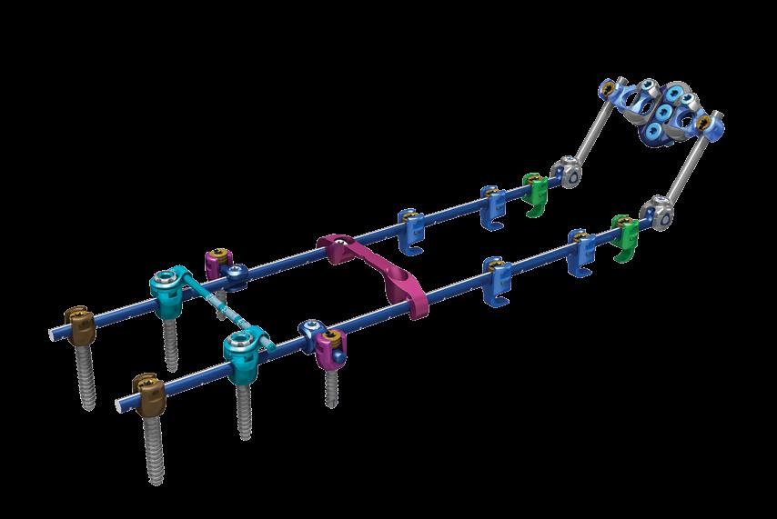
 Extra Rod Connectors/Longitudinal Connectors The Extra Rod Connector connects to Multi Axial Screws and Hooks in the same fashion as the Adjustable Cross Connector caps (Fig. 80).")
 (Fig. 80) Note Extra Rod Connectors can be used transversely or diagonally across the construct to act as a robust Cross Connector.")
31 VUEPOINT II STANDARD TECHNIQUE STEP 15: SUPPLEMENTAL INSTRUMENTATION (CONT.) Extra Rod Connectors/Longitudinal Connectors The Extra Rod Connector connects to Multi Axial Screws and Hooks in the same fashion as the Adjustable Cross Connector caps (Fig. 80). They allow placement of an additional rod medially or laterally (Fig. 81) from the main construct, or across the construct. Final tighten in the same fashion as the Adjustable Cross Connector. (See page 25.) (Fig. 80) Note Extra Rod Connectors can be used transversely or diagonally across the construct to act as a robust Cross Connector. CAUTION Rod-to-Rod Connectors must be used when connecting two separate constructs. Do NOT use VuePoint II Extra Rod Connectors, as the mechanical strength is not adequate for stable fixation of two separate constructs. (Fig. 81) 29
32 VUEPOINT II FROM NUVASIVE VUEPOINT II STANDARD TECHNIQUE REMOVAL If it becomes necessary to remove the VuePoint II construct: 1. Remove Cross Connectors and Extra Rod Connectors if necessary. Fixed Cross Connectors are removed by loosening the Set Screws and taking the Cross Connector out using Holding Forceps. Tulip to Tulip Cross Connectors and Extra Rod Connectors are removed by first loosening the silver lock nuts using the Spoke Driver and then using the Final Tightening Shaft (Black) to unthread the gold Set Screws from within Multi Axial Screws and Laminar Hooks. Set Screws need to be backed all the way out of the tulips and then threaded back in lightly. (Threading the Set Screws back in is important because it ensures that they don t fall out when the Tulip to Tulip Cross Connector Cap is removed.) This causes the Tulip to Tulip Cross Connector Cap to pop up from the tulips and allows them to be removed either by hand or by using the Holding Forceps. 2. Unthread Set Screws from Multi Axial Screws, Laminar Hooks, Keel Plate, or Eyelet Connectors. 3. Remove rods using the Holding Forceps. 4. Use Final Tightening Shaft (Black) to remove Multi Axial Screws and Occipital Bone Screws, as well as Keel Plate or Eyelet Connectors. Laminar Hooks may either be removed using the Holding Forceps or re-engaged with a Threaded Driver. 5. It may be necessary to use the Alignment Tool to reposition Multi Axial Screw tulips for driver re-engagement. If the multi axial motion remains locked after Set Screw removal in Step 2, the Alignment Tool or Counter-Torque may be used to unthread tulip screws. 30
33 VUEPOINT I I OCCIPITAL TECHNIQUE
34 VUEPOINT II FROM NUVASIVE VUEPOINT II OCCIPITAL TECHNIQUE VUEPOINT II OCCIPITAL INSTRUMENTATION OPTIONS The VuePoint II OCT system offers both standard (straight) and angled occipital instrumentation. This array of instrumentation options allows surgeons to more easily address various surgical scenarios. Standard instrumentation should be used in the majority of cases when direct access and trajectories are not overly challenging, and there are not anatomical obstacles that make straight instrumentation problematic. Angled instrumentation should be used when necessary to help navigate cases with difficult occipital angles and challenging thoracic anatomy. Angled instrumentation will help avoid obstructions that may make straight instrumentation strenuous to achieve desired results. Both the Straight and Angled Occipital Drills and Taps should be used through the Drill/Tap Guide to ensure proper depth. The Long Angled Occipital Driver should be used through the Drill/Tap Guide to provide stability. Standard Instrumentation Counter-Torque Screw Driver Shaft Drill Bit Tap Angled Instrumentation Angled Counter-Torque Driver Angled Driver Angled Drill Bit Angled Tap Allen Wrench 32


.")
.")


35 VUEPOINT II OCCIPITAL TECHNIQUE STEP 1: OCCIPITAL KEEL PLATE PLACEMENT Two fixation options are available to address the occiput: 1. The Occipital Keel Plate 2. Eyelet Connectors Occipital Keel Plate The Occipital Keel Plate offers a maximum of five screw placement sites, three in the midline and two lateral. The unique blue/silver bi-colored plate design allows you to visualize proper orientation of the plate: the silver side of the plate should face superior (Fig. 82), which orients the light blue locking Set Screws superiorly. The Keel Plate arms move medial-lateral from 37mm to 47mm and swing cranial-caudal (Figs. 83, 84). After burring down any bony protuberances (while still maintaining the integrity of the cortical bone), if necessary, the plate can be bent to best match the contour of the patient s occiput (Fig. 85). To bend the Keel Plate, it must first be fully compressed to its shortest width and the blue Set Screws finger-tightened. The Keel Plate Bender must then be set to either the concave or convex bend by pulling on the anvil portion and turning it 180. The plate may then be loaded into the bender with blue Set Screws and the silver side of the plate pointing away from the instrument (Figs. 86, 87). (Fig. 82) (Fig. 83) (Fig. 84) CAUTION Care must be exercised not to over bend the Occipital Keel Plate. Do not unbend the plate once the plate is bent, as this may compromise the mechanical strength, and/or cause interference with the Occipital Drill/Tap Guide. (Fig. 85) (Fig. 86) (Fig. 87) 33

.")
36 VUEPOINT II FROM NUVASIVE VUEPOINT II OCCIPITAL TECHNIQUE STEP 1: OCCIPITAL KEEL PLATE PLACEMENT (CONT.) Occipital Keel Plate Fixation Compress the connector arms fully, and lightly finger-tighten the blue Set Screws (Fig. 88). Engage the Occipital Keel Plate with the Keel Plate Holder through the lateral holes of the plate (Fig. 89). (Fig. 88) (Fig. 89) 34
.")
. Attach the Straight Occipital Tap to the Occipital Fat Handle and place through the Drill/Tap Guide. When the depth stop meets the top of the Drill/Tap Guide, stop rotating the tap.")


37 VUEPOINT II OCCIPITAL TECHNIQUE STEP 2: OCCIPITAL SCREW PLACEMENT Select the desired drill depth by pulling the proximal part of the Occipital Drill/Tap Guide backward and toward the handle (Fig. 90). Turn the knurled end of the instrument to the desired depth, noted by the small metal slide which sits in the numbered slot. Insert the Drill/Tap Guide through the aperture of the plate (Fig. 91). Place Drill Bit, attached to power drill, through the Drill/Tap Guide. Drill the three midline holes to desired depth (Fig. 92). (Fig. 90) Occipital Bone Screws require hand-tapping to depth (Fig. 93). Attach the Straight Occipital Tap to the Occipital Fat Handle and place through the Drill/Tap Guide. When the depth stop meets the top of the Drill/Tap Guide, stop rotating the tap. Failure to do so may cause threads to strip. (Fig. 91) CAUTION To prevent stripping of the tap threads, do not attach the tap to power. Always handtap to depth. Note Another option for occipital placement is to place the plate on the occiput and mark the center hole, remove the plate, and drill the hole using the Drill/Tap Guide; then tap the screw hole. After this hole has been created, place the plate back on the occiput and put in your first screw at this site. The benefit of this technique is that it does not require assistance holding the plate holder in place. (Whether you drill through the plate or directly on bone, the depth of the hole in bone will always correspond to the depth setting on the guide. Depth is measured from the bottom of the distal teeth of the guide to the tip of the drill.) (Fig. 92) (Fig. 92a) (Fig. 93a) (Fig. 93) 35
 (Figs. 94, 95). Pick up screw with the Tapered Hex Driver, attached to the Universal Handle. Place the Occipital Bone Screws through the midline holes.")
 CAUTION Lateral screws must be placed through the Occipital Keel Plate prior to opening/ expanding the plate arms.")

38 VUEPOINT II FROM NUVASIVE VUEPOINT II OCCIPITAL TECHNIQUE STEP 2: OCCIPITAL SCREW PLACEMENT (CONT.) Select proper screw length (6-14mm, in 2mm increments) and diameter (blue 4.5mm primary or grey 5.0mm rescue) (Figs. 94, 95). Pick up screw with the Tapered Hex Driver, attached to the Universal Handle. Place the Occipital Bone Screws through the midline holes. Repeat for lateral screw placements while the connector arms are fully compressed. The Occipital Bone Screws can be placed with up to -20 o of angular variability (Fig. 96). (Fig. 94) (Fig. 95) CAUTION Lateral screws must be placed through the Occipital Keel Plate prior to opening/ expanding the plate arms. Once the plate arms are expanded and locked in place, the lateral screw holes are no longer accessible. CAUTION Avoid extreme trajectories for screw placement on the VuePoint II Occipital Keel Plate, specifically where the Drill/Tap Guide is pushed on the plate. This may cause screws to not bottom out and strip the bone; it may also hinder translation of connector arms. (Fig. 97) (Fig. 96) Note Occipital Bone Screws are offered in 4.5mm and 5.0mm diameters, ranging from 6mm to 14mm lengths. The 4.5mm screws are recommended for primary screw placement. The 5.0mm screws should be used only as a rescue screw option. After all desired Bone Screws have been placed, you may loosen the blue Set Screws about a quarter-turn (Fig. 97) to release the mobility of the connector arms and allow for easy connection to the rods (Fig. 98). This step may obscure access to the lateral screws, so they should be fully tightened down to the occiput before adjusting the connector arms to connect the rods. (Fig. 98) 36
 Select the desired drill depth by pulling the proximal part of the Occipital Drill/Tap Guide backward and toward the handle (Fig. 99).")

39 VUEPOINT II OCCIPITAL TECHNIQUE ALTERNATE METHOD ANGLED INSTRUMENTATION OCCIPITAL SCREW PLACEMENT Alternatively, you may use angled instrumentation to complete Step 2. (Fig. 99) Select the desired drill depth by pulling the proximal part of the Occipital Drill/Tap Guide backward and toward the handle (Fig. 99). Turn the knurled end of the instrument to the desired depth, noted by the small metal slide which sits in the numbered slot. Insert the Drill/Tap Guide through the aperture of the plate (Fig. 100). Place Angled Occipital Drill Bit, attached to power drill, through the Drill/Tap Guide. Drill the three midline holes to desired depth (Fig. 101). (Fig. 100) Occipital Bone Screws require hand-tapping to depth (Fig. 102). Attach the Angled Occipital Tap to the Occipital Fat Handle and place through the Drill/Tap Guide. When the depth stop meets the top of the Drill/Tap Guide, stop rotating the Angled Occipital Tap. Failure to do so may cause threads to strip. CAUTION To prevent stripping of the tap threads, do not attach the tap to power. Always handtap to depth. (Fig. 101a) Note Another option for occipital placement is to place the plate on the occiput and mark the center hole, remove the plate, and drill the hole using the Drill/Tap Guide; then tap the screw hole. After this hole has been created, place the plate back on the occiput and put in your first screw at this site. The benefit of this technique is that it does not require assistance holding the plate holder in place. (Whether you drill through the plate or directly on bone, the depth of the hole in bone will always correspond to the depth setting on the guide. Depth is measured from the bottom of the distal teeth of the guide to the tip of the drill.) (Fig. 101) (Fig. 102a) (Fig. 102) 37
 Select proper screw length (6-14mm, in 2mm increments) and diameter (blue 4.5mm primary or grey 5.0mm rescue) (Figs. 103, 104).")
40 VUEPOINT II FROM NUVASIVE VUEPOINT II OCCIPITAL TECHNIQUE ALTERNATE METHOD ANGLED INSTRUMENTATION OCCIPITAL SCREW PLACEMENT (CONT.) Select proper screw length (6-14mm, in 2mm increments) and diameter (blue 4.5mm primary or grey 5.0mm rescue) (Figs. 103, 104). Pick up screw with the Angled Occipital Driver (Long or Short), attached to the Universal Handle. The Long Angled Occipital Driver should be used through the Drill/Tap Guide. Place the Occipital Bone Screws through the midline holes (Fig. 105). Repeat for lateral screw placements while the connector arms are fully compressed. The Occipital Bone Screws can be placed with up to -20 o of angular variability (Fig. 106). (Fig. 103) (Fig. 104) After all desired Bone Screws have been placed, you may loosen the blue Set Screws about a quarter-turn (Reference page 36, Fig. 97) to release the mobility of the connector arms and allow for easy connection to the rods (Reference page 36, Fig. 98). This step may obscure access to the lateral screws, so they should be fully tightened down to the occiput before adjusting the connector arms to connect the rods. CAUTION Lateral screws must be placed through the Occipital Keel Plate prior to opening/ expanding the plate arms. Once the plate arms are expanded and locked in place, the lateral screw holes are no longer accessible. (Fig. 105) CAUTION Avoid extreme trajectories for screw placement on the VuePoint II Occipital Keel Plate, specifically where the Drill/Tap Guide is pushed on the plate. This may cause screws to not bottom out and strip the bone; it may also hinder translation of connector arms. Note Occipital Bone Screws are offered in 4.5mm and 5.0mm diameters, ranging from 6mm to 14mm lengths. The 4.5mm screws are recommended for primary screw placement. The 5.0mm screws should be used only as a rescue screw option. (Fig. 106) 38
. A Counter-Torque is not required.")

. Attach the black-colored Final Tightening Shaft (Black) to the Final Tightening Torque Limiting Handle, and insert through the Counter-Torque to final tighten (Fig.")
41 VUEPOINT II OCCIPITAL TECHNIQUE STEP 3: CONNECTOR ARM TIGHTENING To lock down the arms of the plate, use the Final Tightening Shaft (Black) and Final Tightening Torque Limiting Handle to tighten the light blue Set Screws and lock the plate into desired configuration (Fig. 107). A Counter-Torque is not required. If needed, it is possible to Counter-Torque off of the Keel Plate tulip connectors. Note A Hinged Rod or Precurved Rod can be provisionally tightened down when all Occipital Bone Screws, Multi Axial Screws, and Laminar Hooks are in place. (Fig. 107) STEP 4: LOCKING DOWN THE ROD Once the rod is bent, use the Set Screw Repeater or Tapered Hex Driver to place Set Screws over the rod and tighten them in place (Fig. 108). Attach the black-colored Final Tightening Shaft (Black) to the Final Tightening Torque Limiting Handle, and insert through the Counter-Torque to final tighten (Fig. 109). A tactile and audible click indicates the Set Screw is locked at the recommended 26 in./lb. (3 N-m) of torque. (Fig. 108) (Fig. 109) 39
.")

.")
.")
42 VUEPOINT II FROM NUVASIVE VUEPOINT II OCCIPITAL TECHNIQUE ALTERNATE METHOD ANGLED INSTRUMENTATION LOCKING DOWN THE ROD Once the rod is bent, attach the Angled Occipital Counter-Torque Driver to the Final Tightening Torque Limiting Handle (Fig. 110). Engage a Set Screw with the driver portion of the Angled Occipital Counter- Torque Driver. To do this, push the driver forward and out of the Counter-Torque. Engage the occipital tulip with the Angled Occipital Counter-Torque Driver, and rotate the Final Tightening Torque Limiting Handle to deliver the Set Screw (Fig. 111). Once the Set Screw is fully in place, ensure that the Angled Counter- Torque laser mark on the driver handle is aligned with one of the laser marks on the driver shaft (Fig. 111a). Turn the Final Tightening Torque Limiting Handle until you get a tactile and audible click, confirming it is locked at the recommended 26 in./lb. (3 N-m) of torque. (Fig. 110) Note If the Set Screw is final tightened and laser marks are not in line, release Set Screw from driver shaft and re-engage with the Angled Counter-Torque so the laser marks are in line and repeat Set Screw tightening. (Fig. 111a) 40 (Fig. 111)
. In the unlocked state, the Hinged Rod can be adjusted to the desired angle and then rigidly locked.")
43 VUEPOINT II OCCIPITAL TECHNIQUE STEP 5: HINGED ROD The Hinged Rod may be used in occipital cases for ease of placement and may allow the surgeon to avoid weakening the titanium rod with extreme bends that are often required to fixate the skull in the desired position (Fig. 112). In the unlocked state, the Hinged Rod can be adjusted to the desired angle and then rigidly locked. The Hinged Rod is locked by engaging the Counter-Torque over the hinge and tightening the blue Set Screw to 26 in./lb. (3 N-m), using the Final Tightening Shaft (Black) and Final Tightening Torque Limiting Handle (Fig. 113). (Fig. 112) Note The Hinged Rod Set Screws need to be provisionally tightened before final tightening of the Multi Axial Screws, Laminar Hooks, and Occipital Keel Plate. (Fig. 113) 41
. Eyelet Connectors allow for increased flexibility of Bone Screw placement because they are placed independently of each other (Fig. 115). (Fig. 114) After bending the rod to match the occipital anatomy, preload the Eyelet Connectors to the rod and provisionally tighten.")
44 VUEPOINT II FROM NUVASIVE VUEPOINT II OCCIPITAL TECHNIQUE STEP 6: OCCIPITAL EYELET CONNECTORS Eyelet Connector Fixation Alternatively, Occipital Eyelet Connectors can be utilized for occipital fixation (Fig. 114). Eyelet Connectors allow for increased flexibility of Bone Screw placement because they are placed independently of each other (Fig. 115). (Fig. 114) After bending the rod to match the occipital anatomy, preload the Eyelet Connectors to the rod and provisionally tighten. Connect the desired number of Eyelets for each rod (Fig. 116). Drill, tap, and place Occipital Bone Screws as prescribed earlier in the Occipital Keel Plate step (page 35). Place the Counter-Torque over the Eyelet Connector and use the Final Tightening Shaft (Black) and Final Tightening Torque Limiting Handle assembly to final tighten. (Fig. 115) (Fig. 116) 42
45 VUEPOINT II OCCIPITAL TECHNIQUE REMOVAL If it becomes necessary to remove the VuePoint II construct: 1. Remove Cross Connectors and Extra Rod Connectors if necessary. Fixed Cross Connectors are removed by loosening the Set Screws and taking the Cross Connector out using Holding Forceps. Tulip to Tulip Cross Connectors and Extra Rod Connectors are removed by first loosening the silver lock nuts using the Spoke Driver and then using the Final Tightening Shaft (Black) to unthread the gold Set Screws from within Multi Axial Screws and Laminar Hooks. Set Screws need to be backed all the way out of the tulips and then threaded back in lightly. (Threading the Set Screws back in is important because it ensures that they don t fall out when the Tulip to Tulip Cross Connector Cap is removed.) This causes the Tulip to Tulip Cross Connector Cap to pop up from the tulips and allows them to be removed either by hand or by using the Holding Forceps. 2. Unthread Set Screws from Multi Axial Screws, Laminar Hooks, Occipital Keel Plate, or Eyelet Connectors. 3. Remove rods using the Holding Forceps. 4. Use Final Tightening Shaft (Black) to remove Multi Axial Screws and Occipital Bone Screws, as well as Occipital Keel Plate or Eyelet Connectors. Laminar Hooks may either be removed using the Holding Forceps or re-engaged with a Threaded Driver. 5. It may be necessary to use the Alignment Tool to reposition Multi Axial Screw tulips for driver re-engagement. If the multi axial motion remains locked after Set Screw removal in Step 2, the Alignment Tool or Counter-Torque may be used to unthread tulip screws. 43
46 VUEPOINT II FROM NUVASIVE NOTES
47 PAGE HEADING VUEPOINT II SYSTEM 45
")
 TAP SHAFT, 3.")
 (8977040) 2.")
48 VUEPOINT II FROM NUVASIVE VUEPOINT II SYSTEM VUEPOINT II TRAY 1 (VUE2TRAY1) AWL ( ) BALL TIP PROBE ( ) DEPTH GAUGE ( ) TAP SHAFT, 3.5mm (3.0mm) ( ) TAP SHAFT, 4.0mm (3.5mm) ( ) 2.4mm DRILL BIT ( ) 46
 GEARSHIFT PROBE CURVED (8977170)")
 DRILL GUIDE, 10-40mm")
49 VUEPOINT II SYSTEM GEARSHIFT PROBE STRAIGHT ( ) GEARSHIFT PROBE CURVED ( ) UNIVERSAL HANDLE ( ) OCCIPITAL FAT HANDLE ( ) DRILL GUIDE, 10-40mm ( ) 47
50 VUEPOINT II FROM NUVASIVE VUEPOINT II SYSTEM ADJUSTABLE TAP GUIDE, 10-24mm ( ) VUEPOINT II THREADED DRIVER ( ) SCREW DRIVER SHAFT (STAB-N-GO) ( ) SCREW DRIVER SHAFT (TAPERED DRIVER) ( ) ALIGNMENT TOOL ( ) FINAL TIGHTENING SHAFT (BLACK) ( ) 120mm ROD TEMPLATE ( ) 240mm ROD TEMPLATE ( ) 48
 COUNTER-TORQUE (8977100) FINAL")
 ROD BENDER (8977110) ROD CUTTER")
51 VUEPOINT II SYSTEM SET SCREW REPEATER ( ) COUNTER-TORQUE ( ) FINAL TIGHTENING TORQUE LIMITING HANDLE ( ) ROD BENDER ( ) ROD CUTTER ( ) 49
 IN-SITU ROD BENDER (RIGHT)/TUBE BENDER (BENDING IRON, R) (8977130) IN-SITU ROD BENDER (LEFT)/TUBE BENDER (BENDING IRON, L)")
52 VUEPOINT II FROM NUVASIVE VUEPOINT II SYSTEM VUEPOINT II TRAY 2 (VUE2TRAY2) REDUCTION TOWERS ( ) COMPRESSOR ( ) DISTRACTOR ( ) IN-SITU ROD BENDER (RIGHT)/TUBE BENDER (BENDING IRON, R) ( ) IN-SITU ROD BENDER (LEFT)/TUBE BENDER (BENDING IRON, L) ( ) 50
 ROD HOLDER/HOOK HOLDER/ROD-TO-ROD CONNECTOR HOLDER (HOLDING FORCEPS) (8977115) CROSS CONNECTOR CALIPERS")
53 VUEPOINT II SYSTEM ROCKER (PITCH FORK) ( ) ROD GRIPPER ( ) ROD-TO-ROD DRIVER SHAFT (NV 20) ( ) SPOKE DRIVER ( ) ROD-TO-ROD DRIVER TORQUE LIMITING HANDLE ( ) ROD HOLDER/HOOK HOLDER/ROD-TO-ROD CONNECTOR HOLDER (HOLDING FORCEPS) ( ) CROSS CONNECTOR CALIPERS ( ) 51
 STRAIGHT OCCIPITAL DRILL BIT SHAFT,")
 MIDLINE KEEL PLATE BENDER (8977360) KEEL PLATE HOLDER")
54 VUEPOINT II FROM NUVASIVE VUEPOINT II SYSTEM VUEPOINT II INSTRUMENTS VUEPOINT II OCCIPITAL TRAY (VUE2TRAYOCC) STRAIGHT OCCIPITAL DRILL BIT SHAFT, 3.35mm ( ) STRAIGHT OCCIPITAL TAP, 4.5mm ( ) MIDLINE KEEL PLATE BENDER ( ) KEEL PLATE HOLDER ( ) OCCIPITAL DRILL/TAP GUIDE ( ) 52
 ANGLED OCCIPITAL COUNTER-TORQUE DRIVER (8977370) ANGLED OCCIPITAL")
 ANGLED OCCIPITAL TAP (8977385) ALLEN WRENCH FOR OCCIPITAL")
55 VUEPOINT II SYSTEM VUEPOINT II ANGLED INSTRUMENTS (Not standard in occipital tray; order separately) ANGLED OCCIPITAL COUNTER-TORQUE DRIVER ( ) ANGLED OCCIPITAL DRIVER - LONG ( ) ANGLED OCCIPITAL DRIVER - SHORT ( ) ANGLED OCCIPITAL DRILL BIT ( ) ANGLED OCCIPITAL TAP ( ) ALLEN WRENCH FOR OCCIPITAL ( ) 53
Cervical Solutions. Lineum OCT. Spine System. Surgical Technique Guide
 Cervical Solutions Lineum OCT Spine System Surgical Technique Guide 2 Lineum OCT Spine System Surgical Technique Guide Designed to encourage optimal screw placement and procedural efficiency Lineum OCT
Optima ZS Spinal Fixation System
 Surgical Technique Optima ZS Spinal Fixation System The low-profile, in-line, polyaxial pedicle screw system. Optima ZS Surgical Technique 1 Optima ZS Spinal Fixation System The Optima ZS Spinal Fixation
Surgical Technique ANAX TM OCT. Spinal System
 Surgical Technique ANAX TM OCT Spinal System Product Overview Occipital plate Medial occipital plate (Small, Medium, Large) Lateral occipital plate (Small, Medium, Large) Cortical screw (D4.5mm), Rescue
Anterior Cervical Plate SURGICAL TECHNIQUE GUIDE. Surgeon Driven Innovation
 Anterior Cervical Plate SURGICAL TECHNIQUE GUIDE Surgeon Driven Innovation 1 The Snowmass Anterior Cervical Plate System is intended for the surgical treatment and correction of traumatic and pathologic
BLACKBIRD Spinal System
 BLACKBIRD Spinal System Cervical-Thoracic Spinal Fixation System The ChoiceSpine BLACKBIRD Cervical-Thoracic Spinal Fixation System is a comprehensive system for posterior fixation of the cervical and upper
Technique Guide. Occipito-Cervical Fusion System. Implants and instruments designed to optimize fixation to the occiput.
 Technique Guide Occipito-Cervical Fusion System. Implants and instruments designed to optimize fixation to the occiput. Table of Contents Introduction Overview 2 AO ASIF Principles 4 Indications and Contraindications
Pangea Degenerative Spine System. Top Loading Preassembled Pedicle Screw System for Posterior Stabilization of the Thoracolumbar Spine.
 Technique Guide Pangea Degenerative Spine System. Top Loading Preassembled Pedicle Screw System for Posterior Stabilization of the Thoracolumbar Spine. Contents Introduction AO ASIF Principles 4 Indications
Aesculap Spine S 4 Spinal System. Instrumentation Guide
 Aesculap Spine S 4 Spinal System Instrumentation Guide S 4 Spinal System S 4 From initial conception, the S 4 Spinal System was developed to meet the spine surgeon s need for an extremely low profile and
Virage OCT Spinal Fixation System
 Virage OCT Spinal Fixation System Virage OCT Spinal Fixation System Change Your Perspective Become a Part of the Posterior Fixation Revolution The Virage System is an Occipital-Cervico-Thoracic (OCT) spinal
ACLP Anterior Cervical Locking Plate System TECHNIQUE GUIDE
 ACLP Anterior Cervical Locking Plate System TECHNIQUE GUIDE Instruments and implants approved by the AO Foundation ACLP Anterior Cervical Locking Plate System The ACLP System is designed to reduce the
Reflex TM Surgical Technique. Anterior Cervical Plate
 Reflex TM Surgical Technique Anterior Cervical Plate Surgical Technique Acknowledgement: Stryker Spine extends their thanks to the following surgeons for their participation in the development of the Reflex
Thoracolumbar Solutions. Vitality Spinal Fixation System. Surgical Technique Guide
 Thoracolumbar Solutions Vitality Spinal Fixation System Surgical Technique Guide Vitality Spinal System Surgical Technique Vitality Spinal System Surgical Technique Description, Indications and Contraindications...
Technique Guide. Synapse System. An enhanced set of instruments and implants for posterior stabilization of the cervical and upper thoracic spine.
 Technique Guide Synapse System. An enhanced set of instruments and implants for posterior stabilization of the cervical and upper thoracic spine. Table of Contents Introduction Synapse System 2 AO Principles
Lineum OCT Spine System
 Surgical Technique Lineum OCT Spine System Designed to Encourage Optimal Screw Placement and Procedural Efficiency Game Changing Translation Screw 3.0mm of medial/lateral translation encourages optimal
Ascent. Posterior Occipital Cervico-Thoracic (POCT) System
 System") Ascent Posterior Occipital Cervico-Thoracic (POCT) System Ascent Posterior Occipital Cervico-Thoracic (POCT) System VERSATILITY, RELIABILITY AND SIMPLICITY FOR COMPLEX SPINAL PROCEDURES The Ascent POCT
Ascent Posterior Occipital Cervico-Thoracic (POCT) System Ascent Posterior Occipital Cervico-Thoracic (POCT) System VERSATILITY, RELIABILITY AND SIMPLICITY FOR COMPLEX SPINAL PROCEDURES The Ascent POCT
OPERATIVE TECHNIQUE CENTURION POSTERIOR OCCIPITAL CERVICO-THORACIC (POCT) SYSTEM
 SYSTEM") OPERATIVE TECHNIQUE CENTURION POSTERIOR OCCIPITAL CERVICO-THORACIC (POCT) SYSTEM TABLE OF CONTENTS Introduction 2 System Overview 3 Cervical Operative Technique 4 Thoracic Operative Technique 10 Thoracic
OPERATIVE TECHNIQUE CENTURION POSTERIOR OCCIPITAL CERVICO-THORACIC (POCT) SYSTEM TABLE OF CONTENTS Introduction 2 System Overview 3 Cervical Operative Technique 4 Thoracic Operative Technique 10 Thoracic
Surgical Technique. Deformity - Degenerative. Interbody Fusion. Tumour - Trauma. Cervical. Emerging Technology
 Surgical Technique Deformity - Degenerative Interbody Fusion Tumour - Trauma Cervical Emerging Technology MONARCH SPINE SYSTEM Contents Introduction & Philosophy 2 Surgical Technique Monarch Bolts with
Gibralt. Occipito-Cervico Thoracc System. Operative Technique
 Gibralt Occipito-Cervico Thoracc System Operative Technique TABLE OF CONTENTS GIBRALT...1 OPERATIVE TECHNIQUE OVERVIEW...2 HOOK PLACEMENT...2 SCREW PLACEMENT...2 DETAILED OPERATIVE TECHNIQUE...4 PLACEMENT
URS Degen. Top loading pedicle screw system for posterior stabilization.
 URS Degen. Top loading pedicle screw system for posterior stabilization. Technique Guide This publication is not intended for distribution in the USA. Table of Contents Introduction URS Degen 2 AO Principles
ACCS Anterior Cervical Compression System TECHNIQUE GUIDE
 ACCS Anterior Cervical Compression System TECHNIQUE GUIDE Original Instruments and Implants of the Association for the Study of Internal Fixation AO ASIF ACCS Anterior Cervical Compression System The Anterior
Synapse System. An enhanced set of instruments and implants for posterior stabilization of the upper spine.
 Synapse System. An enhanced set of instruments and implants for posterior stabilization of the upper spine. Technique Guide 100º Instruments and implants approved by the AO Foundation Table of Contents
Thoracolumbar Solutions. Polaris. Deformity System. Trivium. Derotation System. Surgical Technique Guide
 Polaris Deformity System Thoracolumbar Solutions Trivium Derotation System Surgical Technique Guide 2 Polaris Deformity System and Trivium Derotation System Surgical Technique Guide Polaris Deformity System
OCCIPITO-CERVICAL FUSION SYSTEM Implants and instruments designed to optimize fixation to the occiput
 OCCIPITO-CERVICAL FUSION SYSTEM Implants and instruments designed to optimize fixation to the occiput Instruments and implants approved by the AO Foundation. This publication is not intended for distribution
Occipito-Cervical Fusion System
 Implants and Instruments designed to enhance Fixation to the Occiput Occipito-Cervical Fusion System Surgical Technique Image intensifier control This description alone does not provide sufficient background
Occipito-Cervical Fusion System. Implants and instruments designed to optimize fixation to the occiput.
 Occipito-Cervical Fusion System. Implants and instruments designed to optimize fixation to the occiput. Technique Guide This publication is not intended for distribution in the USA. Instruments and implants
Technique Guide. Synapse System. An enhanced set of implants and instruments for posterior stabilization of the cervical and upper thoracic spine.
 Technique Guide Synapse System. An enhanced set of implants and instruments for posterior stabilization of the cervical and upper thoracic spine. Image intensifier control Warning This description alone
OPERATIVE TECHNIQUE COVER IMAGE OPTIONAL (DETAIL) IMAGE FIREBIRD NXG. spinal fixation system
 IMAGE FIREBIRD NXG. spinal fixation system") OPERATIVE TECHNIQUE COVER IMAGE OPTIONAL (DETAIL) IMAGE FIREBIRD NXG spinal fixation system TABLE OF CONTENTS Introduction 1 Operative Technique 2 Reduction Body Technique 18 Implants and Instruments 24
OPERATIVE TECHNIQUE COVER IMAGE OPTIONAL (DETAIL) IMAGE FIREBIRD NXG spinal fixation system TABLE OF CONTENTS Introduction 1 Operative Technique 2 Reduction Body Technique 18 Implants and Instruments 24
VECTRA SURGICAL TECHNIQUE. Anterior cervical plate system. This publication is not intended for distribution in the USA.
 VECTRA Anterior cervical plate system This publication is not intended for distribution in the USA. SURGICAL TECHNIQUE Image intensifier control This description alone does not provide sufficient background
VECTRA. SURGICAL TECHNIQUE. Anterior cervical plate system. This publication is not intended for distribution in the USA.
 VECTRA. Anterior cervical plate system. This publication is not intended for distribution in the USA. SURGICAL TECHNIQUE Contents Indications and contraindications Implants Vario Case Instruments Surgical
REXIOUS SPINAL SYSTEM
 REXIOUS SPINAL SYSTEM SURGICAL TECHNIQUE www.diomedical.com. Site Preparation. Screw Insertion 3. Rod Preparation and Insertion 4. Rod Instruction 5. Set screw Insertion 6. Compression, Distraction & Rotation
VBOSS. Surgical Technique. Vertebral Body Support System
 VBOSS Surgical Technique Vertebral Body Support System 1. System Description 1.1 Implants...3 1.2 Instruments...4 2. Indications...8 3. Patient Position...8 4. Surgical Approach 4.1 Choice of adequate
SYnaPSe oct SYSteM. An enhanced set of instruments and implants for posterior stabilization of the upper spine
 SYnaPSe oct SYSteM An enhanced set of instruments and implants for posterior stabilization of the upper spine SurgIcal technique Table of Contents Introduction SYNAPSE OCT System 2 AO Principles 5 Indications
MaxAn Anterior Cervical Plate System
 Surgical Technique MaxAn Anterior Cervical Plate System Designed to Help Minimize the Potential for Adjacent Level Ossification Allows for screw placement up to 30 cephalad on the superior end of the plate
Lateral Mass Fixation Surgical Technique. and Product Catalog. Distribution For EU Only
 Lateral Mass Fixation Surgical Technique and Product Catalog Distribution For EU Only INTRODUCTION The MOUNTAINEER Occipito-Cervico-Thoracic Spinal System offers a comprehensive solution for rigid posterior
MTP Set SURGICAL TECHNIQUE
 MINI MAXLOCK EXTREME MTP Set SURGICAL TECHNIQUE Contents Table of Contents Key Design Features 3 Surgical Technique Standard MTP Plate 4 MTP Plate with POCKETLOCK Technology 10 Implants and Instruments
A M E D S MART SOLUTIONS FAMILY MEMBER
 A M E D S MART SOLUTIONS FAMILY MEMBER Based in the United Kingdom, Medsmart Solutions is a dynamic 100% British owned company which is dedicated to the manufacture and supply of an extensive range of
VBOSS Surgical Technique
 VBOSS Surgical Technique 1 2 CONTENT 1. System Description 4 1.1 Implants 4 1.2 Instruments 6 2. Indications 11 3. Patient Position 11 4. Surgical Approach 12 4.1 Choice of adequate Parallel Distractor
Aviator Anterior Cervical Plating System System Overview. Visual and tactile confirmation Increased Angulation Simplified instrumentation
 Aviator Anterior Cervical Plating System System Overview Visual and tactile confirmation Increased Angulation Simplified instrumentation The Aviator anterior cervical plating system offers a unique double
Vectra, Vectra-T and Vectra-One. Anterior cervical plating for spinal fusion.
 Vectra, Vectra-T and Vectra-One. Anterior cervical plating for spinal fusion. Technique Guide Instruments and implants approved by the AO Foundation Table of Contents Introduction Vectra, Vectra-T and
D. Greg Anderson, MD Thomas Jefferson University Hospital Philadelphia, PA
 Surgical Technique D E S I G N I N G S U R G E O N S D. Greg Anderson, MD Thomas Jefferson University Hospital Philadelphia, PA Robert Heary, MD University of Medicine and Dentistry of New Jersey Newark,
POLYAXIAL SPINE SYSTEM SURGICAL TECHNIQUE
 POLYAXIAL SPINE SYSTEM SURGICAL TECHNIQUE P O L Y A X I A L S P I N E S Y S T E M POLYAXIALITY STABILITY EFFICIENCY All the implants offer the Polyaxiality, including Hooks, Claws, Sacral Plates and of
Top Loading Pedicle Screw and Hook System for Posterior Stabilization. URS System. Surgical Technique
 Top Loading Pedicle Screw and Hook System for Posterior Stabilization URS System Surgical Technique Image intensifier control This description alone does not provide sufficient background for direct use
TRULY POLYAXIAL, SOLID AND POWERFUL
 S U R G I C A L T E C H N I Q U E V2 TRULY POLYAXIAL, SOLID AND POWERFUL P O L Y A X I A L S P I N E S Y S T E M a decade of results P O L Y A X I A L S P I N E S Y S T E M TRULY POLYAXIAL, SOLID AND POWERFUL
Xia 3 Reference Guide. Version 3-August 2015
 Xia 3 Reference Guide Xia 3 Reference Guide Version 3-August 2015 Table of Contents Implants 03 Blocker 03 Monoaxial Screws 04 Polyaxial Screws 05 Uniplanar Screws 06 Iliac Bolts 07 Rod-to-Rod Connectors
SURGICAL TECHNIQUE. SpineTune THORACO-LUMBAR POSTERIOR OSTEOSYNTHESIS SYSTEM
 SURGICAL TECHNIQUE SpineTune TM TL THORACO-LUMBAR POSTERIOR OSTEOSYNTHESIS SYSTEM SURGICAL TECHNIQUE SpineTune TM TL Table of Contents page Step 1 - Site preparation.......................................................................................
Instructions for Use. LCP Locking Compression Plate. Combine without Compromise.
 Instructions for Use LCP Locking Compression Plate. Combine without Compromise. Table of Contents LCP: Combine without Compromise 2 AO ASIF Principles of Osteosynthesis 4 Indications and Contraindications
Technique Guide. Modular Sternal Cable System. Flexibility and strength in sternal closure and repair.
 Technique Guide Modular Sternal Cable System. Flexibility and strength in sternal closure and repair. Table of Contents Introduction Overview 2 Indications and Contraindications 3 Surgical Technique A.
CSLP Variable Angle. For Use with the Cervical Spine Locking Plate System TECHNIQUE GUIDE. Self-drilling Screw. Variable Screw Angulation
 CSLP Variable Angle For Use with the Cervical Spine Locking Plate System TECHNIQUE GUIDE Self-drilling Screw Variable Screw Angulation Original Instruments and Implants of the Association for the Study
Small Plate and Screw System SURGICAL TECHNIQUE
 MINI MAXLOCK EXTREME Small Plate and Screw System SURGICAL TECHNIQUE Contents Key Design Features 2 Surgical Technique 3 Implants and Instruments 9 Proper surgical procedures and techniques are the responsibility
SYNAPSE SYSTEM An enhanced set of implants and instruments for posterior stabilization of the cervical and upper thoracic spine
 SYNAPSE SYSTEM An enhanced set of implants and instruments for posterior stabilization of the cervical and upper thoracic spine Instruments and implants approved by the AO Foundation. This publication
Back to health. Back to work. Back to life.
 TECHNIQUE Back to health. Back to work. Back to life. U PLUS 90 INSTRUMENTATION OVERVIEW W&H IMPLANTMED POWER UNIT OVERVIEW Low-profile Primary Guides Compresses the U-clip to match rib thickness Clamps
Distal Fibula Plate SURGICAL TECHNIQUE
 MAXLOCK EXTREME Distal Fibula Plate SURGICAL TECHNIQUE Contents Key Design Features 3 Surgical Technique 4 Implants and Instruments 8 Proper surgical procedures and techniques are the responsibility of
ISO Plate SURGICAL TECHNIQUE
 MINI MAXLOCK EXTREME ISO Plate SURGICAL TECHNIQUE Contents Table of Contents Key Design Features 2 Surgical Technique 3 Implants and Instruments 8 Key Design Features The MINI MAXLOCK EXTREME ISO (Intraosseous
TORNIER MAXLOCK EXTREME. Clavicle Plating System SURGICAL TECHNIQUE
 TORNIER MAXLOCK EXTREME Clavicle Plating System SURGICAL TECHNIQUE 2 Table of Contents: Key Design Features...4 Surgical Technique...5 Implants & Instruments...9 3 Key Design Features There are 7 anatomically
6.5 mm and 7.3 mm Cannulated Screws Technique Guide
 6.5 mm and 7.3 mm Cannulated Screws Technique Guide An Integral Part of the SYNTHES Cannulated Screw System Original Instruments and Implants of the Association for the Study of Internal Fixation AO ASIF
Vertebral Body Derotation System Guide and Ordering Information
 Vertebral Body Derotation System Guide and Ordering Information Introduction DePuy Spine continues to support the goal of providing solutions to surgeon challenges when treating spinal disorders. Collaborating
PRODUCT SUMMARY. 80 Total Angulation
 PRODUCT SUMMARY 80 Screw Angulation 40 40 80 Total Angulation 3 Directions of Freedom in Cross Link Low Profile Screws Sizes Available in 3.5mm and 4.0 mm diameters Accomodates 3.5 mm rod Self Drilling,
PAC PLATE A N T E R I O R C E RV I CA L P L AT E SYST E M S U R G I C A L T E C H N I Q U E
 PAC PLATE A N T E R I O R C E RV I CA L P L AT E SYST E M S U R G I C A L T E C H N I Q U E PAC PLATE ANTERIOR CERVICAL PLATE SYSTEM Table of Contents INTRODUCTION System Overview... 1 SURGICAL TECHNIQUE
Interlagos Retractor System Surgical Technique
 Interlagos Retractor System Surgical Technique TABLE OF CONTENTS Instructions for Use Design Rationale Surgical Technique 1. Pre-Operative Preparation 2. Pedicle Preparation 3. Primary Retraction 4. Secondary
S 4. Aesculap. Spinal System. Percutaneous Approach Surgical Technique. Aesculap Spine
 Aesculap Percutaneous Approach Surgical Technique S 4 Spinal System Aesculap Spine S 4 Spinal System Small The S 4 Spinal System features a revolutionary pressure vessel design capable of delivering unmatched
OPERATIVE TECHNIQUE RIVAL REDUCE FRACTURE PLATING SYSTEM. foot & ankle trauma procedures
 OPERATIVE TECHNIQUE RIVAL REDUCE FRACTURE PLATING SYSTEM foot & ankle trauma procedures INTRODUCTION 3 SYSTEM DESCRIPTION 3 TECHNICAL DETAILS 4 SALES AND MARKETING CONFIGURATION 5 OPERATIVE TECHNIQUE 7
Surgical Technique. and Ordering Information
 Surgical Technique and Ordering Information INTRODUCTION CONTENTS The SKYLINE Anterior Cervical Plate provides a versatile system of implants and instruments to accommodate the needs and individual preferences
LCP Pilon Plate 2.7/3.5
 Surgical Technique LCP Locking Compression Plate Original Instruments and Implants of the Association for the Study of Internal Fixation AO/ASIF Table of contents Indications 3 Implants 4 Instruments 5
3.5 mm Cannulated Screw Technique Guide
 3.5 mm Cannulated Screw Technique Guide An Integral Part of the SYNTHES Cannulated Screw System Original Instruments and Implants of the Association for the Study of Internal Fixation AO ASIF The 3.5 mm
Treace Medical Concepts Plating System
 Treace Medical Concepts Plating System Multiplanar Fixation System Surgical Technique Lapidus and 1 st MTP Fusion Lapidus Fusion Surgical Approach 1. Perform a longitudinal incision dorsally over the 1
Table of Contents 2-6. Introduction. Indications Surgical Technique. Ordering Information 15-24
 Table of Contents Introduction Product information ExtremiFix Midsize Large Screw Offering Headless Screw Characteristics Design Features & Benefits Instrumentation Technical Details Calibrated Drill Bits
5th Metatarsal Fracture System Surgical Technique
 5th Metatarsal Fracture System Surgical Technique 5th Metatarsal Fracture System 5th Metatarsal Fracture System The 5th Metatarsal Fracture System (AR-8956S) is a uniquely designed screw and plate system
Surgical Technique 1
 Surgical Technique 1 D-RAD SMART PACK Single-Use Volar Distal Radius Plating System Surgical Technique Table of Contents Indications... 3 Contraindications... 3 D-RAD SMART PACK product overview... 4 Instrumentation...
Universal Humeral Nail
 990210009 INDEX Indications Preoperative Planning Patient Position Surgical Technique - Step 1 Open Humerus - Step 2 Calibrate The Nail - Step 3 Insert Nail - Step 4 Proximal Locking - Step 5 Assemble
ORTHOLINK. 2 - Hole Wedge Osteotomy Plate SURGICAL TECHNIQUE
 MAXLOCK EXTREME ORTHOLINK 2 - Hole Wedge Osteotomy Plate SURGICAL TECHNIQUE Contents Key Design Features 3 Surgical Technique 4 Implants and Instruments 7 Proper surgical procedures and techniques are
QUANTUM SPINAL. Presenter: John Perala, Product Manager. August 14, 2006
 QUANTUM SPINAL ROD SYSTEM Key Features Presenter: John Perala, Product Manager August 14, 2006 Fixed Screw Sizes 475 4.75, 25-40mm 7.75, 30-50mm 5.75, 25-40mm 875 8.75, 30-40mm 6.75, 30-50mm Polyaxial
Technique Guide. 7.0 mm Cannulated Screws. Part of the Synthes Cannulated Screw System.
 Technique Guide 7.0 mm Cannulated Screws. Part of the Synthes Cannulated Screw System. Table of Contents Introduction 7.0 mm Cannulated Screws 2 AO Principles 3 Indications 4 Surgical Technique Surgical
Fibula Plating System
 ANATOMIC LOCKED PLATING SYSTEM Fibula Plating System Securing optimal fixation through versatile locked and compression plating technology Contents Surgeon Design Team 2 Introduction 3 Anatomic Fibula
CD HORIZON REDUCTION MULTI AXIAL SCREW. Spinal System Technical Guide
 CD HORIZON REDUCTION MULTI AXIAL SCREW Spinal System Technical Guide T E C H N I C A L G U I D E CD HORIZON REDUCTION MULTI AXIAL SCREW Spinal System The following describes reduction of a spondylolisthesis
Orthopedic Bone Nail System Universal Humeral Nail
 Orthopedic Bone Nail System Universal Humeral Nail Surgical Technique Manual Note: The surgical procedures should be performed under the guidance of qualified skilled orthopedic surgeons, and this surgical
Integra. Capture Screw System SURGICAL TECHNIQUE
 Integra Capture Screw System SURGICAL TECHNIQUE Table of Contents Indications... 2 Contraindications... 2 System Description... 2 System Features... 2 Cannulated Low-Profile Screws (AC-Series) Overview...
Ankle Fracture System. Surgical Technique STRENGTH FROM WITHIN
 Ankle Fracture System Surgical Technique STRENGTH FROM WITHIN Ankle Fracture System The Sonoma FibuLock nail is the first intramedullary device that has the same indications as plates and delivers anatomic
Reflex Hybrid System Overview
 Spine Reflex Hybrid System Overview Anterior Cervical Plating System Introduction The Reflex Hybrid ACP System offers a low-profile anterior cervical plate along with a selection of bone screw types to
MEDIALMAX System SURGICAL TECHNIQUE
 MAXLOCK EXTREME MEDIALMAX System SURGICAL TECHNIQUE Contents The MEDIALMAX Advantage Design Feature Various flex options POCKETLOCK Technology Anatomic design Advantage Provides the surgeon with multiple
Technique Guide. 4.5 mm Cannulated Screws. Part of the Synthes Cannulated Screw System.
 Technique Guide 4.5 mm Cannulated Screws. Part of the Synthes Cannulated Screw System. TableofContents Introduction 4.5 mm Cannulated Screws 2 AO Principles 3 Indications 4 Surgical Technique Surgical
VLP FOOT Variable Angle Locked Plating System
 Surgical Technique VLP FOOT Variable Angle Locked Plating System Surgical Technique Table of Contents Product overview Implant selection...2 Introduction...3 System overview...4 Indications...4 Design
Technique Guide. LCP Pilon Plate 2.7/3.5
 Technique Guide LCP Pilon Plate 2.7/3.5 LCP Pilon Plate 2.7/3.5 Table of contents Indications 3 Implants 4 Instruments 5 Surgical technique 6 Implant removal 12 Image intensifier control Warning This
Aviator Anterior Cervical Plating System Surgical Technique
 Aviator Anterior Cervical Plating System Surgical Technique Table of Contents System Overview...3-4 Patient Positioning and Exposure...5 Implant Selection and Preparation.... 6-7 Screw Hole Preparation....
OPERATIVE TECHNIQUE RIVAL BITE HEADED CANNULATED AND HEADLESS COMPRESSION SCREWS. foot & ankle applications
 OPERATIVE TECHNIQUE RIVAL BITE HEADED CANNULATED AND HEADLESS COMPRESSION SCREWS foot & ankle applications INTRODUCTION 3 SYSTEM DESCRIPTION 3 TECHNICAL DETAILS 4 SALES AND MARKETING CONFIGURATION 6 OPERATIVE
CETRA ANTERIOR CERVICAL PLATE
 CETRA TM ANTERIOR CERVICAL PLATE The CETRA Anterior Cervical Plate System offers a low profile titanium alloy plate with an intuitive locking mechanism, large graft windows, a high degree of screw angulation
MaxTorque. surgical technique. Cannulated Screw System. Foot & Ankle. OrthoHelix Technology
 MaxTorque Cannulated Screw System OrthoHelix Technology surgical technique Foot & Ankle 2 M A X T O R Q U E C A N N U L A T E D S C R E W S Y S T E M Table of Contents Advantages 3 Indications 4 Contraindications
ACP 1. Anterior Cervical Plating System. Surgical Technique
 ACP 1 Anterior Cervical Plating System Surgical Technique Table of Contents System Overview.... 3 Patient Positioning and Exposure.... 5 Implant Selection and Preparation... 7 Screw Hole Preparation...
7.0 mm Cannulated Screws
 Part of the DePuy Synthes Cannulated Screw System 7.0 mm Cannulated Screws Surgical Technique Table of Contents Introduction 7.0 mm Cannulated Screws 2 AO Principles 3 Indications 4 Surgical Technique
Zimmer Natural Nail System. Cephalomedullary Nail Surgical Technique SMALL
 Zimmer Natural Nail System Cephalomedullary Nail Surgical Technique SMALL Zimmer Natural Nail System Cephalomedullary Nail Technique - Small 1 Zimmer Natural Nail System Cephalomedullary Nail Surgical
ThinLine Anterior Cervical Plate
 ThinLine Anterior Cervical Plate Surgical Technique Solutions by the people of Zimmer Spine. zimmerspine.com Designed for those times when less means more. From the people of Zimmer Spine. ThinLine is
DISTAL RADIUS PLATES 3.5 mm / ANGULARLY STABLE. Distal radius plates 3,5 mm / angularly stable. Locking bone screws. Cortical bone screw
 SURGICAL NÁSTROJE TECHNIQUE PRO ARTROSKOPII DISTAL INSTRUMENTS RADIUS PLATES FOR ARTHROSCOPY 3.5 mm / ANGULARLY STABLE Distal radius plates 3.5 mm / angularly stable Indication The plates are used for
WRIST SYSTEM. ARIX Volar Distal Radius Locking Plate System
 WRIST SYSTEM A Contents 3 4 7 14 15 16 19 21 Indications Product Overview Features & Benefits Ordering Information - Screws -2.5mm Self-Tapping Cortical Screws (Non-Locking) -2.5mm Self-Tapping Locking
Technique Guide Supplement. Standard DHS Lag Screw with LCP DHHS Sideplate.
 Technique Guide Supplement Standard DHS Lag Screw with LCP DHHS Sideplate. Table of Contents Surgical Technique Standard DHS Lag Screw with LCP DHHS 2 Sideplate Technique DHS One-step Lag Screw with DHHS
Humeral Nail System Procedural Steps.
 Humeral Nail System Procedural Steps www.carbo-fix.com Table of Contents Introduction..3 Instrumentation Set... 8 Procedural Steps: Humeral Nail.........10 Procedural Steps: Proximal Humeral Nail.....13
Knee Nail for Retrograde Femoral Mode
 Surgical Technique *smith&nephewt TRIGEN IM Nail System Knee Nail for Retrograde Femoral Mode Table of Contents Indications 2 Surgical Technique 3 TRIGEN STABLE-LOK Nut & Washer Surgical Technique 16 TRIGEN
POLYAXIAL SPINE SYSTEM
 S U R G I C A L T E C H N I Q U E En POLYAXIAL SPINE SYSTEM S C O L I O S I S INSTRUMENTATION A02240010 Pedicle hook starter A02240020 Laminar and transverse process hook starter A02240030 Compressor forceps
UNIQUE PATIENTS SPECIFIC INDICATIONS IN ONE SYSTEM. Surgical Technique
 UNIQUE PATIENTS SPECIFIC INDICATIONS IN ONE SYSTEM Surgical Technique Joint Spine Sports Med Mecta-C Plate Surgical Technique 2 INDEX 1. INTRODUCTION 4 1.1 Mecta-C Cervical Plates 4 1.2 Bone Screws 4 1.3
Global Cup System. Surgical Technique
 Global Cup System Surgical Technique Contents Introduction 2 Pre-operative Planning 3 Suggested Templating Method 3 Surgical Technique 4 Surgical Exposure 4 Acetabular Reaming 4 Acetabular Cup Trialling
Escalate TM. Laminoplasty System Surgical Technique. Expandable Laminoplasty Plate Streamlined Procedure
 Expandable Laminoplasty Plate Streamlined Procedure Table of Contents System Overview.... 3-4 Surgical Procedure....5-12 Expandable Laminoplasty Plate Technique....6-11 Base Laminoplasty Plate Technique....
MTP Fusion Surgical Technique
 MTP Fusion Surgical Technique Patent and Patent Pending CAUTION: Federal Law (USA) restricts this device to sale by or on the order of a physician. INDICATIONS FOR USE The Omni Foot Plating System is intended