Gibralt. Occipito-Cervico Thoracc System. Operative Technique
|
|
|
- Elijah Montgomery
- 6 years ago
- Views:
Transcription
1 Gibralt Occipito-Cervico Thoracc System Operative Technique


2 TABLE OF CONTENTS GIBRALT...1 OPERATIVE TECHNIQUE OVERVIEW...2 HOOK PLACEMENT...2 SCREW PLACEMENT...2 DETAILED OPERATIVE TECHNIQUE...4 PLACEMENT OF LAMINAR HOOKS...4 PLACEMENT OF POLYAXIAL SCREWS...5 SCREW INSERTION...6 ROD PLACEMENT...6 SET SCREW INSERTION...7 COMPRESSION/DISTRACTION...8 FINAL TIGHTENING...8 ADDITIONAL OPTIONS...8 Head to Head Cross Connector Placement...8 Transitional Rods...9 Rod-to-Rod Connectors...9 IMPLANT LISTING...10 INSTRUMENT LISTING...12 INDICATIONS FOR USE...17 GIBRALT OCCIPITAL PLATE...18 OPERATIVE TECHNIQUE OVERVIEW...19 DETAILED OPERATIVE TECHNIQUE...20 SELECTION AND PLACEMENT OF THE OCCIPITAL PLATE...20 CONTOUR THE PLATE...20 DRILL...20 TAP...21 CENTER LINE SCREW INSERTION...21 CUT AND CONTOUR THE ROD...21 ROD INSERTION...22 SET SCREW INSERTION...22 INTIAL TIGHTENING OF THE ARTICULATING ROD...23 FINAL TIGHTENING...23 REMOVAL...23 IMPLANT LISTING...24 INSTRUMENT LISTING...24 INDICATIONS FOR USE...25

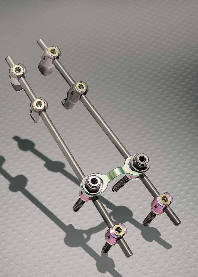
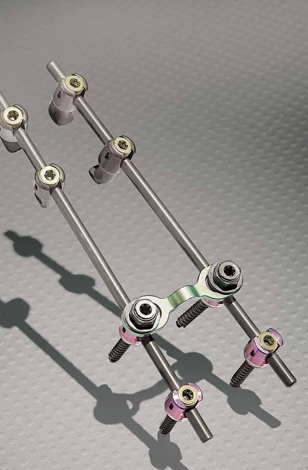
3 GIBRALT The Gibralt Spinal System is a comprehensive solution for posterior stabilization and fusion of the cervical and thoracic spine. Offering exceptional versatility and ease-of-use, the Gibralt Spinal System features top-loading polyaxial screws, hooks, offset connectors and rod-to-rod connectors which can be constructed into a multitude of configurations based on individual patient anatomy. 1


4 OPERATIVE TECHNIQUE OVERVIEW Hook Placement 1 Place Hooks 2 Insert Set Screws Screw Placement 3 Determine Entry Point 4 Cannulate the Pedicle 5 Test Pedicular Wall 6 Drill 7 Tap to Desired Depth 8 Insert Screw 2


5 9 Cut and Contour the Rod 10 Place Rod into Tulip Heads 11 Insert Set Screw 12 Tighten Set Screws 13 Compression/Distraction 14 Final Tightening 15 Additional Options Cross Connectors and Rod-to-Rod Connectors 3

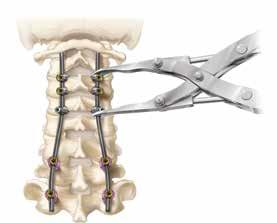
. Figure 1 Clamp Hook The Hooks may be oriented either in a cranial or caudal position.")
6 DETAILED OPERATIVE TECHNIQUE PLACEMENT OF LAMINAR HOOKS Hooks are available for use in the cervical spine. Select the appropriate Hook size and configuration for the anatomy. There are five different types of Hooks available Straight, Left and Right Offset and Left and Right Angle Hooks. Clamp the desired Hook with the Hook Holder making sure that the prongs of the instrument interface with the indentations on the outside head of the Hook (Figure 1). Place Hooks as needed under the superior or inferior lamina (Figure 2). Figure 1 Clamp Hook The Hooks may be oriented either in a cranial or caudal position. Once the Hooks have been inserted, utilize the Set Screw Starter to insert the appropriate inner Set Screw and provisionally tighten in a clockwise motion (Figure 3). Figure 2 Place Hooks Figure 3 Tighten Set Screw 4
. The Probe can then be used to cannulate the pedicle (Figure 5).")
7 Figure 5 Cannulate the Pedicle Figure 4 Determine Entry Point PLACEMENT OF POLYAXIAL SCREWS Determine the ideal entry point for the Polyaxial Screw and penetrate the cortical bone to initiate an entry point using the Awl (Figure 4). The Probe can then be used to cannulate the pedicle (Figure 5). After the pedicle has been cannulated, it may be tested to ensure the integrity of the pedicular wall by using the Sounding Probe (Figure 6). Determine the desired diameter and depth of the drill penetration. There are two drill options available, Fixed and Adjustable. Fixed drills are available in either a 12mm or 14mm depth. Adjustable Drill and Drill Guide Stop offer a drilling depth range from 14mm to 28mm in 2mm increments. The depth is determined by the position of the drill guide stop on the adjustable drill. Figure 6 Test Pedicular Wall Attach the Drill Bit to the desired handle. Align the Drill Guide with the appropriate screw trajectory. Insert the Drill Bit through the Drill Guide and proceed with drilling to the desired depth (Figure 7). Confirm depth and containment within the pilot hole with the Depth Gauge or probe. Figure 7 Drill Tap the pilot hole using the 3.5 or 4.0mm Tap while maintaining the appropriate trajectory (Figure 8). Note: The Taps are undersized by approximately 0.15mm. Continue to drill and tap the remaining pilot holes in the same manner. 5
. Insert the screw into the prepared pilot hole to the desired depth (Figure 10).")


8 SCREW INSERTION Connect the Polyaxial Screwdriver to the desired Handle. After selecting the appropriate screw size, insert the hexalobe tip of the Screwdriver into the screw. Rotate the outer knob of the Screwdriver clockwise until the head of the screw is secured on the Driver (Figure 9). Insert the screw into the prepared pilot hole to the desired depth (Figure 10). To disengage the screw from the driver, turn the knob counterclockwise to and pull straight out of the internal hexalobe on the screw. Figure 8 Tap to Desired Depth The Removal Screwdriver was designed to back out the polyaxial screws if needed. To back out the screw, insert the hexalobe tip of the screwdriver in to the screw. Rotate the outer knob of the screwdriver clockwise until the screwdriver is secured to the screw. Once the screw is engaged, back out the screw by turning the handle counterclockwise. Continue to insert all remaining Polyaxial Screws in the same manner. ROD PLACEMENT The rods are provided in pre-contoured, precut lengths, however a Rod Cutter is provided if other sizes are needed. The final length of the rod should extend 2mm beyond the margin of the screw housing so the screw locking mechanism engages correctly (Figure 11). To contour the rods, secure the rod with the Rod Bender and contour to achieve the desired curvature (Figure 12). Handheld Rod Benders are also available and can be used to provide additional leverage when contouring the rod. Utilize the removal screwdriver to adjust the A-P height of the screws as needed. Adjust the alignment of the Polyaxial Screws using the Head Turner so that the rod openings are in alignment. Once adjusted, they will easily stay in the correct alignment due to the unique EZ Set Tulip Design. Figure 10 Insert Screw Figure 11 Cut the Rod Figure 9 Secure Screw Head on Driver Figure 12 Use Rod Bender to Contour Rods 6

9 Figure 13 Place Rod into Tulip Heads Figure 14 Rod Persuader Place the contoured rod into Polyaxial Screw (Figure 13). If necessary, there are two options for reducing the rod into the Hook or screw heads. 1) The Rod Persuader can be placed over the head of the hook or screw and the handles compressed to reduce the rod (Figure 14). Figure 15 Inline Rod Persuader 2) There are also multiple Inline Rod Persuaders which fit over the individual screw heads. The Inline Rod Persuader Knob is inserted over the top of the Inline Rod Persuader and rotated clockwise to reduce the rod (Figure 15). The Rod Persuader Knob can then be removed and placed over the next Inline Rod Reducer to reduce the rod into the next screw head sequentially. SET SCREW INSERTION Determine the appropriate inner set screw for each Polyaxial Screw or Hook, depending on whether a cross connector will be used at the indicated level. Utilizing the threaded Set Screw Starter, insert the appropriate inner set screw into the Hooks and Polyaxial Screws and provisionally tighten in a clockwise motion (Figure 16). Figure 16 Insert Set Screw 7
.")
. Figure 17 Compressor Distractor Repeat in the same manner on all remaining components to secure the construct.")
10 COMPRESSION/DISTRACTION After the construct has been properly assembled, segmental compression and/or distraction can be accomplished using the Compressor or Distractor while tightening the Set Screws sequentially (Figure 17). FINAL TIGHTENING To perform final tightening of the construct, insert the Set Screw Driver attached to the Torque Limiting Driver through the Counter Torque and turn the Torque Driver clockwise until the Torque Driver audibly clicks (Figure 18). Figure 17 Compressor Distractor Repeat in the same manner on all remaining components to secure the construct. ADDITIONAL OPTIONS Rod to Rod Cross Connector Placement Choose the appropriate size Rod to Rod Cross Connector and contour as needed, using the Cross Connector Benders provided. Capture the Cross Connector Nut with the Cross Connector Nut Starter to hold the cross connector and place onto the rod (Figure 19). Insert the Set Screwdriver attached to the Torque Limiting Driver though the Torque Limiting Nut Driver over the rod to rod cross connector nut into the set screw. Rotate the Torque Limiting Nut Driver counter clockwise until the Torque handle breaks over (Figure 20). Repeat the procedure on the opposite side to final tighten the construct. Figure 18 Final Tightening Figure 19 Place Cross Connector Head to Head Cross Connector Placement Choose the appropriate size Cross Connector and contour as needed, using the Cross Connector Benders provided (Figure 21). Note: It is critical that the Cross Connector be contoured in most situations so that both rings of the cross connector are flush with the base of the tulip. If not contoured correctly, the application of torque to the Cross Connector Nut may cause issues with the inner set screw. Place the Hook Holder around the outside of the Polyaxial Screw where the Cross Connector will be inserted. Capture the retaining nut with the Cross Connector Nut Starter and turn clockwise to thread onto the extended Set Screw (Figure 22). Figure 20 Final Tightening of Cross Connector 8


11 Attach the Torque Limiting Driver to the Nut Driver and rotate clockwise until it audibly clicks to secure the Cross Connecting Retaining Nut (Figure 23). Transitional Rods Transitional Rods and Rod Connectors are available to link to other ChoiceSpine Spinal Systems. The Gibralt System offers two different types of transitional rods, which can be linked to thoracic components. Figure 21 Use Cross Connector Benders to Bend Cross Connector Rod-to-Rod Connectors The Gibralt offers three different sizes of Rod-to-Rod Connectors for use with other ChoiceSpine Spinal Systems. 1) Axial Rod-to-Rod Connectors are available to connect 3.5mm to 5.5.mm and 3.5mm to 6mm rod sizes. 2) Wedding Band Connectors are available to connect 3.5mm to 5.5.mm and 3.5mm to 6mm rod sizes. 3) Inline Rod-to-Rod Connectors are available for 3.5mm to 3.5mm rods. To utilize a Rod-to-Rod connector, select the appropriate type and size and insert the end of the 3.5mm rod into the 3.5mm opening of the connector. Use the Set Screw Starter to engage the appropriate set screw by turning clockwise in the locking hole to secure the rod provisionally. Figure 22 Thread onto Set Screw Note: The open side of the wedding band connector utilizes the Rod to Rod Connector set screw. All other Rod to Rod Connectors utilize the Standard Set Screw. Next, insert the other rod (either 3.5mm, 5.5.mm or 6.0mm depending on the component used) into the remaining opening on the connector. Use the Set Screw Starter to engage the appropriate Set Screw by turning clockwise in the locking hole to secure the rod provisionally (Figure 24). Use the Set Screw Driver connected to the Torque Driver to tighten all Set Screws until the Torque Driver audibly clicks. Figure 23 Secure Cross Connector Figure 24 Wedding Band Rod-to-Rod Connector 9


12 IMPLANT LISTING Catalog Number Part Description Polyaxial Screw 3.5mm x 10mm Polyaxial Screw 3.5mm x 12mm Polyaxial Screw 3.5mm x 14mm Polyaxial Screw 3.5mm x 16mm Polyaxial Screw 3.5mm x 18mm Polyaxial Screw 3.5mm x 20mm Polyaxial Screw 3.5mm x 22mm Polyaxial Screw 3.5mm x 24mm Polyaxial Screw 3.5mm x 26mm Polyaxial Screw 3.5mm x 28mm Polyaxial Screw 3.5mm x 30mm (Optional) Polyaxial Screw 3.5mm x 32mm (Optional) Polyaxial Screw 3.5mm x 34mm (Optional) Polyaxial Screw 3.5mm x 36mm (Optional) Polyaxial Screw 4.0mm x 10mm Polyaxial Screw 4.0mm x 12mm Polyaxial Screw 4.0mm x 14mm Polyaxial Screw 4.0mm x 16mm Polyaxial Screw 4.0mm x 18mm Polyaxial Screw 4.0mm x 20mm Polyaxial Screw 4.0mm x 22mm Polyaxial Screw 4.0mm x 24mm Polyaxial Screw 4.0mm x 26mm Polyaxial Screw 4.0mm x 28mm Polyaxial Screw 4.0mm x 30mm (Optional) Polyaxial Screw 4.0mm x 32mm (Optional) Polyaxial Screw 4.0mm x 34mm (Optional) Polyaxial Screw 4.0mm x 36mm (Optional) Polyaxial Screw 4.5mm x 20mm Polyaxial Screw 4.5mm x 25mm Polyaxial Screw 4.5mm x 30mm Polyaxial Screw 4.5mm x 35mm Polyaxial Screw 4.5mm x 40mm Polyaxial Screw 4.5mm x 45mm Polyaxial Screw 4.5mm x 50mm Polyaxial Smooth Shank Screw 3.5mm x 20mm Polyaxial Smooth Shank Screw 3.5mm x 22mm Polyaxial Smooth Shank Screw 3.5mm x 24mm Polyaxial Smooth Shank Screw 3.5mm x 26mm Polyaxial Smooth Shank Screw 3.5mm x 28mm Polyaxial Smooth Shank Screw 3.5mm x 30mm Polyaxial Smooth Shank Screw 3.5mm x 32mm Polyaxial Smooth Shank Screw 3.5mm x 34mm (Optional) Polyaxial Smooth Shank Screw 3.5mm x 36mm (Optional) Polyaxial Smooth Shank Screw 3.5mm x 38mm (Optional) Polyaxial Smooth Shank Screw 4.0mm x 20mm Polyaxial Smooth Shank Screw 4.0mm x 22mm Polyaxial Smooth Shank Screw 4.0mm x 24mm Polyaxial Smooth Shank Screw 4.0mm x 26mm Polyaxial Smooth Shank Screw 4.0mm x 28mm Polyaxial Smooth Shank Screw 4.0mm x 30mm Polyaxial Smooth Shank Screw 4.0mm x 32mm Polyaxial Smooth Shank Screw 4.0mm x 34mm (Optional) Polyaxial Smooth Shank Screw 4.0mm x 36mm (Optional) Polyaxial Smooth Shank Screw 4.0mm x 38mm (Optional)
13 Catalog Number Part Description Gibralt Curved Rod 30mm Gibralt Curved Rod 40mm Gibralt Curved Rod 50mm Gibralt Curved Rod 60mm Gibralt Curved Rod 70mm Gibralt Curved Rod 80mm Gibralt Curved Rod 90mm Set Screw Cross Connector Set Screw Cross Connector Retaining Nut Rod 3.5mm x 120mm Rod 3.5mm x 240mm Transitional Rod, 3.5mm to 5.5mm x 420mm Transitional Rod, 3.5mm to 6.0mm x 420mm Transitional Rod, 3.5mm to 5.5mm x 600mm Transitional Rod, 3.5mm to 6.0mm x 600mm Cross Connector, 22mm to 28mm Cross Connector, 28mm to 34mm Cross Connector, 34mm to 40mm Cross Connector, 40mm to 46mm Cross Connector, 46mm to 52mm Rod to Rod Cross Connector, 22mm to 30mm Rod to Rod Cross Connector, 26mm to 36mm Rod to Rod Cross Connector, 32mm to 42mm Rod to Rod Cross Connector, 38mm to 48mm Rod to Rod Cross Connector, 44mm to 52mm Set Screw for Rod to Rod Connectors Rod-to-Rod Connector, Inline, 3.5mm to 3.5mm Rod-to-Rod Connector, Combination, 3.5mm to 5.5mm Rod-to-Rod Connector, Combination, 3.5mm to 6.0mm Rod-to-Rod Connector, Wedding Band, 3.5mm to 5.5mm Rod-to-Rod Connector, Wedding Band, 3.5mm to 6.0mm Straight Hook 11
14 IMPLANT LISTING Catalog Number Part Description Left Angle Hook Right Angle Hook Offset Right Hook Offset Left Hook Offset Connector 12mm Lg. Offset Connector 15mm Lg. INSTRUMENT LISTING Catalog Number Part Description Awl Probe Sounding Probe mm Tap 4.0mm Tap Depth Gauge 12
15 Catalog Number Part Description mm Adjustable Drill mm x 12mm fixed drill bit 2.4mm x 14mm fixed drill bit Optional Drill Bits mm x 10mm Fixed Drill Bit 2.0mm x 12mm Fixed Drill Bit 2.0mm x 14mm Fixed Drill Bit 2.0mm x 16mm Fixed Drill Bit 2.4mm x 10mm Fixed Drill Bit 2.4mm x 12mm Fixed Drill Bit 2.4mm x 14mm Fixed Drill Bit 2.4mm x 16mm Fixed Drill Bit 2.7mm x 10mm Fixed Drill Bit 2.7mm x 12mm Fixed Drill Bit 2.7mm x 14mm Fixed Drill Bit 2.7mm x 16mm Fixed Drill Bit 3.0mm x 10mm Fixed Drill Bit 3.0mm x 12mm Fixed Drill Bit 3.0mm x 14mm Fixed Drill Bit 3.0mm x 16mm Fixed Drill Bit Adjustable Drill Stop Drill Guide AO Handle Removal Screwdriver Polyaxial Screwdriver Fixed Handle Polyaxial Screwdriver Gibralt Screwdriver Sleeve Set Screw Starter A/O Connection Double End Set Screw Starter (Optional) Set Screwdriver 13


16 INSTRUMENT LISTING Catalog Number Part Description Counter Torque Counter Torque Cross Connectors Cross Connector Nut Starter Cross Connector Nut Driver Gibralt Cross Connector Torque Handle Rod Bender In-Situ Rod Bender In-Situ Rod Bender Rod Cutter 14


17 Catalog Number Part Description Rod Holder Hook Holder Cross Connector Bender Compressor Distractor Rod Persuader Torque, Short T-Handle Axial Ratchet Handle, Square Drive Ratchet T-Handle, Square Drive 15


18 INSTRUMENT LISTING Catalog Number Part Description Contour Rod Template Polyaxial Screw Driver Polyaxial Head Breaker Polyaxial Screw Countersink Inline Rod Persuader Inline Rod Persuader Knob Gibralt Rod Rocker 16
19 INDICATIONS FOR USE GENERAL DESCRIPTION The Gibralt Spine System is a posterior system intended to help provide immobilization and stabilization of spinal segments as an adjunct to fusion of the cervical, and/ or upper thoracic spine. The system consists of a variety of sizes of rods, hooks, poly-axial screws and connecting components, which can be rigidly locked to the rod in various configurations. The Gibralt Spine System components are manufactured from titanium alloy per ASTM F136. This system can be used independently or in conjunction with ChoiceSpine 5.5mm or 6.0mm rodbased Thoraco-Lumbar Pedicle Screw Systems. The 5.5mm or 6.0mm rod-based Pedicle Screw systems are not covered by these instructions for use. Reference the instructions for use accompanying the Pedicle Screw System components for complete instructions for use. INDICATIONS FOR USE When intended to promote fusion of the cervical spine, and the thoracic spine, (C3-T3), the Gibralt Spine System is indicated for the following: DDD (neck pain of discogenic origin with degeneration of the disc confirmed by history and radiographic studies), spondylolisthesis, spinal stenosis, fracture, dislocation, failed previous fusion and/ or tumors. The hooks and rods are also intended to provide stabilization to promote fusion following reduction of fracture/dislocation or trauma in the cervical/upper thoracic (C3-T3) spine. The use of polyaxial screws is limited to placement in T1-T3 in treating thoracic conditions only. Polyaxial screws are not intended to be placed in the cervical spine. This system can be used independently or in conjunction with ChoiceSpine 5.5mm or 6.0mm rodbased Thoraco-Lumbar Pedicle Screw Systems. CONTRAINDICATIONS FOR USE Contraindications include, but are not limited to: Presence of overt infectious process or significant risk of infection (immunocompromise) Signs of local inflammation Fever or leukocytosis Morbid obesity Pregnancy Mental illness Grossly distorted anatomy caused by congenital abnormalities Any other medical or surgical condition which would preclude the potential benefit of spinal implant surgery, such as the presence of congenital abnormalities, elevation of sedimentation rate unexplained by other diseases, elevation of white blood count, or a marked left shift in the white blood count differential count Suspected or documented metal allergy or intolerance Rapid joint disease, bone absorption, osteopenia, osteomalacia and/or osteoporosis. Osteoporosis or osteopenia is a relative contraindication since this condition may limit the degree of obtainable correction, stabilization, and/or the amount of mechanical fixation Any patient unwilling to follow postoperative instructions Any case not needing a bone graft and fusion Any case where the implant components selected for use would be too large or too small to achieve a successful result Any case that requires the mixing of metals from two different components or systems Any patient having inadequate tissue coverage over the operative site or inadequate bone stock or quality Any patient in which implant utilization would interfere with anatomical structures or expected physiological performance Presence of any neural or vascular deficit or other compromising pathology, which may be further injured by device intervention Any case not described in the indications WARNINGS AND PRECAUTIONS The Gibralt Spine System should only be implanted by experienced spine surgeons with specific training in the use of this spine system because this is a technically demanding procedure presenting a risk of serious injury to the patient. In addition, the surgeon should consider the levels of implantation, patient weight, patient activity level, and other patient conditions (e.g., smoking, occupation), which may impact on the performance of the system. The Gibralt Spine System has not been evaluated for safety and compatibility in the MR environment. The Gibralt Spine System has not been tested for heating or migration in the MR environment. 17
20 GIBRALT OCCIPITAL PLATE The Gibralt Spinal System is a comprehensive solution for posterior stabilization and fusion of the cervical and thoracic spine. Offering exceptional versatility and ease-of-use, the Gibralt Spinal System features top-loading polyaxial screws, hooks, offset connectors and rod-to-rod connectors that can be constructed into a multitude of configurations based on individual patient anatomy. 18


21 OPERATIVE TECHNIQUE OVERVIEW 1 Contouring the Plate 2 Plate Holder Drilling 3 Tapping 4 Screw Insertion 5 Cutting the Rod 6 Contouring the Rod 7 Rod Insertion 8 Tightening of the Articulating Rod 9 Final Tightening 19
. Each Occipital Plate has two sliding connecting points for the rods and 5 holes for fixation (Figure 1).")


22 DETAILED OPERATIVE TECHNIQUE SELECTION AND PLACEMENT OF THE OCCIPITAL PLATE The Gibralt Posterior Cervical Thoracic Spinal Fixation System offers an Occipital Plate for occipital fixation. The Occipital Plate is available in two sizes (Small mm, and large 35-45mm). Each Occipital Plate has two sliding connecting points for the rods and 5 holes for fixation (Figure 1). Figure 1 Occipital Plate Attach the Plate Holder/Drill Guide to the occipital plate and place the plate against the occiput. The Occipital plate should lie smoothly against the bone. It may be necessary to smooth irregular protrubences of the bone slightly while ensuring that significant portions of the cortical bone remain, especially in areas where the screw will be inserted. CONTOUR THE PLATE An Occipital Plate Bender is available to contour the occipital plate for proper seating against the occiput. Slide the Occipital Plate Bender over the plate and apply pressure in the appropriate bend areas to achieve the desired contour with the patient s anatomy. To maintain the integrity of the plate, it should only be bent in one direction (Figure 2). NOTE: Reverse bending of the plates is not recommended. DRILL Using the Plate Holder/Drill Guide with the appropriate Fixed Depth insert, place the occipital plate against the occiput in the desired position (Figure3a). Using the 3.2mm Adjustable Drill, drill the first pilot hole into the most superior fixation hole of the plate. Depth of the pilot hole may be confirmed via use of the Depth Gauge. Figure 2 Contouring the Plate Note: The Plate Holder / Drill Guide Insert must be removed to allow for proper seating of the Depth Gauge, then returned prior to Tapping. The pilot hole is then tapped with a 4.5mm Tap (Figure3b). Figure 3a Plate Holder Figure 3b Plate Holder Drilling 20
.")

23 TAP Due to the thickness of the occipital bone, it is recommended that the bone is fully tapped prior to the insertion of the screw. Place the appropriate size Fixed Depth Insert into the Plate Holder/Drill Guide and insert the 4.5mm Tap through and tap to appropriate depth (Figure 4). Figure 4 Tapping CENTER LINE SCREW INSERTION After both screw holes have been drilled and tapped through the Plate Holder/Drill Guide Insert, remove the Insert and choose the screw that corresponds with the pre drilled depth. The two inferior screws may be inserted through the Plate Holder/Drill Guide, and into the bone using the Occipital Screw Driver. The screws should be inserted fully until they are flush with the plate (Figure 5). It is recommended that a minimum of the three center line screws be utilized for Occipital Plate fixation. Upper plate screws are to be positioned with the aid of the Fixed Depth Drill/Tap Guides. Using the 3.2mm Drill, drill the pilot hole through the Drill/ Tap Guide and the desired fixation hole on the plate (Figure 6a). Depth of the pilot hole may be confirmed by using the Depth Gauge. Figure 6a Drill Figure 5 Screw Insertion Then, insert the 4.5mm Tap through the Fixed Depth Drill/Tap Guide and tap to appropriate depth. Remove the Drill/Tap Guide and choose the screw that corresponds with the pre-drilled depth. Insert the screw through the Occipital Plate, and into the bone using the Occipital Screw Driver. The screw should be inserted fully until it is flush with the plate. If desired, the two remaining screws should be inserted following the technique described above (Figure 6b). CUT AND CONTOUR THE ROD The Rod may be placed with the articulating joint in a cephalad or caudal position based upon the patient anatomy and surgeon preference. Cut and contour the occipital rod so that it lies smoothly against the posterior surface of the occiput and inserts easily into any of the hooks and polyaxial screws. Figure 6b Screw Insertion 21
.")
.")
24 The final length of the rod should extend approximately 2-4mm from the occipital fixation points. If desired, the Contour Rod Template may be used to measure the desired length of the rod. Mark where to cut the rod, insert it into the opening of the Rod Cutter and then squeeze the handles to cut the rod (Figure 7a & b). Figure 7a Cutting the Rod To contour the rod, place the Contour Rod Template along the identified path through the hooks and screws matching the anatomy or desired curve. Use the French Bender to contour the rods by placing the rod in the French Bender and squeezing the handles to achieve the desired curvature (Figure 8). ROD INSERTION Initial Articulating Rod Placement (C3-T3) should be initiated through the Gibralt CT Spinal System Operative Technique. Align Occipital end of the Articulating Rod into the tulip of the Occipital Plate with the Rod Holder Forceps (Figure 9). Figure 7b Cut Rod If additional rod contouring is desired, secure the rod with the In-situ Benders and gently contour until the desired radius is achieved. SET SCREW INSERTION Using the Set Screw Starter, insert the set screw into the tulip of the Occipital Plate and loosely tighten in a clockwise motion. While the rod is held in place, the set screws are provisionally tightened using the Set Screw Driver attached to the desired Handle. Figure 9 Rod Insertion Figure 8 Contouring the Rod 22
.")

25 Figure 10 Initial Tightening of the Articulating Rod Figure 11 Final Tightening of the Rod INTIAL TIGHTENING OF THE ARTICULATING ROD Once the set screws have been placed, perform the initial tightening of the rod joint by using the Articulating Rod Wrench and Articulating Rod Torque Wrench (Figure 10). Hold Articulating Rod Wrench still on the fixed joint and tighten by advancing the loose nut with the Articulating Torque Wrench until the torque wrench audibly breaks over (Figure 11). Repeat on the second rod. FINAL TIGHTENING Prior to Occipital Plate Tightening, ensure that proper anatomical alignment is set. To perform final tightening of the construct, insert the Screw Driver attached to the T-Handle Torque Driver through the Counter Torque and turn the T-Handle Torque Driver clockwise until the Torque Driver audibly clicks. Repeat on the second occipital tulip (Figure 12). Figure 12 Final Tightening REMOVAL To remove the Occitipital Plate, attach the Screw Driver to the desired Handle and turn counter clockwise to remove the set screws. Next, remove the rod by lifting it up out of the construct. To remove the occipital screws, place the Occipital Screw Driver into the head of the screws and turn counter clockwise until screws are removed from the bone. The plate may now be lifted off of the occiput. 23

26 IMPLANT LISTING Catalog Number Part Description Occipital Plate 25mm to 35mm Occipital Plate 35mm to 45mm Gibralt Occipital Screw 4.5x6mm Gibralt Occipital Screw 4.5x8mm Gibralt Occipital Screw 4.5x10mm Gibralt Occipital Screw 4.5x12mm Gibralt Occipital Screw 4.5x14mm Gibralt Occipital Screw 4.5x16mm Gibralt Occipital Screw 5.0 x 6mm Gibralt Occipital Screw 5.0 x 8mm Gibralt Occipital Screw 5.0 x 10mm Gibralt Occipital Screw 5.0 x 12mm Gibralt Occipital Screw 5.0 x 14mm Gibralt Occipital Screw 5.0 x 16mm Articulating Rod-Occipital INSTRUMENT LISTING Catalog Number Part Description mm Flexible Tap mm Tap mm Flexible Drill Bit mm Drill Bit Flexible Screw Driver Occipital Plate Bender Counter Torque Flexible Shaft Occipital Drill Guide Flexible Set Screw Starter Angled Screw Driver Torque Limiting Wrench Articulating Rod 24
27 IMPLANT LISTING Wrench Articulating Rod mm Fixed Insert, Plate Holder/Drill Guide 8mm Fixed Insert, Plate Holder/Drill Guide 10mm Fixed Insert, Plate Holder/Drill Guide 12mm Fixed Insert, Plate Holder/Drill Guide 14mm Fixed Insert, Plate Holder/Drill Guide Fixed Drill Guide, 6mm x 8mm Fixed Drill Guide, 10mm x 12mm Fixed Drill Guide, 14mm x 16mm INDICATIONS FOR USE INDICATIONS FOR USE When used with the Gibralt Spine System, the Gibralt Occipital Spine System is intended to promote fusion of the cervical spine and occipito-cervico-thoracic junction (occiput - T3). The Gibralt Occipital Spine System is indicated for the following: DDD (neck pain of discogenic origin with degeneration of the disc confirmed by history and radiographic studies), spondylolisthesis, spinal stenosis, fracture/dislocation, occipital-cervical dislocation, atlantoaxial fracture with instability, failed previous fusion and/or tumors. The Occipital Bone Screws are limited to occipital fixation only. The use of polyaxial screws is limited to placement in T1-T3 in treating thoracic conditions only. Polyaxial screws are not intended to be placed in the cervical spine. CONTRAINDICATIONS FOR USE Contraindications include, but are not limited to: Presence of overt infectious process or significant risk of infection (Immunocompromise) Signs of local inflammation Fever of leukocytosis Morbid obesity Pregnancy Mental Illness Severe comminuted fractures, such that segments may not be maintained in satisfactory proximate reduction Grossly distorted anatomy caused by congenital abnormalities Any other medical or surgical condition which would preclude the potential benefit of spinal implant surgery, such as the presence of congenital abnormalities, elevation of sedimentation rate unexplained by other diseases, elevation of white blood count, or a marked left shift in the white blood count differential count Suspected or documented metal allergy or intolerance Rapid joint disease, bone absorption, osteopenia, osteomalacia and/or osteoporosis. Osteoporosis or osteopenia is a relative contraindication since this condition may limit the degree of obtainable correction, stabilization, and/or the amount of mechanical fixation Any patient unwilling to follow postoperative instructions Any case not needing a bone graft and fusion Any case that requires the implant components selected for use would be too large or too small to achieve a successful result Any case that requires the mixing of metals from two different components or systems Any patient having inadequate tissue coverage over the operative site or inadequate bone stock or quality Any patient in which implant utilization would interfere with anatomical structures or expected physiological performance Presence of any neural or vascular deficient or other compromising pathology, which may be further injured by device intervention Any case not described in the indications WARNINGS AND PRECAUTIONS The Gibralt Occipital Spine System should only be implanted by experienced spine surgeons with specific training in the use of this spine system because this is a technically demanding procedure presenting a risk of serious injury to the patient. In addition, the surgeon should consider the levels of implantation, patient weight, patient activity level, and other patient conditions (e.g., smoking, occupation), which may impact on the performance of the system. The Gibralt Occipital Spine System has not been tested for safety and compatibility in the MR environment. The Gibralt Occipital Spine System has not been tested for heating or migration in the MR environment. 25
28 ChoiceSpine, Inc. is proud to have offices and distributors around the globe. For more information about ChoiceSpine products available in your country, please visit For additional device information, refer to the ChoiceSpine-Instructions for Use for a device description, indications, contraindications, precautions and warnings. For further product information, please contact Customer Service, ChoiceSpine, 400 Erin Drive Knoxville, TN (865) , FAX (865) This Gibralt Operative Technique has been developed in cooperation with Ronald Moskovich, MD and Erich Richter, MD. ChoiceSpine, Inc. as the manufacturer of this device, does not practice medicine, and is not responsible for recommending the appropriate surgical technique for use on a particular patient. These guidelines are intended to be solely informational and each surgeon must evaluate the appropriateness of these guidelines based on his or her personal medical training and experience. Prior to use of this system, the surgeon should refer to the product package insert for comprehensive warnings, precautions, indications for use, contraindications and adverse effects. The products discussed herein may be available under different trademarks in different countries. All copyrights, and pending and registered trademarks, are property of ChoiceSpine, Inc. This material is intended for the sole use and benefit of the ChoiceSpine sales force and physicians. It should not be redistributed, duplicated or disclosed without the express written consent of ChoiceSpine, Inc ChoiceSpine, Inc LIT # Gibralt STG Rev 01 6/17
BLACKBIRD Spinal System
 BLACKBIRD Spinal System Cervical-Thoracic Spinal Fixation System The ChoiceSpine BLACKBIRD Cervical-Thoracic Spinal Fixation System is a comprehensive system for posterior fixation of the cervical and upper
Optima ZS Spinal Fixation System
 Surgical Technique Optima ZS Spinal Fixation System The low-profile, in-line, polyaxial pedicle screw system. Optima ZS Surgical Technique 1 Optima ZS Spinal Fixation System The Optima ZS Spinal Fixation
Technique Guide. Occipito-Cervical Fusion System. Implants and instruments designed to optimize fixation to the occiput.
 Technique Guide Occipito-Cervical Fusion System. Implants and instruments designed to optimize fixation to the occiput. Table of Contents Introduction Overview 2 AO ASIF Principles 4 Indications and Contraindications
Surgical Technique ANAX TM OCT. Spinal System
 Surgical Technique ANAX TM OCT Spinal System Product Overview Occipital plate Medial occipital plate (Small, Medium, Large) Lateral occipital plate (Small, Medium, Large) Cortical screw (D4.5mm), Rescue
Cervical Solutions. Lineum OCT. Spine System. Surgical Technique Guide
 Cervical Solutions Lineum OCT Spine System Surgical Technique Guide 2 Lineum OCT Spine System Surgical Technique Guide Designed to encourage optimal screw placement and procedural efficiency Lineum OCT
Technique Guide. Synapse System. An enhanced set of instruments and implants for posterior stabilization of the cervical and upper thoracic spine.
 Technique Guide Synapse System. An enhanced set of instruments and implants for posterior stabilization of the cervical and upper thoracic spine. Table of Contents Introduction Synapse System 2 AO Principles
Synapse System. An enhanced set of instruments and implants for posterior stabilization of the upper spine.
 Synapse System. An enhanced set of instruments and implants for posterior stabilization of the upper spine. Technique Guide 100º Instruments and implants approved by the AO Foundation Table of Contents
Thoracolumbar Solutions. Vitality Spinal Fixation System. Surgical Technique Guide
 Thoracolumbar Solutions Vitality Spinal Fixation System Surgical Technique Guide Vitality Spinal System Surgical Technique Vitality Spinal System Surgical Technique Description, Indications and Contraindications...
URS Degen. Top loading pedicle screw system for posterior stabilization.
 URS Degen. Top loading pedicle screw system for posterior stabilization. Technique Guide This publication is not intended for distribution in the USA. Table of Contents Introduction URS Degen 2 AO Principles
SYnaPSe oct SYSteM. An enhanced set of instruments and implants for posterior stabilization of the upper spine
 SYnaPSe oct SYSteM An enhanced set of instruments and implants for posterior stabilization of the upper spine SurgIcal technique Table of Contents Introduction SYNAPSE OCT System 2 AO Principles 5 Indications
Surgical Technique. Deformity - Degenerative. Interbody Fusion. Tumour - Trauma. Cervical. Emerging Technology
 Surgical Technique Deformity - Degenerative Interbody Fusion Tumour - Trauma Cervical Emerging Technology MONARCH SPINE SYSTEM Contents Introduction & Philosophy 2 Surgical Technique Monarch Bolts with
Ascent. Posterior Occipital Cervico-Thoracic (POCT) System
 System") Ascent Posterior Occipital Cervico-Thoracic (POCT) System Ascent Posterior Occipital Cervico-Thoracic (POCT) System VERSATILITY, RELIABILITY AND SIMPLICITY FOR COMPLEX SPINAL PROCEDURES The Ascent POCT
Ascent Posterior Occipital Cervico-Thoracic (POCT) System Ascent Posterior Occipital Cervico-Thoracic (POCT) System VERSATILITY, RELIABILITY AND SIMPLICITY FOR COMPLEX SPINAL PROCEDURES The Ascent POCT
ACLP Anterior Cervical Locking Plate System TECHNIQUE GUIDE
 ACLP Anterior Cervical Locking Plate System TECHNIQUE GUIDE Instruments and implants approved by the AO Foundation ACLP Anterior Cervical Locking Plate System The ACLP System is designed to reduce the
Occipito-Cervical Fusion System. Implants and instruments designed to optimize fixation to the occiput.
 Occipito-Cervical Fusion System. Implants and instruments designed to optimize fixation to the occiput. Technique Guide This publication is not intended for distribution in the USA. Instruments and implants
Lineum OCT Spine System
 Surgical Technique Lineum OCT Spine System Designed to Encourage Optimal Screw Placement and Procedural Efficiency Game Changing Translation Screw 3.0mm of medial/lateral translation encourages optimal
OPERATIVE TECHNIQUE CENTURION POSTERIOR OCCIPITAL CERVICO-THORACIC (POCT) SYSTEM
 SYSTEM") OPERATIVE TECHNIQUE CENTURION POSTERIOR OCCIPITAL CERVICO-THORACIC (POCT) SYSTEM TABLE OF CONTENTS Introduction 2 System Overview 3 Cervical Operative Technique 4 Thoracic Operative Technique 10 Thoracic
OPERATIVE TECHNIQUE CENTURION POSTERIOR OCCIPITAL CERVICO-THORACIC (POCT) SYSTEM TABLE OF CONTENTS Introduction 2 System Overview 3 Cervical Operative Technique 4 Thoracic Operative Technique 10 Thoracic
ThinLine Anterior Cervical Plate
 ThinLine Anterior Cervical Plate Surgical Technique Solutions by the people of Zimmer Spine. zimmerspine.com Designed for those times when less means more. From the people of Zimmer Spine. ThinLine is
OCCIPITO-CERVICAL FUSION SYSTEM Implants and instruments designed to optimize fixation to the occiput
 OCCIPITO-CERVICAL FUSION SYSTEM Implants and instruments designed to optimize fixation to the occiput Instruments and implants approved by the AO Foundation. This publication is not intended for distribution
Technique Guide. Synapse System. An enhanced set of implants and instruments for posterior stabilization of the cervical and upper thoracic spine.
 Technique Guide Synapse System. An enhanced set of implants and instruments for posterior stabilization of the cervical and upper thoracic spine. Image intensifier control Warning This description alone
VECTRA. SURGICAL TECHNIQUE. Anterior cervical plate system. This publication is not intended for distribution in the USA.
 VECTRA. Anterior cervical plate system. This publication is not intended for distribution in the USA. SURGICAL TECHNIQUE Contents Indications and contraindications Implants Vario Case Instruments Surgical
VECTRA SURGICAL TECHNIQUE. Anterior cervical plate system. This publication is not intended for distribution in the USA.
 VECTRA Anterior cervical plate system This publication is not intended for distribution in the USA. SURGICAL TECHNIQUE Image intensifier control This description alone does not provide sufficient background
Vectra, Vectra-T and Vectra-One. Anterior cervical plating for spinal fusion.
 Vectra, Vectra-T and Vectra-One. Anterior cervical plating for spinal fusion. Technique Guide Instruments and implants approved by the AO Foundation Table of Contents Introduction Vectra, Vectra-T and
A M E D S MART SOLUTIONS FAMILY MEMBER
 A M E D S MART SOLUTIONS FAMILY MEMBER Based in the United Kingdom, Medsmart Solutions is a dynamic 100% British owned company which is dedicated to the manufacture and supply of an extensive range of
Reflex TM Surgical Technique. Anterior Cervical Plate
 Reflex TM Surgical Technique Anterior Cervical Plate Surgical Technique Acknowledgement: Stryker Spine extends their thanks to the following surgeons for their participation in the development of the Reflex
Occipito-Cervical Fusion System
 Implants and Instruments designed to enhance Fixation to the Occiput Occipito-Cervical Fusion System Surgical Technique Image intensifier control This description alone does not provide sufficient background
Pangea Degenerative Spine System. Top Loading Preassembled Pedicle Screw System for Posterior Stabilization of the Thoracolumbar Spine.
 Technique Guide Pangea Degenerative Spine System. Top Loading Preassembled Pedicle Screw System for Posterior Stabilization of the Thoracolumbar Spine. Contents Introduction AO ASIF Principles 4 Indications
Lateral Mass Fixation Surgical Technique. and Product Catalog. Distribution For EU Only
 Lateral Mass Fixation Surgical Technique and Product Catalog Distribution For EU Only INTRODUCTION The MOUNTAINEER Occipito-Cervico-Thoracic Spinal System offers a comprehensive solution for rigid posterior
Escalate TM. Laminoplasty System Surgical Technique. Expandable Laminoplasty Plate Streamlined Procedure
 Expandable Laminoplasty Plate Streamlined Procedure Table of Contents System Overview.... 3-4 Surgical Procedure....5-12 Expandable Laminoplasty Plate Technique....6-11 Base Laminoplasty Plate Technique....
UNIQUE PATIENTS SPECIFIC INDICATIONS IN ONE SYSTEM. Surgical Technique
 UNIQUE PATIENTS SPECIFIC INDICATIONS IN ONE SYSTEM Surgical Technique Joint Spine Sports Med Mecta-C Plate Surgical Technique 2 INDEX 1. INTRODUCTION 4 1.1 Mecta-C Cervical Plates 4 1.2 Bone Screws 4 1.3
UNIQUE PATIENTS SPECIFIC INDICATIONS IN ONE SYSTEM. Surgical Technique
 UNIQUE PATIENTS SPECIFIC INDICATIONS IN ONE SYSTEM Surgical Technique Joint Spine Sports Med Mecta-C Plate Surgical Technique 2 INDEX 1. INTRODUCTION 4 1.1 Mecta-C Cervical Plates 4 1.2 Bone Screws 4 1.3
SURGICAL TECHNIQUE. SpineTune THORACO-LUMBAR POSTERIOR OSTEOSYNTHESIS SYSTEM
 SURGICAL TECHNIQUE SpineTune TM TL THORACO-LUMBAR POSTERIOR OSTEOSYNTHESIS SYSTEM SURGICAL TECHNIQUE SpineTune TM TL Table of Contents page Step 1 - Site preparation.......................................................................................
SYNAPSE SYSTEM An enhanced set of implants and instruments for posterior stabilization of the cervical and upper thoracic spine
 SYNAPSE SYSTEM An enhanced set of implants and instruments for posterior stabilization of the cervical and upper thoracic spine Instruments and implants approved by the AO Foundation. This publication
Anterior Cervical Plate SURGICAL TECHNIQUE GUIDE. Surgeon Driven Innovation
 Anterior Cervical Plate SURGICAL TECHNIQUE GUIDE Surgeon Driven Innovation 1 The Snowmass Anterior Cervical Plate System is intended for the surgical treatment and correction of traumatic and pathologic
ACCS Anterior Cervical Compression System TECHNIQUE GUIDE
 ACCS Anterior Cervical Compression System TECHNIQUE GUIDE Original Instruments and Implants of the Association for the Study of Internal Fixation AO ASIF ACCS Anterior Cervical Compression System The Anterior
Aesculap Spine S 4 Spinal System. Instrumentation Guide
 Aesculap Spine S 4 Spinal System Instrumentation Guide S 4 Spinal System S 4 From initial conception, the S 4 Spinal System was developed to meet the spine surgeon s need for an extremely low profile and
Vertebral Body Derotation System Guide and Ordering Information
 Vertebral Body Derotation System Guide and Ordering Information Introduction DePuy Spine continues to support the goal of providing solutions to surgeon challenges when treating spinal disorders. Collaborating
SlimLine Anterior Cervical Plate
 SlimLine Anterior Cervical Plate Surgical Technique Solutions by the people of Zimmer Spine. zimmerspine.com Efficient Design. Proven Results. From the people of Zimmer Spine. SlimLine is backed by an
ThinLine. Surgical Technique. Anterior Cervical Plate. zimmerspine.com
 ThinLine Anterior Cervical Plate Surgical Technique zimmerspine.com Designed for those times when less means more. From the people of Zimmer Spine. The ThinLine System is the lowest profile plate in the
MaxAn Anterior Cervical Plate System
 Surgical Technique MaxAn Anterior Cervical Plate System Designed to Help Minimize the Potential for Adjacent Level Ossification Allows for screw placement up to 30 cephalad on the superior end of the plate
ACP 1. Anterior Cervical Plating System. Surgical Technique
 ACP 1 Anterior Cervical Plating System Surgical Technique Table of Contents System Overview.... 3 Patient Positioning and Exposure.... 5 Implant Selection and Preparation... 7 Screw Hole Preparation...
OPERATIVE TECHNIQUE COVER IMAGE OPTIONAL (DETAIL) IMAGE FIREBIRD NXG. spinal fixation system
 IMAGE FIREBIRD NXG. spinal fixation system") OPERATIVE TECHNIQUE COVER IMAGE OPTIONAL (DETAIL) IMAGE FIREBIRD NXG spinal fixation system TABLE OF CONTENTS Introduction 1 Operative Technique 2 Reduction Body Technique 18 Implants and Instruments 24
OPERATIVE TECHNIQUE COVER IMAGE OPTIONAL (DETAIL) IMAGE FIREBIRD NXG spinal fixation system TABLE OF CONTENTS Introduction 1 Operative Technique 2 Reduction Body Technique 18 Implants and Instruments 24
Integra. Capture Screw System SURGICAL TECHNIQUE
 Integra Capture Screw System SURGICAL TECHNIQUE Table of Contents Indications... 2 Contraindications... 2 System Description... 2 System Features... 2 Cannulated Low-Profile Screws (AC-Series) Overview...
D. Greg Anderson, MD Thomas Jefferson University Hospital Philadelphia, PA
 Surgical Technique D E S I G N I N G S U R G E O N S D. Greg Anderson, MD Thomas Jefferson University Hospital Philadelphia, PA Robert Heary, MD University of Medicine and Dentistry of New Jersey Newark,
Xia 3 Reference Guide. Version 3-August 2015
 Xia 3 Reference Guide Xia 3 Reference Guide Version 3-August 2015 Table of Contents Implants 03 Blocker 03 Monoaxial Screws 04 Polyaxial Screws 05 Uniplanar Screws 06 Iliac Bolts 07 Rod-to-Rod Connectors
REXIOUS SPINAL SYSTEM
 REXIOUS SPINAL SYSTEM SURGICAL TECHNIQUE www.diomedical.com. Site Preparation. Screw Insertion 3. Rod Preparation and Insertion 4. Rod Instruction 5. Set screw Insertion 6. Compression, Distraction & Rotation
Nakoma-SL Anterior Cervical Plating System Surgical Technique
 Anterior Cervical Plating System Surgical Technique Table of Contents Indications for Use................................1 Device Description............................... 1 Nakoma-SL Implant Key Features.........................2
Top Loading Pedicle Screw and Hook System for Posterior Stabilization. URS System. Surgical Technique
 Top Loading Pedicle Screw and Hook System for Posterior Stabilization URS System Surgical Technique Image intensifier control This description alone does not provide sufficient background for direct use
Aviator Anterior Cervical Plating System Surgical Technique
 Aviator Anterior Cervical Plating System Surgical Technique Table of Contents System Overview...3-4 Patient Positioning and Exposure...5 Implant Selection and Preparation.... 6-7 Screw Hole Preparation....
POLYAXIAL SPINE SYSTEM SURGICAL TECHNIQUE
 POLYAXIAL SPINE SYSTEM SURGICAL TECHNIQUE P O L Y A X I A L S P I N E S Y S T E M POLYAXIALITY STABILITY EFFICIENCY All the implants offer the Polyaxiality, including Hooks, Claws, Sacral Plates and of
Virage OCT Spinal Fixation System
 Virage OCT Spinal Fixation System Virage OCT Spinal Fixation System Change Your Perspective Become a Part of the Posterior Fixation Revolution The Virage System is an Occipital-Cervico-Thoracic (OCT) spinal
CSLP Variable Angle. For Use with the Cervical Spine Locking Plate System TECHNIQUE GUIDE. Self-drilling Screw. Variable Screw Angulation
 CSLP Variable Angle For Use with the Cervical Spine Locking Plate System TECHNIQUE GUIDE Self-drilling Screw Variable Screw Angulation Original Instruments and Implants of the Association for the Study
PRODUCT SUMMARY. 80 Total Angulation
 PRODUCT SUMMARY 80 Screw Angulation 40 40 80 Total Angulation 3 Directions of Freedom in Cross Link Low Profile Screws Sizes Available in 3.5mm and 4.0 mm diameters Accomodates 3.5 mm rod Self Drilling,
OPERATIVE TECHNIQUE RIVAL REDUCE FRACTURE PLATING SYSTEM. foot & ankle trauma procedures
 OPERATIVE TECHNIQUE RIVAL REDUCE FRACTURE PLATING SYSTEM foot & ankle trauma procedures INTRODUCTION 3 SYSTEM DESCRIPTION 3 TECHNICAL DETAILS 4 SALES AND MARKETING CONFIGURATION 5 OPERATIVE TECHNIQUE 7
PAC PLATE A N T E R I O R C E RV I CA L P L AT E SYST E M S U R G I C A L T E C H N I Q U E
 PAC PLATE A N T E R I O R C E RV I CA L P L AT E SYST E M S U R G I C A L T E C H N I Q U E PAC PLATE ANTERIOR CERVICAL PLATE SYSTEM Table of Contents INTRODUCTION System Overview... 1 SURGICAL TECHNIQUE
Small Plate and Screw System SURGICAL TECHNIQUE
 MINI MAXLOCK EXTREME Small Plate and Screw System SURGICAL TECHNIQUE Contents Key Design Features 2 Surgical Technique 3 Implants and Instruments 9 Proper surgical procedures and techniques are the responsibility
TRULY POLYAXIAL, SOLID AND POWERFUL
 S U R G I C A L T E C H N I Q U E V2 TRULY POLYAXIAL, SOLID AND POWERFUL P O L Y A X I A L S P I N E S Y S T E M a decade of results P O L Y A X I A L S P I N E S Y S T E M TRULY POLYAXIAL, SOLID AND POWERFUL
Technique Guide. 7.0 mm Cannulated Screws. Part of the Synthes Cannulated Screw System.
 Technique Guide 7.0 mm Cannulated Screws. Part of the Synthes Cannulated Screw System. Table of Contents Introduction 7.0 mm Cannulated Screws 2 AO Principles 3 Indications 4 Surgical Technique Surgical
VariAx DistalFibula. Foot & Ankle. Locking Plate System. Operative Technique
 VariAx DistalFibula Locking Plate System Operative Technique Foot & Ankle Distal Fibula Fracture Repair Polyaxial Locking Technology Low Profile Design VariAx 2 Color Coded Screws and Instruments VariAx
Technique Guide. Modular Sternal Cable System. Flexibility and strength in sternal closure and repair.
 Technique Guide Modular Sternal Cable System. Flexibility and strength in sternal closure and repair. Table of Contents Introduction Overview 2 Indications and Contraindications 3 Surgical Technique A.
Interlagos Retractor System Surgical Technique
 Interlagos Retractor System Surgical Technique TABLE OF CONTENTS Instructions for Use Design Rationale Surgical Technique 1. Pre-Operative Preparation 2. Pedicle Preparation 3. Primary Retraction 4. Secondary
MTP Set SURGICAL TECHNIQUE
 MINI MAXLOCK EXTREME MTP Set SURGICAL TECHNIQUE Contents Table of Contents Key Design Features 3 Surgical Technique Standard MTP Plate 4 MTP Plate with POCKETLOCK Technology 10 Implants and Instruments
Thoracolumbar Solutions. Polaris. Deformity System. Trivium. Derotation System. Surgical Technique Guide
 Polaris Deformity System Thoracolumbar Solutions Trivium Derotation System Surgical Technique Guide 2 Polaris Deformity System and Trivium Derotation System Surgical Technique Guide Polaris Deformity System
V2F Anterior Fixation System
 TM V2F Anterior Fixation System Surgical Technique Solutions by the people of Zimmer Spine. zimmerspine.com Traditional approach. New Technique. From the people of Zimmer Spine. The V2F Anterior Fixation
3.5 mm Cannulated Screw Technique Guide
 3.5 mm Cannulated Screw Technique Guide An Integral Part of the SYNTHES Cannulated Screw System Original Instruments and Implants of the Association for the Study of Internal Fixation AO ASIF The 3.5 mm
MaxTorque. surgical technique. Cannulated Screw System. Foot & Ankle. OrthoHelix Technology
 MaxTorque Cannulated Screw System OrthoHelix Technology surgical technique Foot & Ankle 2 M A X T O R Q U E C A N N U L A T E D S C R E W S Y S T E M Table of Contents Advantages 3 Indications 4 Contraindications
The Percutaneous Reduction Forceps Technique Guide
 The Percutaneous Reduction Forceps Technique Guide Indications + Product Overview Introduction The Percutaneous Reduction Forceps The Percutaneous Reduction Forceps facilitate standard technique for fixation
DART-FIRE. Small Screw System SURGICAL TECHNIQUE
 DART-FIRE Small Screw System SURGICAL TECHNIQUE DART-FIRE Small Screw System SURGICAL TECHNIQUE Contents Chapter 1 4 Chapter 2 6 Appendix 1 9 Appendix 2 11 Introduction DART-FIRE Small Screw System Surgical
DART-FIRE. Small Screw System SURGICAL TECHNIQUE
 DART-FIRE Small Screw System SURGICAL TECHNIQUE DART-FIRE Small Screw System Surgical Technique Contents Chapter 1 4 Chapter 2 6 Chapter 3 7 Appendix 1 10 Appendix 2 12 Introduction Intended Use DART-FIRE
Table of Contents 2-6. Introduction. Indications Surgical Technique. Ordering Information 15-24
 Table of Contents Introduction Product information ExtremiFix Midsize Large Screw Offering Headless Screw Characteristics Design Features & Benefits Instrumentation Technical Details Calibrated Drill Bits
Technique Guide. 4.5 mm Cannulated Screws. Part of the Synthes Cannulated Screw System.
 Technique Guide 4.5 mm Cannulated Screws. Part of the Synthes Cannulated Screw System. TableofContents Introduction 4.5 mm Cannulated Screws 2 AO Principles 3 Indications 4 Surgical Technique Surgical
VariAxFibula. Fibula Fractures. Locking Plate System. Operative Technique
 Foot and Ankle VariAxFibula Locking Plate System Operative Technique Fibula Fractures Distal Fibula Fracture Repair Polyaxial Locking Technology Low Profile Design VariAx Fibula Locking Plate System Contributing
Integra. Stainless Headed Compression Screw System SURGICAL TECHNIQUE
 Integra Stainless Headed Compression Screw System SURGICAL TECHNIQUE Table of Contents Design Rationale...2 Indications...2 Contraindications...2 Surgical Technique Step 1: Inserting Guide Wire... 3 Step
POLYAXIAL SPINE SYSTEM
 S U R G I C A L T E C H N I Q U E En POLYAXIAL SPINE SYSTEM S C O L I O S I S INSTRUMENTATION A02240010 Pedicle hook starter A02240020 Laminar and transverse process hook starter A02240030 Compressor forceps
OPERATIVE TECHNIQUE RIVAL BITE HEADED CANNULATED AND HEADLESS COMPRESSION SCREWS. foot & ankle applications
 OPERATIVE TECHNIQUE RIVAL BITE HEADED CANNULATED AND HEADLESS COMPRESSION SCREWS foot & ankle applications INTRODUCTION 3 SYSTEM DESCRIPTION 3 TECHNICAL DETAILS 4 SALES AND MARKETING CONFIGURATION 6 OPERATIVE
Surgical Technique. and Ordering Information
 Surgical Technique and Ordering Information INTRODUCTION CONTENTS The SKYLINE Anterior Cervical Plate provides a versatile system of implants and instruments to accommodate the needs and individual preferences
VariAx Fibula Locking Plate System
 VariAx Fibula Locking Plate System Operative Technique Distal Fibula Fracture Repair Polyaxial Locking Technology Low Profile Design 1 Contributing Surgeon: Bradley R. Merk, MD Associate Professor of Orthopaedic
Instructions for Use. LCP Locking Compression Plate. Combine without Compromise.
 Instructions for Use LCP Locking Compression Plate. Combine without Compromise. Table of Contents LCP: Combine without Compromise 2 AO ASIF Principles of Osteosynthesis 4 Indications and Contraindications
Aviator Anterior Cervical Plating System System Overview. Visual and tactile confirmation Increased Angulation Simplified instrumentation
 Aviator Anterior Cervical Plating System System Overview Visual and tactile confirmation Increased Angulation Simplified instrumentation The Aviator anterior cervical plating system offers a unique double
VBOSS Surgical Technique
 VBOSS Surgical Technique 1 2 CONTENT 1. System Description 4 1.1 Implants 4 1.2 Instruments 6 2. Indications 11 3. Patient Position 11 4. Surgical Approach 12 4.1 Choice of adequate Parallel Distractor
Operative Technique Distal Fibula Fracture Repair Polyaxial Locking Technology Low Profile Design
 VariAx Fibula Locking Plate System Operative Technique Distal Fibula Fracture Repair Polyaxial Locking Technology Low Profile Design Contributing Surgeon: Bradley R. Merk, MD Associate Professor of Orthopaedic
7.0 mm Cannulated Screws
 Part of the DePuy Synthes Cannulated Screw System 7.0 mm Cannulated Screws Surgical Technique Table of Contents Introduction 7.0 mm Cannulated Screws 2 AO Principles 3 Indications 4 Surgical Technique
Integra. Tibio Talo Calcaneus Plate SURGICAL TECHNIQUE
 Integra Tibio Talo Calcaneus Plate SURGICAL TECHNIQUE Table of Contents Indications...02 Contraindications...02 Description...02 Surgical Technique...03 Step 1: Articular Surfaces Preparation...03 Step
Peanut Growth Control Plating System. Surgical Technique
 Peanut Growth Control Plating System Surgical Technique 1 Peanut Growth Control Plating System Table of Contents System Design Features... 2 Instrument Tray... 5 Implant Caddy... 6 Surgical Technique...
VBOSS. Surgical Technique. Vertebral Body Support System
 VBOSS Surgical Technique Vertebral Body Support System 1. System Description 1.1 Implants...3 1.2 Instruments...4 2. Indications...8 3. Patient Position...8 4. Surgical Approach 4.1 Choice of adequate
Back to health. Back to work. Back to life.
 TECHNIQUE Back to health. Back to work. Back to life. U PLUS 90 INSTRUMENTATION OVERVIEW W&H IMPLANTMED POWER UNIT OVERVIEW Low-profile Primary Guides Compresses the U-clip to match rib thickness Clamps
VLP FOOT Variable Angle Locked Plating System
 Surgical Technique VLP FOOT Variable Angle Locked Plating System Surgical Technique Table of Contents Product overview Implant selection...2 Introduction...3 System overview...4 Indications...4 Design
6.5 mm and 7.3 mm Cannulated Screws Technique Guide
 6.5 mm and 7.3 mm Cannulated Screws Technique Guide An Integral Part of the SYNTHES Cannulated Screw System Original Instruments and Implants of the Association for the Study of Internal Fixation AO ASIF
ISO Plate SURGICAL TECHNIQUE
 MINI MAXLOCK EXTREME ISO Plate SURGICAL TECHNIQUE Contents Table of Contents Key Design Features 2 Surgical Technique 3 Implants and Instruments 8 Key Design Features The MINI MAXLOCK EXTREME ISO (Intraosseous
DART-FIRE. Small Screw System SURGIC A L T ECHNIQUE
 DART-FIRE Small Screw System SURGIC A L T ECHNIQUE Contents Headline Headline PREFACE Chapter 1 4 Chapter 2 6 Chapter 3 7 Appendix A 10 Appendix B 12 Introduction Intended Use DART-FIRE Small Screw System
Technique Guide. Quadrilateral Surface Plates 3.5. Part of the Low Profile Pelvic System 3.5.
 Technique Guide Quadrilateral Surface Plates 3.5. Part of the Low Profile Pelvic System 3.5. Table of Contents Introduction Quadrilateral Surface Plates 3.5 2 AO Principles 4 Indications 5 Surgical Technique
Part of the DePuy Synthes Cannulated Screw System. 3.5 mm Cannulated Screws
 Part of the DePuy Synthes Cannulated Screw System 3.5 mm Cannulated Screws Surgical Technique Table of Contents Introduction 3.5 mm Cannulated Screws 2 AO Principles 3 Indications 4 Surgical Technique
Surgical Technique. Anterior Cervical Plating System
 Reflex Hybrid Surgical Technique Anterior Cervical Plating System Table of Contents Introduction 2 System Overview 3 Patient Positioning and Exposure 6 Implant Selection and Preparation 6 Bone Screw Hole
OPERATIVE TECHNIQUE RIVAL VIEW PLATING SYSTEM. foot & ankle reconstruction procedures
 OPERATIVE TECHNIQUE RIVAL VIEW PLATING SYSTEM foot & ankle reconstruction procedures INTRODUCTION 3 SYSTEM DESCRIPTION 3 TECHNICAL DETAILS 4 SALES AND MARKETING CONFIGURATION 5 OPERATIVE TECHNIQUE 7 OPERATIVE
Mecron Cannulated Screws
 Surgical Technique and Ordering Information 2 Table of contents Description... 4 Indications for use... 4 Contraindications... 4 State-of-the-art design features... 5 Surgical Technique... 6 Surgery Steps
TORNIER MAXLOCK EXTREME. Clavicle Plating System SURGICAL TECHNIQUE
 TORNIER MAXLOCK EXTREME Clavicle Plating System SURGICAL TECHNIQUE 2 Table of Contents: Key Design Features...4 Surgical Technique...5 Implants & Instruments...9 3 Key Design Features There are 7 anatomically
SURGICAL TECHNIQUE GUIDE
 SURGICAL TECHNIQUE GUIDE DANGER indicates an imminently hazardous situation which, if not avoided, will result in death or serious injury. WARNING indicates a potentially hazardous situation which, if
S 4. Aesculap. Spinal System. Percutaneous Approach Surgical Technique. Aesculap Spine
 Aesculap Percutaneous Approach Surgical Technique S 4 Spinal System Aesculap Spine S 4 Spinal System Small The S 4 Spinal System features a revolutionary pressure vessel design capable of delivering unmatched
Fibula Plating System
 ANATOMIC LOCKED PLATING SYSTEM Fibula Plating System Securing optimal fixation through versatile locked and compression plating technology Contents Surgeon Design Team 2 Introduction 3 Anatomic Fibula
SpeedTip CCS 5.0, 7.0
 SURGICAL TECHNIQUE STEP BY STEP SpeedTip CCS 5.0, 7.0 Cannulated Compression Screws APTUS 2 SpeedTip CCS 5.0, 7.0 Cannulated Compression Screws Contents 3 Introduction Product Materials Indications Contraindications
ORTHOLINK. 2 - Hole Wedge Osteotomy Plate SURGICAL TECHNIQUE
 MAXLOCK EXTREME ORTHOLINK 2 - Hole Wedge Osteotomy Plate SURGICAL TECHNIQUE Contents Key Design Features 3 Surgical Technique 4 Implants and Instruments 7 Proper surgical procedures and techniques are