POLYAXIAL SPINE SYSTEM
|
|
|
- Patience Bishop
- 6 years ago
- Views:
Transcription


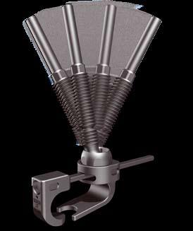
1 S U R G I C A L T E C H N I Q U E En POLYAXIAL SPINE SYSTEM S C O L I O S I S
2 INSTRUMENTATION A Pedicle hook starter A Laminar and transverse process hook starter A Compressor forceps for claw A Counter hook holder A Hook inserter A Screwdriver for hook head A T30 Screwdriver A T ratchet handle A Malleable rod, length 350 mm A French bender A Flexible guide A Nut holder and threaded extension breaker MS511 Rod Gripper A Nutdriver A Nutdriver shaft 2
3 S C O L I O S I S S U R G I C A L T E C H N I Q U E Section 1 CLAW FIXATION 1. Thoracic fixation using a pediculo-transverse claw: Thoracic fixation using a pediculo-laminar claw: Lumbar fixation using a lamino-laminar claw: Section 2 SCOLIOSIS REDUCTION 11 Section 3 DE-ROTATION 1. The Clement De-Rotation Connector: Implant presentation: Scoliosis reduction using DE-ROTATION connectors:
 : 2 types of thoracic claw are available : - Pediculo-transverse - Pediculo laminar (B02241104) Small polyaxial pedicular hook for")
 Contre crochet lamaire thoracique court (B02245407) Contre crochet lamaire thoracique long Only 1 type of lumbar claw is")
 Large polyaxial lumbar laminar hook for claw (B02242209) Short lumbar laminar counterhook (B02245209) Long lumbar")
4 LOW PROFILE POLYAXIAL SPINE SYSTEM Section 1 CLAW FIXATION Various claws are available according to the spinal area implanted (thoracic or lumbar) : 2 types of thoracic claw are available : - Pediculo-transverse - Pediculo laminar (B ) Small polyaxial pedicular hook for claw (B ) Large polyaxial pedicular hook for claw (B ) Short transverse counterhook (B ) Long transverse counterhook (B ) Contre crochet lamaire thoracique court (B ) Contre crochet lamaire thoracique long Only 1 type of lumbar claw is available : lamino-laminar claw (B ) Small polyaxial lumbar laminar hook for claw (B ) Medium polyaxial lumbar laminar hook for claw (B ) Large polyaxial lumbar laminar hook for claw (B ) Short lumbar laminar counterhook (B ) Long lumbar laminar counterhook 4


5 S C O L I O S I S S U R G I C A L T E C H N I Q U E 1. Thoracic fixation using a pediculo-transverse claw: A claw is a combination of a hook and a counter hook. Polyaxial pedicular hooks are available in 2 sizes 4mm (B ) or 6mm (B ). Transverse counter hooks are available in 2 sizes short stem (B ) or long stem (B ). Preparation for placement of the pedicle hook using the pedicle hook starter (A ). Preparation for placement of the transverse counter-hook using the transverse process hook starter (A ) at the superior part of the transverse process. Placement of the transverse counter hook using the counter hook holder (A ). 5
: Assembly of the hook onto the HOOK")


6 LOW PROFILE POLYAXIAL SPINE SYSTEM Setting of the hook on the HOOK INSERTER (A ): Assembly of the hook onto the HOOK INSERTER can be done directly from the final hook caddy. Position the tongs of the instrument onto the notches on both sides of the hook head. Firmly squeeze the handle to secure the tongs onto the hook head; next turn the knob (on handle) to lock in place. Positioning of the pedicle hook (without its threaded extension) using the hook inserter (A ). Stabilize the counter hook with the counter hook holder while sliding/ impacting the pedicle hook over the counter hook stem. 6


 and counter")


 to ease insertion.")


 for insertion")
7 S C O L I O S I S S U R G I C A L T E C H N I Q U E Screwing of the threaded extension onto the hook using the screwdriver for hook head (A ). To maintain claw stability during this step, leave the hook inserter (A ) and counter hook holder (A ) in place. NOTE: If insertion of the threaded extension into the hook is obstructed by the high position of the counter hook stem, slightly tilt the hook holder (pedicle hook still attached) to ease insertion. REMARK: The hook may be implanted preassembled with its threaded extension. In this case, be sure to leave adequate space (between threaded extension and hook) for insertion of the counter hook stem. Compression of the claw using the forceps for claw (A ). 7


8 LOW PROFILE POLYAXIAL SPINE SYSTEM Final tightening of hook head with the screwdriver for hook head (A ). Tightening of the threaded extension locks the counter-hook stem into the hook to ensure claw stability and a secure connection to the rod. The claws have the same threaded extension as the pedicle screws; therefore connection to the rod is the same. (Refer to PASS LP degenerative surgical technique chapter 2 paragraph 4). 8

 or 6mm (B02241106).")
. Preparation for placement of the pedicle hook: see chapter 1.1. page 5.")


9 S C O L I O S I S S U R G I C A L T E C H N I Q U E 2. THORACIC FIXATION USING A PEDICULO-LAMINAR CLAW: A claw is a combination of a hook and a counter hook. Polyaxial pedicular hooks are available in 2 sizes 4mm (B ) or 6mm (B ). Laminar counter-hooks are available in 2 sizes short stem (B ) or long stem (B ). Preparation for placement of the pedicle hook: see chapter 1.1. page 5. Preparation for placement of the supralaminar counter-hook using a Kerrisson punch. The creation of a large window is recommended to ease the insertion of the counter-hook. Placement of the laminar counter hook using the counter hook holder (A ). Positioning of the pedicle hook: see chapter 1.1. page 6 Screwing of the threaded extension onto the hook: see chapter 1.1. page 7 Compression of the claw: see chapter 1.1. page 7 Final tightening of hook head: see chapter 1.1. page 8 9

, medium")


10 LOW PROFILE POLYAXIAL SPINE SYSTEM 3. LUMBAR FIXATION USING LAMINO-LAMINAR CLAW: A claw is a combination of a hook and a counter hook. Polyaxial lumbar hooks are available in 3 sizes small (B ), medium (B ) or large (B ). Lumbar laminar counter-hooks are available in 2 sizes short stem (B ) or long stem (B ). Usually, the hook is placed in a infralaminar position and the counter-hook in a supra-laminar position. It is however possible to reverse the claw according to the needs of the construct. Preparation for placement of the laminar hook using the transverse process hook starter (A ). Preparation for placement of the supra-laminar counter-hook: see chapter 1.2 page 9 Placement of the laminar counter hook: see chapter 1.2 page 9 Positioning of the laminar hook using the hook inserter (A ): see chapter 1.1. page 6 Screwing of the threaded extension onto the hook: see chapter 1.1. page 7 Compression of the claw: see chapter 1.1. page 7 Final tightening of hook head: see chapter 1.1. page 7 10

, the reduction of the scoliosis includes the following steps. 1.")

11 S C O L I O S I S S U R G I C A L T E C H N I Q U E Section 2 REDUCTION DE SCOLIOSE The concept of the PASS LP system is to achieve a reduction of a deformity by simultaneously performing translation on two rods. Following the positioning of the anchorages (trefer to PASS LP Degenerative surgical technique, chapter 1 screw Positioning and Scoliosis surgical technique chapter 1 Claw fixation), the reduction of the scoliosis includes the following steps. 1.Rod selection and countouring Use the malleable rod (A ) to select rod length and determine rod contouring. Bend the rod using the French bender (A ). 2. Connector placement The standard connectors are symmetrical and thus reversible. Slide the connectors onto the rod. In most cases, the rods are placed on the median line. 3. Rod and connector insertion Drop the assembly over the flexible guide (or directly onto the threaded post of the screw) down to the screw head. Convex or concave rod can be placed first. No specific orientation needed for the rod. 11
 is")


.")

12 LOW PROFILE POLYAXIAL SPINE SYSTEM 4. Nut setting The nutholder (A ) is used to load each nut onto the threaded extension of the screw. Place the nut on the thread in order to leave the maximum freedom of movement for the rod maneuvers. 5. Rod orientation in sagittal plane Orientate the rod in the sagittal plane using the rod gripper (MS511). Block the rotation of the rods by tightening the 2 nuts located on the upper anchorages of the construct using the nutdriver shaft (A ). 12


.")

13 S C O L I O S I S S U R G I C A L T E C H N I Q U E 6. Reduction of the deformity The reduction is achieved through the progressive and alternative tightening of the nuts on both rods using the nutdriver shaft (A ) thus allowing to share the load on all anchorages. 7. Nut breaking Once the reduction is fully achieved (connectors flush against the anchorage), torque and break-off the nuts using the nutdriver (A ). While torqueing the nut, exert a downward force to contain the broken part in the instrument. 8. Threaded extension breaking Break the threaded extensions using the nut holder and threaded extension breaker (A ). IMPORTANT: Counting the broken parts is recommended to be certain no broken parts are left in the incision 13


14 LOW PROFILE POLYAXIAL SPINE SYSTEM Section 3 DE-ROTATION 1. THE CLEMENT DE-ROTATION CONNECTOR The De-Rotation Connector (ref. B ) is composed of a connector and a set screw. Can be used with both: PASS LP - Ø6.0 mm Rods PASS LP - Ø5.5 mm Rods Set screw Connector 2. IMPLANT PRESENTATION This De-Rotation Connector links the rod to the anchorage (screw) in a 2 steps manoeuvre: This technique is used to create a vertebral rotation manoeuvre. Lock the polyaxiality of the anchorage (screw) by tightening the break away nut Lock the translation/rotation movement of the connector on the rod by tightening the set screw The De-Rotation Connectors are used on the vertebras at the apex portion of the deformity on both concave and convex rods. 14


15 S C O L I O S I S S U R G I C A L T E C H N I Q U E The concave De-Rotation Connector is locked on the spine in the coronal plane by tightening the set screw, preventing anterior movement of the connector The convex De-Rotation Connector is kept loose in order to allow the connector to freely rotate around the rod on the convex side of spine. T30 screwdriver (A ) with the T-handle (A ) The progressive tightening of the self-breaking nut creates an anterior-posterior translation of the spine. This translation is more important on the concave side of the spine allowing for vertebral rotation. 15


16 LOW PROFILE POLYAXIAL SPINE SYSTEM 3. SCOLIOSIS REDUCTION USING DE-ROTATION CONNECTORS : In the case you wish to use de-rotation connectors, the reduction of the scoliosis includes the following steps. 3.A Surgical Technique for a thoracic curve a. Rod selection and countouring: see chapter 2 page 11 b. Connector placement Use the derotation connectors for anchorage in the apex zone of the deformity and the standard connectors on all other anchorage points. IMPORTANT: The De-Rotation connectors are asymmetrical and must be implanted with the connector set screw facing up. The rods are placed in a median position in relation to the anchorage. Slide the connectors onto the rod in the correct order and direction. c.rod and connector insertion: see chapter 2 page 11 d. Nut setting: see chapter 2 page 12 e. Rod orientation in sagittal plane: see chapter 2 page 12 f. Positioning of the concave De-Rotation Connectors Lock the concave De-Rotation Connectors in the coronal plane by tightening the set screws with the T30 screwdriver (A ), avoiding anterior movement. The convex De-Rotation Connector set screws are kept loose at this stage. Coronal Plane 16
17 S C O L I O S I S S U R G I C A L T E C H N I Q U E g. Reduction of the deformity by tightening the nuts on all anchorages: see section 2 page 13 The vertebral derotation is obtained at the end of tightening when the concave anchorage is flush to the De-Rotation Connector. h. Locking the convex connector set screws IMPORTANT : Now lock the convex connector set screws with the T30 screwdriver (A ) equipped with the T handle (A ). Note: All set screws should now be tight i. Torqueing and Breaking the nuts: see chapter 2 page 13 j. Breaking the threaded extensions see chapter 2 page 13 3.B. Surgical Technique for thoraco-lumbar or lumbar curves To get the best results, reduction must be performed in a certain manner: Translation followed by compression and derotation that cannot be performed simultaneously. We recommend the use of de-rotation connectors at all levels on both rods. Translation move on convex rod After you orientate and set the rods, progressively tighten the breakaway nuts on convex rod, keeping set screws unlocked. Convex compression Perform the convex compression gradually on the convex anchorages. Lock de-rotation connectors by tightening the set screws. Concave vertebral derotation Clear the apex zone which needs to be derotated by unlocking the intermediate convex set screws, BUT still keeping the anchorages of the extremities of the compressed convex zone locked, to maintain the compression previously applied. Place the concave derotation connectors in the coronal plane and lock the set screws. Progressively tighten the concave breakaway nuts to perform the derotation. Retighten the convex derotation connector set screws. Then finish the procedure repeating points i and j as previously described. 17
5 46 00 55 55 Fax +33 (0)5 46 00 55 77 FDA cleared. Ref. C02D02012-v02 Sept 2009 Medicrea. All rights reserved. Patented products.")
18 Headquarters: MEDICREA 24 porte du Grand Lyon NEYRON - FRANCE Tél. +33 (0) Fax +33 (0) customerservice@medicrea.com Manufacturer: MEDICREA Technologies Z.I. Chef de Baie LA ROCHELLE - FRANCE Tel. +33 (0) Fax +33 (0) FDA cleared. Ref. C02D02012-v02 Sept 2009 Medicrea. All rights reserved. Patented products. MEDICREA and PASS are Medicrea registered trademarks RCS La Rochelle SAS au capital de Euros Distribué par : ALMED LISTED NYSE
POLYAXIAL SPINE SYSTEM SURGICAL TECHNIQUE
 POLYAXIAL SPINE SYSTEM SURGICAL TECHNIQUE P O L Y A X I A L S P I N E S Y S T E M POLYAXIALITY STABILITY EFFICIENCY All the implants offer the Polyaxiality, including Hooks, Claws, Sacral Plates and of
TRULY POLYAXIAL, SOLID AND POWERFUL
 S U R G I C A L T E C H N I Q U E V2 TRULY POLYAXIAL, SOLID AND POWERFUL P O L Y A X I A L S P I N E S Y S T E M a decade of results P O L Y A X I A L S P I N E S Y S T E M TRULY POLYAXIAL, SOLID AND POWERFUL
SURGICAL TECHNIQUE. SpineTune THORACO-LUMBAR POSTERIOR OSTEOSYNTHESIS SYSTEM
 SURGICAL TECHNIQUE SpineTune TM TL THORACO-LUMBAR POSTERIOR OSTEOSYNTHESIS SYSTEM SURGICAL TECHNIQUE SpineTune TM TL Table of Contents page Step 1 - Site preparation.......................................................................................
Optima ZS Spinal Fixation System
 Surgical Technique Optima ZS Spinal Fixation System The low-profile, in-line, polyaxial pedicle screw system. Optima ZS Surgical Technique 1 Optima ZS Spinal Fixation System The Optima ZS Spinal Fixation
A M E D S MART SOLUTIONS FAMILY MEMBER
 A M E D S MART SOLUTIONS FAMILY MEMBER Based in the United Kingdom, Medsmart Solutions is a dynamic 100% British owned company which is dedicated to the manufacture and supply of an extensive range of
Xia 3 Reference Guide. Version 3-August 2015
 Xia 3 Reference Guide Xia 3 Reference Guide Version 3-August 2015 Table of Contents Implants 03 Blocker 03 Monoaxial Screws 04 Polyaxial Screws 05 Uniplanar Screws 06 Iliac Bolts 07 Rod-to-Rod Connectors
URS Degen. Top loading pedicle screw system for posterior stabilization.
 URS Degen. Top loading pedicle screw system for posterior stabilization. Technique Guide This publication is not intended for distribution in the USA. Table of Contents Introduction URS Degen 2 AO Principles
Thoracolumbar Solutions. Vitality Spinal Fixation System. Surgical Technique Guide
 Thoracolumbar Solutions Vitality Spinal Fixation System Surgical Technique Guide Vitality Spinal System Surgical Technique Vitality Spinal System Surgical Technique Description, Indications and Contraindications...
Top Loading Pedicle Screw and Hook System for Posterior Stabilization. URS System. Surgical Technique
 Top Loading Pedicle Screw and Hook System for Posterior Stabilization URS System Surgical Technique Image intensifier control This description alone does not provide sufficient background for direct use
Thoracolumbar Solutions. Polaris. Deformity System. Trivium. Derotation System. Surgical Technique Guide
 Polaris Deformity System Thoracolumbar Solutions Trivium Derotation System Surgical Technique Guide 2 Polaris Deformity System and Trivium Derotation System Surgical Technique Guide Polaris Deformity System
REXIOUS SPINAL SYSTEM
 REXIOUS SPINAL SYSTEM SURGICAL TECHNIQUE www.diomedical.com. Site Preparation. Screw Insertion 3. Rod Preparation and Insertion 4. Rod Instruction 5. Set screw Insertion 6. Compression, Distraction & Rotation
Surgical Technique. Deformity - Degenerative. Interbody Fusion. Tumour - Trauma. Cervical. Emerging Technology
 Surgical Technique Deformity - Degenerative Interbody Fusion Tumour - Trauma Cervical Emerging Technology MONARCH SPINE SYSTEM Contents Introduction & Philosophy 2 Surgical Technique Monarch Bolts with
Vertebral Body Derotation System Guide and Ordering Information
 Vertebral Body Derotation System Guide and Ordering Information Introduction DePuy Spine continues to support the goal of providing solutions to surgeon challenges when treating spinal disorders. Collaborating
Surgical Technique ANAX TM OCT. Spinal System
 Surgical Technique ANAX TM OCT Spinal System Product Overview Occipital plate Medial occipital plate (Small, Medium, Large) Lateral occipital plate (Small, Medium, Large) Cortical screw (D4.5mm), Rescue
Pangea Degenerative Spine System. Top Loading Preassembled Pedicle Screw System for Posterior Stabilization of the Thoracolumbar Spine.
 Technique Guide Pangea Degenerative Spine System. Top Loading Preassembled Pedicle Screw System for Posterior Stabilization of the Thoracolumbar Spine. Contents Introduction AO ASIF Principles 4 Indications
Reflex TM Surgical Technique. Anterior Cervical Plate
 Reflex TM Surgical Technique Anterior Cervical Plate Surgical Technique Acknowledgement: Stryker Spine extends their thanks to the following surgeons for their participation in the development of the Reflex
Aesculap Spine S 4 Spinal System. Instrumentation Guide
 Aesculap Spine S 4 Spinal System Instrumentation Guide S 4 Spinal System S 4 From initial conception, the S 4 Spinal System was developed to meet the spine surgeon s need for an extremely low profile and
Cervical Solutions. Lineum OCT. Spine System. Surgical Technique Guide
 Cervical Solutions Lineum OCT Spine System Surgical Technique Guide 2 Lineum OCT Spine System Surgical Technique Guide Designed to encourage optimal screw placement and procedural efficiency Lineum OCT
BLACKBIRD Spinal System
 BLACKBIRD Spinal System Cervical-Thoracic Spinal Fixation System The ChoiceSpine BLACKBIRD Cervical-Thoracic Spinal Fixation System is a comprehensive system for posterior fixation of the cervical and upper
Interlagos Retractor System Surgical Technique
 Interlagos Retractor System Surgical Technique TABLE OF CONTENTS Instructions for Use Design Rationale Surgical Technique 1. Pre-Operative Preparation 2. Pedicle Preparation 3. Primary Retraction 4. Secondary
Gibralt. Occipito-Cervico Thoracc System. Operative Technique
 Gibralt Occipito-Cervico Thoracc System Operative Technique TABLE OF CONTENTS GIBRALT...1 OPERATIVE TECHNIQUE OVERVIEW...2 HOOK PLACEMENT...2 SCREW PLACEMENT...2 DETAILED OPERATIVE TECHNIQUE...4 PLACEMENT
S 4. Aesculap. Spinal System. Percutaneous Approach Surgical Technique. Aesculap Spine
 Aesculap Percutaneous Approach Surgical Technique S 4 Spinal System Aesculap Spine S 4 Spinal System Small The S 4 Spinal System features a revolutionary pressure vessel design capable of delivering unmatched
VBOSS Surgical Technique
 VBOSS Surgical Technique 1 2 CONTENT 1. System Description 4 1.1 Implants 4 1.2 Instruments 6 2. Indications 11 3. Patient Position 11 4. Surgical Approach 12 4.1 Choice of adequate Parallel Distractor
Technique Guide. Synapse System. An enhanced set of instruments and implants for posterior stabilization of the cervical and upper thoracic spine.
 Technique Guide Synapse System. An enhanced set of instruments and implants for posterior stabilization of the cervical and upper thoracic spine. Table of Contents Introduction Synapse System 2 AO Principles
SYnaPSe oct SYSteM. An enhanced set of instruments and implants for posterior stabilization of the upper spine
 SYnaPSe oct SYSteM An enhanced set of instruments and implants for posterior stabilization of the upper spine SurgIcal technique Table of Contents Introduction SYNAPSE OCT System 2 AO Principles 5 Indications
UNIQUE PATIENTS SPECIFIC INDICATIONS IN ONE SYSTEM. Surgical Technique
 UNIQUE PATIENTS SPECIFIC INDICATIONS IN ONE SYSTEM Surgical Technique Joint Spine Sports Med Mecta-C Plate Surgical Technique 2 INDEX 1. INTRODUCTION 4 1.1 Mecta-C Cervical Plates 4 1.2 Bone Screws 4 1.3
CD HORIZON REDUCTION MULTI AXIAL SCREW. Spinal System Technical Guide
 CD HORIZON REDUCTION MULTI AXIAL SCREW Spinal System Technical Guide T E C H N I C A L G U I D E CD HORIZON REDUCTION MULTI AXIAL SCREW Spinal System The following describes reduction of a spondylolisthesis
UNIQUE PATIENTS SPECIFIC INDICATIONS IN ONE SYSTEM. Surgical Technique
 UNIQUE PATIENTS SPECIFIC INDICATIONS IN ONE SYSTEM Surgical Technique Joint Spine Sports Med Mecta-C Plate Surgical Technique 2 INDEX 1. INTRODUCTION 4 1.1 Mecta-C Cervical Plates 4 1.2 Bone Screws 4 1.3
Synapse System. An enhanced set of instruments and implants for posterior stabilization of the upper spine.
 Synapse System. An enhanced set of instruments and implants for posterior stabilization of the upper spine. Technique Guide 100º Instruments and implants approved by the AO Foundation Table of Contents
Virage OCT Spinal Fixation System
 Virage OCT Spinal Fixation System Virage OCT Spinal Fixation System Change Your Perspective Become a Part of the Posterior Fixation Revolution The Virage System is an Occipital-Cervico-Thoracic (OCT) spinal
Technique Guide. Occipito-Cervical Fusion System. Implants and instruments designed to optimize fixation to the occiput.
 Technique Guide Occipito-Cervical Fusion System. Implants and instruments designed to optimize fixation to the occiput. Table of Contents Introduction Overview 2 AO ASIF Principles 4 Indications and Contraindications
Technique Guide. Synapse System. An enhanced set of implants and instruments for posterior stabilization of the cervical and upper thoracic spine.
 Technique Guide Synapse System. An enhanced set of implants and instruments for posterior stabilization of the cervical and upper thoracic spine. Image intensifier control Warning This description alone
ACLP Anterior Cervical Locking Plate System TECHNIQUE GUIDE
 ACLP Anterior Cervical Locking Plate System TECHNIQUE GUIDE Instruments and implants approved by the AO Foundation ACLP Anterior Cervical Locking Plate System The ACLP System is designed to reduce the
Occipito-Cervical Fusion System
 Implants and Instruments designed to enhance Fixation to the Occiput Occipito-Cervical Fusion System Surgical Technique Image intensifier control This description alone does not provide sufficient background
QUANTUM SPINAL. Presenter: John Perala, Product Manager. August 14, 2006
 QUANTUM SPINAL ROD SYSTEM Key Features Presenter: John Perala, Product Manager August 14, 2006 Fixed Screw Sizes 475 4.75, 25-40mm 7.75, 30-50mm 5.75, 25-40mm 875 8.75, 30-40mm 6.75, 30-50mm Polyaxial
OPERATIVE TECHNIQUE COVER IMAGE OPTIONAL (DETAIL) IMAGE FIREBIRD NXG. spinal fixation system
 IMAGE FIREBIRD NXG. spinal fixation system") OPERATIVE TECHNIQUE COVER IMAGE OPTIONAL (DETAIL) IMAGE FIREBIRD NXG spinal fixation system TABLE OF CONTENTS Introduction 1 Operative Technique 2 Reduction Body Technique 18 Implants and Instruments 24
OPERATIVE TECHNIQUE COVER IMAGE OPTIONAL (DETAIL) IMAGE FIREBIRD NXG spinal fixation system TABLE OF CONTENTS Introduction 1 Operative Technique 2 Reduction Body Technique 18 Implants and Instruments 24
CSLP Variable Angle. For Use with the Cervical Spine Locking Plate System TECHNIQUE GUIDE. Self-drilling Screw. Variable Screw Angulation
 CSLP Variable Angle For Use with the Cervical Spine Locking Plate System TECHNIQUE GUIDE Self-drilling Screw Variable Screw Angulation Original Instruments and Implants of the Association for the Study
TherAdapt Products Inc. (800) phone (866) fax
 phone (866) fax") TherAdapt Products Inc. (800) 261-4919 phone (866) 892-2478 fax www.theradapt.com Posture Chair Please read all of the following information before using this product. TherAdapt Products Inc. has designed
TherAdapt Products Inc. (800) 261-4919 phone (866) 892-2478 fax www.theradapt.com Posture Chair Please read all of the following information before using this product. TherAdapt Products Inc. has designed
ACCS Anterior Cervical Compression System TECHNIQUE GUIDE
 ACCS Anterior Cervical Compression System TECHNIQUE GUIDE Original Instruments and Implants of the Association for the Study of Internal Fixation AO ASIF ACCS Anterior Cervical Compression System The Anterior
D. Greg Anderson, MD Thomas Jefferson University Hospital Philadelphia, PA
 Surgical Technique D E S I G N I N G S U R G E O N S D. Greg Anderson, MD Thomas Jefferson University Hospital Philadelphia, PA Robert Heary, MD University of Medicine and Dentistry of New Jersey Newark,
VBOSS. Surgical Technique. Vertebral Body Support System
 VBOSS Surgical Technique Vertebral Body Support System 1. System Description 1.1 Implants...3 1.2 Instruments...4 2. Indications...8 3. Patient Position...8 4. Surgical Approach 4.1 Choice of adequate
Lineum OCT Spine System
 Surgical Technique Lineum OCT Spine System Designed to Encourage Optimal Screw Placement and Procedural Efficiency Game Changing Translation Screw 3.0mm of medial/lateral translation encourages optimal
Ascent. Posterior Occipital Cervico-Thoracic (POCT) System
 System") Ascent Posterior Occipital Cervico-Thoracic (POCT) System Ascent Posterior Occipital Cervico-Thoracic (POCT) System VERSATILITY, RELIABILITY AND SIMPLICITY FOR COMPLEX SPINAL PROCEDURES The Ascent POCT
Ascent Posterior Occipital Cervico-Thoracic (POCT) System Ascent Posterior Occipital Cervico-Thoracic (POCT) System VERSATILITY, RELIABILITY AND SIMPLICITY FOR COMPLEX SPINAL PROCEDURES The Ascent POCT
SYNAPSE SYSTEM An enhanced set of implants and instruments for posterior stabilization of the cervical and upper thoracic spine
 SYNAPSE SYSTEM An enhanced set of implants and instruments for posterior stabilization of the cervical and upper thoracic spine Instruments and implants approved by the AO Foundation. This publication
ACP 1. Anterior Cervical Plating System. Surgical Technique
 ACP 1 Anterior Cervical Plating System Surgical Technique Table of Contents System Overview.... 3 Patient Positioning and Exposure.... 5 Implant Selection and Preparation... 7 Screw Hole Preparation...
Lateral Mass Fixation Surgical Technique. and Product Catalog. Distribution For EU Only
 Lateral Mass Fixation Surgical Technique and Product Catalog Distribution For EU Only INTRODUCTION The MOUNTAINEER Occipito-Cervico-Thoracic Spinal System offers a comprehensive solution for rigid posterior
Technique Guide. 4.5 mm Cannulated Screws. Part of the Synthes Cannulated Screw System.
 Technique Guide 4.5 mm Cannulated Screws. Part of the Synthes Cannulated Screw System. TableofContents Introduction 4.5 mm Cannulated Screws 2 AO Principles 3 Indications 4 Surgical Technique Surgical
OCCIPITO-CERVICAL FUSION SYSTEM Implants and instruments designed to optimize fixation to the occiput
 OCCIPITO-CERVICAL FUSION SYSTEM Implants and instruments designed to optimize fixation to the occiput Instruments and implants approved by the AO Foundation. This publication is not intended for distribution
3.5 mm Cannulated Screw Technique Guide
 3.5 mm Cannulated Screw Technique Guide An Integral Part of the SYNTHES Cannulated Screw System Original Instruments and Implants of the Association for the Study of Internal Fixation AO ASIF The 3.5 mm
Aviator Anterior Cervical Plating System System Overview. Visual and tactile confirmation Increased Angulation Simplified instrumentation
 Aviator Anterior Cervical Plating System System Overview Visual and tactile confirmation Increased Angulation Simplified instrumentation The Aviator anterior cervical plating system offers a unique double
6.5 mm and 7.3 mm Cannulated Screws Technique Guide
 6.5 mm and 7.3 mm Cannulated Screws Technique Guide An Integral Part of the SYNTHES Cannulated Screw System Original Instruments and Implants of the Association for the Study of Internal Fixation AO ASIF
Technique Guide. 7.0 mm Cannulated Screws. Part of the Synthes Cannulated Screw System.
 Technique Guide 7.0 mm Cannulated Screws. Part of the Synthes Cannulated Screw System. Table of Contents Introduction 7.0 mm Cannulated Screws 2 AO Principles 3 Indications 4 Surgical Technique Surgical
PRODUCT SUMMARY. 80 Total Angulation
 PRODUCT SUMMARY 80 Screw Angulation 40 40 80 Total Angulation 3 Directions of Freedom in Cross Link Low Profile Screws Sizes Available in 3.5mm and 4.0 mm diameters Accomodates 3.5 mm rod Self Drilling,
VECTRA SURGICAL TECHNIQUE. Anterior cervical plate system. This publication is not intended for distribution in the USA.
 VECTRA Anterior cervical plate system This publication is not intended for distribution in the USA. SURGICAL TECHNIQUE Image intensifier control This description alone does not provide sufficient background
The Percutaneous Reduction Forceps Technique Guide
 The Percutaneous Reduction Forceps Technique Guide Indications + Product Overview Introduction The Percutaneous Reduction Forceps The Percutaneous Reduction Forceps facilitate standard technique for fixation
Aviator Anterior Cervical Plating System Surgical Technique
 Aviator Anterior Cervical Plating System Surgical Technique Table of Contents System Overview...3-4 Patient Positioning and Exposure...5 Implant Selection and Preparation.... 6-7 Screw Hole Preparation....
Part Name Part Number Quantity
 Part Name Part Number Quantity Flex Arm Adapter Triangular 03.612.013 2 3mm Drill Bit with Stop 16mm 324.16 1 2.5mm Drill Bit with Stop 13mm 324.152 1 2.5mm Drill Bit with Stop 16mm 324.155 2 2.5mm Drill
Occipito-Cervical Fusion System. Implants and instruments designed to optimize fixation to the occiput.
 Occipito-Cervical Fusion System. Implants and instruments designed to optimize fixation to the occiput. Technique Guide This publication is not intended for distribution in the USA. Instruments and implants
MaxAn Anterior Cervical Plate System
 Surgical Technique MaxAn Anterior Cervical Plate System Designed to Help Minimize the Potential for Adjacent Level Ossification Allows for screw placement up to 30 cephalad on the superior end of the plate
Vectra, Vectra-T and Vectra-One. Anterior cervical plating for spinal fusion.
 Vectra, Vectra-T and Vectra-One. Anterior cervical plating for spinal fusion. Technique Guide Instruments and implants approved by the AO Foundation Table of Contents Introduction Vectra, Vectra-T and
CHARLOTTE CLAW Plate Compression Locking Arthrodesis by Wright SURGICAL TECHNIQUE
 CHARLOTTE CLAW Plate Compression Locking Arthrodesis by Wright SURGICAL TECHNIQUE Contents Chapter 1 1 Chapter 2 2 2 2 3 4 5 6 Appendix A 7 Preoperative Planning Surgical Technique Calcaneal Cuboid Arthrodesis
Integra. Tibio Talo Calcaneus Plate SURGICAL TECHNIQUE
 Integra Tibio Talo Calcaneus Plate SURGICAL TECHNIQUE Table of Contents Indications...02 Contraindications...02 Description...02 Surgical Technique...03 Step 1: Articular Surfaces Preparation...03 Step
Back to health. Back to work. Back to life.
 TECHNIQUE Back to health. Back to work. Back to life. U PLUS 90 INSTRUMENTATION OVERVIEW W&H IMPLANTMED POWER UNIT OVERVIEW Low-profile Primary Guides Compresses the U-clip to match rib thickness Clamps
ASSEMBLY OF THE TWO PROSTHETIC COMPONENTS
 APPENDIX 1 ASSEMBLY OF THE TWO PROSTHETIC COMPONENTS The assembly of the two components of a PFM-Revision 2 nd generation stem (Revitan straight stem) stem is realised with a torque wrench providing a
ISO Plate SURGICAL TECHNIQUE
 MINI MAXLOCK EXTREME ISO Plate SURGICAL TECHNIQUE Contents Table of Contents Key Design Features 2 Surgical Technique 3 Implants and Instruments 8 Key Design Features The MINI MAXLOCK EXTREME ISO (Intraosseous
SURGICAL TECHNIQUE. C-Plate ANTERIOR CERVICAL PLATE
 SURGICAL TECHNIQUE C-Plate ANTERIOR CERVICAL PLATE SURGICAL TECHNIQUE C-Plate Table of contents page Step 1 - Disc location and vertebral space preparation........................................ 3 Step
VECTRA. SURGICAL TECHNIQUE. Anterior cervical plate system. This publication is not intended for distribution in the USA.
 VECTRA. Anterior cervical plate system. This publication is not intended for distribution in the USA. SURGICAL TECHNIQUE Contents Indications and contraindications Implants Vario Case Instruments Surgical
Orthopedic Bone Nail System Universal Humeral Nail
 Orthopedic Bone Nail System Universal Humeral Nail Surgical Technique Manual Note: The surgical procedures should be performed under the guidance of qualified skilled orthopedic surgeons, and this surgical
TORNIER MAXLOCK EXTREME. Clavicle Plating System SURGICAL TECHNIQUE
 TORNIER MAXLOCK EXTREME Clavicle Plating System SURGICAL TECHNIQUE 2 Table of Contents: Key Design Features...4 Surgical Technique...5 Implants & Instruments...9 3 Key Design Features There are 7 anatomically
Technique Guide. Quadrilateral Surface Plates 3.5. Part of the Low Profile Pelvic System 3.5.
 Technique Guide Quadrilateral Surface Plates 3.5. Part of the Low Profile Pelvic System 3.5. Table of Contents Introduction Quadrilateral Surface Plates 3.5 2 AO Principles 4 Indications 5 Surgical Technique
OPERATIVE TECHNIQUE CENTURION POSTERIOR OCCIPITAL CERVICO-THORACIC (POCT) SYSTEM
 SYSTEM") OPERATIVE TECHNIQUE CENTURION POSTERIOR OCCIPITAL CERVICO-THORACIC (POCT) SYSTEM TABLE OF CONTENTS Introduction 2 System Overview 3 Cervical Operative Technique 4 Thoracic Operative Technique 10 Thoracic
OPERATIVE TECHNIQUE CENTURION POSTERIOR OCCIPITAL CERVICO-THORACIC (POCT) SYSTEM TABLE OF CONTENTS Introduction 2 System Overview 3 Cervical Operative Technique 4 Thoracic Operative Technique 10 Thoracic
OPERATIVE TECHNIQUE RIVAL REDUCE FRACTURE PLATING SYSTEM. foot & ankle trauma procedures
 OPERATIVE TECHNIQUE RIVAL REDUCE FRACTURE PLATING SYSTEM foot & ankle trauma procedures INTRODUCTION 3 SYSTEM DESCRIPTION 3 TECHNICAL DETAILS 4 SALES AND MARKETING CONFIGURATION 5 OPERATIVE TECHNIQUE 7
Small Plate and Screw System SURGICAL TECHNIQUE
 MINI MAXLOCK EXTREME Small Plate and Screw System SURGICAL TECHNIQUE Contents Key Design Features 2 Surgical Technique 3 Implants and Instruments 9 Proper surgical procedures and techniques are the responsibility
Adjusting Ibanez SR405QM Truss Rod
 Adjusting Ibanez SR405QM Truss Rod High tension caused by the strings can cause the wood of the fret board to bow. This bowing can become so extreme it becomes difficult or impossible to play on due to
surgical technique addendum
 s h o u l d e r Solutions by Tornier Aequalis reversed II shoulder system surgical technique addendum Aequalis reversed II threaded post baseplate surgical technique addendum s u r g i c a l t e c h n
Reflex Hybrid System Overview
 Spine Reflex Hybrid System Overview Anterior Cervical Plating System Introduction The Reflex Hybrid ACP System offers a low-profile anterior cervical plate along with a selection of bone screw types to
PAC PLATE A N T E R I O R C E RV I CA L P L AT E SYST E M S U R G I C A L T E C H N I Q U E
 PAC PLATE A N T E R I O R C E RV I CA L P L AT E SYST E M S U R G I C A L T E C H N I Q U E PAC PLATE ANTERIOR CERVICAL PLATE SYSTEM Table of Contents INTRODUCTION System Overview... 1 SURGICAL TECHNIQUE
2. Connect driver to power source leads. After connections are made, place driver above ceiling. SEE MINIMUM SPACE REQUIREMENTS BELOW.
 INSTALLATION INSTRUCTIONS INSTALLATION: 1. Cut proper opening in ceiling. Round: 140mm Ø, Square: 140mm x 140mm 140mm Ø 140mm x 140mm 2. Connect driver to power source leads. After connections are made,
7.0 mm Cannulated Screws
 Part of the DePuy Synthes Cannulated Screw System 7.0 mm Cannulated Screws Surgical Technique Table of Contents Introduction 7.0 mm Cannulated Screws 2 AO Principles 3 Indications 4 Surgical Technique
Surgical Technique. and Ordering Information
 Surgical Technique and Ordering Information INTRODUCTION CONTENTS The SKYLINE Anterior Cervical Plate provides a versatile system of implants and instruments to accommodate the needs and individual preferences
Technique Guide. Modular Sternal Cable System. Flexibility and strength in sternal closure and repair.
 Technique Guide Modular Sternal Cable System. Flexibility and strength in sternal closure and repair. Table of Contents Introduction Overview 2 Indications and Contraindications 3 Surgical Technique A.
Universal Humeral Nail
 990210009 INDEX Indications Preoperative Planning Patient Position Surgical Technique - Step 1 Open Humerus - Step 2 Calibrate The Nail - Step 3 Insert Nail - Step 4 Proximal Locking - Step 5 Assemble
VariAxFibula. Fibula Fractures. Locking Plate System. Operative Technique
 Foot and Ankle VariAxFibula Locking Plate System Operative Technique Fibula Fractures Distal Fibula Fracture Repair Polyaxial Locking Technology Low Profile Design VariAx Fibula Locking Plate System Contributing
Integra. Capture Screw System SURGICAL TECHNIQUE
 Integra Capture Screw System SURGICAL TECHNIQUE Table of Contents Indications... 2 Contraindications... 2 System Description... 2 System Features... 2 Cannulated Low-Profile Screws (AC-Series) Overview...
ThinLine Anterior Cervical Plate
 ThinLine Anterior Cervical Plate Surgical Technique Solutions by the people of Zimmer Spine. zimmerspine.com Designed for those times when less means more. From the people of Zimmer Spine. ThinLine is
Ulna Shortening System 2.5
 SURGICAL TECHNIQUE STEP BY STEP Ulna Shortening System 2.5 APTUS Wrist 2 Ulna Shortening System 2.5 Contents 3 Introduction Product Materials Indications Contraindications Color Coding 4 General Instrument
Treace Medical Concepts Plating System
 Treace Medical Concepts Plating System Multiplanar Fixation System Surgical Technique Lapidus and 1 st MTP Fusion Lapidus Fusion Surgical Approach 1. Perform a longitudinal incision dorsally over the 1
Knee Nail for Retrograde Femoral Mode
 Surgical Technique *smith&nephewt TRIGEN IM Nail System Knee Nail for Retrograde Femoral Mode Table of Contents Indications 2 Surgical Technique 3 TRIGEN STABLE-LOK Nut & Washer Surgical Technique 16 TRIGEN
Storage Cabinets 9000 Series Assembly Instructions
 Storage Cabinets 9000 Series Assembly Instructions Thank you for selecting Salsbury s storage cabinets. We are confident that the quality and construction of the cabinets will prove to be a good investment.
STEINBERGER TRANSTREM (TYPE 2) TECHNICAL DOCUMENT
 TECHNICAL DOCUMENT") STEINBERGER TRANSTREM (TYPE 2) TECHNICAL DOCUMENT These instructions apply to newer style TransTrems only (non-threaded ball type or modified threaded ball type). For purposes of discussion, these TransTrems
STEINBERGER TRANSTREM (TYPE 2) TECHNICAL DOCUMENT These instructions apply to newer style TransTrems only (non-threaded ball type or modified threaded ball type). For purposes of discussion, these TransTrems
MTP Set SURGICAL TECHNIQUE
 MINI MAXLOCK EXTREME MTP Set SURGICAL TECHNIQUE Contents Table of Contents Key Design Features 3 Surgical Technique Standard MTP Plate 4 MTP Plate with POCKETLOCK Technology 10 Implants and Instruments
Replacing the Reciprocator on the SWF Compact Series Machine (601C and 1201C)
") Follow the instructions below to replace the reciprocator in the SWF Compact series machines. The tools required can be found in the tool kit that came with the machine. Preparation 1. First, place the
Follow the instructions below to replace the reciprocator in the SWF Compact series machines. The tools required can be found in the tool kit that came with the machine. Preparation 1. First, place the
Technique Guide. LCP Pilon Plate 2.7/3.5
 Technique Guide LCP Pilon Plate 2.7/3.5 LCP Pilon Plate 2.7/3.5 Table of contents Indications 3 Implants 4 Instruments 5 Surgical technique 6 Implant removal 12 Image intensifier control Warning This
OPERATION AND MAINTENANCE HANDBOOK D407270XA
 OPERATION AND MAINTENANCE HANDBOOK D407270XA vers. 1.0 Thank you for choosing one of Silca s high quality key cutting machines. This machine has been designed, tested and produced in our factory using
VariAx Foot Locking Plate System
 VariAx Foot Locking Plate System Operative Technique Trauma and Deformity Correction Polyaxial Locking Technology Comprehensive Calcaneal Fracture Plates Table of Contents 1. Introduction 3 2. Overview
Digital Compression Screw
 Digital Compression Screw Surgical Technique Contents Product The BioPro Digital Compression Screw is a stainless steel lag screw designed for digital fusions. Table of contents Indications & Contraindications
Part of the DePuy Synthes Cannulated Screw System. 3.5 mm Cannulated Screws
 Part of the DePuy Synthes Cannulated Screw System 3.5 mm Cannulated Screws Surgical Technique Table of Contents Introduction 3.5 mm Cannulated Screws 2 AO Principles 3 Indications 4 Surgical Technique
ASSEMBLY MANUAL POLAR GRIPPERS
 ASSEMBLY MANUAL POLAR GRIPPERS 2012 TABLE OF CONTENTS TABLE OF CONTENTS... 2 PRESENTATION... 3 AMG GRIPPERS FOR ROBOTS... 4 PREPARATION OF THE PARTS... 5 PREPARING A MAIN BOOM... 6 PREPARING A SECONDARY
,... - '-. ) * cited by examiner US B2. c12) United States Patent Wolinsky et al. (10) Patent No.: US 9,161,787 B2
 * cited by examiner US B2. c12) United States Patent Wolinsky et al. (10) Patent No.: US 9,161,787 B2") 111111 1111111111111111111111111111111111111111111111111111111111111 US009161787B2 c12) United States Patent Wolinsky et al. (10) Patent No.: (45) Date of Patent: Oct. 20, 2015 (54) VERTEBRAL BODY REDUCTION
111111 1111111111111111111111111111111111111111111111111111111111111 US009161787B2 c12) United States Patent Wolinsky et al. (10) Patent No.: (45) Date of Patent: Oct. 20, 2015 (54) VERTEBRAL BODY REDUCTION
VariAx Fibula Locking Plate System
 VariAx Fibula Locking Plate System Operative Technique Distal Fibula Fracture Repair Polyaxial Locking Technology Low Profile Design 1 Contributing Surgeon: Bradley R. Merk, MD Associate Professor of Orthopaedic