VECTRA SURGICAL TECHNIQUE. Anterior cervical plate system. This publication is not intended for distribution in the USA.
|
|
|
- Derrick O’Brien’
- 6 years ago
- Views:
Transcription


1 VECTRA Anterior cervical plate system This publication is not intended for distribution in the USA. SURGICAL TECHNIQUE
2 Image intensifier control This description alone does not provide sufficient background for direct use of DePuy Synthes products. Instruction by a surgeon experienced in handling these products is highly recommended. Processing, Reprocessing, Care and Maintenance For general guidelines, function control and dismantling of multi-part instruments, as well as processing guidelines for implants, please contact your local sales representative or refer to: For general information about reprocessing, care and maintenance of Synthes reusable devices, instrument trays and cases, as well as processing of Synthes non-sterile implants, please consult the Important Information leaflet (SE_023827) or refer to:
3 Contents Introduction Vectra 2 Indications and contraindications 4 Product Information Implants 5 Vario Case 8 Instruments 9 Surgical Technique Option A Variable angle, self-drilling screw 14 Option B Fixed angle, self-drilling screw 16 Option C Variable angle, self-tapping screw 18 Option D Fixed angle, self-tapping screw 20 Implant removal 22 Vectra Anterior cervical plate system Surgical Technique DePuy Synthes 1
 Integral Elgiloy clips lock the screws to the plate Screws Screws are color coded to identify function and diameter 1 Regular screw diameter 4.")

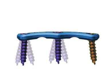
4 Vectra. The flexible and easy-to-use anterior cervical plate system. Plates Integrated blocking mechanism Prelordosed Large graft visibility window 16.5 mm wide and 2.5 mm thin Titanium alloy plate (TAN) Integral Elgiloy clips lock the screws to the plate Screws Screws are color coded to identify function and diameter 1 Regular screw diameter 4.0 mm Each screw type is also available with diameter 4.5 mm for revision or where higher purchase is required 1 Self-drilling Screws shown, same color code applies to self-tapping screws Variable angle screws Cephalad/caudal: 28 range Medial/lateral: 14 range purple 4.0 mm blue 4.5 mm Medial/lateral angulation Cephalad/caudal angulation 14 range 7 offset 8 offset 28 range 2 DePuy Synthes Vectra Anterior cervical plate system Surgical Technique


5 Fixed angle screws Cephalad/caudal: offset of 8 Medial/lateral: offset of 7 aqua 4.5 mm brown 4.0 mm Cephalad/caudal angulation Medial/lateral angulation 8 offset 7 offset Vectra Anterior cervical plate system Surgical Technique DePuy Synthes 3
6 Indications and contraindications Indications The Vectra System is intended for anterior screw fixation to the cervical spine (C2 C7) for the following indications: Degenerative disc disease (DDD, defined as neck pain of discogenic origin with degeneration of the disc confirmed by history and radiographic studies) Spondylolisthesis Spinal stenosis Tumors (primary and metastatic) Failed previous fusions Pseudarthrosis Deformity (i.e kyphosis, lordosis and/or scolosis) Contraindications Severe osteoporosis Any indication where fusion is not required Note for long spans or poor bone quality: The surgeon is urged to consider the nature of such cases. The treatment may require the use of screws longer than 16 mm, and/or posterior fixation for this kind of inherently unstable case. 4 DePuy Synthes Vectra Anterior cervical plate system Surgical Technique


7 Implants Vectra plate options Total plate length Hole pair length One-level plates Art. No. Hole pair Total plate length mm length mm * * * * * * * * Two-level plates Art. No. Hole pair Total plate length mm length mm * * * * * * * * * * * * All implants are also available sterile packed. Add suffix S to article number. Vectra Anterior cervical plate system Surgical Technique DePuy Synthes 5

8 Implants Three-level plates Art. No. Hole pair Total plate length mm length mm * * * * * * * * * Four-level plates Art. No. Hole pair Total plate length mm length mm * * * * * * * * * * * * All implants are also available sterile packed. Add suffix S to article number. 6 DePuy Synthes Vectra Anterior cervical plate system Surgical Technique
9 Vectra screw options Variable angle screws (purple and blue) Fixed angle screws (brown and aqua) Regular screw diameter 4.0 mm Each screw type is also available with diameter 4.5 mm for revision or where higher purchase is required Monocortical screw lengths range from mm (self-drilling and self-tapping cancellous screws) Bicortical screw lengths range from mm (self-tapping cortex screws) Screws are color coded to identify type and diameter Material: Titanium alloy (TAN) Standard screws Variable angle purple 4.0 mm blue 4.5 mm Fixed angle brown 4.0 mm aqua 4.5 mm Self-drilling screws, cancellous /516* 4.0 mm, variable angle, 14 mm, 16 mm /566* 4.5 mm, variable angle, 14 mm, 16 mm /716* 4.0 mm, fixed angle, 14 mm, 16 mm /766* 4.5 mm, fixed angle, 14 mm, 16 mm Available lengths Self-drilling screws, cancellous * 4.0 mm, variable angle, mm, increments of 2 mm * 4.5 mm, variable angle, mm, increments of 2 mm * 4.0 mm, fixed angle, mm, increments of 2 mm * 4.5 mm, fixed angle, mm, increments of 2 mm Self-tapping screws, cancellous * 4.0 mm, variable angle, mm, increments of 2 mm * 4.5 mm, variable angle, mm, increments of 2 mm * 4.0 mm, fixed angle, mm, increments of 2 mm * 4.5 mm, fixed angle, mm, increments of 2 mm Self-tapping bicortical screws, cortical * 4.0 mm, variable angle, mm, increments of 2 mm * 4.5 mm, variable angle, mm, increments of 2 mm * All implants are also available sterile packed. Add suffix S to article number. Vectra Anterior cervical plate system Surgical Technique DePuy Synthes 7
10 Vario Case Vectra Vario Case Vario Case for Vectra and Vectra-T, with screw inserts and plate modules Insert, size 1/4, for additional items, for Vario Case No Module for Vectra and Vectra-T Plates 4.0/4.5 (1 to 3 levels plates), for Vario Case No Insert for Screws, for Vectra and Vectra-T, for Vario Case Optional Additional Module for Vectra and Vectra-T Plates 4.0/4.5 (4 level plates), for Vario Case No DePuy Synthes Vectra Anterior cervical plate system Surgical Technique


11 Instruments Plate manipulation instruments Fixation Pin for temporary use Holds the plate securely to the bone prior to final placement of screws S Fixation Pin for temporary use, sterile Holding Sleeve for temporary Fixation Pin For use with Screwdriver Bending Pliers for Vectra Plates For contouring Vectra plates to the desired curvature. Screw site preparation instruments Tap for Cancellous Bone Screws B 4.0 mm, length 220 mm, in combination with Tap for Cancellous Bone Screws B 4.5 mm, length 220 mm, in combination with Handle with Quick Coupling For use with drill bits and taps Awl B 2.5 mm with trocar tip Breaks the cortex Drill Bit B 2.5 mm, lengths mm, 2-flute, for Quick Coupling in combination with Drill Bit B 2.5mm, lengths 22 26mm, flute, for Quick Coupling in combination with Vectra Anterior cervical plate system Surgical Technique DePuy Synthes 9

12 Instruments Screw length indicator, depth up to 50 mm Drill Sleeve 8.0/3.2, for Vectra and Vectra-T Plates with fixed angle screws Functions as a plate holder and works as a guide for drill bits when preparing insertion of fixed angle screws Drill Sleeve 8.0/3.2, for Vectra and Vectra-T Plates with variable angle screws Functions as a plate holder and works as a guide for drill bits when preparing insertion of variable angle screws Drill and Screw Guide, for Vectra and Vectra-T Facilitates use of awl, drill bits, and taps and allows for fixed and variable angle screw insertion Compression Drill Guide 8.5/3.1 for Vectra and Vectra-T 11 DePuy Synthes Vectra Anterior cervical plate system Surgical Technique
13 Screw insertion instruments Screwdriver for Insertion, self-holding For inserting screws and temporary fixation pins. Extraction and revision instrument Cleaning Instrument for Screw Head For removal of tissue in the screw head prior to attaching the Screwdriver for Extraction Screwdriver for Extraction. For extracting screws from the plate. Vectra Anterior cervical plate system Surgical Technique DePuy Synthes 11


14 Surgical Technique 1 Approach Using the standard surgical approach, expose the vertebral bodies to be fused. Prepare the fusion site as per the appropriate technique for the given indication. 2 Select and bend plate Optional instruments Drill Guide 8.0/3.2, for Vectra and Vectra-T plates with fixed angle screws Drill Guide 8.0/3.2, for Vectra and Vectra-T plates with variable angle screws Bending Pliers for Vectra Plates Select appropriate plate size. Plate may be brought in position with the Drill Guide (fixed angle or variable angle). Tip of Drill Guide snaps into clip in plate hole Precautions: It must be considered that the intervertebral discs in the neck region are slightly inclined from anterocaudal to posterocranial. Screws should remain in the vertebral body and not penetrate the intervertebral discs. Make sure there will be enough space between the intact adjacent intervertebral discs and the screws. Only bend the plate at the bending notches or else the holes may distort. Repeated bending may weaken the plate. Do not bend the plate at the holes or carriages. Once the correct plate size has been chosen, determine plate alignment. The Bending Pliers may be used to give the plate its correct lordotic curvature. Increase lordotic bend Decrease lordotic bend 11 DePuy Synthes Vectra Anterior cervical plate system Surgical Technique

15 3 Secure plate with temporary Fixation Pins Required instruments (S) Fixation Pin for temporary use, (sterile) Screwdriver for Insertion, self-holding Holding Sleeve for temporary Fixation Pin After the plate is placed in the appropriate position, it is secured with Fixation Pins. Insert the first Fixation Pin using the Screwdriver for Insertion and the additionally available Holding Sleeve. Screw the pin into the vertebral body. Insert a second pin into the diagonally opposite plate hole. Additional temporary Fixation Pins may be inserted if desired. Precaution: Intraoperative imaging should be used for a lateral view of the position of the fixation pins to indicate the potential positions of the screws. Vectra Anterior cervical plate system Surgical Technique DePuy Synthes 11


16 Option A Variable angle, self-drilling screw A 4 Break cortex Required instruments Awl 2.5 mm with trocar tip Optional instruments Drill and Screw Guide, for Vectra and Vectra-T Determine the entry point and trajectory for the screw. Insert the awl at the desired angle into the screw hole and push down while simultaneously twisting the awl handle. Remove the awl maintaining hole and plate alignment. Precaution: Intraoperative imaging should be used to verify awl position. Optionally the Drill and Screw Guide can be introduced with the alignment post in the diamond window and used as a guide for the following steps. Insert the tip of the drill guide at an angle, as shown, and rotate the instrument forward until the tip is engaged. The tip of the drill guide snaps into the clip in the plate hold. The awl may be used with either the fixed- or variable-angle single-barrel drill guide to break the cortex. 11 DePuy Synthes Vectra Anterior cervical plate system Surgical Technique
17 A 5 Insert variable angle screw Required instruments Screwdriver for Insertion, self-holding Load a self-drilling variable angle screw of the appropriate length onto the Screwdriver for Insertion. Advance the screw until the head of the screw is fully seated and the plate is lagged to the bone. Warning: For long spans or poor bone quality: The surgeon is urged to consider the nature of such cases. The treatment may require the use of screws longer than 16 mm, and/or posterior fixation for this kind of inherently unstable cases. Precautions: It must be considered that the intervertebral discs in the neck region are slightly inclined from anterocaudal to posterocranial. Screws should remain in the vertebral body and not penetrate the intervertebral discs. Make sure there will be enough space between the intact adjacent intervertebral discs and the screws. The 4.5 mm screw may be used as an emergency screw where the 4.0 mm screw has stripped the bone and a larger screw thread is required. Intraoperative imaging should be used to verify screw position. Vectra Anterior cervical plate system Surgical Technique DePuy Synthes 11


18 Option B Fixed angle, self-drilling screw B4 Break cortex Required instruments Awl B 2.5 mm with trocar tip Drill and Screw Guide, for Vectra and Vectra-T Introduce the Drill and Screw Guide in the small posthole of the plate. Insert the awl in the Drill and Screw Guide and push down while simultaneously twisting the awl handle. Remove the awl maintaining hole and plate alignment. Precaution: Intraoperative imaging should be used to verify awl position. The Drill and Screw Guide must be introduced with the alignment post in the small hole adjacent to the screw hole and used as a guide for the following steps. 11 DePuy Synthes Vectra Anterior cervical plate system Surgical Technique
19 B5 Insert fixed angle screw Required instruments Screwdriver for Insertion, self-holding Drill and Screw Guide, for Vectra and Vectra-T Load a self-drilling fixed angle screw of the appropriate length onto the Screwdriver for Insertion. Insert the loaded Screwdriver in the Drill and Screw Guide and advance the screw until the head of the screw is fully seated in the plate. Warning: For long spans or poor bone quality: The surgeon is urged to consider the nature of such cases. The treatment may require the use of screws longer than 16 mm, and/or posterior fixation for this kind of inherently unstable cases. Precautions: It must be considered that the intervertebral discs in the neck region are slightly inclined from anterocaudal to posterocranial. Screws should remain in the vertebral body and not penetrate the intervertebral discs. Make sure there will be enough space between the intact adjacent intervertebral discs and the screws. The 4.5 mm screw may be used as an emergency screw where the 4.0 mm screw has stripped the bone and a larger screw thread is required. Intraoperative imaging should be used to verify screw position. Vectra Anterior cervical plate system Surgical Technique DePuy Synthes 11

20 Option C Variable angle, self-tapping screw C4 Drill pilot hole Required instruments Drill Guide 8.0/3.2, for Vectra and Vectra-T plates with variable angle screws Handle with Quick Coupling Drill Bit B 2.5 mm, lengths mm, 2-flute, for Quick Coupling Drill Bit B 2.5 mm, lengths mm, 2-flute, for Quick Coupling for Quick Coupling Optional instruments Drill and Screw Guide, for Vectra and Vectra-T Screw length indicator, depth up to 50 mm Tap for Cancellous Bone Screws B 4 mm Tap for Cancellous Bone Screws B 4.5 mm Select a drill bit and screw of appropriate length. Insert the Drill Guide into the desired hole inclined to the appropriate direction for drilling. Insert the Drill Bit into the Drill Guide and drill to desired depth. The drill will stop at the depth indicated on the drill when the stop contacts the top of the Drill Guide. Precaution: Intraoperative imaging should be used to check the drilling operation. Remove drill guide and bit. 11 DePuy Synthes Vectra Anterior cervical plate system Surgical Technique

21 C5 Insert variable-angle screw Required instruments Screwdriver for Insertion, self-holding Optional instruments Drill and Screw Guide, for Vectra and Vectra-T Load a variable angle self-tapping screw of the appropriate length onto the Screwdriver for Insertion. Advance the screw until the head of the screw is fully seated in the plate and the plate is lagged to the bone. Warning: For long spans or poor bone quality: The surgeon is urged to consider the nature of such cases. The treatment may require the use of screws longer than 16 mm, and/or posterior fixation for this kind of inherently unstable cases. Precautions: It must be considered that the intervertebral discs in the neck region are slightly inclined from anterocaudal to posterocranial. Screws should remain in the vertebral body and not penetrate the intervertebral discs. Make sure there will be enough space between the intact adjacent intervertebral discs and the screws. The 4.5 mm screw may be used as an emergency screw where the 4.0 mm screw has stripped the bone and a larger screw thread is required. Intraoperative imaging should be used to verify screw position. C6 Optional instrumentation Optional instruments Tap for Cancellous Bone Screws B 4 mm Tap for Cancellous Bone Screws B 4.5 mm Dense bone may be tapped using the Tap for 4.0 mm or 4.5 mm cancellous screws. Vectra Anterior cervical plate system Surgical Technique DePuy Synthes 11

22 Option D Fixed angle, self-tapping screw D4 Drill pilot hole Required instruments Drill Guide 8.0/3.2, for Vectra and Vectra-T plates with fixed angle screws Handle with Quick Coupling Drill Bit B 2.5 mm, lengths mm, 2-flute, for Quick Coupling Drill Bit B 2.5 mm, lengths mm flute, for Quick Coupling Optional instruments Drill and Screw Guide, for Vectra and Vectra-T Screw length indicator, depth up to 50 mm Tap for Cancellous Bone Screws B 4 mm Tap for Cancellous Bone Screws B 4.5 mm Select a drill bit and screw of appropriate length. Insert the Drill Guide fully into the desired hole so that the correct fixed angle screw trajectory is given. Insert the Drill Bit into the Drill Guide and drill to desired depth. The drill will stop at the depth indicated on the drill when the stop contacts the top of the Drill Guide. Precaution: Intraoperative imaging should be used to check the drilling operation. Remove drill guide and bit. 22 DePuy Synthes Vectra Anterior cervical plate system Surgical Technique
23 D5 Insert fixed-angle screw Required instruments Screwdriver for Insertion, self-holding Optional instruments Drill and Screw Guide, for Vectra and Vectra-T Load a fixed angle self-tapping screw of the appropriate length onto the Screwdriver for Insertion. Advance the screw until the head of the screw is fully seated in the plate and the plate is lagged to the bone. Warning: For long spans or poor bone quality: The surgeon is urged to consider the nature of such cases. The treatment may require the use of screws longer than 16 mm, and/or posterior fixation for this kind of inherently unstable cases. Precautions: It must be considered that the intervertebral discs in the neck region are slightly inclined from anterocaudal to posterocranial. Screws should remain in the vertebral body and not penetrate the intervertebral discs. Make sure there will be enough space between the intact adjacent intervertebral discs and the screws. The 4.5 mm screw may be used as an emergency screw where the 4.0 mm screw has stripped the bone and a larger screw thread is required. Intraoperative imaging should be used to verify screw position. D6 Optional instrumentation Optional instruments Tap for Cancellous Bone Screws B 4 mm Tap for Cancellous Bone Screws B 4.5 mm Dense bone may be tapped using the tap for 4.0 mm or 4.5 mm cancellous screws. Vectra Anterior cervical plate system Surgical Technique DePuy Synthes 22

24 Implant removal 1 Clean screw head Required instruments Cleaning Instrument for Screw Head If access to the screw head is blocked by tissue, use the Cleaning Instrument for Screw Head to clean out material. Insert the instrument into the screw head and twist the handle back and forth until material is removed. 2 Remove screw Required instruments Screwdriver for Extraction For screw removal the Screwdriver for Extraction must be used. Insert the driver shaft into the screw head recess. Tighten the knob on the handle to thread the threaded tip of the inner shaft into the mating thread of the screw. Advance the sleeve downward to contact the upper surface of the plate by turning the sleeve clockwise. Do not rotate the sleeve after it has contacted the surface of the plate. While holding the sleeve, turn the handle counterclockwise to extract the screw. 1 2 Precaution: After the second screw insertion trial, the plate needs to be replaced Remove plate After all the screws have been removed, the plate can then be removed. Precaution: If the inner shaft knob is not fully tightened to the handle, breakage of the driver may occur and could potentially harm the patient. Precaution: The extraction screw driver should only be used for screw removal; use of the extraction screwdriver for screw insertion may lead to driver and/or implant breakage. 22 DePuy Synthes Vectra Anterior cervical plate system Surgical Technique
25
26
27
28 DSEM/SPN/0316/ /16 Synthes GmbH Eimattstrasse 3 Not all products are currently available in all markets Oberdorf Switzerland This publication is not intended for distribution in the USA. Tel: Fax: All surgical techniques are available as PDF files at DePuy Synthes Spine, a division of Synthes GmbH All rights reserved
VECTRA. SURGICAL TECHNIQUE. Anterior cervical plate system. This publication is not intended for distribution in the USA.
 VECTRA. Anterior cervical plate system. This publication is not intended for distribution in the USA. SURGICAL TECHNIQUE Contents Indications and contraindications Implants Vario Case Instruments Surgical
ACCS Anterior Cervical Compression System TECHNIQUE GUIDE
 ACCS Anterior Cervical Compression System TECHNIQUE GUIDE Original Instruments and Implants of the Association for the Study of Internal Fixation AO ASIF ACCS Anterior Cervical Compression System The Anterior
Vectra, Vectra-T and Vectra-One. Anterior cervical plating for spinal fusion.
 Vectra, Vectra-T and Vectra-One. Anterior cervical plating for spinal fusion. Technique Guide Instruments and implants approved by the AO Foundation Table of Contents Introduction Vectra, Vectra-T and
ACLP Anterior Cervical Locking Plate System TECHNIQUE GUIDE
 ACLP Anterior Cervical Locking Plate System TECHNIQUE GUIDE Instruments and implants approved by the AO Foundation ACLP Anterior Cervical Locking Plate System The ACLP System is designed to reduce the
HCS 1.5. The countersinkable compression screw.
 HCS 1.5. The countersinkable compression screw. Surgical Technique This publication is not intended for distribution in the USA. Instruments and implants approved by the AO Foundation. Table of Contents
Occipito-Cervical Fusion System
 Implants and Instruments designed to enhance Fixation to the Occiput Occipito-Cervical Fusion System Surgical Technique Image intensifier control This description alone does not provide sufficient background
LCP Pilon Plate 2.7/3.5
 LCP Pilon Plate 2.7/3.5 Surgical Technique This publication is not intended for distribution in the USA. Instruments and implants approved by the AO Foundation. Table of contents Indications 2 Implants
Variable Angle LCP Mesh Plate 2.4/2.7. Part of the Variable Angle LCP Forefoot/Midfoot System 2.4/2.7.
 Variable Angle LCP Mesh Plate 2.4/2.7. Part of the Variable Angle LCP Forefoot/Midfoot System 2.4/2.7. Surgical Technique This publication is not intended for distribution in the USA. Instruments and implants
URS Degen. Top loading pedicle screw system for posterior stabilization.
 URS Degen. Top loading pedicle screw system for posterior stabilization. Technique Guide This publication is not intended for distribution in the USA. Table of Contents Introduction URS Degen 2 AO Principles
Reflex TM Surgical Technique. Anterior Cervical Plate
 Reflex TM Surgical Technique Anterior Cervical Plate Surgical Technique Acknowledgement: Stryker Spine extends their thanks to the following surgeons for their participation in the development of the Reflex
Technique Guide. Occipito-Cervical Fusion System. Implants and instruments designed to optimize fixation to the occiput.
 Technique Guide Occipito-Cervical Fusion System. Implants and instruments designed to optimize fixation to the occiput. Table of Contents Introduction Overview 2 AO ASIF Principles 4 Indications and Contraindications
CSLP Variable Angle. For Use with the Cervical Spine Locking Plate System TECHNIQUE GUIDE. Self-drilling Screw. Variable Screw Angulation
 CSLP Variable Angle For Use with the Cervical Spine Locking Plate System TECHNIQUE GUIDE Self-drilling Screw Variable Screw Angulation Original Instruments and Implants of the Association for the Study
Anterior Cervical Plate SURGICAL TECHNIQUE GUIDE. Surgeon Driven Innovation
 Anterior Cervical Plate SURGICAL TECHNIQUE GUIDE Surgeon Driven Innovation 1 The Snowmass Anterior Cervical Plate System is intended for the surgical treatment and correction of traumatic and pathologic
OCCIPITO-CERVICAL FUSION SYSTEM Implants and instruments designed to optimize fixation to the occiput
 OCCIPITO-CERVICAL FUSION SYSTEM Implants and instruments designed to optimize fixation to the occiput Instruments and implants approved by the AO Foundation. This publication is not intended for distribution
Cannulated Percutaneous Guiding System. For percutaneous placement of 3.5 mm pelvic and cortex screws in the pelvic area.
 Cannulated Percutaneous Guiding System. For percutaneous placement of 3.5 mm pelvic and cortex screws in the pelvic area. Technique Guide This publication is not intended for distribution in the USA. Instruments
Cerclage Passer. For minimally invasive application of cerclage cables.
 Cerclage Passer. For minimally invasive application of cerclage cables. Handling Technique Cable application This publication is not intended for distribution in the USA. Instruments and implants approved
Optima ZS Spinal Fixation System
 Surgical Technique Optima ZS Spinal Fixation System The low-profile, in-line, polyaxial pedicle screw system. Optima ZS Surgical Technique 1 Optima ZS Spinal Fixation System The Optima ZS Spinal Fixation
BLACKBIRD Spinal System
 BLACKBIRD Spinal System Cervical-Thoracic Spinal Fixation System The ChoiceSpine BLACKBIRD Cervical-Thoracic Spinal Fixation System is a comprehensive system for posterior fixation of the cervical and upper
Variable Angle LCP Tarsal Plates 2.4/2.7. Navicular Plate and Cuboid Plates.
 Variable Angle LCP Tarsal Plates 2.4/2.7. Navicular Plate and Cuboid Plates. Surgical Technique This publication is not intended for distribution in the USA. Instruments and implants approved by the AO
Occipito-Cervical Fusion System. Implants and instruments designed to optimize fixation to the occiput.
 Occipito-Cervical Fusion System. Implants and instruments designed to optimize fixation to the occiput. Technique Guide This publication is not intended for distribution in the USA. Instruments and implants
MaxAn Anterior Cervical Plate System
 Surgical Technique MaxAn Anterior Cervical Plate System Designed to Help Minimize the Potential for Adjacent Level Ossification Allows for screw placement up to 30 cephalad on the superior end of the plate
Technique Guide. Synapse System. An enhanced set of instruments and implants for posterior stabilization of the cervical and upper thoracic spine.
 Technique Guide Synapse System. An enhanced set of instruments and implants for posterior stabilization of the cervical and upper thoracic spine. Table of Contents Introduction Synapse System 2 AO Principles
PAC PLATE A N T E R I O R C E RV I CA L P L AT E SYST E M S U R G I C A L T E C H N I Q U E
 PAC PLATE A N T E R I O R C E RV I CA L P L AT E SYST E M S U R G I C A L T E C H N I Q U E PAC PLATE ANTERIOR CERVICAL PLATE SYSTEM Table of Contents INTRODUCTION System Overview... 1 SURGICAL TECHNIQUE
HCS 2.4/3.0. The countersinkable compression screw.
 Technique Guide HCS 2.4/3.0. The countersinkable compression screw. Table of Contents Introduction Features and Benefits 2 Functional Principle 3 Indications 4 Surgical Technique Hand Scaphoid 5 Foot
SYNAPSE SYSTEM An enhanced set of implants and instruments for posterior stabilization of the cervical and upper thoracic spine
 SYNAPSE SYSTEM An enhanced set of implants and instruments for posterior stabilization of the cervical and upper thoracic spine Instruments and implants approved by the AO Foundation. This publication
Nakoma-SL Anterior Cervical Plating System Surgical Technique
 Anterior Cervical Plating System Surgical Technique Table of Contents Indications for Use................................1 Device Description............................... 1 Nakoma-SL Implant Key Features.........................2
Instruments for removing Synthes screws. Screw Extraction Set. Handling Technique
 Instruments for removing Synthes screws Screw Extraction Set Handling Technique Image intensifier control This description alone does not provide sufficient background for direct use of DePuy Synthes products.
OPERATIVE TECHNIQUE RIVAL REDUCE FRACTURE PLATING SYSTEM. foot & ankle trauma procedures
 OPERATIVE TECHNIQUE RIVAL REDUCE FRACTURE PLATING SYSTEM foot & ankle trauma procedures INTRODUCTION 3 SYSTEM DESCRIPTION 3 TECHNICAL DETAILS 4 SALES AND MARKETING CONFIGURATION 5 OPERATIVE TECHNIQUE 7
Aviator Anterior Cervical Plating System Surgical Technique
 Aviator Anterior Cervical Plating System Surgical Technique Table of Contents System Overview...3-4 Patient Positioning and Exposure...5 Implant Selection and Preparation.... 6-7 Screw Hole Preparation....
ACP 1. Anterior Cervical Plating System. Surgical Technique
 ACP 1 Anterior Cervical Plating System Surgical Technique Table of Contents System Overview.... 3 Patient Positioning and Exposure.... 5 Implant Selection and Preparation... 7 Screw Hole Preparation...
Variable Angle LCP Forefoot/Midfoot System 2.4/2.7. Procedure specific plates for osteotomies, arthrodeses and fractures of the foot.
 Instruction for Use Variable Angle LCP Forefoot/Midfoot System 2.4/2.7. Procedure specific plates for osteotomies, arthrodeses and fractures of the foot. Table of Contents Introduction VA-LCP Forefoot/Midfoot
Aviator Anterior Cervical Plating System System Overview. Visual and tactile confirmation Increased Angulation Simplified instrumentation
 Aviator Anterior Cervical Plating System System Overview Visual and tactile confirmation Increased Angulation Simplified instrumentation The Aviator anterior cervical plating system offers a unique double
UNIQUE PATIENTS SPECIFIC INDICATIONS IN ONE SYSTEM. Surgical Technique
 UNIQUE PATIENTS SPECIFIC INDICATIONS IN ONE SYSTEM Surgical Technique Joint Spine Sports Med Mecta-C Plate Surgical Technique 2 INDEX 1. INTRODUCTION 4 1.1 Mecta-C Cervical Plates 4 1.2 Bone Screws 4 1.3
Technique Guide. Quadrilateral Surface Plates 3.5. Part of the Low Profile Pelvic System 3.5.
 Technique Guide Quadrilateral Surface Plates 3.5. Part of the Low Profile Pelvic System 3.5. Table of Contents Introduction Quadrilateral Surface Plates 3.5 2 AO Principles 4 Indications 5 Surgical Technique
UNIQUE PATIENTS SPECIFIC INDICATIONS IN ONE SYSTEM. Surgical Technique
 UNIQUE PATIENTS SPECIFIC INDICATIONS IN ONE SYSTEM Surgical Technique Joint Spine Sports Med Mecta-C Plate Surgical Technique 2 INDEX 1. INTRODUCTION 4 1.1 Mecta-C Cervical Plates 4 1.2 Bone Screws 4 1.3
Top Loading Pedicle Screw and Hook System for Posterior Stabilization. URS System. Surgical Technique
 Top Loading Pedicle Screw and Hook System for Posterior Stabilization URS System Surgical Technique Image intensifier control This description alone does not provide sufficient background for direct use
LCP Pilon Plate 2.7/3.5. Surgical Technique
 LCP Pilon Plate 2.7/3.5 Surgical Technique Image intensifier control This description alone does not provide sufficient background for direct use of DePuy Synthes products. Instruction by a surgeon experienced
CETRA ANTERIOR CERVICAL PLATE
 CETRA TM ANTERIOR CERVICAL PLATE The CETRA Anterior Cervical Plate System offers a low profile titanium alloy plate with an intuitive locking mechanism, large graft windows, a high degree of screw angulation
Technique Guide. LCP Pilon Plate 2.7/3.5
 Technique Guide LCP Pilon Plate 2.7/3.5 LCP Pilon Plate 2.7/3.5 Table of contents Indications 3 Implants 4 Instruments 5 Surgical technique 6 Implant removal 12 Image intensifier control Warning This
Technique Guide. 7.0 mm Cannulated Screws. Part of the Synthes Cannulated Screw System.
 Technique Guide 7.0 mm Cannulated Screws. Part of the Synthes Cannulated Screw System. Table of Contents Introduction 7.0 mm Cannulated Screws 2 AO Principles 3 Indications 4 Surgical Technique Surgical
Technique Guide. Synapse System. An enhanced set of implants and instruments for posterior stabilization of the cervical and upper thoracic spine.
 Technique Guide Synapse System. An enhanced set of implants and instruments for posterior stabilization of the cervical and upper thoracic spine. Image intensifier control Warning This description alone
Technique Guide. Modular Sternal Cable System. Flexibility and strength in sternal closure and repair.
 Technique Guide Modular Sternal Cable System. Flexibility and strength in sternal closure and repair. Table of Contents Introduction Overview 2 Indications and Contraindications 3 Surgical Technique A.
Vertebral Body Derotation System Guide and Ordering Information
 Vertebral Body Derotation System Guide and Ordering Information Introduction DePuy Spine continues to support the goal of providing solutions to surgeon challenges when treating spinal disorders. Collaborating
Technique Guide. Variable Angle LCP Opening Wedge Plates 2.4/2.7. Part of the Variable Angle LCP Forefoot / Midfoot System 2.4 / 2.7.
 Technique Guide Variable Angle LCP Opening Wedge Plates 2.4/2.7. Part of the Variable Angle LCP Forefoot / Midfoot System 2.4 / 2.7. Table of Contents Introduction Variable Angle LCP Opening Wedge Plates
Technique Guide. 2.4/2.7 mm Locking Tarsal Plates. Talus Plate, Navicular Plate and Cuboid Plate.
 Technique Guide 2.4/2.7 mm Locking Tarsal Plates. Talus Plate, Navicular Plate and Cuboid Plate. Table of Contents Introduction 2.4/2.7 mm Locking Tarsal Plates 2 AO Principles 4 Indications 5 Clinical
7.0 mm Cannulated Screws
 Part of the DePuy Synthes Cannulated Screw System 7.0 mm Cannulated Screws Surgical Technique Table of Contents Introduction 7.0 mm Cannulated Screws 2 AO Principles 3 Indications 4 Surgical Technique
Technique Guide. 4.5 mm Cannulated Screws. Part of the Synthes Cannulated Screw System.
 Technique Guide 4.5 mm Cannulated Screws. Part of the Synthes Cannulated Screw System. TableofContents Introduction 4.5 mm Cannulated Screws 2 AO Principles 3 Indications 4 Surgical Technique Surgical
2.4 mm Cannulated Screw. An integral part of the Synthes Cannulated Screw System (CSS).
.") 2.4 mm Cannulated Screw. An integral part of the Synthes Cannulated Screw System (CSS). Surgical Technique This publication is not intended f distribution in the USA. and implants approved by the AO Foundation.
2.4 mm Cannulated Screw. An integral part of the Synthes Cannulated Screw System (CSS). Surgical Technique This publication is not intended f distribution in the USA. and implants approved by the AO Foundation.
Technique Guide Supplement. Standard DHS Lag Screw with LCP DHHS Sideplate.
 Technique Guide Supplement Standard DHS Lag Screw with LCP DHHS Sideplate. Table of Contents Surgical Technique Standard DHS Lag Screw with LCP DHHS 2 Sideplate Technique DHS One-step Lag Screw with DHHS
LCP Pilon Plate 2.7/3.5
 Surgical Technique LCP Locking Compression Plate Original Instruments and Implants of the Association for the Study of Internal Fixation AO/ASIF Table of contents Indications 3 Implants 4 Instruments 5
Instruments for Removing DePuy Synthes Screws. Screw Removal Set
 Instruments for Removing DePuy Synthes Screws Screw Removal Set Surgical Technique Table of Contents Introduction Screw Removal Set 2 Surgical Technique Preoperative Planning and Preparation 6 Removal
ThinLine Anterior Cervical Plate
 ThinLine Anterior Cervical Plate Surgical Technique Solutions by the people of Zimmer Spine. zimmerspine.com Designed for those times when less means more. From the people of Zimmer Spine. ThinLine is
SlimLine Anterior Cervical Plate
 SlimLine Anterior Cervical Plate Surgical Technique Solutions by the people of Zimmer Spine. zimmerspine.com Efficient Design. Proven Results. From the people of Zimmer Spine. SlimLine is backed by an
Pangea Degenerative Spine System. Top Loading Preassembled Pedicle Screw System for Posterior Stabilization of the Thoracolumbar Spine.
 Technique Guide Pangea Degenerative Spine System. Top Loading Preassembled Pedicle Screw System for Posterior Stabilization of the Thoracolumbar Spine. Contents Introduction AO ASIF Principles 4 Indications
ThinLine. Surgical Technique. Anterior Cervical Plate. zimmerspine.com
 ThinLine Anterior Cervical Plate Surgical Technique zimmerspine.com Designed for those times when less means more. From the people of Zimmer Spine. The ThinLine System is the lowest profile plate in the
OPERATIVE TECHNIQUE RIVAL BITE HEADED CANNULATED AND HEADLESS COMPRESSION SCREWS. foot & ankle applications
 OPERATIVE TECHNIQUE RIVAL BITE HEADED CANNULATED AND HEADLESS COMPRESSION SCREWS foot & ankle applications INTRODUCTION 3 SYSTEM DESCRIPTION 3 TECHNICAL DETAILS 4 SALES AND MARKETING CONFIGURATION 6 OPERATIVE
Surgical Technique. and Ordering Information
 Surgical Technique and Ordering Information INTRODUCTION CONTENTS The SKYLINE Anterior Cervical Plate provides a versatile system of implants and instruments to accommodate the needs and individual preferences
Reflex Hybrid System Overview
 Spine Reflex Hybrid System Overview Anterior Cervical Plating System Introduction The Reflex Hybrid ACP System offers a low-profile anterior cervical plate along with a selection of bone screw types to
Technique Guide. Variable Angle LCP 1 st MTP Fusion Plates 2.4/2.7. Part of the Variable Angle LCP Forefoot / Midfoot System 2.4 / 2.7.
 Technique Guide Variable Angle LCP 1 st MTP Fusion Plates 2.4/2.7. Part of the Variable Angle LCP Forefoot / Midfoot System 2.4 / 2.7. Table of Contents Introduction Variable Angle LCP 1 st MTP Fusion
SYnaPSe oct SYSteM. An enhanced set of instruments and implants for posterior stabilization of the upper spine
 SYnaPSe oct SYSteM An enhanced set of instruments and implants for posterior stabilization of the upper spine SurgIcal technique Table of Contents Introduction SYNAPSE OCT System 2 AO Principles 5 Indications
6.5 mm and 7.3 mm Cannulated Screws Technique Guide
 6.5 mm and 7.3 mm Cannulated Screws Technique Guide An Integral Part of the SYNTHES Cannulated Screw System Original Instruments and Implants of the Association for the Study of Internal Fixation AO ASIF
The Percutaneous Reduction Forceps Technique Guide
 The Percutaneous Reduction Forceps Technique Guide Indications + Product Overview Introduction The Percutaneous Reduction Forceps The Percutaneous Reduction Forceps facilitate standard technique for fixation
VARIABLE ANGLE LOCKING HAND SYSTEM
 VARIABLE ANGLE LOCKING HAND SYSTEM For fragment-specific fracture fixation with variable angle locking and locking technology Instruments and implants approved by the AO Foundation. This publication is
Surgical Technique. Deformity - Degenerative. Interbody Fusion. Tumour - Trauma. Cervical. Emerging Technology
 Surgical Technique Deformity - Degenerative Interbody Fusion Tumour - Trauma Cervical Emerging Technology MONARCH SPINE SYSTEM Contents Introduction & Philosophy 2 Surgical Technique Monarch Bolts with
Universal Humeral Nail
 990210009 INDEX Indications Preoperative Planning Patient Position Surgical Technique - Step 1 Open Humerus - Step 2 Calibrate The Nail - Step 3 Insert Nail - Step 4 Proximal Locking - Step 5 Assemble
Synapse System. An enhanced set of instruments and implants for posterior stabilization of the upper spine.
 Synapse System. An enhanced set of instruments and implants for posterior stabilization of the upper spine. Technique Guide 100º Instruments and implants approved by the AO Foundation Table of Contents
90 SCREWDRIVER Minimally invasive drilling and screw insertion
 90 SCREWDRIVER Minimally invasive drilling and screw insertion This publication is not intended for distribution in the USA. SURGICAL TECHNIQUE This description alone does not provide sufficient background
DLS Dynamic Locking Screw. Combined with LCP Locking Compression Plate.
 DLS Dynamic Locking Screw. Combined with LCP Locking Compression Plate. Instructions for Use Discontinued June 2016 DSEM/TRM/0517/0844(1) Table of Contents Introduction DLS Dynamic Locking Screw 2 Indications
Integra. Capture Screw System SURGICAL TECHNIQUE
 Integra Capture Screw System SURGICAL TECHNIQUE Table of Contents Indications... 2 Contraindications... 2 System Description... 2 System Features... 2 Cannulated Low-Profile Screws (AC-Series) Overview...
OPERATIVE TECHNIQUE RIVAL VIEW PLATING SYSTEM. foot & ankle reconstruction procedures
 OPERATIVE TECHNIQUE RIVAL VIEW PLATING SYSTEM foot & ankle reconstruction procedures INTRODUCTION 3 SYSTEM DESCRIPTION 3 TECHNICAL DETAILS 4 SALES AND MARKETING CONFIGURATION 5 OPERATIVE TECHNIQUE 7 OPERATIVE
SURGICAL TECHNIQUE GUIDE
 SURGICAL TECHNIQUE GUIDE DANGER indicates an imminently hazardous situation which, if not avoided, will result in death or serious injury. WARNING indicates a potentially hazardous situation which, if
Lineum OCT Spine System
 Surgical Technique Lineum OCT Spine System Designed to Encourage Optimal Screw Placement and Procedural Efficiency Game Changing Translation Screw 3.0mm of medial/lateral translation encourages optimal
Surgical Technique. Anterior Cervical Plating System
 Reflex Hybrid Surgical Technique Anterior Cervical Plating System Table of Contents Introduction 2 System Overview 3 Patient Positioning and Exposure 6 Implant Selection and Preparation 6 Bone Screw Hole
Instructions for Use. LCP Locking Compression Plate. Combine without Compromise.
 Instructions for Use LCP Locking Compression Plate. Combine without Compromise. Table of Contents LCP: Combine without Compromise 2 AO ASIF Principles of Osteosynthesis 4 Indications and Contraindications
3.5 mm Cannulated Screw Technique Guide
 3.5 mm Cannulated Screw Technique Guide An Integral Part of the SYNTHES Cannulated Screw System Original Instruments and Implants of the Association for the Study of Internal Fixation AO ASIF The 3.5 mm
Cervical Solutions. Lineum OCT. Spine System. Surgical Technique Guide
 Cervical Solutions Lineum OCT Spine System Surgical Technique Guide 2 Lineum OCT Spine System Surgical Technique Guide Designed to encourage optimal screw placement and procedural efficiency Lineum OCT
Thoracolumbar Solutions. Vitality Spinal Fixation System. Surgical Technique Guide
 Thoracolumbar Solutions Vitality Spinal Fixation System Surgical Technique Guide Vitality Spinal System Surgical Technique Vitality Spinal System Surgical Technique Description, Indications and Contraindications...
Gibralt. Occipito-Cervico Thoracc System. Operative Technique
 Gibralt Occipito-Cervico Thoracc System Operative Technique TABLE OF CONTENTS GIBRALT...1 OPERATIVE TECHNIQUE OVERVIEW...2 HOOK PLACEMENT...2 SCREW PLACEMENT...2 DETAILED OPERATIVE TECHNIQUE...4 PLACEMENT
DART-FIRE. Small Screw System SURGICAL TECHNIQUE
 DART-FIRE Small Screw System SURGICAL TECHNIQUE DART-FIRE Small Screw System SURGICAL TECHNIQUE Contents Chapter 1 4 Chapter 2 6 Appendix 1 9 Appendix 2 11 Introduction DART-FIRE Small Screw System Surgical
DART-FIRE. Small Screw System SURGICAL TECHNIQUE
 DART-FIRE Small Screw System SURGICAL TECHNIQUE DART-FIRE Small Screw System Surgical Technique Contents Chapter 1 4 Chapter 2 6 Chapter 3 7 Appendix 1 10 Appendix 2 12 Introduction Intended Use DART-FIRE
D. Greg Anderson, MD Thomas Jefferson University Hospital Philadelphia, PA
 Surgical Technique D E S I G N I N G S U R G E O N S D. Greg Anderson, MD Thomas Jefferson University Hospital Philadelphia, PA Robert Heary, MD University of Medicine and Dentistry of New Jersey Newark,
V2F Anterior Fixation System
 TM V2F Anterior Fixation System Surgical Technique Solutions by the people of Zimmer Spine. zimmerspine.com Traditional approach. New Technique. From the people of Zimmer Spine. The V2F Anterior Fixation
Part of the DePuy Synthes Cannulated Screw System. 3.5 mm Cannulated Screws
 Part of the DePuy Synthes Cannulated Screw System 3.5 mm Cannulated Screws Surgical Technique Table of Contents Introduction 3.5 mm Cannulated Screws 2 AO Principles 3 Indications 4 Surgical Technique
Interlagos Retractor System Surgical Technique
 Interlagos Retractor System Surgical Technique TABLE OF CONTENTS Instructions for Use Design Rationale Surgical Technique 1. Pre-Operative Preparation 2. Pedicle Preparation 3. Primary Retraction 4. Secondary
Cable System. For Orthopaedic Trauma Surgery.
 Cable System. For Orthopaedic Trauma Surgery. Surgical Technique This publication is not intended for distribution in the USA. Instruments and implants approved by the AO Foundation. Image intensifier
Surgical Technique ANAX TM OCT. Spinal System
 Surgical Technique ANAX TM OCT Spinal System Product Overview Occipital plate Medial occipital plate (Small, Medium, Large) Lateral occipital plate (Small, Medium, Large) Cortical screw (D4.5mm), Rescue
1.5 MM LCP SYSTEM. For treatment of fractures and arthrodeses of canines and felines SURGICAL TECHNIQUE
 1.5 MM LCP SYSTEM For treatment of fractures and arthrodeses of canines and felines SURGICAL TECHNIQUE TABLE OF CONTENTS INTRODUCTION 1.5 mm LCP System 2 AO Principles 4 SURGICAL TECHNIQUE Reduce Fracture
Aesculap Spine S 4 Spinal System. Instrumentation Guide
 Aesculap Spine S 4 Spinal System Instrumentation Guide S 4 Spinal System S 4 From initial conception, the S 4 Spinal System was developed to meet the spine surgeon s need for an extremely low profile and
Lag Screw Device TECHNIQUE GUIDE. Indicated for symphyseal fracture fixation of the mandible. Instruments and implants approved by the AO Foundation
 Lag Screw Device TECHNIQUE GUIDE Indicated for symphyseal fracture fixation of the mandible Instruments and implants approved by the AO Foundation Lag Screw Device Indicated for symphyseal fracture fixation
DART-FIRE. Small Screw System SURGIC A L T ECHNIQUE
 DART-FIRE Small Screw System SURGIC A L T ECHNIQUE Contents Headline Headline PREFACE Chapter 1 4 Chapter 2 6 Chapter 3 7 Appendix A 10 Appendix B 12 Introduction Intended Use DART-FIRE Small Screw System
Mecron Cannulated Screws
 Surgical Technique and Ordering Information 2 Table of contents Description... 4 Indications for use... 4 Contraindications... 4 State-of-the-art design features... 5 Surgical Technique... 6 Surgery Steps
VLP FOOT Variable Angle Locked Plating System
 Surgical Technique VLP FOOT Variable Angle Locked Plating System Surgical Technique Table of Contents Product overview Implant selection...2 Introduction...3 System overview...4 Indications...4 Design
Technique Chart. DHS/DCS One-Step Insertion Wrench. For use with DHS/DCS One-Step Lag Screws.
 Technique Chart DHS/DCS One-Step Insertion Wrench. For use with DHS/DCS One-Step Lag Screws. DHS/DCS One-Step Insertion Wrench DHS Triple Reamer (338.13) Assembly 338.10 8.0 mm Drill Bit 338.11 DHS Reaming
Fibula Plating System
 ANATOMIC LOCKED PLATING SYSTEM Fibula Plating System Securing optimal fixation through versatile locked and compression plating technology Contents Surgeon Design Team 2 Introduction 3 Anatomic Fibula
VARIABLE ANGLE LOCKING HAND SYSTEM
 VARIABLE ANGLE LOCKING HAND SYSTEM For fragment-specific fracture fixation with variable angle locking and locking technology SURGICAL TECHNIQUE TABLE OF CONTENTS INTRODUCTION Variable Angle Locking Hand
VBOSS. Surgical Technique. Vertebral Body Support System
 VBOSS Surgical Technique Vertebral Body Support System 1. System Description 1.1 Implants...3 1.2 Instruments...4 2. Indications...8 3. Patient Position...8 4. Surgical Approach 4.1 Choice of adequate
OPERATIVE TECHNIQUE CENTURION POSTERIOR OCCIPITAL CERVICO-THORACIC (POCT) SYSTEM
 SYSTEM") OPERATIVE TECHNIQUE CENTURION POSTERIOR OCCIPITAL CERVICO-THORACIC (POCT) SYSTEM TABLE OF CONTENTS Introduction 2 System Overview 3 Cervical Operative Technique 4 Thoracic Operative Technique 10 Thoracic
OPERATIVE TECHNIQUE CENTURION POSTERIOR OCCIPITAL CERVICO-THORACIC (POCT) SYSTEM TABLE OF CONTENTS Introduction 2 System Overview 3 Cervical Operative Technique 4 Thoracic Operative Technique 10 Thoracic
VBOSS Surgical Technique
 VBOSS Surgical Technique 1 2 CONTENT 1. System Description 4 1.1 Implants 4 1.2 Instruments 6 2. Indications 11 3. Patient Position 11 4. Surgical Approach 12 4.1 Choice of adequate Parallel Distractor
Small Fragment Locking Compression Plate (LCP ) System Stainless Steel and Titanium TECHNIQUE GUIDE
 System Stainless Steel and Titanium TECHNIQUE GUIDE") Small Fragment Locking Compression Plate (LCP ) System Stainless Steel and Titanium TECHNIQUE GUIDE R Original Instruments and Implants of the Association for the Study of Internal Fixation AO ASIF Introduction
Small Fragment Locking Compression Plate (LCP ) System Stainless Steel and Titanium TECHNIQUE GUIDE R Original Instruments and Implants of the Association for the Study of Internal Fixation AO ASIF Introduction
Technique Guide. Cable System. For Orthopaedic Trauma Surgery.
 Technique Guide Cable System. For Orthopaedic Trauma Surgery. Table of Contents Introduction Overview 2 AO Principles 4 Indications and Contraindications 5 Surgical Technique Standard Cerclage Technique