UNIQUE PATIENTS SPECIFIC INDICATIONS IN ONE SYSTEM. Surgical Technique
|
|
|
- Todd Hubbard
- 5 years ago
- Views:
Transcription


1 UNIQUE PATIENTS SPECIFIC INDICATIONS IN ONE SYSTEM Surgical Technique Joint Spine Sports Med
2 Mecta-C Plate Surgical Technique 2
3 INDEX 1. INTRODUCTION Mecta-C Cervical Plates Bone Screws Indications Contraindications Pre-Operative Planning 6 2. PATIENT POSITIONING SPINE EXPOSURE 6 3. IMPLANT SELECTION Handling Options & Drill Guides Trial Insertion 9 4. IMPLANT PLATE PREPARATION AND POSITIONING Implant Selection Bone Preparation Plate Positioning with the Self-Drilling/Self-Tapping Screws Screw Locking Screw Removal MODULAR RIGID SCREWDRIVER Bone screw preparation Modular rigid screw driver preparation Screw Insertion Screw Locking IMPLANTS NOMENCLATURE Sterile Package 18 3
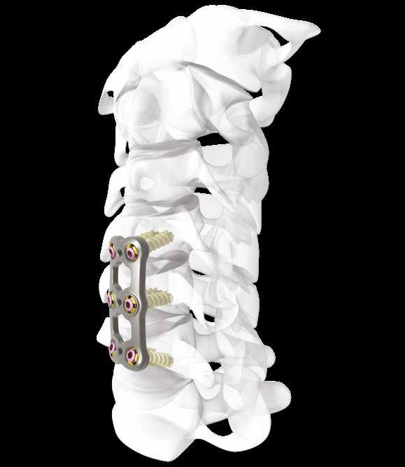
4 Mecta-C Plate Surgical Technique 1. INTRODUCTION The Mecta-C Anterior Cervical Plate System is designed to offer maximum biomechanical stability in situ and high flexibility in term of implants range selection and configurations. The Mecta-C Anterior Cervical Plate System devices are made of Titanium alloy (Ti-6Al-4V). The plates are prelordosed to match the natural curvature of the spine and are designed to cover up to four level configurations ranging from 20mm - 92mm in length. Also, constrained, semi-constrained or hybrid angle constructs may be built using Fixed or Variable angle bone screws system; provided with Self-Tapping and Self-Drilling options the bone screws are available in two diameters and several lengths. Fixed screw [no micro movements allowed] Variable screw [micro movements allowed] The screw configurations can be identified by their unique color-code: Fixed screws (fig.2): 4.0 mm Self Tapping (Gold & Silver) 4.0 mm Self Drilling (Blue & Silver) 4.5mm Self Tapping (Green & Silver) Overall, the different Mecta-C plates configurations bring beneficial advantages to meet different patients needs in tumor, trauma and degenerative as well as in deformity cases. 1.1 MECTA-C CERVICAL PLATES The Cervical Plates are provided in the following configurations (fig.1): 1, 2, 3 and 4-Level Sizes ranging from 20-92mm in length (end-to-end plate measure). 2. The fixed screw design is identified by the partial anodization (dual color) of the screw shank. NOTICE: For the fixed screw design the color of the Locking screw can be either violet or silver. Variable screws (fig.3): 4.0 mm Self Tapping (Full Gold) 4.0 mm Self Drilling (Full Blue) 4.5mm Self Tapping (Full Green) 1. L1 L2 L3 L BONE SCREWS The cervical bone screws are available in the following configurations: Primary screws: 4.0mm diameter 12mm 22mm length (1mm increment) Rescue screws: 4.5mm diameter12mm 22mm length (2mm increment) All the screws are polyaxial with the capability to convert into two configurations: Self-Tapping and Self-Drilling screws are identified with the following tip design (fig.4): 4. Self-Tapping Self-Drilling 4


5 Construct design The Mecta-C Plate screw design incorporates the function of an expansion head screw matched with an inner preassembled locking screw. The specific design of the preassembled locking screw determines the degree of interaction versus the flanges of the bone screw head defining its fixed of variable configuration. Constrained configuration - When the fixed screw is finally secured in place the locking screw expands against the flanges of the screw-head by locking the system within the hole plate. The combination of the Mecta-C plate with the fixed screws provide a construct with superior stability, which properties may be beneficial in tumor, trauma and degenerative applications Hybrid configuration - The hybrid construct configuration can be obtained by using a combination of fixed and variable screws within the end holes of the plate. 5. The use of this type of construct allows to reach a stable configuration capable of providing proper load sharing at the graft receptor side. Semi constrained configuration - When the variable screw is finally secured in place the Locking screw partially expands against the flanges of the screw-head by allowing slight toggling of the screw within the hole plate. A Variable construct allows optimal load sharing of the treated segments in degenerative cases, and may be especially beneficial in multi-level applications when major dynamic stabilization is requested. 8. In all the construct configurations above cited the bone screws can be positioned with the following trajectories: Cranial/Caudal screws: 20 distal/-8 proximal and 6 medial convergent/6 lateral divergent angle, approximately. Mid screws: ±10 distal/proximal and 6 medial convergent/6 lateral divergent angle, approximately WARNING In case of implantation of screws longer than 18mm, the screw length has to be verified by fluoroscopy prior to screw insertion; this is meant to prevent screw interference. 5
 degenerative disc disease (as defined by")
, 5) pseudarthrosis, and/or 6) failed previous fusions. This device system is intended for anterior cervical intervertebral body fusions only. 1.")
6 Mecta-C Plate Surgical Technique 1.3 INDICATIONS This system is intended for anterior interbody screw/plate fixation from C2 to T1. The system is indicated for use in the temporary stabilization of the anterior spine during the development of cervical spinal fusions in patients with: I) degenerative disc disease (as defined by neck pain of discogenic origin with degeneration of the disc confirmed by patient history and radiographic studies), 2) trauma (including fractures), 3) tumors, 4) deformity (defined as kyphosis, lordosis, or scoliosis), 5) pseudarthrosis, and/or 6) failed previous fusions. This device system is intended for anterior cervical intervertebral body fusions only. 1.4 CONTRAINDICATIONS This device is not approved for screw attachment to the posterior elements (pedicles) of the cervical, thoracic, or lumbar spine Contraindications include, but are not limited to: 1. Infection, local to the operative site. 2. Signs of local inflammation. 3. Fever or leukocytosis. 4. Morbid obesity. 5. Pregnancy. 6. Mental illness. 7. Any medical or surgical condition which would preclude the potential benefit of spinal implant surgery, such as the elevation of sedimentation rate unexplained by other diseases, elevation of white blood count (WBC), or a marked left shift in the WBC differential count. 8. Rapid joint disease, bone absorption, osteopenia, and/ or osteoporosis. Osteoporosis is a relative contraindication since this condition may limit the degree of obtainable correction, the amount of mechanical fixation, and/or the quality of the bone graft. 9. Suspected or documented metal allergy or intolerance. 10. Any case not needing a bone graft and fusion or where fracture healing is not required. 11. Any case requiring the mixing of metals from different components. 12. Any patient having inadequate tissue coverage over the operative site or where there is inadequate bone stock, bone quality, or anatomical definition. 13. Any case not described in the Indications. 14. Any patient unwilling to cooperate with the postoperative instructions. 15. Any time implant utilization would interfere with anatomical structures or expected physiological performance. 1.5 PRE-OPERATIVE PLANNING The review of MRI and/or CT based imaging to template and determine the type/size of the implants in order to match the patient s anatomy is a critical step in the preoperative planning before each surgery. 2. PATIENT POSITIONING SPINE EXPOSURE The patient is placed in the supine position with the head slightly extended and resting on an appropriate base. A shoulder bump may be needed to generate the desired amount of cervical lordosis. The arms are secured along the sides of the body. The image intensifier is positioned in such a way to enable adequate intra-operative anteroposterior and lateral imaging. A transverse incision is made along Langer s lines extending approximately from the sternocleidomastoid muscle to the midline. Correct location of the skin incision is accomplished either by using anatomic landmarks or by using image intensifier


 insertion the Mecta-C anterior cervical device can be combined with the Mecta-C plate system. 12. 3. IMPLANT SELECTION 3.")
7 The platysmal layer is then incised either horizontally in line with the incision (shown) or vertically at the discretion of the surgeon. Electrocautery is used to elevate the longus colli muscles. Medio-lateral retractors are placed underneath the longus muscles in order to protect the sympathetic chain. Mark the appropriate disc and perform a lateral X-ray to verify the appropriate level. 11. Incise the pretracheal fascia which allows for retraction of the midline structures. Perform blunt dissection using the index finger to expose the anterior cervical spine. 13. Then a Cranial/Caudal retractor can be placed to further optimize the visualization. The Mecta-C cervical Anterior Retractor/Distractor System can be used to provide optimal retraction/distraction maneuvers. OPTION After the cervical spine has been exposed and prepared perform the next steps (disc removal/decompression/cage insertion/corpectomy etc.) following the usual fashion in order to accommodate individual surgery needs. In case of disc replacement with cage(s) insertion the Mecta-C anterior cervical device can be combined with the Mecta-C plate system IMPLANT SELECTION 3.1 HANDLING OPTIONS & DRILL GUIDES To handle the Mecta-C Plate Trials as well as the Implants, different options are available, thus providing the maximum flexibility during the selection/plates and screws placement process. Cervical Plate Forceps The Cervical Plate Forceps can be utilized to hold the plate from the medial/lateral sides


 to support the plate during the placement and the drilling steps.")

8 Mecta-C Plate Surgical Technique Plate Holder The Plate Holder can be primarily utilized to provide superior stability to position the longer plates. To attach the implant to the Inserter, turn the thumb wheel to the unlock position and attach the implant. Turn the thumb wheel 90 into the lock position to firmly hold the Plate. medial/lateral hole(s) supporting the construct during the placement and the drilling steps. These guides are considered fully locked when the tip is flush with the plate. When using the Universal Plate Holder the guide is securely locked into the plate by applying light downward pressure on the handle. Single Hole and Double Hole Drilling Guide Insert the distal tip into the medial/lateral hole(s) to support the plate during the placement and the drilling steps. These guides are considered engaged when the tip is flush with the plate Handle Of The Plate Holder The handle of the plate holder can be fixed at different angle positions: 45 ; 60 ; 90 on both Sagittal and Transverse plane. 18. Universal Plate Holder When using the Universal Plate Holder the guide is securely locked into the plate by pulling back the handle after the insertion of the tip into the plate hole. 16. As alternative, the Single-hole as well as the Double-Hole Drilling Guide and the Universal Plate holder can be used to position the cervical plate in situ. The distal tip into the 8


9 3.2 TRIAL INSERTION Select a Trial Plate of the estimated length and place it on the vertebral body to determine the actual plate length. 19. NOTICE: if the guide cannot be released from the plate apply a slight pulling pressure on the trigger handle. Fork Drilling Guide In case of combination with the Mecta-C cervical cage implant(s) the Fork Drilling Guide can be used in order to provide self-centering during the drilling procedure. The Fork Drilling Guide perfectly fit with the several Mecta-C cervical implants providing a dedicated tool for the cervical cage/plate devices implantation. 21. If desired, hold the Trial Cervical Plate in place with the Temporary Fixation Pin. Using the Self-Retaining Screwdriver the pin can be inserted either in the central or in the medial/lateral holes to support the trial selection; in this latter case multiple sampling can be performed without remove the pin from the vertebral body CAUTION Remove the Temporary Fixation Pin after the Trial selection is completed. 9


10 Mecta-C Plate Surgical Technique 4. IMPLANT PLATE PREPARATION AND POSITIONING 4.1 IMPLANT SELECTION After the plate length has been determined with the Trial selection, choose the appropriate Mecta-C cervical Plate and ensure that the plate s lordosis fits with the patient s anatomy. OPTION Alternatively, seat one of the available drilling guides into plate hole and insert the Drill-bit with the desired length to determine the depth of perforation. NOTICE: the Mecta-C cervical plate is already provided with a lordotic curve; if required, a Cervical Plate Bender can be used to contour the plate in order to increase or decrease the lordotic curvature. 23. WARNING Contour the cervical Plate only when needed. In contouring the cervical plate apply gradual bending steps and avoid excessive changes of the plate s curvature BONE PREPARATION Place the selected Mecta-C cervical plate in the desired position onto the vertebral body and if desired, hold it in place with the Temporary Fixation Pin systems previously described. Insert the Self-centering Awl into the plate hole to perforate the outer cortex; the depth of perforation can be controlled with the scale located on the Self-centering Awl shaft. 26. NOTICE: the depth of perforation is determined by the selected screw length and it is based on the required bone purchase. The Cervical Depth Gauge can be used to check the canal depth and to help determining the length of the cervical screw. 24. NOTICE: the length of the awl perforation is limited to 12mm as the inferior screw length size. 10


11 assemble the Self-Retaining Screwdriver (fig.1): add the Retaining Sleeve (A) to the Screwdriver Main Body (B). A B 27. CAUTION The depth of perforation must be monitored by x-ray to avoid perforation of the posterior cortex. WARNING In case of sclerotic bone or any other reason that can cause high resistance during screw placement, bone preparation should be performed by using the provided tap. 29. The Self-Drilling/Self-Tapping screws can be inserted and fixed with the Self-Retaining Screwdriver specifically designed to easily align the screw and to avoid toggling. To couple the screw to the screwdriver-assembly retract the Retaining Sleeve backward and Insert the screwdriver tip into the screw head (fig.2a,b). CAUTION Carefully tap at the desired length, as indicated by the scale on the tap shaft. A B 30. Screw NOT engaged Then, slide the Retaining Sleeve forward until full snap is reached in order to engage the screw head (fig.3a); the alignment of the marking line positioned on the shaft with the Retaining Sleeve indicates the proper matching with the screw (fig.3b). 28. WARNING Bone preparation must be always performed both in primary and revision surgeries to prepare the correct hole trajectory and avoid screw mis-placement. 31. A Screw fully engaged B 4.3 PLATE POSITIONING WITH THE SELF- DRILLING/SELF-TAPPING SCREWS After the vertebral body has been prepared, the surgeon can plan for the cervical screw insertion. The length of the screw to be implanted is established in relation to the vertebral anatomy. Before starting to insert the screw, 11

; retract the Self Retaining Screwdriver-screw assembly as the insertion is fully accomplished. The appropriate screw length can be verified using the Screw/Cage Loading Station (fig.4c).")


12 Mecta-C Plate Surgical Technique OPTION To help coupling the bone screw to the Self Retaining Screwdriver use the Screw/Cage Loading Station. Insert the selected screw to the corresponding place in the rack depending on the length and the diameter. Holding the screw in place engage it to the Self-Retaining Screwdriver following the steps previously described (fig.4a,b); retract the Self Retaining Screwdriver-screw assembly as the insertion is fully accomplished. The appropriate screw length can be verified using the Screw/Cage Loading Station (fig.4c). OPTION If necessary, the Screw Remover can be used to drive the screw(s) through the Mecta-C plate hole(s). 4.4 SCREW LOCKING For the final locking of the pre-assembled screws, engage the Counter Torque to the Final Locking Screwdriver and tighten until a tactable sound indicates the final screw tightening has been achieved. A B C Once the screw is properly engaged with the Self-Retaining Screwdriver, insert the screw through the Mecta-C cervical plate hole until seated. Drill the remaining holes, measure and insert the remaining screws using the same technique. NOTICE: in order to achieve a correct coupling, proceed to insert the Final Screwdriver to the screw first (A); then slide the Counter Torque Sleeve to engage the bone screw (B). CAUTION When placing the screw, avoid to exert bending forces onto the Self Retaining screwdriver as these can result in screw and instrument damages. A B SCREW REMOVAL In case of bone screw repositioning the Screw Removal can be performed with three different procedures depending on the stage of screw fixation. 33. CAUTION As soon as the screw is seated into the Mecta-C plate hole, stop rotating as excessive tightening torque may result in unexpected failure. Procedure 1 - If the final locking procedure has not been accomplished, and the Self-Retaining Screwdriver cannot be utilised, the Screw Remover should be used. To start the screw removal, position the distal tip of the Screw Remover until seated into the Bone Screw. Slide the sleeve forward to constrain the Locking Screw head and remove the screw by turning counterclockwise while pulling back the Screwto-Screw Remover assembly. 12


13 36. Procedure 2 - When the final locking procedure is completed the Counter Torque Final Locking Screwdriver assembly has to be used to unscrew the pre-assembled locking screw. The Self-Retaining Screwdriver has to be then used to remove the bone screw. 38. Counter-clockwise direction NOTICE: the locking screw extractor can be used to remove the screw in case the purple locking screw has been previously inadvertently disassembled 37. Procedure 3 - If the recess of the pre-assembled Locking screw is damaged and the final tightening is completed the Locking Screw Extractor must be used. Insert the Locking Screw Extractor into the hex recess of the Locking Screw applying a slight pressure and turn it counter-clockwise to remove the screw. 13


14 Mecta-C Plate Surgical Technique 5. MODULAR RIGID SCREWDRIVER A further option to insert the screws is the Modular Rigid Screwdriver. The following paragraphs desribe the step to follow for a correct usage of the instrument. 5.1 BONE SCREW PREPARATION Start preparing the Mecta Plate bone screws for the insertion. Place the Self-Drilling / Self-Tapping Screws in the dedicated holes, located in the Loading Station Attach the Counter Torque to the Final Locking Screwdriver and pull it all the way back until mechanical stop. The correct assembly is reached when the Final Screwdriver tip appears as shown in the picture below. 43. Unscrew the inner Locking Screw by rotating the Final Locking Screwdriver counter-clockwise, while preventing bone screw rotation, and place it in the dedicated area in the loading station Insert the Final Screwdriver into the screw, slide the Counter Torque Sleeve to engage it and prepare to disassemble the Locking screw from the bone screw. 14


15 To couple the screw with the screwdriver, match the flanged outer sleeve with the bone screw and then slide the Inner Shaft through; to lock the screw, turn the Inner Shaft clockwise from the proximal knob until it reaches the mechanical stop. 45. WARNING Ensure the locking screws are placed in the correct locations; V identifies the location for the Variable Locking Screw and F identifies the location for the Fixed Locking Screw - do not mix these up MODULAR RIGID SCREW DRIVER PREPARATION 50. Before inserting the screw, assemble the Modular Rigid Screwdriver : insert the threaded inner shaft into the main body of the screwdriver until it reaches the mechanical stop CAUTION While assembling the bone screw to the Modular Rigid Screwdriver, do not over torque the Inner Shaft to avoid damaging the screw or the screwdriver interface


16 Mecta-C Plate Surgical Technique NOTICE: To attach the bone screw to the Modular Rigid Screwdriver use the Screw/Cage Loading Station. Insert the selected screw into the corresponding place in the rack depending on the length and diameter. NOTICE: The proximal knob of the inner shaft must be flush with the handle to ensure the screw is engaged The appropriate screw length can be verified using the Screw/Cage Loading Station. CAUTION When placing the screw, avoid to exert bending forces onto the Modular Rigid Screwdriver as this can results in screw and instrument damages. CAUTION When the screw is seated in the Mecta-C plate hole, stop rotating as over-tightening torque may result in an unexpected failure. CAUTION Be sure that the inner shaft is fully disengaged before removal of the Modular Rigid Screwdriver to avoid unexpected screw/screwdriver failure SCREW INSERTION Once the screw is properly engaged with the Modular Rigid Screwdriver, insert it through the Mecta-C cervical plate hole until seated, then properly remove the Inner Shaft. Drill the remaining holes, measure and insert the remaining screws using the same technique. OPTION If necessary, the Screw Remover can be used to drive the screw(s) through the Mecta-C plate hole(s). To complete the bone screw positioning, insert the corresponding locking screw using the Final Locking Screwdriver or the Locking Screw Holder, to achieve a temporary loading of the locking screw onto the bone screw. NOTICE: Use the screw holder to temporary fix the locking screw in the pre-assembled position. It cannot be used for final locking procedure
 would lead to the screw final locking.")
17 Fixed screws CAUTION Carefully inspect the locking screw insertion especially when using the Final Locking Screwdriver as its complete rotation (LOCKED Position) would lead to the screw final locking. A reasonable pre-final locking of the screw is achieved before the locking screw is flush with the bone screw upper head in the PRE ASSEMBLED position. The fixed screw design is identified by the partial anodization (dual color) of the screw shank. NOTICE: For the fixed screw design the color of the Locking screw can be either violet or silver. Variable screws 59. The variable screw design is identified by a single color of the screw shank. 57. Pre mounted Pre assembled Locked CAUTION Ensure the locking screw is coupled with the corresponding fixed or variable bone screw. Ensure the proper screw is selected. 5.4 SCREW LOCKING For the final locking follow the steps described in paragraph 4.4 SCREW LOCKING. 17
18 Mecta-C Plate Surgical Technique 6. IMPLANTS NOMENCLATURE 6.1 STERILE PACKAGE Anterior Cervical Plates REFERENCE DESCRIPTION / FIGURE LEVEL SIZE LENGTH (mm) L L L L
19 Variable Self-Drilling and Self-Tapping Screws I VARIABLE SELF-DRILLING SCREW VARIABLE SELF-TAPPING SCREW DESCRIPTION Reference Size Ø mm Length (mm) Q.ty Reference Fixed Self-Drilling and Self-Tapping Screws I FIXED SELF-DRILLING SCREW* FIXED SELF-TAPPING SCREW* DESCRIPTION Reference Size Ø mm Length (mm) Q.ty Reference I Additional sizes available on demand *The Locking screw can be either violet or silver 19
20 Mecta-C Plate Surgical Technique Variable and fixed Self-Tapping Screws I VARIABLE SELF-TAPPING SCREW FIXED SELF-TAPPING SCREW* DESCRIPTION Reference Size Ø mm Length (mm) Q.ty Reference I Additional sizes available on demand *The Locking screw can be either violet or silver 20
21 Part numbers subject to change. NOTE FOR STERILIZATION The instruments are not sterile upon delivery. Instruments must be cleaned before use and sterilized in an autoclave respecting the US regulations, directives where applicable, and following the manufactures instructions for use of the autoclave. For detailed instructions please refer to the document Recommendations for cleaning decontamination and sterilization of Medacta International reusable orthopaedic devices available at 21
22 Mecta-C Plate Surgical Technique NOTES 22
23 23
24 Medacta International SA Strada Regina Castel San Pietro - Switzerland Phone Fax info@medacta.ch Find your local dealer at: medacta.com/locations All trademarks and registered trademarks are the property of their respective owners. This document is intended for the US market. Mecta-C Plate Surgical Technique ref: 99.44CP.12US rev. 04 Last update: July
UNIQUE PATIENTS SPECIFIC INDICATIONS IN ONE SYSTEM. Surgical Technique
 UNIQUE PATIENTS SPECIFIC INDICATIONS IN ONE SYSTEM Surgical Technique Joint Spine Sports Med Mecta-C Plate Surgical Technique 2 INDEX 1. INTRODUCTION 4 1.1 Mecta-C Cervical Plates 4 1.2 Bone Screws 4 1.3
Reflex TM Surgical Technique. Anterior Cervical Plate
 Reflex TM Surgical Technique Anterior Cervical Plate Surgical Technique Acknowledgement: Stryker Spine extends their thanks to the following surgeons for their participation in the development of the Reflex
VECTRA SURGICAL TECHNIQUE. Anterior cervical plate system. This publication is not intended for distribution in the USA.
 VECTRA Anterior cervical plate system This publication is not intended for distribution in the USA. SURGICAL TECHNIQUE Image intensifier control This description alone does not provide sufficient background
VECTRA. SURGICAL TECHNIQUE. Anterior cervical plate system. This publication is not intended for distribution in the USA.
 VECTRA. Anterior cervical plate system. This publication is not intended for distribution in the USA. SURGICAL TECHNIQUE Contents Indications and contraindications Implants Vario Case Instruments Surgical
BLACKBIRD Spinal System
 BLACKBIRD Spinal System Cervical-Thoracic Spinal Fixation System The ChoiceSpine BLACKBIRD Cervical-Thoracic Spinal Fixation System is a comprehensive system for posterior fixation of the cervical and upper
MaxAn Anterior Cervical Plate System
 Surgical Technique MaxAn Anterior Cervical Plate System Designed to Help Minimize the Potential for Adjacent Level Ossification Allows for screw placement up to 30 cephalad on the superior end of the plate
Vectra, Vectra-T and Vectra-One. Anterior cervical plating for spinal fusion.
 Vectra, Vectra-T and Vectra-One. Anterior cervical plating for spinal fusion. Technique Guide Instruments and implants approved by the AO Foundation Table of Contents Introduction Vectra, Vectra-T and
Optima ZS Spinal Fixation System
 Surgical Technique Optima ZS Spinal Fixation System The low-profile, in-line, polyaxial pedicle screw system. Optima ZS Surgical Technique 1 Optima ZS Spinal Fixation System The Optima ZS Spinal Fixation
ACLP Anterior Cervical Locking Plate System TECHNIQUE GUIDE
 ACLP Anterior Cervical Locking Plate System TECHNIQUE GUIDE Instruments and implants approved by the AO Foundation ACLP Anterior Cervical Locking Plate System The ACLP System is designed to reduce the
ACCS Anterior Cervical Compression System TECHNIQUE GUIDE
 ACCS Anterior Cervical Compression System TECHNIQUE GUIDE Original Instruments and Implants of the Association for the Study of Internal Fixation AO ASIF ACCS Anterior Cervical Compression System The Anterior
ACP 1. Anterior Cervical Plating System. Surgical Technique
 ACP 1 Anterior Cervical Plating System Surgical Technique Table of Contents System Overview.... 3 Patient Positioning and Exposure.... 5 Implant Selection and Preparation... 7 Screw Hole Preparation...
Gibralt. Occipito-Cervico Thoracc System. Operative Technique
 Gibralt Occipito-Cervico Thoracc System Operative Technique TABLE OF CONTENTS GIBRALT...1 OPERATIVE TECHNIQUE OVERVIEW...2 HOOK PLACEMENT...2 SCREW PLACEMENT...2 DETAILED OPERATIVE TECHNIQUE...4 PLACEMENT
Nakoma-SL Anterior Cervical Plating System Surgical Technique
 Anterior Cervical Plating System Surgical Technique Table of Contents Indications for Use................................1 Device Description............................... 1 Nakoma-SL Implant Key Features.........................2
URS Degen. Top loading pedicle screw system for posterior stabilization.
 URS Degen. Top loading pedicle screw system for posterior stabilization. Technique Guide This publication is not intended for distribution in the USA. Table of Contents Introduction URS Degen 2 AO Principles
Aviator Anterior Cervical Plating System Surgical Technique
 Aviator Anterior Cervical Plating System Surgical Technique Table of Contents System Overview...3-4 Patient Positioning and Exposure...5 Implant Selection and Preparation.... 6-7 Screw Hole Preparation....
Anterior Cervical Plate SURGICAL TECHNIQUE GUIDE. Surgeon Driven Innovation
 Anterior Cervical Plate SURGICAL TECHNIQUE GUIDE Surgeon Driven Innovation 1 The Snowmass Anterior Cervical Plate System is intended for the surgical treatment and correction of traumatic and pathologic
Technique Guide. Occipito-Cervical Fusion System. Implants and instruments designed to optimize fixation to the occiput.
 Technique Guide Occipito-Cervical Fusion System. Implants and instruments designed to optimize fixation to the occiput. Table of Contents Introduction Overview 2 AO ASIF Principles 4 Indications and Contraindications
PAC PLATE A N T E R I O R C E RV I CA L P L AT E SYST E M S U R G I C A L T E C H N I Q U E
 PAC PLATE A N T E R I O R C E RV I CA L P L AT E SYST E M S U R G I C A L T E C H N I Q U E PAC PLATE ANTERIOR CERVICAL PLATE SYSTEM Table of Contents INTRODUCTION System Overview... 1 SURGICAL TECHNIQUE
ThinLine Anterior Cervical Plate
 ThinLine Anterior Cervical Plate Surgical Technique Solutions by the people of Zimmer Spine. zimmerspine.com Designed for those times when less means more. From the people of Zimmer Spine. ThinLine is
Pangea Degenerative Spine System. Top Loading Preassembled Pedicle Screw System for Posterior Stabilization of the Thoracolumbar Spine.
 Technique Guide Pangea Degenerative Spine System. Top Loading Preassembled Pedicle Screw System for Posterior Stabilization of the Thoracolumbar Spine. Contents Introduction AO ASIF Principles 4 Indications
Aesculap Spine S 4 Spinal System. Instrumentation Guide
 Aesculap Spine S 4 Spinal System Instrumentation Guide S 4 Spinal System S 4 From initial conception, the S 4 Spinal System was developed to meet the spine surgeon s need for an extremely low profile and
Technique Guide. Synapse System. An enhanced set of instruments and implants for posterior stabilization of the cervical and upper thoracic spine.
 Technique Guide Synapse System. An enhanced set of instruments and implants for posterior stabilization of the cervical and upper thoracic spine. Table of Contents Introduction Synapse System 2 AO Principles
ThinLine. Surgical Technique. Anterior Cervical Plate. zimmerspine.com
 ThinLine Anterior Cervical Plate Surgical Technique zimmerspine.com Designed for those times when less means more. From the people of Zimmer Spine. The ThinLine System is the lowest profile plate in the
Escalate TM. Laminoplasty System Surgical Technique. Expandable Laminoplasty Plate Streamlined Procedure
 Expandable Laminoplasty Plate Streamlined Procedure Table of Contents System Overview.... 3-4 Surgical Procedure....5-12 Expandable Laminoplasty Plate Technique....6-11 Base Laminoplasty Plate Technique....
Occipito-Cervical Fusion System. Implants and instruments designed to optimize fixation to the occiput.
 Occipito-Cervical Fusion System. Implants and instruments designed to optimize fixation to the occiput. Technique Guide This publication is not intended for distribution in the USA. Instruments and implants
Surgical Technique. Anterior Cervical Plating System
 Reflex Hybrid Surgical Technique Anterior Cervical Plating System Table of Contents Introduction 2 System Overview 3 Patient Positioning and Exposure 6 Implant Selection and Preparation 6 Bone Screw Hole
Interlagos Retractor System Surgical Technique
 Interlagos Retractor System Surgical Technique TABLE OF CONTENTS Instructions for Use Design Rationale Surgical Technique 1. Pre-Operative Preparation 2. Pedicle Preparation 3. Primary Retraction 4. Secondary
SlimLine Anterior Cervical Plate
 SlimLine Anterior Cervical Plate Surgical Technique Solutions by the people of Zimmer Spine. zimmerspine.com Efficient Design. Proven Results. From the people of Zimmer Spine. SlimLine is backed by an
Aviator Anterior Cervical Plating System System Overview. Visual and tactile confirmation Increased Angulation Simplified instrumentation
 Aviator Anterior Cervical Plating System System Overview Visual and tactile confirmation Increased Angulation Simplified instrumentation The Aviator anterior cervical plating system offers a unique double
Synapse System. An enhanced set of instruments and implants for posterior stabilization of the upper spine.
 Synapse System. An enhanced set of instruments and implants for posterior stabilization of the upper spine. Technique Guide 100º Instruments and implants approved by the AO Foundation Table of Contents
OCCIPITO-CERVICAL FUSION SYSTEM Implants and instruments designed to optimize fixation to the occiput
 OCCIPITO-CERVICAL FUSION SYSTEM Implants and instruments designed to optimize fixation to the occiput Instruments and implants approved by the AO Foundation. This publication is not intended for distribution
Vertebral Body Derotation System Guide and Ordering Information
 Vertebral Body Derotation System Guide and Ordering Information Introduction DePuy Spine continues to support the goal of providing solutions to surgeon challenges when treating spinal disorders. Collaborating
CSLP Variable Angle. For Use with the Cervical Spine Locking Plate System TECHNIQUE GUIDE. Self-drilling Screw. Variable Screw Angulation
 CSLP Variable Angle For Use with the Cervical Spine Locking Plate System TECHNIQUE GUIDE Self-drilling Screw Variable Screw Angulation Original Instruments and Implants of the Association for the Study
Reflex Hybrid System Overview
 Spine Reflex Hybrid System Overview Anterior Cervical Plating System Introduction The Reflex Hybrid ACP System offers a low-profile anterior cervical plate along with a selection of bone screw types to
D. Greg Anderson, MD Thomas Jefferson University Hospital Philadelphia, PA
 Surgical Technique D E S I G N I N G S U R G E O N S D. Greg Anderson, MD Thomas Jefferson University Hospital Philadelphia, PA Robert Heary, MD University of Medicine and Dentistry of New Jersey Newark,
Technique Guide. Synapse System. An enhanced set of implants and instruments for posterior stabilization of the cervical and upper thoracic spine.
 Technique Guide Synapse System. An enhanced set of implants and instruments for posterior stabilization of the cervical and upper thoracic spine. Image intensifier control Warning This description alone
Surgical Technique. and Ordering Information
 Surgical Technique and Ordering Information INTRODUCTION CONTENTS The SKYLINE Anterior Cervical Plate provides a versatile system of implants and instruments to accommodate the needs and individual preferences
Top Loading Pedicle Screw and Hook System for Posterior Stabilization. URS System. Surgical Technique
 Top Loading Pedicle Screw and Hook System for Posterior Stabilization URS System Surgical Technique Image intensifier control This description alone does not provide sufficient background for direct use
SYnaPSe oct SYSteM. An enhanced set of instruments and implants for posterior stabilization of the upper spine
 SYnaPSe oct SYSteM An enhanced set of instruments and implants for posterior stabilization of the upper spine SurgIcal technique Table of Contents Introduction SYNAPSE OCT System 2 AO Principles 5 Indications
Cervical Solutions. Lineum OCT. Spine System. Surgical Technique Guide
 Cervical Solutions Lineum OCT Spine System Surgical Technique Guide 2 Lineum OCT Spine System Surgical Technique Guide Designed to encourage optimal screw placement and procedural efficiency Lineum OCT
OPERATIVE TECHNIQUE CENTURION POSTERIOR OCCIPITAL CERVICO-THORACIC (POCT) SYSTEM
 SYSTEM") OPERATIVE TECHNIQUE CENTURION POSTERIOR OCCIPITAL CERVICO-THORACIC (POCT) SYSTEM TABLE OF CONTENTS Introduction 2 System Overview 3 Cervical Operative Technique 4 Thoracic Operative Technique 10 Thoracic
OPERATIVE TECHNIQUE CENTURION POSTERIOR OCCIPITAL CERVICO-THORACIC (POCT) SYSTEM TABLE OF CONTENTS Introduction 2 System Overview 3 Cervical Operative Technique 4 Thoracic Operative Technique 10 Thoracic
Universal Humeral Nail
 990210009 INDEX Indications Preoperative Planning Patient Position Surgical Technique - Step 1 Open Humerus - Step 2 Calibrate The Nail - Step 3 Insert Nail - Step 4 Proximal Locking - Step 5 Assemble
SURGICAL TECHNIQUE GUIDE
 SURGICAL TECHNIQUE GUIDE DANGER indicates an imminently hazardous situation which, if not avoided, will result in death or serious injury. WARNING indicates a potentially hazardous situation which, if
Thoracolumbar Solutions. Vitality Spinal Fixation System. Surgical Technique Guide
 Thoracolumbar Solutions Vitality Spinal Fixation System Surgical Technique Guide Vitality Spinal System Surgical Technique Vitality Spinal System Surgical Technique Description, Indications and Contraindications...
Technique Guide. 2.4/2.7 mm Locking Tarsal Plates. Talus Plate, Navicular Plate and Cuboid Plate.
 Technique Guide 2.4/2.7 mm Locking Tarsal Plates. Talus Plate, Navicular Plate and Cuboid Plate. Table of Contents Introduction 2.4/2.7 mm Locking Tarsal Plates 2 AO Principles 4 Indications 5 Clinical
OPERATIVE TECHNIQUE RIVAL REDUCE FRACTURE PLATING SYSTEM. foot & ankle trauma procedures
 OPERATIVE TECHNIQUE RIVAL REDUCE FRACTURE PLATING SYSTEM foot & ankle trauma procedures INTRODUCTION 3 SYSTEM DESCRIPTION 3 TECHNICAL DETAILS 4 SALES AND MARKETING CONFIGURATION 5 OPERATIVE TECHNIQUE 7
Lineum OCT Spine System
 Surgical Technique Lineum OCT Spine System Designed to Encourage Optimal Screw Placement and Procedural Efficiency Game Changing Translation Screw 3.0mm of medial/lateral translation encourages optimal
A M E D S MART SOLUTIONS FAMILY MEMBER
 A M E D S MART SOLUTIONS FAMILY MEMBER Based in the United Kingdom, Medsmart Solutions is a dynamic 100% British owned company which is dedicated to the manufacture and supply of an extensive range of
Surgical Technique. Deformity - Degenerative. Interbody Fusion. Tumour - Trauma. Cervical. Emerging Technology
 Surgical Technique Deformity - Degenerative Interbody Fusion Tumour - Trauma Cervical Emerging Technology MONARCH SPINE SYSTEM Contents Introduction & Philosophy 2 Surgical Technique Monarch Bolts with
Occipito-Cervical Fusion System
 Implants and Instruments designed to enhance Fixation to the Occiput Occipito-Cervical Fusion System Surgical Technique Image intensifier control This description alone does not provide sufficient background
Surgical Technique. Customer Service:
 Patent Pending CAUTION: Federal Law (USA) restricts this device to sale by or on the order of a physician. Notes This page is blank INDICATIONS FOR USE The Extremity Medical Hallu X Intramedullary Fusion
OPERATIVE TECHNIQUE RIVAL VIEW PLATING SYSTEM. foot & ankle reconstruction procedures
 OPERATIVE TECHNIQUE RIVAL VIEW PLATING SYSTEM foot & ankle reconstruction procedures INTRODUCTION 3 SYSTEM DESCRIPTION 3 TECHNICAL DETAILS 4 SALES AND MARKETING CONFIGURATION 5 OPERATIVE TECHNIQUE 7 OPERATIVE
Integra. Capture Screw System SURGICAL TECHNIQUE
 Integra Capture Screw System SURGICAL TECHNIQUE Table of Contents Indications... 2 Contraindications... 2 System Description... 2 System Features... 2 Cannulated Low-Profile Screws (AC-Series) Overview...
VBOSS Surgical Technique
 VBOSS Surgical Technique 1 2 CONTENT 1. System Description 4 1.1 Implants 4 1.2 Instruments 6 2. Indications 11 3. Patient Position 11 4. Surgical Approach 12 4.1 Choice of adequate Parallel Distractor
Surgical Technique 1
 Surgical Technique 1 D-RAD SMART PACK Single-Use Volar Distal Radius Plating System Surgical Technique Table of Contents Indications... 3 Contraindications... 3 D-RAD SMART PACK product overview... 4 Instrumentation...
MaxTorque. surgical technique. Cannulated Screw System. Foot & Ankle. OrthoHelix Technology
 MaxTorque Cannulated Screw System OrthoHelix Technology surgical technique Foot & Ankle 2 M A X T O R Q U E C A N N U L A T E D S C R E W S Y S T E M Table of Contents Advantages 3 Indications 4 Contraindications
Surgical Technique ANAX TM OCT. Spinal System
 Surgical Technique ANAX TM OCT Spinal System Product Overview Occipital plate Medial occipital plate (Small, Medium, Large) Lateral occipital plate (Small, Medium, Large) Cortical screw (D4.5mm), Rescue
OPERATIVE TECHNIQUE RIVAL BITE HEADED CANNULATED AND HEADLESS COMPRESSION SCREWS. foot & ankle applications
 OPERATIVE TECHNIQUE RIVAL BITE HEADED CANNULATED AND HEADLESS COMPRESSION SCREWS foot & ankle applications INTRODUCTION 3 SYSTEM DESCRIPTION 3 TECHNICAL DETAILS 4 SALES AND MARKETING CONFIGURATION 6 OPERATIVE
V2F Anterior Fixation System
 TM V2F Anterior Fixation System Surgical Technique Solutions by the people of Zimmer Spine. zimmerspine.com Traditional approach. New Technique. From the people of Zimmer Spine. The V2F Anterior Fixation
VariAx DistalFibula. Foot & Ankle. Locking Plate System. Operative Technique
 VariAx DistalFibula Locking Plate System Operative Technique Foot & Ankle Distal Fibula Fracture Repair Polyaxial Locking Technology Low Profile Design VariAx 2 Color Coded Screws and Instruments VariAx
VBOSS. Surgical Technique. Vertebral Body Support System
 VBOSS Surgical Technique Vertebral Body Support System 1. System Description 1.1 Implants...3 1.2 Instruments...4 2. Indications...8 3. Patient Position...8 4. Surgical Approach 4.1 Choice of adequate
Technique Guide. 4.5 mm Cannulated Screws. Part of the Synthes Cannulated Screw System.
 Technique Guide 4.5 mm Cannulated Screws. Part of the Synthes Cannulated Screw System. TableofContents Introduction 4.5 mm Cannulated Screws 2 AO Principles 3 Indications 4 Surgical Technique Surgical
SYNAPSE SYSTEM An enhanced set of implants and instruments for posterior stabilization of the cervical and upper thoracic spine
 SYNAPSE SYSTEM An enhanced set of implants and instruments for posterior stabilization of the cervical and upper thoracic spine Instruments and implants approved by the AO Foundation. This publication
Technique Guide. 7.0 mm Cannulated Screws. Part of the Synthes Cannulated Screw System.
 Technique Guide 7.0 mm Cannulated Screws. Part of the Synthes Cannulated Screw System. Table of Contents Introduction 7.0 mm Cannulated Screws 2 AO Principles 3 Indications 4 Surgical Technique Surgical
Digital Compression Screw
 Digital Compression Screw Surgical Technique Contents Product The BioPro Digital Compression Screw is a stainless steel lag screw designed for digital fusions. Table of contents Indications & Contraindications
Technique Guide. Modular Sternal Cable System. Flexibility and strength in sternal closure and repair.
 Technique Guide Modular Sternal Cable System. Flexibility and strength in sternal closure and repair. Table of Contents Introduction Overview 2 Indications and Contraindications 3 Surgical Technique A.
OsteoBridge IKA Intramedullary Knee Arthrodesis Fixation System. From the «BioBall Company» OsteoBridge Family
 From the «BioBall Company» OsteoBridge Family OsteoBridge IKA Intramedullary Knee Arthrodesis Fixation System The modular system for the fixation of the knee joint 01. OsteoBridge IKA The OsteoBridge IKA
CETRA ANTERIOR CERVICAL PLATE
 CETRA TM ANTERIOR CERVICAL PLATE The CETRA Anterior Cervical Plate System offers a low profile titanium alloy plate with an intuitive locking mechanism, large graft windows, a high degree of screw angulation
VariAxFibula. Fibula Fractures. Locking Plate System. Operative Technique
 Foot and Ankle VariAxFibula Locking Plate System Operative Technique Fibula Fractures Distal Fibula Fracture Repair Polyaxial Locking Technology Low Profile Design VariAx Fibula Locking Plate System Contributing
Instructions for Use. LCP Locking Compression Plate. Combine without Compromise.
 Instructions for Use LCP Locking Compression Plate. Combine without Compromise. Table of Contents LCP: Combine without Compromise 2 AO ASIF Principles of Osteosynthesis 4 Indications and Contraindications
MEDIALMAX System SURGICAL TECHNIQUE
 MAXLOCK EXTREME MEDIALMAX System SURGICAL TECHNIQUE Contents The MEDIALMAX Advantage Design Feature Various flex options POCKETLOCK Technology Anatomic design Advantage Provides the surgeon with multiple
VariAx Fibula Locking Plate System
 VariAx Fibula Locking Plate System Operative Technique Distal Fibula Fracture Repair Polyaxial Locking Technology Low Profile Design 1 Contributing Surgeon: Bradley R. Merk, MD Associate Professor of Orthopaedic
Integra. Stainless Headed Compression Screw System SURGICAL TECHNIQUE
 Integra Stainless Headed Compression Screw System SURGICAL TECHNIQUE Table of Contents Design Rationale...2 Indications...2 Contraindications...2 Surgical Technique Step 1: Inserting Guide Wire... 3 Step
ISO Plate SURGICAL TECHNIQUE
 MINI MAXLOCK EXTREME ISO Plate SURGICAL TECHNIQUE Contents Table of Contents Key Design Features 2 Surgical Technique 3 Implants and Instruments 8 Key Design Features The MINI MAXLOCK EXTREME ISO (Intraosseous
DISTAL RADIUS PLATES 3.5 mm / ANGULARLY STABLE. Distal radius plates 3,5 mm / angularly stable. Locking bone screws. Cortical bone screw
 SURGICAL NÁSTROJE TECHNIQUE PRO ARTROSKOPII DISTAL INSTRUMENTS RADIUS PLATES FOR ARTHROSCOPY 3.5 mm / ANGULARLY STABLE Distal radius plates 3.5 mm / angularly stable Indication The plates are used for
REXIOUS SPINAL SYSTEM
 REXIOUS SPINAL SYSTEM SURGICAL TECHNIQUE www.diomedical.com. Site Preparation. Screw Insertion 3. Rod Preparation and Insertion 4. Rod Instruction 5. Set screw Insertion 6. Compression, Distraction & Rotation
POLYAXIAL SPINE SYSTEM
 S U R G I C A L T E C H N I Q U E En POLYAXIAL SPINE SYSTEM S C O L I O S I S INSTRUMENTATION A02240010 Pedicle hook starter A02240020 Laminar and transverse process hook starter A02240030 Compressor forceps
Fibula Plating System
 ANATOMIC LOCKED PLATING SYSTEM Fibula Plating System Securing optimal fixation through versatile locked and compression plating technology Contents Surgeon Design Team 2 Introduction 3 Anatomic Fibula
3.5 mm Cannulated Screw Technique Guide
 3.5 mm Cannulated Screw Technique Guide An Integral Part of the SYNTHES Cannulated Screw System Original Instruments and Implants of the Association for the Study of Internal Fixation AO ASIF The 3.5 mm
Operative Technique Distal Fibula Fracture Repair Polyaxial Locking Technology Low Profile Design
 VariAx Fibula Locking Plate System Operative Technique Distal Fibula Fracture Repair Polyaxial Locking Technology Low Profile Design Contributing Surgeon: Bradley R. Merk, MD Associate Professor of Orthopaedic
VLP FOOT Variable Angle Locked Plating System
 Surgical Technique VLP FOOT Variable Angle Locked Plating System Surgical Technique Table of Contents Product overview Implant selection...2 Introduction...3 System overview...4 Indications...4 Design
LCP Pilon Plate 2.7/3.5
 Surgical Technique LCP Locking Compression Plate Original Instruments and Implants of the Association for the Study of Internal Fixation AO/ASIF Table of contents Indications 3 Implants 4 Instruments 5
Integra. Tibio Talo Calcaneus Plate SURGICAL TECHNIQUE
 Integra Tibio Talo Calcaneus Plate SURGICAL TECHNIQUE Table of Contents Indications...02 Contraindications...02 Description...02 Surgical Technique...03 Step 1: Articular Surfaces Preparation...03 Step
SURGICAL TECHNIQUE. SpineTune THORACO-LUMBAR POSTERIOR OSTEOSYNTHESIS SYSTEM
 SURGICAL TECHNIQUE SpineTune TM TL THORACO-LUMBAR POSTERIOR OSTEOSYNTHESIS SYSTEM SURGICAL TECHNIQUE SpineTune TM TL Table of Contents page Step 1 - Site preparation.......................................................................................
Orthopedic Bone Nail System Universal Humeral Nail
 Orthopedic Bone Nail System Universal Humeral Nail Surgical Technique Manual Note: The surgical procedures should be performed under the guidance of qualified skilled orthopedic surgeons, and this surgical
Treace Medical Concepts Plating System
 Treace Medical Concepts Plating System Multiplanar Fixation System Surgical Technique Lapidus and 1 st MTP Fusion Lapidus Fusion Surgical Approach 1. Perform a longitudinal incision dorsally over the 1
TwinFix Surgical Protocol. 3.2mm Cannulated Compression Screw System
 TwinFix Surgical Protocol Compression Screw System TwinFix Compression Screw System Indications for Use: The Stryker TwinFix Interfragmentary Compression Screw System is intended to be used for fractures
S U R G I C A L T E C H N I Q U E TRAUMA & EXTREMITIES GROUP
 S U R G I C A L T E C H N I Q U E TRAUMA & EXTREMITIES GROUP TABLE OF CONTENTS ATN NAIL SYSTEM DESIGN RATIONALE INDICATIONS/CONTRAINDICATIONS PREOPERATIVE PLANNING AND PATIENT POSITIONING NAIL INSERTION
Zimmer Natural Nail System
 Zimmer Natural Nail System Cephalomedullary Small Nail Surgical Technique Table of Contents Product Overview... 2 Implant Overview... 2 Indications... 3 Contraindications... 3 Surgical Technique... 4 Preoperative
POLYAXIAL SPINE SYSTEM SURGICAL TECHNIQUE
 POLYAXIAL SPINE SYSTEM SURGICAL TECHNIQUE P O L Y A X I A L S P I N E S Y S T E M POLYAXIALITY STABILITY EFFICIENCY All the implants offer the Polyaxiality, including Hooks, Claws, Sacral Plates and of
SURGICAL TECHNIQUE. C-Plate ANTERIOR CERVICAL PLATE
 SURGICAL TECHNIQUE C-Plate ANTERIOR CERVICAL PLATE SURGICAL TECHNIQUE C-Plate Table of contents page Step 1 - Disc location and vertebral space preparation........................................ 3 Step
Peanut Growth Control Plating System. Surgical Technique
 Peanut Growth Control Plating System Surgical Technique 1 Peanut Growth Control Plating System Table of Contents System Design Features... 2 Instrument Tray... 5 Implant Caddy... 6 Surgical Technique...
OPERATIVE TECHNIQUE COVER IMAGE OPTIONAL (DETAIL) IMAGE FIREBIRD NXG. spinal fixation system
 IMAGE FIREBIRD NXG. spinal fixation system") OPERATIVE TECHNIQUE COVER IMAGE OPTIONAL (DETAIL) IMAGE FIREBIRD NXG spinal fixation system TABLE OF CONTENTS Introduction 1 Operative Technique 2 Reduction Body Technique 18 Implants and Instruments 24
OPERATIVE TECHNIQUE COVER IMAGE OPTIONAL (DETAIL) IMAGE FIREBIRD NXG spinal fixation system TABLE OF CONTENTS Introduction 1 Operative Technique 2 Reduction Body Technique 18 Implants and Instruments 24
HERO. Cervicale plate system
 HERO Cervicale plate system System The HERO anterior cervical plate system serves to stabilise the cervical spine following a ventral fusion. Thanks to its intelligent set of instruments, HERO is a highly
Zimmer Natural Nail System
 Zimmer Natural Nail System Cephalomedullary Nail Surgical Technique Compact Case - Short Nails Only STANDARD Zimmer Natural Nail System Cephalomedullary Nail Surgical Technique - Standard 1 Zimmer Natural
Omega 3 System Compression Hip Screw
 Omega 3 System Compression Hip Screw Hip Fracture Axially Stable Locking Option Contents Omega3 Compression Hip Screw Introduction 4 Potential Features & Benefits 5 Relative Indications & Contraindications
6.5 mm and 7.3 mm Cannulated Screws Technique Guide
 6.5 mm and 7.3 mm Cannulated Screws Technique Guide An Integral Part of the SYNTHES Cannulated Screw System Original Instruments and Implants of the Association for the Study of Internal Fixation AO ASIF
Zimmer Natural Nail System
 Zimmer Natural Nail System Cephalomedullary Nail Surgical Technique Compact Case- Short Nails Only SMALL Zimmer Natural Nail System Cephalomedullary Nail Technique - Small 1 Zimmer Natural Nail System
MTP Set SURGICAL TECHNIQUE
 MINI MAXLOCK EXTREME MTP Set SURGICAL TECHNIQUE Contents Table of Contents Key Design Features 3 Surgical Technique Standard MTP Plate 4 MTP Plate with POCKETLOCK Technology 10 Implants and Instruments
Zimmer Natural Nail System. Cephalomedullary Nail Surgical Technique SMALL
 Zimmer Natural Nail System Cephalomedullary Nail Surgical Technique SMALL Zimmer Natural Nail System Cephalomedullary Nail Technique - Small 1 Zimmer Natural Nail System Cephalomedullary Nail Surgical