Escalate TM. Laminoplasty System Surgical Technique. Expandable Laminoplasty Plate Streamlined Procedure
|
|
|
- Kevin Hancock
- 6 years ago
- Views:
Transcription
1 Expandable Laminoplasty Plate Streamlined Procedure
2 Table of Contents System Overview Surgical Procedure Expandable Laminoplasty Plate Technique Base Laminoplasty Plate Technique Implant Removal Implants Instruments Product Information


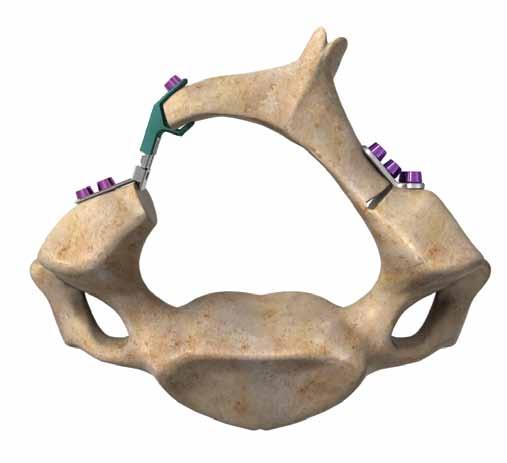
3 System Overview The Escalate System is a comprehensive set of implants and instruments designed for a systematic approach to cervical laminoplasty procedures. The system features an Expandable Laminoplasty Plate, a Base Laminoplasty Plate, Bone Screws for fixation, and a set of instruments to assist in implantation and removal of the device, if necessary. Expandable Laminoplasty Plate The open end of the Expandable Laminoplasty Plate attaches to the open lamina while the straight end of the plate corresponds to the lateral mass. The plate can then be expanded in situ (from 8-12mm in 2mm increments). This design allows for a single implant to be used in varying patient situations, obviating the need for trialing. The plate is made of titanium alloy (Ti6Al4V), is 5mm wide, and features a laminar mouth (5.4mm wide) designed to capture the lamina during plate expansion and screw insertion. Expandable Laminoplasty Plate ( ) 0.6mm 5.4mm 2mm 4mm 0.6mm 8mm 0.75mm 10mm 12mm Fully Closed Partially Open Fully Open 3

. The system also contains a 2.")
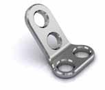
4 Base Laminoplasty Plate The Base Laminoplasty Plate can be used to reinforce an unstable hinge after a laminoplasty procedure. It can be attached directly to the lamina above and to the lateral mass beneath the hinge. Base Laminoplasty Plate ( ) The Base Laminoplasty Plate features two screw holes which can be used to secure the plate to the laminar hinge and two holes which can be used to attach the plate to the lateral mass. Bone Screws The Escalate features a 2.0mm diameter self-drilling screw in lengths of 4-10mm (magenta color). The system also contains a 2.4mm diameter selftapping rescue screw in lengths of 4-10mm (purple color). The screws feature a square drive for rigid attachment to the self-retaining screwdriver. Square Drive of Screw Ø2.0mm Self-Drilling Screw Ø2.4mm Self-Tapping Screw 4

. Care must be taken not to remove an excessive amount of bone when creating the trough opposite the open side as this may result in an unstable hinge.")

5 Surgical Procedure Patient Positioning and Exposure The patient is placed in the prone position with the head and neck adequately secured. A midline incision is made sub-periosteally, exposing the spinous processes and lamina at the desired levels. To perform an open-door laminoplasty procedure, create a vertical trough completely through the lamina on one side of the posterior arch (the open side ) and a unicortical trough on the contralateral side (the hinge ). Care must be taken not to remove an excessive amount of bone when creating the trough opposite the open side as this may result in an unstable hinge. Patient Positioning Implant Selection There is only one size Expandable Laminoplasty Plate. The following techniques may be utilized depending on surgeon preference: Hinge Open Side Option 1: Expand all levels together. In this technique, each plate is secured on the lateral mass side only. With all plates in place, expand each plate sequentially to achieve a controlled and incremental opening of the hinge. Once all plates are expanded to the desired height, the laminar screws may be inserted. Option 2: Expand one level at a time. In this technique, a plate is secured at each level. After placing the first plate, secure the plate to the lateral mass, expand the plate, and insert the laminar bone screw. Repeat steps for each level. 5

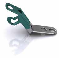
6 Lamina Elevator ( ) Expandable Laminoplasty Plate Technique Lifting the Lamina After the laminar trough and hinge have been prepared, the Lamina Elevator can be used to lift the fully-cut lamina. This instrument is designed such that the Expandable Laminoplasty Plate can fit between the prongs of the Lamina Elevator. The Lamina Elevator can remain attached to the lamina during plate placement. Note: Care should be taken not to use excessive force when lifting the lamina as this may result in hinge loosening. Lifting the Lamina 6
 To insert the plate, hold the Plate Holder / Expandable Laminoplasty Plate assembly with the green side facing up.")

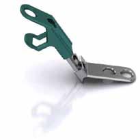
7 Placing the Plate Attach the Plate Holder to the plate by clamping the Plate Holder onto the top half of the plate (green side). Plate Holder ( ) To insert the plate, hold the Plate Holder / Expandable Laminoplasty Plate assembly with the green side facing up. Insert the mouth of the plate around the lifted lamina and place the foot of the plate (grey side) against the lateral mass of the open side. If necessary, lift the lamina using the plate, with a scooping action so that the foot can be placed. Tip: The Lamina Elevator can be left in place during this step, as the plate can fit between its prongs (see image to the left). Plate Placement through Lamina Elevator Once the mouth and the foot of the plate are positioned, the Lamina Elevator can be removed as the plate should hold the lamina open without assistance. Tip: The Plate Holder can be left in place for screw hole preparation. 7


 or to a power drill with an A/O connection.")
 Align the Drill Bit tip in the screw hole so that it is perpendicular to the plate. The Drill Bit features a stop which has been designed to prevent over-drilling.")
8 Screw Hole Preparation Note the recommended steps for screw hole preparation and screw insertion: a) Prepare / insert lateral mass side screws b) Expand plate c) Insert laminar screw This order is recommended to allow the plate to be positioned in the desired location before it is locked down. Keeping the Plate Holder attached, prepare the screw hole on the lateral mass side of the plate using either the Awl or a Drill Bit. Preparing / Inserting Lateral Mass Side Screw To use the Awl, align the pointed tip in the center of the plate screw hole such that it is perpendicular to the plate, then gently press and twist to penetrate the bone. The Awl point tip is 3mm in length and features a stop. When deployed through the plate, the Awl penetrates approximately 2.5mm of bone. Once the Awl has reached a 2.5mm depth the stop surface will contact the plate, preventing further penetration into bone. If drilling is preferred, attach the included Drill Bit to a Stryker Spine quick release handle (e.g. Aviator part # ) or to a power drill with an A/O connection. Drill Bits are available in 4, 6, and 8mm lengths and have a diameter of 1.2mm. The drill bits are designed to drill at the labeled depth when inserted through the plate. Awl ( ) Align the Drill Bit tip in the screw hole so that it is perpendicular to the plate. The Drill Bit features a stop which has been designed to prevent over-drilling. Carefully drill a pilot hole in the lateral mass until the shaft of the drill touches the plate. Drill Bit ( , , ) 8

 the screw pathway. Prior to insertion, confirm screw type by looking at the tip. The self-drilling screws have a sharper tip and cutting flute.")
9 Screwdriver ( ) Screwdriver Tip Screw Insertion The self-retaining Screwdriver features a square split tip to hold the screw head securely. To load bone screws, fully insert the tip of the Screwdriver into a screw head while the screw is in the screw caddy. Use the gauge in the screw caddy to confirm screw length. Note: Following either technique for screw preparation (Awl or Drill), use the 2.0mm self-drilling screws (magenta). The 2.4mm self-tapping screws should only be used as a rescue screw after a 2.0mm screw has been inserted into (and removed from) the screw pathway. Prior to insertion, confirm screw type by looking at the tip. The self-drilling screws have a sharper tip and cutting flute. With the Plate Holder still attached to the Expandable Laminoplasty Plate, insert bone screws one at a time through the Plate Holder and into the previously-prepared pilot holes. Turn the Screwdriver clockwise to advance the screw. Tighten the screw until it feels secure in bone and is flush with the plate. Do not continue to advance the screw beyond this point, as this may lead to stripping of the screw or screw hole. Gently rock the Screwdriver to disengage. Repeat this process to insert the second screw. Release the Plate Holder from the Expandable Laminoplasty Plate. The Expandable Laminoplasty Plate should now be properly fastened to the lateral mass of the chosen vertebral level and be holding the lamina in its mouth (as shown below). Insert Lateral Mass Screws through Plate Holder Plate in Position and Fastened to Lateral Mass 9
 pin engages the hole on the bottom (grey) half of the plate, then engage the top (angled side) pin in the hole at the top (green side) of the")

10 Expander Knob Plate Expansion If the Expandable Laminoplasty Plate is at a desired height, the laminar screw hole can be prepared. If more opening is required, use the Expander to expand the plate. Position the Expander so that the bottom (flat side) pin engages the hole on the bottom (grey) half of the plate, then engage the top (angled side) pin in the hole at the top (green side) of the plate. Expander ( ) Tip: To set the Expander in the Start position, rotate the handle counterclockwise until it stops. Then rotate clockwise for one full revolution. Tip: The grooves on the underside of the Expander are designed to fit over the screws on the lateral mass side of the plate. Use the grooves to help align the Expander to the plate. Tip: Keep Expander tilted forward to ensure engagement of its top pin with the Expandable Laminoplasty Plate. lubricate regularly To expand, be sure the Expander pins are fully seated in the plate, and gently turn the knob clockwise. The first click indicates that the Expandable Laminoplasty Plate has been adjusted to a height of 10mm; the second click indicates that the Expandable Laminoplasty Plate has been adjusted to a height of 12mm. Rotate the knob approximately complete turns for 1 click. The Expander and the plate both feature stops which are designed to prevent over-expansion or plate disassembly. After the desired height has been achieved, gently turn the Expander knob counterclockwise a half-turn and pull backwards on the instrument to disengage it from the plate. Note: Do not apply cantilever loads while the pins of the Expander are engaged with the plate as this may lead to pin breakage. Note: Lubricate the handle of the Expander regularly to ensure proper functioning of the instrument. Alternate Technique for Plate Expansion The Lamina Elevator can also be used to expand the plate. To follow this technique, apply counter force on the lateral mass side of the plate by placing the Screwdriver in the screw hole. Then place the Lamina Elevator under the lamina (around the plate). Lift up on the lamina while holding the Screwdriver in the lateral mass side screw hole. The plate will expand as needed. Note: Do not apply excessive force using this technique. 10 Note: The Alternate Technique for Plate Expansion requires insertion of the laminar screw prior to plate expansion.


11 Prepare Laminar Screw Pathway and Insert Screw With the plate in its expanded position, prepare the laminar screw pathway using either the Awl or Drill Bit (as described previously). Then insert the appropriate screw using the Screwdriver. Note: Care should be taken while inserting the laminar screw as the Plate Holder is no longer attached for use as a guide. Note: In cases where the hinge is loose or unstable, the Lamina Elevator may be used to lift the lamina to the top of the plate to facilitate drilling or screw insertion. Insert Laminar Screw Collapsing the Expandable Laminoplasty Plate The Expandable Laminoplasty Plate can be returned to its original height or collapsed ex situ using the Collapser Block. To collapse the plate, place the mouth of the plate (green side) under the positioning bar. Push on the top of the plate, while sliding the bottom half (grey side) closed. Note: The Expandable Laminoplasty Plate can be expanded and collapsed a maximum of 3 times. Place Mouth of Plate under Positioning Bar of the Collapser Block ( ) Note: When pressing down to collapse the Expandable Laminoplasty Plate try to keep pressure off the plate s expandable tab. Push Down on Green Side, while Sliding Grey Side Closed 11


12 Base Laminoplasty Plate Technique The Base Laminoplasty Plate can be used to provide additional support for a loose hinge. Use the Plate Holder to place the plate on the hinge so that the short side rests by the lateral mass and the longer side rests in-line with the lamina. Prepare screw holes and insert screws on the lateral mass side first, and then repeat for the lamina side. Repeat as needed for each desired level. Base Laminoplasty Plate attached to the Hinge Side Implant Removal Expandable Laminoplasty Plate To remove the Expandable Laminoplasty Plate, follow the implantation procedure in reverse. First, attach the Plate Holder to the Expandable Laminoplasty Plate making sure it grasps the plate securely. Next, seat the Screwdriver in the laminar screw and turn counterclockwise to back out the bone screw. Complete the same procedure for the lateral mass bone screws. Once all bone screws have been removed use the Lamina Elevator to pull back on the lamina, and remove the Expandable Laminoplasty Plate with the Plate Holder. Base Laminoplasty Plate To remove the Base Laminoplasty Plate, follow the implantation procedure in reverse. Seat the Screwdriver in the laminar screw and rotate counterclockwise to back out the bone screw. Complete the same procedure for the other laminar screw. Next, seat the screwdriver in one of the lateral mass screws and rotate counterclockwise to back out the screw. Complete the same procedure for the second lateral mass side screw. The Base Laminoplasty Plate is not compatible with the Plate Holder. 12
13 Implants Description Part # Expandable Laminoplasty Plate Base Laminoplasty Plate Ø2.0mm Self-Drilling Screw, 4mm Ø2.0mm Self-Drilling Screw, 6mm Ø2.0mm Self-Drilling Screw, 8mm Ø2.0mm Self-Drilling Screw, 10mm Ø2.4mm Self-Tapping Screw, 4mm Ø2.4mm Self-Tapping Screw, 6mm Ø2.4mm Self-Tapping Screw, 8mm Ø2.4mm Self-Tapping Screw, 10mm
14 Instruments Description Part # Laminoplasty Container Lamina Elevator Plate Holder Awl Expander Screwdriver Collapser Block Drill, 4mm Drill, 6mm Drill, 8mm Laminoplasty Screw Rack A Laminoplasty Plate Caddy B Laminoplasty Outer Case C Laminoplasty Inner Tray D 14
15 Product Information STRYKER SPINE Escalate NON STERILE PRODUCT DESCRIPTION The STRYKER Spine Escalate is a complete set of implants and instruments designed to allow for a systematic approach to laminoplasty procedures in the cervical spine. The system features an expandable plate, a hinge plate, bone screws, and a set of instruments to assist in implantation and removal of the devices. The screws to be used with the plates are available in various sizes and are designed to match the anatomical requirements. INDICATIONS The STRYKER Spine Escalate is intended for use in the lower cervical and upper thoracic spine (C3-T3) in laminoplasty procedures. The system is intended to hold the lamina open following a laminoplasty procedure. CONTRAINDICATIONS Contraindications may be relative or absolute. The choice of a particular device must be carefully weighed against the patient s overall evaluation. Circumstances listed below may reduce the chances of a successful outcome: Pathological bone conditions including, but not limited to, severe osteoporosis involving the spine, osteopenia, or certain metabolic disorders affecting osteogenesis. Active (fever, leukocytosis) or previous history of infection. Open wounds. Any neuromuscular deficit, which places an unusually heavy load on the device during the healing period. Any case not needing a laminoplasty procedure. Morbid Obesity that may result in inordinate loading of the device. Pregnancy A condition of senility, mental illness, or substance abuse potentially rendering the patient non-compliant with post-operative protocols. Foreign body sensitivity. Where material sensitivity is suspected, appropriate tests must be made prior to material selection or implantation. Other medical or surgical condition which would preclude the potential benefit of spinal implant surgery, such as the presence of, congenital abnormalities, elevation of sedimentation rate unexplained by other diseases, elevation of white blood cell count (WBC), or marked left shift in the WBC differential count. Any case not described in the Indications. As in any surgical condition, these contraindications can be relative or absolute and must be taken into account by the physician when making his decision. The above list is not exhaustive. PRE-OPERATIVE PRECAUTIONS brochures may be by requested from a distributor or from STRYKER Spine directly. Those using brochures published more than two years before the surgical intervention are advised to obtain an updated version. STRYKER Spine devices can only be used by doctors who are fully familiar with the surgical technique required and who have been trained to this end. The doctor operating must take care not to use the instruments to exert inappropriate stress on the spine or the implants and must scrupulously comply with any operating procedure described in the surgical technique provided by STRYKER Spine. For example, the forces exerted when repositioning an instrument in-situ must not be excessive as this is likely to causes injury to the patient. To reduce the risks of breakage, care must be taken not to distort the implants or nick, hit or score them with the instruments unless otherwise specified by the applicable STRYKER Spine Surgical technique. Extreme care must be taken when the instruments are used near vital organs, nerves or vessels. Unless otherwise specified on the label, the instruments may be reused after decontamination, cleaning and sterilization. REMOVAL OF IMPLANTS These implants are temporary internal fixation devices designed to stabilize the operative site during the normal healing process. After healing occurs, these devices serve no functional purpose and can be removed. Removal may also be recommended in other cases, such as: Corrosion with a painful reaction Migration of the implant, with subsequent pain and/or neurological, articular or soft tissue lesions Pain or abnormal sensations due to the presence of the implants Infection or inflammatory reactions Reduction in bone density due to the different distribution of mechanical and physiological stresses and strains Bone growth restraint due to the presence of the implants Failure or mobilization of the implant Instruments are provided by STRYKER Spine to be used to remove the implants. Any decision by a physician to remove the internal fixation device must take into consideration such factors as the risk to the patient of the additional surgical procedure as well as the difficulty of removal. Removal of an unloosened spinal screw may require the use of special instruments to disrupt the interface at the implant surface. This technique may require practice in the laboratory before being attempted clinically. Implant removal must be followed by adequate postoperative management to avoid fracture or re-fracture. Removal of the implant after fracture healing is recommended. Metallic implants can loosen, bend, fracture, corrode, migrate, cause pain or stress shield bone. WARNINGS & PRECAUTIONS The STRYKER Spine Escalate has not been evaluated for safety and compatibility in the MR environment. The STRYKER Spine Escalate has not been tested for heating or migration in the MR environment. CAUTION Federal law (USA) restricts these devices to sale by or on the order of a licensed physician. 15
16 US Operations 2 Pearl Court Allendale, New Jersey Phone: Fax: Web: EU Operations ZI Marticot Cestas France t: +33 (0) f: +33 (0) A surgeon must always rely on his or her own professional clinical judgment when deciding whether to use a particular product when treating a particular patient. Stryker does not dispense medical advice and recommends that surgeons be trained in the use of any particular product before using it in surgery. The information presented is intended to demonstrate the breadth of Stryker product offerings. A surgeon must always refer to the package insert, product label and/or instructions for use before using any Stryker product. Products may not be available in all markets because product availability is subject to the regulatory and/or medical practices in individual markets. Please contact your Stryker representative if you have questions about the availability of Stryker products in your area. Stryker Corporation or its divisions or other corporate affiliated entities own, use or have applied for the following trademarks or service marks: Aviator, Escalate, Stryker. All other trademarks are trademarks of their respective owners or holders. Literature Number: CVESCST11011 SC/GS 05/12 Copyright 2012 Stryker Printed in USA
Aviator Anterior Cervical Plating System System Overview. Visual and tactile confirmation Increased Angulation Simplified instrumentation
 Aviator Anterior Cervical Plating System System Overview Visual and tactile confirmation Increased Angulation Simplified instrumentation The Aviator anterior cervical plating system offers a unique double
Reflex Hybrid System Overview
 Spine Reflex Hybrid System Overview Anterior Cervical Plating System Introduction The Reflex Hybrid ACP System offers a low-profile anterior cervical plate along with a selection of bone screw types to
Aviator Anterior Cervical Plating System Surgical Technique
 Aviator Anterior Cervical Plating System Surgical Technique Table of Contents System Overview...3-4 Patient Positioning and Exposure...5 Implant Selection and Preparation.... 6-7 Screw Hole Preparation....
Reflex TM Surgical Technique. Anterior Cervical Plate
 Reflex TM Surgical Technique Anterior Cervical Plate Surgical Technique Acknowledgement: Stryker Spine extends their thanks to the following surgeons for their participation in the development of the Reflex
BLACKBIRD Spinal System
 BLACKBIRD Spinal System Cervical-Thoracic Spinal Fixation System The ChoiceSpine BLACKBIRD Cervical-Thoracic Spinal Fixation System is a comprehensive system for posterior fixation of the cervical and upper
OPERATIVE TECHNIQUE RIVAL REDUCE FRACTURE PLATING SYSTEM. foot & ankle trauma procedures
 OPERATIVE TECHNIQUE RIVAL REDUCE FRACTURE PLATING SYSTEM foot & ankle trauma procedures INTRODUCTION 3 SYSTEM DESCRIPTION 3 TECHNICAL DETAILS 4 SALES AND MARKETING CONFIGURATION 5 OPERATIVE TECHNIQUE 7
Gibralt. Occipito-Cervico Thoracc System. Operative Technique
 Gibralt Occipito-Cervico Thoracc System Operative Technique TABLE OF CONTENTS GIBRALT...1 OPERATIVE TECHNIQUE OVERVIEW...2 HOOK PLACEMENT...2 SCREW PLACEMENT...2 DETAILED OPERATIVE TECHNIQUE...4 PLACEMENT
VECTRA SURGICAL TECHNIQUE. Anterior cervical plate system. This publication is not intended for distribution in the USA.
 VECTRA Anterior cervical plate system This publication is not intended for distribution in the USA. SURGICAL TECHNIQUE Image intensifier control This description alone does not provide sufficient background
ACP 1. Anterior Cervical Plating System. Surgical Technique
 ACP 1 Anterior Cervical Plating System Surgical Technique Table of Contents System Overview.... 3 Patient Positioning and Exposure.... 5 Implant Selection and Preparation... 7 Screw Hole Preparation...
VBOSS. Surgical Technique. Vertebral Body Support System
 VBOSS Surgical Technique Vertebral Body Support System 1. System Description 1.1 Implants...3 1.2 Instruments...4 2. Indications...8 3. Patient Position...8 4. Surgical Approach 4.1 Choice of adequate
Technique Guide. Occipito-Cervical Fusion System. Implants and instruments designed to optimize fixation to the occiput.
 Technique Guide Occipito-Cervical Fusion System. Implants and instruments designed to optimize fixation to the occiput. Table of Contents Introduction Overview 2 AO ASIF Principles 4 Indications and Contraindications
VECTRA. SURGICAL TECHNIQUE. Anterior cervical plate system. This publication is not intended for distribution in the USA.
 VECTRA. Anterior cervical plate system. This publication is not intended for distribution in the USA. SURGICAL TECHNIQUE Contents Indications and contraindications Implants Vario Case Instruments Surgical
VariAx DistalFibula. Foot & Ankle. Locking Plate System. Operative Technique
 VariAx DistalFibula Locking Plate System Operative Technique Foot & Ankle Distal Fibula Fracture Repair Polyaxial Locking Technology Low Profile Design VariAx 2 Color Coded Screws and Instruments VariAx
Integra. Capture Screw System SURGICAL TECHNIQUE
 Integra Capture Screw System SURGICAL TECHNIQUE Table of Contents Indications... 2 Contraindications... 2 System Description... 2 System Features... 2 Cannulated Low-Profile Screws (AC-Series) Overview...
Integra. Stainless Headed Compression Screw System SURGICAL TECHNIQUE
 Integra Stainless Headed Compression Screw System SURGICAL TECHNIQUE Table of Contents Design Rationale...2 Indications...2 Contraindications...2 Surgical Technique Step 1: Inserting Guide Wire... 3 Step
Anterior Cervical Plate SURGICAL TECHNIQUE GUIDE. Surgeon Driven Innovation
 Anterior Cervical Plate SURGICAL TECHNIQUE GUIDE Surgeon Driven Innovation 1 The Snowmass Anterior Cervical Plate System is intended for the surgical treatment and correction of traumatic and pathologic
SURGICAL TECHNIQUE GUIDE
 SURGICAL TECHNIQUE GUIDE DANGER indicates an imminently hazardous situation which, if not avoided, will result in death or serious injury. WARNING indicates a potentially hazardous situation which, if
Xia 3 Reference Guide. Version 3-August 2015
 Xia 3 Reference Guide Xia 3 Reference Guide Version 3-August 2015 Table of Contents Implants 03 Blocker 03 Monoaxial Screws 04 Polyaxial Screws 05 Uniplanar Screws 06 Iliac Bolts 07 Rod-to-Rod Connectors
Technique Guide. 7.0 mm Cannulated Screws. Part of the Synthes Cannulated Screw System.
 Technique Guide 7.0 mm Cannulated Screws. Part of the Synthes Cannulated Screw System. Table of Contents Introduction 7.0 mm Cannulated Screws 2 AO Principles 3 Indications 4 Surgical Technique Surgical
Nakoma-SL Anterior Cervical Plating System Surgical Technique
 Anterior Cervical Plating System Surgical Technique Table of Contents Indications for Use................................1 Device Description............................... 1 Nakoma-SL Implant Key Features.........................2
Occipito-Cervical Fusion System. Implants and instruments designed to optimize fixation to the occiput.
 Occipito-Cervical Fusion System. Implants and instruments designed to optimize fixation to the occiput. Technique Guide This publication is not intended for distribution in the USA. Instruments and implants
UNIQUE PATIENTS SPECIFIC INDICATIONS IN ONE SYSTEM. Surgical Technique
 UNIQUE PATIENTS SPECIFIC INDICATIONS IN ONE SYSTEM Surgical Technique Joint Spine Sports Med Mecta-C Plate Surgical Technique 2 INDEX 1. INTRODUCTION 4 1.1 Mecta-C Cervical Plates 4 1.2 Bone Screws 4 1.3
7.0 mm Cannulated Screws
 Part of the DePuy Synthes Cannulated Screw System 7.0 mm Cannulated Screws Surgical Technique Table of Contents Introduction 7.0 mm Cannulated Screws 2 AO Principles 3 Indications 4 Surgical Technique
UNIQUE PATIENTS SPECIFIC INDICATIONS IN ONE SYSTEM. Surgical Technique
 UNIQUE PATIENTS SPECIFIC INDICATIONS IN ONE SYSTEM Surgical Technique Joint Spine Sports Med Mecta-C Plate Surgical Technique 2 INDEX 1. INTRODUCTION 4 1.1 Mecta-C Cervical Plates 4 1.2 Bone Screws 4 1.3
ThinLine Anterior Cervical Plate
 ThinLine Anterior Cervical Plate Surgical Technique Solutions by the people of Zimmer Spine. zimmerspine.com Designed for those times when less means more. From the people of Zimmer Spine. ThinLine is
Technique Guide. 4.5 mm Cannulated Screws. Part of the Synthes Cannulated Screw System.
 Technique Guide 4.5 mm Cannulated Screws. Part of the Synthes Cannulated Screw System. TableofContents Introduction 4.5 mm Cannulated Screws 2 AO Principles 3 Indications 4 Surgical Technique Surgical
ACLP Anterior Cervical Locking Plate System TECHNIQUE GUIDE
 ACLP Anterior Cervical Locking Plate System TECHNIQUE GUIDE Instruments and implants approved by the AO Foundation ACLP Anterior Cervical Locking Plate System The ACLP System is designed to reduce the
ACCS Anterior Cervical Compression System TECHNIQUE GUIDE
 ACCS Anterior Cervical Compression System TECHNIQUE GUIDE Original Instruments and Implants of the Association for the Study of Internal Fixation AO ASIF ACCS Anterior Cervical Compression System The Anterior
VariAx Fibula Locking Plate System
 VariAx Fibula Locking Plate System Operative Technique Distal Fibula Fracture Repair Polyaxial Locking Technology Low Profile Design 1 Contributing Surgeon: Bradley R. Merk, MD Associate Professor of Orthopaedic
3.5 mm Cannulated Screw Technique Guide
 3.5 mm Cannulated Screw Technique Guide An Integral Part of the SYNTHES Cannulated Screw System Original Instruments and Implants of the Association for the Study of Internal Fixation AO ASIF The 3.5 mm
Cervical Solutions. Lineum OCT. Spine System. Surgical Technique Guide
 Cervical Solutions Lineum OCT Spine System Surgical Technique Guide 2 Lineum OCT Spine System Surgical Technique Guide Designed to encourage optimal screw placement and procedural efficiency Lineum OCT
Vectra, Vectra-T and Vectra-One. Anterior cervical plating for spinal fusion.
 Vectra, Vectra-T and Vectra-One. Anterior cervical plating for spinal fusion. Technique Guide Instruments and implants approved by the AO Foundation Table of Contents Introduction Vectra, Vectra-T and
Table of Contents 2-6. Introduction. Indications Surgical Technique. Ordering Information 15-24
 Table of Contents Introduction Product information ExtremiFix Midsize Large Screw Offering Headless Screw Characteristics Design Features & Benefits Instrumentation Technical Details Calibrated Drill Bits
OPERATIVE TECHNIQUE RIVAL VIEW PLATING SYSTEM. foot & ankle reconstruction procedures
 OPERATIVE TECHNIQUE RIVAL VIEW PLATING SYSTEM foot & ankle reconstruction procedures INTRODUCTION 3 SYSTEM DESCRIPTION 3 TECHNICAL DETAILS 4 SALES AND MARKETING CONFIGURATION 5 OPERATIVE TECHNIQUE 7 OPERATIVE
Part of the DePuy Synthes Cannulated Screw System. 3.5 mm Cannulated Screws
 Part of the DePuy Synthes Cannulated Screw System 3.5 mm Cannulated Screws Surgical Technique Table of Contents Introduction 3.5 mm Cannulated Screws 2 AO Principles 3 Indications 4 Surgical Technique
OCCIPITO-CERVICAL FUSION SYSTEM Implants and instruments designed to optimize fixation to the occiput
 OCCIPITO-CERVICAL FUSION SYSTEM Implants and instruments designed to optimize fixation to the occiput Instruments and implants approved by the AO Foundation. This publication is not intended for distribution
Surgical Technique. Anterior Cervical Plating System
 Reflex Hybrid Surgical Technique Anterior Cervical Plating System Table of Contents Introduction 2 System Overview 3 Patient Positioning and Exposure 6 Implant Selection and Preparation 6 Bone Screw Hole
Surgical Technique. Deformity - Degenerative. Interbody Fusion. Tumour - Trauma. Cervical. Emerging Technology
 Surgical Technique Deformity - Degenerative Interbody Fusion Tumour - Trauma Cervical Emerging Technology MONARCH SPINE SYSTEM Contents Introduction & Philosophy 2 Surgical Technique Monarch Bolts with
MaxTorque. surgical technique. Cannulated Screw System. Foot & Ankle. OrthoHelix Technology
 MaxTorque Cannulated Screw System OrthoHelix Technology surgical technique Foot & Ankle 2 M A X T O R Q U E C A N N U L A T E D S C R E W S Y S T E M Table of Contents Advantages 3 Indications 4 Contraindications
MaxAn Anterior Cervical Plate System
 Surgical Technique MaxAn Anterior Cervical Plate System Designed to Help Minimize the Potential for Adjacent Level Ossification Allows for screw placement up to 30 cephalad on the superior end of the plate
Technique Guide. Modular Sternal Cable System. Flexibility and strength in sternal closure and repair.
 Technique Guide Modular Sternal Cable System. Flexibility and strength in sternal closure and repair. Table of Contents Introduction Overview 2 Indications and Contraindications 3 Surgical Technique A.
OPERATIVE TECHNIQUE RIVAL BITE HEADED CANNULATED AND HEADLESS COMPRESSION SCREWS. foot & ankle applications
 OPERATIVE TECHNIQUE RIVAL BITE HEADED CANNULATED AND HEADLESS COMPRESSION SCREWS foot & ankle applications INTRODUCTION 3 SYSTEM DESCRIPTION 3 TECHNICAL DETAILS 4 SALES AND MARKETING CONFIGURATION 6 OPERATIVE
Surgical Technique 1
 Surgical Technique 1 D-RAD SMART PACK Single-Use Volar Distal Radius Plating System Surgical Technique Table of Contents Indications... 3 Contraindications... 3 D-RAD SMART PACK product overview... 4 Instrumentation...
SlimLine Anterior Cervical Plate
 SlimLine Anterior Cervical Plate Surgical Technique Solutions by the people of Zimmer Spine. zimmerspine.com Efficient Design. Proven Results. From the people of Zimmer Spine. SlimLine is backed by an
PAC PLATE A N T E R I O R C E RV I CA L P L AT E SYST E M S U R G I C A L T E C H N I Q U E
 PAC PLATE A N T E R I O R C E RV I CA L P L AT E SYST E M S U R G I C A L T E C H N I Q U E PAC PLATE ANTERIOR CERVICAL PLATE SYSTEM Table of Contents INTRODUCTION System Overview... 1 SURGICAL TECHNIQUE
Technique Guide. Synapse System. An enhanced set of instruments and implants for posterior stabilization of the cervical and upper thoracic spine.
 Technique Guide Synapse System. An enhanced set of instruments and implants for posterior stabilization of the cervical and upper thoracic spine. Table of Contents Introduction Synapse System 2 AO Principles
VariAxFibula. Fibula Fractures. Locking Plate System. Operative Technique
 Foot and Ankle VariAxFibula Locking Plate System Operative Technique Fibula Fractures Distal Fibula Fracture Repair Polyaxial Locking Technology Low Profile Design VariAx Fibula Locking Plate System Contributing
CSLP Variable Angle. For Use with the Cervical Spine Locking Plate System TECHNIQUE GUIDE. Self-drilling Screw. Variable Screw Angulation
 CSLP Variable Angle For Use with the Cervical Spine Locking Plate System TECHNIQUE GUIDE Self-drilling Screw Variable Screw Angulation Original Instruments and Implants of the Association for the Study
ThinLine. Surgical Technique. Anterior Cervical Plate. zimmerspine.com
 ThinLine Anterior Cervical Plate Surgical Technique zimmerspine.com Designed for those times when less means more. From the people of Zimmer Spine. The ThinLine System is the lowest profile plate in the
Operative Technique Distal Fibula Fracture Repair Polyaxial Locking Technology Low Profile Design
 VariAx Fibula Locking Plate System Operative Technique Distal Fibula Fracture Repair Polyaxial Locking Technology Low Profile Design Contributing Surgeon: Bradley R. Merk, MD Associate Professor of Orthopaedic
VBOSS Surgical Technique
 VBOSS Surgical Technique 1 2 CONTENT 1. System Description 4 1.1 Implants 4 1.2 Instruments 6 2. Indications 11 3. Patient Position 11 4. Surgical Approach 12 4.1 Choice of adequate Parallel Distractor
6.5 mm and 7.3 mm Cannulated Screws Technique Guide
 6.5 mm and 7.3 mm Cannulated Screws Technique Guide An Integral Part of the SYNTHES Cannulated Screw System Original Instruments and Implants of the Association for the Study of Internal Fixation AO ASIF
Instruments for Removing DePuy Synthes Screws. Screw Removal Set
 Instruments for Removing DePuy Synthes Screws Screw Removal Set Surgical Technique Table of Contents Introduction Screw Removal Set 2 Surgical Technique Preoperative Planning and Preparation 6 Removal
Instructions for Use. LCP Locking Compression Plate. Combine without Compromise.
 Instructions for Use LCP Locking Compression Plate. Combine without Compromise. Table of Contents LCP: Combine without Compromise 2 AO ASIF Principles of Osteosynthesis 4 Indications and Contraindications
Occipito-Cervical Fusion System
 Implants and Instruments designed to enhance Fixation to the Occiput Occipito-Cervical Fusion System Surgical Technique Image intensifier control This description alone does not provide sufficient background
90 SCREWDRIVER Minimally invasive drilling and screw insertion
 90 SCREWDRIVER Minimally invasive drilling and screw insertion This publication is not intended for distribution in the USA. SURGICAL TECHNIQUE This description alone does not provide sufficient background
URS Degen. Top loading pedicle screw system for posterior stabilization.
 URS Degen. Top loading pedicle screw system for posterior stabilization. Technique Guide This publication is not intended for distribution in the USA. Table of Contents Introduction URS Degen 2 AO Principles
SpeedTip CCS 5.0, 7.0
 SURGICAL TECHNIQUE STEP BY STEP SpeedTip CCS 5.0, 7.0 Cannulated Compression Screws APTUS 2 SpeedTip CCS 5.0, 7.0 Cannulated Compression Screws Contents 3 Introduction Product Materials Indications Contraindications
TwinFix Surgical Protocol. 3.2mm Cannulated Compression Screw System
 TwinFix Surgical Protocol Compression Screw System TwinFix Compression Screw System Indications for Use: The Stryker TwinFix Interfragmentary Compression Screw System is intended to be used for fractures
DISTAL RADIUS PLATES 3.5 mm / ANGULARLY STABLE. Distal radius plates 3,5 mm / angularly stable. Locking bone screws. Cortical bone screw
 SURGICAL NÁSTROJE TECHNIQUE PRO ARTROSKOPII DISTAL INSTRUMENTS RADIUS PLATES FOR ARTHROSCOPY 3.5 mm / ANGULARLY STABLE Distal radius plates 3.5 mm / angularly stable Indication The plates are used for
Distal Medial Tibia Plate Surgical Technique
 Locking Compression Technology by aap 1 Disclaimer This surgical technique is exclusively intended for medical professionals, especially physicians, and therefore may not be regarded as a source of information
DART-FIRE. Small Screw System SURGICAL TECHNIQUE
 DART-FIRE Small Screw System SURGICAL TECHNIQUE DART-FIRE Small Screw System SURGICAL TECHNIQUE Contents Chapter 1 4 Chapter 2 6 Appendix 1 9 Appendix 2 11 Introduction DART-FIRE Small Screw System Surgical
Technique Guide. 2.4/2.7 mm Locking Tarsal Plates. Talus Plate, Navicular Plate and Cuboid Plate.
 Technique Guide 2.4/2.7 mm Locking Tarsal Plates. Talus Plate, Navicular Plate and Cuboid Plate. Table of Contents Introduction 2.4/2.7 mm Locking Tarsal Plates 2 AO Principles 4 Indications 5 Clinical
DART-FIRE. Small Screw System SURGICAL TECHNIQUE
 DART-FIRE Small Screw System SURGICAL TECHNIQUE DART-FIRE Small Screw System Surgical Technique Contents Chapter 1 4 Chapter 2 6 Chapter 3 7 Appendix 1 10 Appendix 2 12 Introduction Intended Use DART-FIRE
Proximal Humerus Plate 3.5 Surgical Technique
 Locking Compression Technology by aap 1 Disclaimer This surgical technique is exclusively intended for medical professionals, especially physicians, and therefore may not be regarded as a source of information
BioDrive Micro Screw System
 At Biomet, engineering excellence is our heritage and our passion. For over 25 years, through various divisions worldwide, we have applied the most advanced engineering and manufacturing technology to
HCS 1.5. The countersinkable compression screw.
 HCS 1.5. The countersinkable compression screw. Surgical Technique This publication is not intended for distribution in the USA. Instruments and implants approved by the AO Foundation. Table of Contents
OPERATIVE TECHNIQUE CENTURION POSTERIOR OCCIPITAL CERVICO-THORACIC (POCT) SYSTEM
 SYSTEM") OPERATIVE TECHNIQUE CENTURION POSTERIOR OCCIPITAL CERVICO-THORACIC (POCT) SYSTEM TABLE OF CONTENTS Introduction 2 System Overview 3 Cervical Operative Technique 4 Thoracic Operative Technique 10 Thoracic
OPERATIVE TECHNIQUE CENTURION POSTERIOR OCCIPITAL CERVICO-THORACIC (POCT) SYSTEM TABLE OF CONTENTS Introduction 2 System Overview 3 Cervical Operative Technique 4 Thoracic Operative Technique 10 Thoracic
Small Plate and Screw System SURGICAL TECHNIQUE
 MINI MAXLOCK EXTREME Small Plate and Screw System SURGICAL TECHNIQUE Contents Key Design Features 2 Surgical Technique 3 Implants and Instruments 9 Proper surgical procedures and techniques are the responsibility
Surgical Technique ANAX TM OCT. Spinal System
 Surgical Technique ANAX TM OCT Spinal System Product Overview Occipital plate Medial occipital plate (Small, Medium, Large) Lateral occipital plate (Small, Medium, Large) Cortical screw (D4.5mm), Rescue
Humeral Nail System Procedural Steps.
 Humeral Nail System Procedural Steps www.carbo-fix.com Table of Contents Introduction..3 Instrumentation Set... 8 Procedural Steps: Humeral Nail.........10 Procedural Steps: Proximal Humeral Nail.....13
DLS Dynamic Locking Screw. Combined with LCP Locking Compression Plate.
 DLS Dynamic Locking Screw. Combined with LCP Locking Compression Plate. Instructions for Use Discontinued June 2016 DSEM/TRM/0517/0844(1) Table of Contents Introduction DLS Dynamic Locking Screw 2 Indications
Surgical Technique. Customer Service:
 Patent Pending CAUTION: Federal Law (USA) restricts this device to sale by or on the order of a physician. Notes This page is blank INDICATIONS FOR USE The Extremity Medical Hallu X Intramedullary Fusion
Technique Guide. Synapse System. An enhanced set of implants and instruments for posterior stabilization of the cervical and upper thoracic spine.
 Technique Guide Synapse System. An enhanced set of implants and instruments for posterior stabilization of the cervical and upper thoracic spine. Image intensifier control Warning This description alone
ISO Plate SURGICAL TECHNIQUE
 MINI MAXLOCK EXTREME ISO Plate SURGICAL TECHNIQUE Contents Table of Contents Key Design Features 2 Surgical Technique 3 Implants and Instruments 8 Key Design Features The MINI MAXLOCK EXTREME ISO (Intraosseous
Top Loading Pedicle Screw and Hook System for Posterior Stabilization. URS System. Surgical Technique
 Top Loading Pedicle Screw and Hook System for Posterior Stabilization URS System Surgical Technique Image intensifier control This description alone does not provide sufficient background for direct use
Interlagos Retractor System Surgical Technique
 Interlagos Retractor System Surgical Technique TABLE OF CONTENTS Instructions for Use Design Rationale Surgical Technique 1. Pre-Operative Preparation 2. Pedicle Preparation 3. Primary Retraction 4. Secondary
The Percutaneous Reduction Forceps Technique Guide
 The Percutaneous Reduction Forceps Technique Guide Indications + Product Overview Introduction The Percutaneous Reduction Forceps The Percutaneous Reduction Forceps facilitate standard technique for fixation
MEDIALMAX System SURGICAL TECHNIQUE
 MAXLOCK EXTREME MEDIALMAX System SURGICAL TECHNIQUE Contents The MEDIALMAX Advantage Design Feature Various flex options POCKETLOCK Technology Anatomic design Advantage Provides the surgeon with multiple
Technique Guide. Quadrilateral Surface Plates 3.5. Part of the Low Profile Pelvic System 3.5.
 Technique Guide Quadrilateral Surface Plates 3.5. Part of the Low Profile Pelvic System 3.5. Table of Contents Introduction Quadrilateral Surface Plates 3.5 2 AO Principles 4 Indications 5 Surgical Technique
Peanut Growth Control Plating System. Surgical Technique
 Peanut Growth Control Plating System Surgical Technique 1 Peanut Growth Control Plating System Table of Contents System Design Features... 2 Instrument Tray... 5 Implant Caddy... 6 Surgical Technique...
Universal Humeral Nail
 990210009 INDEX Indications Preoperative Planning Patient Position Surgical Technique - Step 1 Open Humerus - Step 2 Calibrate The Nail - Step 3 Insert Nail - Step 4 Proximal Locking - Step 5 Assemble
HCS 2.4/3.0. The countersinkable compression screw.
 Technique Guide HCS 2.4/3.0. The countersinkable compression screw. Table of Contents Introduction Features and Benefits 2 Functional Principle 3 Indications 4 Surgical Technique Hand Scaphoid 5 Foot
Apex & HA Apex Pins. Pin Fixation System. Half Pins, Transfixing Pins HA Coated Half Pins for long term fixation Instruments
 Apex & HA Apex Pins Pin Fixation System Half Pins, Transfixing Pins HA Coated Half Pins for long term fixation Instruments Apex Pins This publication sets forth detailed recommended procedures for using
DART-FIRE. Small Screw System SURGIC A L T ECHNIQUE
 DART-FIRE Small Screw System SURGIC A L T ECHNIQUE Contents Headline Headline PREFACE Chapter 1 4 Chapter 2 6 Chapter 3 7 Appendix A 10 Appendix B 12 Introduction Intended Use DART-FIRE Small Screw System
Thoracolumbar Solutions. Vitality Spinal Fixation System. Surgical Technique Guide
 Thoracolumbar Solutions Vitality Spinal Fixation System Surgical Technique Guide Vitality Spinal System Surgical Technique Vitality Spinal System Surgical Technique Description, Indications and Contraindications...
Mecron Cannulated Screws
 Surgical Technique and Ordering Information 2 Table of contents Description... 4 Indications for use... 4 Contraindications... 4 State-of-the-art design features... 5 Surgical Technique... 6 Surgery Steps
The information contained in this document is intended for healthcare professionals only.
 The information contained in this document is intended for healthcare professionals only. Apex Pin Fixation System Half Pins, Transfixing Pins & Instruments 1 Table of Contents Introduction.......................................................................01
Lag Screw Device TECHNIQUE GUIDE. Indicated for symphyseal fracture fixation of the mandible. Instruments and implants approved by the AO Foundation
 Lag Screw Device TECHNIQUE GUIDE Indicated for symphyseal fracture fixation of the mandible Instruments and implants approved by the AO Foundation Lag Screw Device Indicated for symphyseal fracture fixation
Surgical Technique. and Ordering Information
 Surgical Technique and Ordering Information INTRODUCTION CONTENTS The SKYLINE Anterior Cervical Plate provides a versatile system of implants and instruments to accommodate the needs and individual preferences
1.5 MM LCP SYSTEM. For treatment of fractures and arthrodeses of canines and felines SURGICAL TECHNIQUE
 1.5 MM LCP SYSTEM For treatment of fractures and arthrodeses of canines and felines SURGICAL TECHNIQUE TABLE OF CONTENTS INTRODUCTION 1.5 mm LCP System 2 AO Principles 4 SURGICAL TECHNIQUE Reduce Fracture
Technique Guide Supplement. Standard DHS Lag Screw with LCP DHHS Sideplate.
 Technique Guide Supplement Standard DHS Lag Screw with LCP DHHS Sideplate. Table of Contents Surgical Technique Standard DHS Lag Screw with LCP DHHS 2 Sideplate Technique DHS One-step Lag Screw with DHHS
Ascent. Posterior Occipital Cervico-Thoracic (POCT) System
 System") Ascent Posterior Occipital Cervico-Thoracic (POCT) System Ascent Posterior Occipital Cervico-Thoracic (POCT) System VERSATILITY, RELIABILITY AND SIMPLICITY FOR COMPLEX SPINAL PROCEDURES The Ascent POCT
Ascent Posterior Occipital Cervico-Thoracic (POCT) System Ascent Posterior Occipital Cervico-Thoracic (POCT) System VERSATILITY, RELIABILITY AND SIMPLICITY FOR COMPLEX SPINAL PROCEDURES The Ascent POCT
CETRA ANTERIOR CERVICAL PLATE
 CETRA TM ANTERIOR CERVICAL PLATE The CETRA Anterior Cervical Plate System offers a low profile titanium alloy plate with an intuitive locking mechanism, large graft windows, a high degree of screw angulation
VariAx Foot Locking Plate System
 VariAx Foot Locking Plate System Operative Technique Trauma and Deformity Correction Polyaxial Locking Technology Comprehensive Calcaneal Fracture Plates Table of Contents 1. Introduction 3 2. Overview
Back to health. Back to work. Back to life.
 TECHNIQUE Back to health. Back to work. Back to life. U PLUS 90 INSTRUMENTATION OVERVIEW W&H IMPLANTMED POWER UNIT OVERVIEW Low-profile Primary Guides Compresses the U-clip to match rib thickness Clamps
MatrixMANDIBLE Preformed Reconstruction Plates. Preshaped to the mandibular anatomy.
 MatrixMANDIBLE Preformed Reconstruction Plates. Preshaped to the mandibular anatomy. Technique Guide CMF Matrix Table of Contents Introduction MatrixMANDIBLE Preformed Reconstruction Plates 2 AO Principles
V2F Anterior Fixation System
 TM V2F Anterior Fixation System Surgical Technique Solutions by the people of Zimmer Spine. zimmerspine.com Traditional approach. New Technique. From the people of Zimmer Spine. The V2F Anterior Fixation
MTP Fusion Surgical Technique
 MTP Fusion Surgical Technique Patent and Patent Pending CAUTION: Federal Law (USA) restricts this device to sale by or on the order of a physician. INDICATIONS FOR USE The Omni Foot Plating System is intended
Lineum OCT Spine System
 Surgical Technique Lineum OCT Spine System Designed to Encourage Optimal Screw Placement and Procedural Efficiency Game Changing Translation Screw 3.0mm of medial/lateral translation encourages optimal