OCCIPITO-CERVICAL FUSION SYSTEM Implants and instruments designed to optimize fixation to the occiput
|
|
|
- Dina Ford
- 6 years ago
- Views:
Transcription


1 OCCIPITO-CERVICAL FUSION SYSTEM Implants and instruments designed to optimize fixation to the occiput Instruments and implants approved by the AO Foundation. This publication is not intended for distribution in the USA. SURGICAL TECHNIQUE
2 Image intensifier control Warning This description alone does not provide sufficient background for direct use of the instrument set. Instruction by a surgeon experienced in handling these instruments is highly recommended. Reprocessing, Care and Maintenance of Synthes Instruments For general guidelines, function control and dismantling of multi-part instruments, please contact your local sales representative or refer to:
3 TABLE OF CONTENTS INTRODUCTION Occipito-Cervical Fusion System 2 AO Principles 4 Indications and Contraindications 5 SURGICAL TECHNIQUE Preparation 6 Occipito-Cervical Fixation with Occipital Plate 8 Occipito-Cervical Fixation with Occipital Clamps 21 Occipito-Cervical Fixation with Occiput Rods 31 Optional Technique: Using OC-Connector Top Loading with Occipital Plate 41 Optional Technique: Using OC-Connector Top Loading with Occipital Clamps 49 PRODUCT INFORMATION Implants 57 Instruments 64 Occipito-Cervical Fusion System Compatibility 68 BIOMATERIAL IMPLANTS Biomaterial Implants 69 ASSEMBLY GUIDE Depth Gauge Disassembly 70 Drill and Tap Sleeve with Scale Disassembly 71 Tap for Cortex Screw Disassembly 72 Occipito-Cervical Fusion System Surgical Technique DePuy Synthes 1


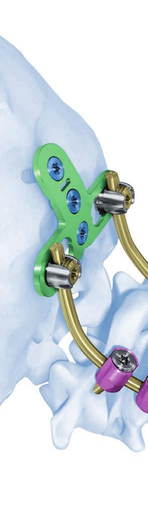
4 OCCIPITO-CERVICAL FUSION SYSTEM Implants and instruments designed to optimize fixation to the occiput. The Synthes Occipito-Cervical Fusion System is intended to provide stabilization and promote fusion of the occipito- cervical junction. The Occipito-Cervical Fusion System includes a complete set of implants and instruments designed to optimize fixation to the occiput and easily connect with all Synthes posterior cervical and thoracic rod-screw systems. Occipital Plate The Occipital Plate is available as a medial or lateral wedge, 50 mm or 60 mm wide. The plate attaches to the Occiput with screws. Bead-blasted lower surface to minimize intraoperative slippage Variable rod attachment body to allow for rotation and lateral / medial adjustment Low plate profile, 2 mm Allow 15 screw angulation Bend grooves for bending Available to support either B 3.5 mm or B 4.0 mm straight or pre-bent rods Versatile fixation possibilities to the Occiput The Occipito-Cervical Fusion System offers several implant options to maximize fixation to the occiput and minimize the implant footprint. Occipital plate, medial Occipital plate, lateral Occiput rods Occipital clamps, 1 hole Occipital clamps, 2 holes 1 DePuy Synthes Occipito-Cervical Fusion System Surgical Technique
 Occipital clamps Facilitates connection to rods Small footprint, low profile Available to support either B 3.5 mm or B 4.")
 TAN screws Blunt tip 4 mm 18 mm long in 2 mm increments Self-retaining Stardrive T15 interface Occipito-Cervical Fusion System Surgical Technique")
5 OC-Connector Features top-loading technology Facilitates connection from Occipital Plate/Clamp to Synapse screw Available straight or pre-bent 110 Available as B 3.5 mm and B 4.0 mm TAN (Ti-6Al-7Nb) Occipital clamps Facilitates connection to rods Small footprint, low profile Available to support either B 3.5 mm or B 4.0 mm straight or pre-bent rods Pure titanium (TICP) and TAN (Ti-6Al-7Nb) One and two screw hole configurations available Occipital screws B 4.5 mm TAN screws or B 5.0 mm (rescue) TAN screws Blunt tip 4 mm 18 mm long in 2 mm increments Self-retaining Stardrive T15 interface Occipito-Cervical Fusion System Surgical Technique DePuy Synthes 1
6 AO PRINCIPLES In 1958, the AO formulated four basic principles, which have become the guidelines for internal fixation. 1 These are: Anatomical alignment Stable internal fixation Preservation of blood supply Early, active mobilization The fundamental aims of fracture treatment in the limbs and fusion of the spine are the same. A specific goal in the spine is returning as much function as possible to the injured neural elements. 2 AO Principles as Applied to the Spine 3 Anatomical alignment In the spine, this means reestablishing and maintaining the natural curvature and the protective function of the spine. By regaining this natural anatomy, the biomechanics of the spine can be improved and a reduction of pain may be experienced. Preservation of blood supply The proper atraumatic technique enables minimal retraction or disturbance of the nerve roots and dura, and maintains the stability of the facet joints. The ideal surgical technique and implant design minimize damage to anatomical structures, i.e. facet capsules and soft tissue attachments remain intact, and create a physiological environment that facilitates healing. Early, active mobilization The ability to restore normal spinal anatomy may permit the immediate reduction of pain, resulting in a more active, functional patient. The reduction in pain and improved function can result when a stable spine is achieved. Stable internal fixation In the spine, the goal of internal fixation is to maintain not only the integrity of a mobile segment, but also to maintain the balance and the physiologic three-dimensional form of the spine. 3 A stable spinal segment allows bony fusion at the junction of the lamina and pedicle. 1 Müller ME, Allgöwer M, Schneider R, Willenegger H (1995) Manual of Internal Fixation. 3 rd, exp. a. completely rev. ed Corr. 3 rd printing. Berlin, Heidelberg, New York: Springer 2 Ibid. 3 Aebi M, Arlet V, Webb JK (2007) AOSPINE Manual (2 vols), Stuttgart, New York: Thieme 4 DePuy Synthes Occipito-Cervical Fusion System Surgical Technique
7 INDICATIONS AND CONTRAINDICATIONS The Synthes Occipito-Cervical Fusion System in combination with a Synthes posterior screw-rod system (e.g. Synapse and Axon) is intended to provide stabilization to promote fusion of the cervical spine and occipito-cervical junction (Occiput-Th3) for the following indications: Indications Occipito-cervical and upper cervical spine instabilities: Rheumatoid arthritis Congenital anomalies Posttraumatic conditions Tumors Infections Instabilities in the lower cervical and upper thoracic spine: Posttraumatic conditions Tumors Iatrogenic instabilities following laminectomy etc. Degenerative and painful posttraumatic conditions in the lower cervical and upper thoracic spine. Anterior cervical fusions requiring additional posterior stabilization. Contraindications Spinal destruction accompanied by a loss of ventral support (caused by tumors, fractures and infections) results in major instability of the cervical spine and upper thoracic spine. In this situation, stabilization with this system alone is not sufficient. Additional anterior stabilization is crucial. Severe osteoporosis Occipito-Cervical Fusion System Surgical Technique DePuy Synthes 5
8 PREPARATION 1 Preparation Recommended sets Occipital-Cervical Fusion System 3.5 in Vario Case (All implants are non-sterile and for B 3.5 mm rods only) Synapse System 3.5 in Vario Case (All implants are non-sterile and for B 3.5 mm rods only) Implants are also available sterile. Optional sets Occipital-Cervical 4.0 Fusion System in Vario Case (All implants are sterile and for B 4.0 mm rods only) Synapse System 4.0 in Vario Case (All implants are sterile and for B 4.0 mm rods only) Axon in Vario Case Note: Rods for the Synapse System are available in B 3.5 mm and B 4.0 mm. Where B 4.0 mm rods are used, these must be combined with Synapse 4.0 screws/oc-fusion 4.0 plates/ clamps and the Synapse/Occipito-Cervical Fusion 4.0 Instrument set listed above. 6 DePuy Synthes Occipito-Cervical Fusion System Surgical Technique
9 2 Preoperative planning All necessary imaging studies should be available to plan implant placement and visualize patient anatomy. 3 Position the patient Patient positioning is critical for occipito-cervical fusion procedures. The patient should be placed on the operating table in the prone position with the patient s head securely immobilized. Proper patient position should be confirmed via direct visualization and by radiograph prior to draping. Warning: Always use caution when positioning the patient, as physiological alignment may not be attainable. 4 Approach Use the standard surgical approach to expose the spinous processes and laminae of the vertebrae to be fused, and the external occipital protuberance. 5 Assemble instruments The following instruments have to be assembled prior to use: Depth Gauge Tap for cortex screw Drill and tap sleeve with scale Assemble instruments according to the assembling instructions found from page 70 onwards, or refer to: for detailed information. Occipito-Cervical Fusion System Surgical Technique DePuy Synthes 7
10 OCCIPITO-CERVICAL FIXATION WITH OCCIPITAL PLATE Shown in combination with Synapse; can also be used with Axon 1 Fixation to the cervical and upper thoracic spine Recommended set Synapse System 3.5 in Vario Case Optional sets Synapse System 4.0 in Vario Case Axon in Vario Case Insert bone screws and/or hooks into the cervical and upper thoracic spine as required by the patient s pathology. The technique is described in the Synapse Technique Guide ( ) or Axon Technique Guide ( ). 8 DePuy Synthes Occipito-Cervical Fusion System Surgical Technique
11 2 Determine shape and size of occipital plate Instruments / Bending Template for Occipital Plate, medial, small/large / Bending Template for Occipital Plate, lateral, small/large Plate Holder Select a bending template of the plate style estimated to best fit the occiput. Estimate the medial/lateral distance of the rods to determine the appropriate plate size. Contour the plate template to fit the anatomy. Occipito-Cervical Fusion System Surgical Technique DePuy Synthes 9


12 Occipito-Cervical Fixation with Occipital Plate 3 Contour occipital plate Instrument Bending Pliers for Occipital Plate Use the bending pliers for contouring the plate to fit the anatomy. They can be used across any section of the plate including the area lateral of the rod attachment bodies. Optional instrument Vice Grip, length 180 mm To create more acute bends vice grips can be used. Notes: Extreme bending over the rod attachment body travel slot will limit the amount of medial/lateral adjustment in the rod attachment body. Extreme bending over the screw holes will limit the ability to insert the screw properly. Warning: Reverse bending of the plates should not be attempted. This side must point upwards in relation to the plate. Rod Attachment Body Rod Attachment Body Travel Slot 11 DePuy Synthes Occipito-Cervical Fusion System Surgical Technique

13 4 Drill pilot hole Instruments Drill and Tap Sleeve with Scale for Nos and Drill Bit B 3.2 mm with Stop, length 245/69 mm, 2-flute, for Quick Coupling Handle with Quick Coupling Plate Holder Optional Instrument B 3.2 mm Drill Bit with flexible shaft, for Quick Coupling Set the drill and tap sleeve to the desired depth. Slide back the latch of the drill and tap sleeve to release its inner tube. Adjust position of inner tube in window so that the mark on the inner tube indicates the required depth. Release the latch to lock the drill and tap sleeve at the desired depth. Ensure that the plate is correctly positioned according to the patients anatomy before drilling. Drill to desired trajectory and depth using the drill bit and the drill and tap sleeve. Drilling must occur through the occipital plate to ensure proper drilling depth. Occipito-Cervical Fusion System Surgical Technique DePuy Synthes 11
14 Occipito-Cervical Fixation with Occipital Plate 5 Measure hole depth Instrument Depth Gauge for Screws B 3.5 to 5.0 mm, measuring range up to 50 mm Use the depth gauge to confirm hole depth and select the corresponding screw length. The depth gauge must sit directly on the bone. Note: The depth gauge measures the working length. If reading e.g. 10 mm on the depth gauge, select a 10 mm screw. Warning: Do not insert depth gauge too deep in order to confirm correct hole depth and to avoid damage to soft tissue. 11 DePuy Synthes Occipito-Cervical Fusion System Surgical Technique

 to the desired depth. Lock the tap sleeve by turning down the locking nut (2) until it contacts the tap sleeve.")
15 6 Tap Instruments Drill and Tap Sleeve with Scale, for Nos and Tap for Cortex Screw B 4.5 mm, length 245 mm, for Quick Coupling Handle with Quick Coupling Tap to desired depth using the tap and the drill and tap sleeve. Tapping must occur through the occipital plate to ensure proper tapping depth. Note: Tapping is recommended for all screws. Optional instruments Tap for Cortex Screw B 4.5 mm, with Cardan Joint, length 245 mm, for Quick Coupling Holding Forceps for Rods B 3.5 mm, length 181 mm Set the tap depth by turning the tap sleeve (1) to the desired depth. Lock the tap sleeve by turning down the locking nut (2) until it contacts the tap sleeve. Finger tighten the locking nut. Use the holding forceps to provide axial force and stability. Tapping must occur through the occipital plate to ensure proper tapping depth. 1 2 Occipito-Cervical Fusion System Surgical Technique DePuy Synthes 11
16 Occipito-Cervical Fixation with Occipital Plate 7 Insert screw Instruments Screwdriver Shaft Stardrive 3.5, T15, self-holding, length 245 mm, for Quick Coupling Handle with Quick Coupling Load the selected B 4.5 mm occipital screw from the screw rack. Insert screw and tighten it provisionally. Note: A B 5.0 mm occipital screw may be used if the primary screw has less than optimal fixation. Optional instruments Screwdriver Shaft Stardrive T15, self-holding, with Cardan Joint, for Quick Coupling Holding Forceps for Rods B 3.5 mm, length 181 mm Alternatively the screwdriver shaft with cardan joint may be used to insert the selected screw. Use the holding forceps to provide axial force and stability. 11 DePuy Synthes Occipito-Cervical Fusion System Surgical Technique
17 8 Insert remaining screws Repeat steps 4 7 to insert the remaining screws. Note: A minimum of three screws is recommended. Occipito-Cervical Fusion System Surgical Technique DePuy Synthes 11

18 Occipito-Cervical Fixation with Occipital Plate 9 Contour trial rod Instrument Trial Rod B 3.5 mm Optional Instrument Template for Occipital Angles Contour the trial rod to fit the anatomy and to seat fully in the bone screws. Create the occipito-cervical bend and ensure sufficient rod length to connect with the occipital plate. When using the template for occipital angles, place the template into the saddle of the occipital plate and pivot the opposite arm until it matches the anatomy as required. Remove the template to read the required angle indicated. 11 DePuy Synthes Occipito-Cervical Fusion System Surgical Technique
19 10 Bend and cut rod Instruments Bending Pliers for Rods B 3.5 mm Cutting Pliers for Plates and Rods Optional Instrument Rod Shearer for Rods B 4 mm Contour the rod using the bending pliers to match the curve of the trial rod. The bending pliers can be used for both rods B 3.5 mm and B 4.0 mm. Cut the rod with the cutting pliers to the appropriate length. Warning: Repeated or reverse bending may weaken the rod. Occipito-Cervical Fusion System Surgical Technique DePuy Synthes 11
20 Occipito-Cervical Fixation with Occipital Plate 11 Rod attachment Instruments Holding Forceps for Rods B 3.5 mm, length 181 mm Screwdriver Shaft Stardrive 3.5, T15, self-holding, length 245 mm, for Quick Coupling Handle with Quick Coupling Positioning Instrument for Occipital Plate Optional Instrument Positioning Instrument for Occipital Plate, for Rods B 4.0 mm Use the positioning instrument to facilitate rod placement and locking screw insertion. Insert rod into the rod attachment body. Ensure that the rod extends slightly past the end of the plate. Provisionally tighten the locking screw using the screwdriver shaft stardrive. The holding forceps can be used for both rods B 3.5 mm and B 4.0 mm. 11 DePuy Synthes Occipito-Cervical Fusion System Surgical Technique

21 Optional instruments Screwdriver Shaft Stardrive T15, self-holding, with Cardan Joint, for Quick Coupling Holding Forceps for Rods B 3.5 mm, length 181 mm Alternatively the screwdriver shaft with cardan joint may be used for provisional tightening of the locking screw. Use the holding forceps to provide axial force and stability. 12 Insert rod in contralateral side Repeat steps 9 11 to insert rod on the contralateral side. Occipito-Cervical Fusion System Surgical Technique DePuy Synthes 11
22 Occipito-Cervical Fixation with Occipital Plate 13 Final tightening Instruments Screwdriver Shaft Stardrive 3.5, T15, self-holding, length 245 mm, for Quick Coupling Handle with Quick Coupling Positioning Instrument for Occipital Plate Optional Instrument Positioning Instrument for Occipital Plate, for Rods B 4.0 mm Firmly tighten all occipital and locking screws using the screwdriver shaft Stardrive with the handle with quick coupling. To provide counter-torque for tightening the locking screws, the positioning instrument may be used. Optional instruments Screwdriver Shaft Stardrive T15, self-holding, with Cardan Joint, for Quick Coupling Holding Forceps for Rods B 3.5 mm, length 181 mm Alternatively the screwdriver shaft with cardan joint may be used for final tightening of the occipital and locking screws. Use the holding forceps to provide axial force and stability. To provide counter-torque for tightening the locking screws, the positioning instrument may be used. 22 DePuy Synthes Occipito-Cervical Fusion System Surgical Technique
23 OCCIPITO-CERVICAL FIXATION WITH OCCIPITAL CLAMPS Shown in combination with Synapse; can also be used with Axon 1 Fixation to the cervical and upper thoracic spine Recommended set Synapse System 3.5 in Vario Case Optional sets Synapse System 4.0 in Vario Case Axon in Vario Case Insert bone screws and/or hooks into the cervical and upper thoracic spine as required by the patient s pathology. The technique is described in the Synapse Technique Guide ( ) or Axon Technique Guide ( ). Occipito-Cervical Fusion System Surgical Technique DePuy Synthes 22
24 Occipito-Cervical Fixation with Occipital Clamps 2 Contour trial rod Instrument Trial Rod B 3.5 mm Contour the trial rod to fit the anatomy and to seat fully in the bone screws. Create the occipito-cervical bend and ensure sufficient rod length to connect with the occipital clamp. 22 DePuy Synthes Occipito-Cervical Fusion System Surgical Technique
25 3 Bend and cut rod Instruments Bending Pliers for Rods B 3.5 mm Cutting Pliers for Plates and Rods Optional Instrument Rod Shearer for Rods B 4 mm Contour the rod using the bending pliers to match the curve of the trial rod. The bending pliers can be used for both rods B 3.5 mm and B 4.0 mm. Cut the rod with the cutting pliers to the appropriate length. Warning: Repeated or reverse bending may weaken the rod. Occipito-Cervical Fusion System Surgical Technique DePuy Synthes 22
26 Occipito-Cervical Fixation with Occipital Clamps 4 Attach occipital clamp to rod Instruments Handle with Quick Coupling Screwdriver Shaft Stardrive 3.5, T15, self-holding, length 245 mm, for Quick Coupling Holding Forceps for Rods B 3.5 mm, length 181 mm Provisionally attach the occipital clamp to the rod by tightening the set screw in the clamp. Note: The holding forceps can be used for both rods B 3.5 mm and B 4.0 mm. 22 DePuy Synthes Occipito-Cervical Fusion System Surgical Technique
27 5 Drill pilot hole Instruments Drill and Tap Sleeve with Scale for Nos and Drill Bit B 3.2 mm with Stop, length 245/69 mm, 2-flute, for Quick Coupling Handle with Quick Coupling Holding Forceps for Rods B 3.5 mm, length 181 mm Optional Instrument Drill Bit B 3.2 mm with flexible shaft, for Quick Coupling Set the drill and tap sleeve to the desired depth. Slide back the latch of the drill and tap sleeve to release its inner tube. Adjust position of inner tube in window so that the mark on the inner tube indicates the required depth. Release the latch to lock the drill and tap sleeve at the desired depth. Drill to desired trajectory and depth using the drill bit and drill and tap sleeve. Drilling must occur through the occipital clamp to ensure proper drilling depth. Occipito-Cervical Fusion System Surgical Technique DePuy Synthes 22

28 Occipito-Cervical Fixation with Occipital Clamps 6 Measure hole depth Instrument Depth Gauge for Screws B 3.5 to 5.0 mm, measuring range up to 50 mm Use the depth gauge to confirm hole depth and select the corresponding screw length. The depth gauge must sit directly on the bone. Note: The depth gauge measures the working length. If reading e.g. 10 mm on the depth gauge, select a 10 mm screw. Warning: Do not insert depth gauge too deep in order to confirm correct hole depth and to avoid damage to soft tissue. 7 Tap Instruments Drill and Tap Sleeve with Scale for Nos and Tap for Cortex Screw B 4.5 mm, length 245 mm, for Quick Coupling Handle with Quick Coupling Tap to desired depth using the tap and the drill and tap sleeve. Tapping must occur through the occipital clamp to ensure proper tapping depth. Note: Tapping is recommended for all screws. 22 DePuy Synthes Occipito-Cervical Fusion System Surgical Technique
 to the desired depth. Lock tap sleeve by turning down the locking nut (2) until it contacts the tap sleeve.")
29 Optional instruments Tap for Cortex Screw B 4.5 mm, with Cardan Joint, length 245 mm, for Quick Coupling Holding Forceps for Rods B 3.5 mm, length 181 mm Set the tap depth by turning the tap sleeve (1) to the desired depth. Lock tap sleeve by turning down the locking nut (2) until it contacts the tap sleeve. Finger tighten the locking nut. Use the holding forceps to provide axial force and sta bility. Tapping must occur through the occipital clamp to ensure proper tapping depth. 1 2 Occipito-Cervical Fusion System Surgical Technique DePuy Synthes 22

30 Occipito-Cervical Fixation with Occipital Clamps 8 Insert screw Instruments Screwdriver Shaft Stardrive 3.5, T15, self-holding, length 245 mm, for Quick Coupling Handle with Quick Coupling Load the selected B 4.5 mm occipital screw from the screw rack. Insert screw and tighten it provisionally. Note: A B 5.0 mm occipital screw may be used if the primary screw has less than optimal fixation. Optional instruments Screwdriver Shaft Stardrive T15, self-holding, with Cardan Joint, for Quick Coupling Holding Forceps for Rods B 3.5 mm, length 181 mm Alternatively the screwdriver shaft with cardan joint may be used to insert the selected screw. Use the holding forceps to provide axial force and stability. 22 DePuy Synthes Occipito-Cervical Fusion System Surgical Technique
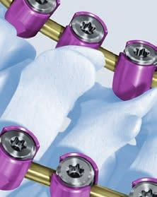
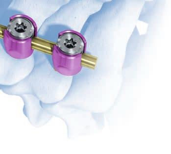
31 9 Insert remaining screws and clamps Repeat steps 4 8 to insert the remaining screws and clamps. Note: A minimum of two clamps per rod is recommended. 10 Insert second rod and remaining clamps and screws Repeat steps 2 9 to insert implants on the contralateral side. Occipito-Cervical Fusion System Surgical Technique DePuy Synthes 22
32 Occipito-Cervical Fixation with Occipital Clamps 11 Final tightening Instruments Screwdriver Shaft Stardrive 3.5, T15, self-holding, length 245 mm, for Quick Coupling Handle with Quick Coupling Firmly tighten all occipital screws and occipital clamp set screws using the screwdriver shaft with the handle with quick coupling. Optional instruments Screwdriver Shaft Stardrive T15, self-holding, with Cardan Joint, for Quick Coupling Holding Forceps for Rods B 3.5 mm, length 181 mm Alternatively the screwdriver shaft with cardan joint may be used for final tightening all occipital screws and occipital clamp set screws. Use the holding forceps to provide axial force and stability. 33 DePuy Synthes Occipito-Cervical Fusion System Surgical Technique
33 OCCIPITO-CERVICAL FIXATION WITH OCCIPUT RODS Shown in combination with Synapse; can also be used with Axon 1 Fixation to the cervical and upper thoracic spine Recommended set Synapse System 3.5 in Vario Case Optional sets Synapse System 4.0 in Vario Case Axon in Vario Case Insert bone screws and/or hooks into the cervical and upper thoracic spine as required by the patient s pathology. The technique is described in the Synapse Technique Guide ( ) or Axon Technique Guide ( ). Occipito-Cervical Fusion System Surgical Technique DePuy Synthes 33
34 Occipito-Cervical Fixation with Occiput Rods 2 Contour trial rod Instrument Occiput Trial Rod B 3.5 mm Contour the occiput trial rod to fit the anatomy and to seat fully in the bone screws. 33 DePuy Synthes Occipito-Cervical Fusion System Surgical Technique

35 3 Bend and cut occiput rod Instruments Bending Pliers for Rods B 3.5 mm Cutting Pliers for Plates and Rods Optional Instrument Rod Shearer for Rods B 4 mm Contour the occiput rod using the bending pliers to match the curve of the occiput trial rod. The bending pliers can be used for both B 3.5 and B 4.0 rods. Cut the rod with the cutting pliers to the appropriate length. Warning: Repeated or reverse bending may weaken the rod. Occipito-Cervical Fusion System Surgical Technique DePuy Synthes 33
36 Occipito-Cervical Fixation with Occiput Rods 4 Drill pilot hole Instruments Drill and Tap Sleeve with Scale for Nos and Drill Bit B 3.2 mm with Stop, length 245/69 mm, 2-flute, for Quick Coupling Handle with Quick Coupling Holding Forceps for Rods B 3.5 mm, length 181 mm Optional Instrument Drill Bit B 3.2 mm with flexible shaft, for Quick Coupling Set the drill and tap sleeve to the desired depth. Slide back the latch of the drill and tap sleeve to release its inner tube. Adjust position of inner tube in window so that the mark on the inner tube indicates the required depth. Release the latch to lock the drill and tap sleeve at the desired depth. Drill to desired trajectory and depth using the drill bit and the drill and tap sleeve. Drilling must occur through the occiput rod to ensure proper drilling depth. Note: The holding forceps can be used for both rods B 3.5 mm and B 4.0 mm. 33 DePuy Synthes Occipito-Cervical Fusion System Surgical Technique
37 5 Measure hole depth Instrument Depth Gauge for Screws B 3.5 to 5.0 mm, measuring range up to 50 mm Use the depth gauge to confirm hole depth and select the corresponding screw length. The depth gauge must sit directly on the bone. Note: The depth gauge measures the working length. If reading e.g. 10 mm on the depth gauge, select a 10 mm screw. Warning: Do not insert depth gauge too deep in order to confirm correct hole depth and to avoid damage to soft tissue. Occipito-Cervical Fusion System Surgical Technique DePuy Synthes 33

38 Occipito-Cervical Fixation with Occiput Rods 6 Tap Instruments Drill and Tap Sleeve with Scale for Nos and Tap for Cortex Screw B 4.5 mm, length 245 mm, for Quick Coupling Handle with Quick Coupling Tap to desired depth using the tap and the drill and tap sleeve. Tapping must occur through the occiput rod to ensure proper tapping depth. Note: Tapping is recommended for all screws. 33 DePuy Synthes Occipito-Cervical Fusion System Surgical Technique
 to the desired depth. Lock the tap sleeve by turning down the locking nut (2) until it contacts the tap sleeve.")
39 Optional instruments Tap for Cortex Screw B 4.5 mm, with Cardan Joint, length 245 mm, for Quick Coupling Holding Forceps for Rods B 3.5 mm, length 181 mm Set the tap depth by turning the tap sleeve (1) to the desired depth. Lock the tap sleeve by turning down the locking nut (2) until it contacts the tap sleeve. Finger tighten the locking nut. Use the holding forceps to provide axial force and stability. Tapping must occur through the occiput rod to ensure proper tapping depth. 1 2 Occipito-Cervical Fusion System Surgical Technique DePuy Synthes 33
40 Occipito-Cervical Fixation with Occiput Rods 7 Insert screw Instruments Screwdriver Shaft Stardrive 3.5, T15, self-holding, length 245 mm, for Quick Coupling Handle with Quick Coupling Load the selected B 4.5 mm occipital screw from the screw rack. Insert screw and tighten it provisionally. Note: An B 5.0 mm occipital screw may be used if the primary screw has less than optimal fixation. Optional instruments Screwdriver Shaft Stardrive T15, self-holding, with Cardan Joint, for Quick Coupling Holding Forceps for Rods B 3.5 mm, length 181 mm Alternatively use the screwdriver shaft with cardan joint to insert the selected screw. Use the holding forceps to provide axial force and stability. 33 DePuy Synthes Occipito-Cervical Fusion System Surgical Technique
41 8 Insert remaining screws Repeat steps 4 7 to insert the remaining screws. Note: A minimum of three screws per occiput rod is recommended. 9 Insert second occiput rod and corresponding screws Repeat steps 2 8 to insert the second occiput rod and corresponding screws. Note: A minimum of three screws per occiput rod is recommended. Occipito-Cervical Fusion System Surgical Technique DePuy Synthes 33
42 Occipito-Cervical Fixation with Occiput Rods 10 Final tightening Instruments Screwdriver Shaft Stardrive 3.5, T15, self-holding, length 245 mm, for Quick Coupling Handle with Quick Coupling Firmly tighten all occipital screws using the screwdriver shaft with the handle with quick coupling. Optional instruments Screwdriver Shaft Stardrive T15, self-holding, with Cardan Joint, for Quick Coupling Holding Forceps for Rods B 3.5 mm, length 181 mm Alternatively the screwdriver shaft with cardan joint may be used for final tightening the occipital screws. Use the holding forceps to provide axial force and stability. 44 DePuy Synthes Occipito-Cervical Fusion System Surgical Technique
43 OPTIONAL TECHNIQUE: USING OC-CONNECTOR TOP LOADING WITH OCCIPITAL PLATE Shown in combination with Synapse 3.5; can also be used with Synapse Fixation to the cervical and upper thoracic spine Recommended set Instrument Synapse System 3.5 in Vario Case Occipito-Cervical Fusion System 4.0 in Vario Case Optional set Synapse System 4.0 in Vario Case Insert bone screws and/or hooks into the cervical and upper thoracic spine as required by the patient s pathology. The technique is described in the Synapse Technique Guide ( ). Note: The most cranial locking screw must be replaced with a Locking Screw for Transverse Connectors as described in the Synapse Technique Guide ( ) under the section titled: Additional Technique: Transverse Connector head to head. Occipito-Cervical Fusion System Surgical Technique DePuy Synthes 44
44 Optional Technique: Using OC-Connector Top Loading with Occipital Plate 2 Insert occipital plate Follow steps 3 8 as listed above under section titled Occipito-Cervical Fixation with Occipital Plate to insert the occipital plate 3 Bend and cut OC-connector Instruments Bending Pliers for Rods B 3.5 mm Cutting Pliers for Plate and Rods Optional Instruments Rod Shearer for Rods B 4.0 mm Contour the rod portion of the OC-connector using the bending pliers to match the curve of the trial rod/or occipital angle template established in step 9 of section titled Occipito-Cervical Fixation with Occipital Plate. The bending pliers can be used for both rods B 3.5 mm and B 4.0 mm. Cut the rod with the cutting pliers to the appropriate length. Warnings: Repeated or reverse bending may weaken the OC-connector. Bending the rod portion too close to the loop portion can result in bushing/loop damage 44 DePuy Synthes Occipito-Cervical Fusion System Surgical Technique
45 4 Insert locking screw for transverse connectors Instrument Screwdriver Shaft Stardrive for Locking Screw, T Rod Pusher Handle with Torque Limiter, 2.0 Nm, with Quick Coupling Optional Instrument Rod Pusher for Rods B 4.0 mm Rod Introduction Instrument for 3.5 mm rods Rod Introduction Instrument for 4.0 mm rods Handle for Rod Introduction Instrument with Speednut Insert a locking screw for transverse connectors into the upper most screw and fully tighten using the screwdriver shaft and the 2.0 Nm torque limiting handle. Turn the 2.0 Nm torque limiting handle until it clicks. Note: The rod introduction instrument may be used in place of the rod pusher to lock the construct. Occipito-Cervical Fusion System Surgical Technique DePuy Synthes 44
46 Optional Technique: Using OC-Connector Top Loading with Occipital Plate 5 Insert the OC-Connector Instrument Holding Forceps for Rods B 3.5 mm, length 181 mm Ensure that the locking screw for transverse connector is fully locked by using the screwdriver shaft stardrive and handle with torque limiter, 2.0 Nm. Turn the torque limiter handle until it clicks once. Place the loop portion of the OC-connector over the locking screw for transverse connectors using the holding forceps. 44 DePuy Synthes Occipito-Cervical Fusion System Surgical Technique
47 6 Insert the OC-connector into the occipital plate Instrument Holding Forceps for Rods B 3.5 mm, length 181 mm Screwdriver Shaft Stardrive 3.5, T15, self holding, length 245 mm, for Quick Coupling Handle with quick coupling Positioning Instrument for Occipital Plates Optional Instrument Positioning Instrument for Occipital Plate, for Rods 4.0 mm Insert to the rod portion of the OC-connector into the rod attachment body of the plate. Ensure that the rod extends slightly past the end of the plate. Provisionally tighten the locking screw using the screwdriver shaft stardrive. The holding forceps can be used for both rods 3.5 mm and 4.0 mm. Occipito-Cervical Fusion System Surgical Technique DePuy Synthes 44

48 Optional Technique: Using OC-Connector Top Loading with Occipital Plate 7 Insert cap nut for transverse connectors Instrument Screwdriver Shaft Stardrive for Torque Limiter 2.5 Nm, T15, for Quick Coupling Handle with Torque Limiter 2.0 Nm, with Quick Coupling Torque Limiter 2.5 Nm, for Cap Nut 7.5 mm Select and place the cap nut onto the locking screw using the torque limiter 2.5 Nm. To provide alignment, insert the stardrive screwdriver shaft into the cannula of the torque limiter 2.5 Nm and engage the T15 recess. Loosely thread the locking nut onto the locking screw. 44 DePuy Synthes Occipito-Cervical Fusion System Surgical Technique
49 8 Final tightening Instrument Screwdriver Shaft Stardrive 3.5, T15, self holding, length 245 mm, for Quick Coupling Handle with quick coupling Positioning Instrument for Occipital Plates Screwdriver Shaft Stardrive for Torque Limiter 2.5 Nm, T15, for Quick Coupling Handle with torque limiter, 2.0 Nm, with quick coupling Torque Limiter, 2.5 Nm, for cap nut 7.5 mm Optional Instrument Positioning Instrument for Occipital Plate, for Rods 4.0 mm Firmly tighten the cap nut using the torque limiter 2.5 Nm for cap nuts. Turn the handle until it clicks once. The screwdriver shaft stardrive for torque limiter and the handle with quick coupling can be used as countertorque. Firmly tighten the occipital screws using the screwdriver shaft stardrive. To provide countertorque, the positioning instrument can be used. Use only one hand to tighten. Occipito-Cervical Fusion System Surgical Technique DePuy Synthes 44
50 Optional Technique: Using OC-Connector Top Loading with Occipital Plate 9 Insert OC-connector on contralateral side Repeat all steps to insert the OC-connector on the contralateral side. 44 DePuy Synthes Occipito-Cervical Fusion System Surgical Technique
51 OPTIONAL TECHNIQUE: USING OC-CONNECTOR TOP LOADING WITH OCCIPITAL CLAMPS Shown in combination with Synapse 3.5; can also be used with Synapse Fixation to the cervical and upper thoracic spine recommended set Instrument Synapse System 3.5 in Vario Case Optional sets Synapse System 4.0 in Vario Case Occipito-Cervical Fusion System 4.0 in Vario Case Insert bone screws and/or hooks into the cervical and upper thoracic spine as required by the patient s pathology. The technique is described in the Synapse Technique Guide ( ). Note: The most cranial locking screw must be replaced with a Locking Screw for Transverse Connectors as described in the Synapse Technique Guide ( ) under the section titled: Additional Technique: Transverse Connector head to head. Occipito-Cervical Fusion System Surgical Technique DePuy Synthes 44
52 Optional Technique: Using OC-Connector Top Loading with Occipital Clamps 2 Bend and cut OC-connector Instrument Bending Pliers for Rods B 3.5 mm Cutting Pliers for Plate and Rods Optional Instrument Rod Shearer for Rods B 4.0 mm Contour the rod portion of the OC-connector using the bending pliers to match the curve of the trial rod established in step 2 of section titled Occipito-Cervical Fixation with Occipital Clamps. The bending pliers can be used for both rods B 3.5 mm and B 4.0 mm. Cut the rod with the cutting pliers to the appropriate length. Warnings: Repeated or reverse bending may weaken the OC-connector. Bending the rod portion too close to the loop portion can result in bushing/loop damage. 55 DePuy Synthes Occipito-Cervical Fusion System Surgical Technique

53 3 Attach occipital clamp to OC-connector Instrument Handle with Quick Coupling Screwdriver Shaft Stardrive 3.5, T15, self-holding, length 245 mm, for quick coupling Holding forceps for rods 3.5 mm, length 181 mm Provisionally attach the occipital clamp to the OC-connector by tightening the set screw in the clamp. Note: The holding forceps can be used for both rods 3.5 mm and 4.0 mm. Occipito-Cervical Fusion System Surgical Technique DePuy Synthes 55
54 Optional Technique: Using OC-Connector Top Loading with Occipital Clamps 4 Insert locking screw for transverse connectors Instrument Screwdriver Shaft Stardrive for Locking Screw, T Rod Pusher Handle with Torque Limiter, 2.0 Nm, with Quick Coupling Optional Instrument Rod Pusher for Rods B 4.0 mm Rod Introduction Instrument for 3.5 mm rods Rod Introduction Instrument for 4.0 mm rods Handle for Rod Introduction Instrument with Speednut Insert a locking screw for transverse connectors into the upper most screw and fully tighten using the screwdriver shaft and the 2.0 Nm torque limiting handle. Turn the 2.0 Nm torque limiting handle until it clicks. Note: The rod introduction instrument may be used in place of the rod pusher to lock the construct. 55 DePuy Synthes Occipito-Cervical Fusion System Surgical Technique
55 5 Insert the OC-connector onto locking screw for transverse connectors Instrument Holding Forceps for Rods B 3.5 mm, length 181 mm Ensure that the locking screw for transverse connector is fully locked by using the screwdriver shaft stardrive and handle with torque limiter, 2.0 Nm. Turn the torque limiter handle until it clicks once. Place the loop portion of the OC-connector over the locking screw for transverse connectors using the holding forceps. Occipito-Cervical Fusion System Surgical Technique DePuy Synthes 55
56 Optional Technique: Using OC-Connector Top Loading with Occipital Clamps 6 Insert occipital clamp Follow the steps as outlined above under the section: Occipital-Cervical Fixation with Occipital Clamps steps DePuy Synthes Occipito-Cervical Fusion System Surgical Technique
57 7 Insert cap nut for transverse connectors and lock construct Instruments Screwdriver Shaft Stardrive for Torque Limiter 2.5 Nm, T15, for Quick Coupling Handle with Quick Coupling Torque Limiter 2.5 Nm, for Cap Nut 7.5 mm Select and place the cap nut onto the locking screw using the torque limiter 2.5 Nm. To provide alignment, insert the stardrive screwdriver shaft and the handle with torque limiter into the cannula of the torque limiter 2.5 Nm and engage the T15 recess. Loosely thread the locking nut onto the locking screw. Firmly tighten the cap nut using the torque limiter 2.5 Nm for cap nuts. Turn the handle until it clicks once. The screwdriver shaft stardrive for torque limiter and the handle with quick coupling can be used as countertorque. Occipito-Cervical Fusion System Surgical Technique DePuy Synthes 55
58 Optional Technique: Using OC-Connector Top Loading with Occipital Clamps 8 Insert OC-connector on contralateral side Repeat steps 2 7 to insert the OC-connector on the contralateral side. 55 DePuy Synthes Occipito-Cervical Fusion System Surgical Technique


59 IMPLANTS* Occipital plates Pure titanium (TiCP) and TAN (Ti-6Al-7Nb) Allow 15 of screw angulation Plates adapt to medial/lateral rod placement For B 3.5 mm rods Art. No. Type Width Medial 50 mm Medial 60 mm Lateral 50 mm Lateral 60 mm Medial, 50 mm width Lateral, 50 mm width Medial, 60 mm width Lateral, 60 mm width For B 4.0 mm rods Art. No. Type Width S Medial 50 mm S Medial 60 mm S Lateral 50 mm S Lateral 60 mm Medial, 50 mm width Lateral, 50 mm width Medial, 60 mm width Lateral, 60 mm width * All implants for use with 3.5 mm rods are available sterile and non-sterile. Add an S to the article number. All implants for use with 4.0 mm rods are available sterile only, unless otherwise stated. Occipito-Cervical Fusion System Surgical Technique DePuy Synthes 55

60 Implants Occipital clamps Pure titanium (TiCP) and TAN (Ti-6Al-7Nb) One and two screw hole configuration Allow 15 of screw angulation Clamp facilitates easy connection to rod Small footprint/low profile For B 3.5 mm rods Art. No. Type hole holes For B 4.0 mm rods Art. No S S Type 1 hole 2 holes Occipital clamps for B 4.0 mm rods are only available sterile. 58 DePuy Synthes Occipito-Cervical Fusion System Surgical Technique
61 OC-Connector Straight Titanium-Alloy (TAN) Top-loading for ease of use OC-Connector B 3.5 mm, straight, Top-Loading, Titanium Alloy S OC-Connector B 4.0mm, straight, Top-Loading, Titanium Alloy, sterile OC-Connector 110 Titanium-Alloy (TAN) Top-loading for ease of use OC-Connector B 3.5 mm, angled, 110, Top-Loading, Titanium Alloy S OC-Connector B 4.0 mm, angled, 110, Top-Loading, Titanium Alloy, sterile Occipito-Cervical Fusion System Surgical Technique DePuy Synthes 55
62 Implants Occiput rod Titanium alloy (TAN) Art. No. Overall length B mm 3.5 mm S 230 mm 4.0 mm Rod Titanium alloy (TAN) Stress relieved to maintain strength Art. No. Angle Overall length B mm 3.5 mm mm 3.5 mm mm 3.5 mm mm 3.5 mm mm 3.5 mm mm 3.5 mm mm 3.5 mm S mm 4.0 mm S mm 4.0 mm S mm 4.0 mm S mm 4.0 mm S mm 4.0 mm S mm 4.0 mm S mm 4.0 mm 61 DePuy Synthes Occipito-Cervical Fusion System Surgical Technique
63 Locking screw Titanium alloy (TAN) Self-retaining Stardrive T15 interface Art. No Locking Screw Synapse, Titanium Alloy Locking Screw Axon, Titanium Alloy Occipito-Cervical Fusion System Surgical Technique DePuy Synthes 61
64 Implants Occipital screws B 4.5 mm Titanium alloy (TAN) Drill B 3.2 mm Tap B 4.5 mm Lengths 4 mm to 18 mm in 2 mm increments Self-retaining Stardrive T15 interface Blunt tip Art. No. Bone purchase mm mm mm mm mm mm mm mm 66 DePuy Synthes Occipito-Cervical Fusion System Surgical Technique

65 Occipital screws B 5.0 mm Titanium alloy (TAN) Rescue screw for screws B 4.5 mm Lengths 4 mm to 18 mm in 2 mm increments Self-retaining Stardrive T15 interface Blunt tip Art. No. Bone purchase mm mm mm mm mm mm mm mm Occipito-Cervical Fusion System Surgical Technique DePuy Synthes 66


66 INSTRUMENTS Bending Template for Occipital Plate, medial, small Bending Template for Occipital Plate, medial, large Bending Template for Occipital Plate, lateral, small Bending Template for Occipital Plate, lateral, large Trial Rod B 3.5 mm Occiput Trial Rod B 3.5 mm 64 DePuy Synthes Occipito-Cervical Fusion System Surgical Technique


67 Plate Holder Vice Grip, length 180 mm Bending Pliers for Occipital Plate Drill and Tap Sleeve with Scale, for Nos and Handle with Quick Coupling Occipito-Cervical Fusion System Surgical Technique DePuy Synthes 66
68 Instruments Drill Bit B 3.2 mm with Stop, length 245/69 mm, 2-flute, for Quick Coupling Tap for Cortex Screw B 4.5 mm, length 245 mm, for Quick Coupling Tap for Cortex Screw B 4.5 mm, with Cardan Joint, length 245 mm, for Quick Coupling Depth Gauge for Screws B 3.5 to 5.0 mm, measuring range up to 50 mm Screwdriver Shaft Stardrive 3.5, T15, self-holding, length 245 mm, for Quick Coupling Screwdriver Shaft Stardrive T15, self-holding, with Cardan Joint, for Quick Coupling 66 DePuy Synthes Occipito-Cervical Fusion System Surgical Technique
69 Holding Forceps for Rods B 3.5 mm, length 181 mm Positioning Instrument for Occipital Plate Positioning Instrument for Occipital Plate, for Rods B 4.0 mm Drill Bit 3.2 mm with flexible shaft Template for Occipital Angles Occipito-Cervical Fusion System Surgical Technique DePuy Synthes 67
70 OCCIPITO-CERVICAL FUSION SYSTEM COMPATIBILITY Occipito-Cervical Fusion System Occipital Plates Medial u u Lateral u u Occipital Clamps 1-hole u u Occipital Screws Rods 2-hole u u B 4.5 mm and B 5.0 mm TAN Screws 4 mm 18 mm long in 2 mm increments B 3.5 mm straight and pre-bent rods Occiput Rods u u B 4.0 mm straight and pre-bent rods Locking Screws (for Occipital Plates) Axon Synapse u u Unsterile Implants u Sterile Implants u u 66 DePuy Synthes Occipito-Cervical Fusion System Surgical Technique
71 BIOMATERIAL IMPLANTS To facilitate fusion, bone graft is often applied in the lateral gutters. A suitable bone graft substitute (e.g. chronos, DBX) may be used by itself or in combination with autograft. The construct shown is complemented with chronos Strip precast, which optimally integrates with patient anatomy and implanted hardware. Perfusion of strip with bone marrow aspirate provides a favorable environment for bony ingrowth. chronos Strip, precast, sterile S 47 mm 18 mm 3 mm pack of 2 implants length thickness length thickness Occipito-Cervical Fusion System Surgical Technique DePuy Synthes 69
72 Disassembly and Assembly Instruction Depth Gauge Disassembly Synthes GmbH All rights reserved. SE_ AA 02/2015 Page 1/1 77 DePuy Synthes Occipito-Cervical Fusion System Surgical Technique
73 Disassembly and Assembly Instruction Drill and Tap Sleeve with Scale Disassembly Synthes GmbH All rights reserved. SE_ AA 05/2015 Page 1/1 Occipito-Cervical Fusion System Surgical Technique DePuy Synthes 77
74 Disassembly and Assembly Instruction Tap for Cortex Screw Disassembly Synthes GmbH All rights reserved. SE_ AA 05/2015 Page 1/1 77 DePuy Synthes Occipito-Cervical Fusion System Surgical Technique
75
76 DSEM/SPN/0215/ /15 Synthes GmbH Eimattstrasse Oberdorf Switzerland Tel: Fax: This publication is not intended for distribution in the USA. All surgical techniques are available as PDF files at DePuy Synthes Spine, a division of Synthes GmbH All rights reserved
Occipito-Cervical Fusion System. Implants and instruments designed to optimize fixation to the occiput.
 Occipito-Cervical Fusion System. Implants and instruments designed to optimize fixation to the occiput. Technique Guide This publication is not intended for distribution in the USA. Instruments and implants
Technique Guide. Occipito-Cervical Fusion System. Implants and instruments designed to optimize fixation to the occiput.
 Technique Guide Occipito-Cervical Fusion System. Implants and instruments designed to optimize fixation to the occiput. Table of Contents Introduction Overview 2 AO ASIF Principles 4 Indications and Contraindications
Occipito-Cervical Fusion System
 Implants and Instruments designed to enhance Fixation to the Occiput Occipito-Cervical Fusion System Surgical Technique Image intensifier control This description alone does not provide sufficient background
Technique Guide. Synapse System. An enhanced set of instruments and implants for posterior stabilization of the cervical and upper thoracic spine.
 Technique Guide Synapse System. An enhanced set of instruments and implants for posterior stabilization of the cervical and upper thoracic spine. Table of Contents Introduction Synapse System 2 AO Principles
Technique Guide. Synapse System. An enhanced set of implants and instruments for posterior stabilization of the cervical and upper thoracic spine.
 Technique Guide Synapse System. An enhanced set of implants and instruments for posterior stabilization of the cervical and upper thoracic spine. Image intensifier control Warning This description alone
SYNAPSE SYSTEM An enhanced set of implants and instruments for posterior stabilization of the cervical and upper thoracic spine
 SYNAPSE SYSTEM An enhanced set of implants and instruments for posterior stabilization of the cervical and upper thoracic spine Instruments and implants approved by the AO Foundation. This publication
URS Degen. Top loading pedicle screw system for posterior stabilization.
 URS Degen. Top loading pedicle screw system for posterior stabilization. Technique Guide This publication is not intended for distribution in the USA. Table of Contents Introduction URS Degen 2 AO Principles
ACLP Anterior Cervical Locking Plate System TECHNIQUE GUIDE
 ACLP Anterior Cervical Locking Plate System TECHNIQUE GUIDE Instruments and implants approved by the AO Foundation ACLP Anterior Cervical Locking Plate System The ACLP System is designed to reduce the
VECTRA SURGICAL TECHNIQUE. Anterior cervical plate system. This publication is not intended for distribution in the USA.
 VECTRA Anterior cervical plate system This publication is not intended for distribution in the USA. SURGICAL TECHNIQUE Image intensifier control This description alone does not provide sufficient background
VECTRA. SURGICAL TECHNIQUE. Anterior cervical plate system. This publication is not intended for distribution in the USA.
 VECTRA. Anterior cervical plate system. This publication is not intended for distribution in the USA. SURGICAL TECHNIQUE Contents Indications and contraindications Implants Vario Case Instruments Surgical
Synapse System. An enhanced set of instruments and implants for posterior stabilization of the upper spine.
 Synapse System. An enhanced set of instruments and implants for posterior stabilization of the upper spine. Technique Guide 100º Instruments and implants approved by the AO Foundation Table of Contents
SYnaPSe oct SYSteM. An enhanced set of instruments and implants for posterior stabilization of the upper spine
 SYnaPSe oct SYSteM An enhanced set of instruments and implants for posterior stabilization of the upper spine SurgIcal technique Table of Contents Introduction SYNAPSE OCT System 2 AO Principles 5 Indications
Technique Guide. 2.4/2.7 mm Locking Tarsal Plates. Talus Plate, Navicular Plate and Cuboid Plate.
 Technique Guide 2.4/2.7 mm Locking Tarsal Plates. Talus Plate, Navicular Plate and Cuboid Plate. Table of Contents Introduction 2.4/2.7 mm Locking Tarsal Plates 2 AO Principles 4 Indications 5 Clinical
Pangea Degenerative Spine System. Top Loading Preassembled Pedicle Screw System for Posterior Stabilization of the Thoracolumbar Spine.
 Technique Guide Pangea Degenerative Spine System. Top Loading Preassembled Pedicle Screw System for Posterior Stabilization of the Thoracolumbar Spine. Contents Introduction AO ASIF Principles 4 Indications
Vectra, Vectra-T and Vectra-One. Anterior cervical plating for spinal fusion.
 Vectra, Vectra-T and Vectra-One. Anterior cervical plating for spinal fusion. Technique Guide Instruments and implants approved by the AO Foundation Table of Contents Introduction Vectra, Vectra-T and
Technique Guide. Quadrilateral Surface Plates 3.5. Part of the Low Profile Pelvic System 3.5.
 Technique Guide Quadrilateral Surface Plates 3.5. Part of the Low Profile Pelvic System 3.5. Table of Contents Introduction Quadrilateral Surface Plates 3.5 2 AO Principles 4 Indications 5 Surgical Technique
Variable Angle LCP Mesh Plate 2.4/2.7. Part of the Variable Angle LCP Forefoot/Midfoot System 2.4/2.7.
 Variable Angle LCP Mesh Plate 2.4/2.7. Part of the Variable Angle LCP Forefoot/Midfoot System 2.4/2.7. Surgical Technique This publication is not intended for distribution in the USA. Instruments and implants
Variable Angle LCP Forefoot/Midfoot System 2.4/2.7. Procedure specific plates for osteotomies, arthrodeses and fractures of the foot.
 Instruction for Use Variable Angle LCP Forefoot/Midfoot System 2.4/2.7. Procedure specific plates for osteotomies, arthrodeses and fractures of the foot. Table of Contents Introduction VA-LCP Forefoot/Midfoot
ACCS Anterior Cervical Compression System TECHNIQUE GUIDE
 ACCS Anterior Cervical Compression System TECHNIQUE GUIDE Original Instruments and Implants of the Association for the Study of Internal Fixation AO ASIF ACCS Anterior Cervical Compression System The Anterior
Variable Angle LCP Tarsal Plates 2.4/2.7. Navicular Plate and Cuboid Plates.
 Variable Angle LCP Tarsal Plates 2.4/2.7. Navicular Plate and Cuboid Plates. Surgical Technique This publication is not intended for distribution in the USA. Instruments and implants approved by the AO
Top Loading Pedicle Screw and Hook System for Posterior Stabilization. URS System. Surgical Technique
 Top Loading Pedicle Screw and Hook System for Posterior Stabilization URS System Surgical Technique Image intensifier control This description alone does not provide sufficient background for direct use
Technique Guide. 4.5 mm Cannulated Screws. Part of the Synthes Cannulated Screw System.
 Technique Guide 4.5 mm Cannulated Screws. Part of the Synthes Cannulated Screw System. TableofContents Introduction 4.5 mm Cannulated Screws 2 AO Principles 3 Indications 4 Surgical Technique Surgical
LCP Pilon Plate 2.7/3.5. Surgical Technique
 LCP Pilon Plate 2.7/3.5 Surgical Technique Image intensifier control This description alone does not provide sufficient background for direct use of DePuy Synthes products. Instruction by a surgeon experienced
Part of the DePuy Synthes Cannulated Screw System. 3.5 mm Cannulated Screws
 Part of the DePuy Synthes Cannulated Screw System 3.5 mm Cannulated Screws Surgical Technique Table of Contents Introduction 3.5 mm Cannulated Screws 2 AO Principles 3 Indications 4 Surgical Technique
7.0 mm Cannulated Screws
 Part of the DePuy Synthes Cannulated Screw System 7.0 mm Cannulated Screws Surgical Technique Table of Contents Introduction 7.0 mm Cannulated Screws 2 AO Principles 3 Indications 4 Surgical Technique
Surgical Technique ANAX TM OCT. Spinal System
 Surgical Technique ANAX TM OCT Spinal System Product Overview Occipital plate Medial occipital plate (Small, Medium, Large) Lateral occipital plate (Small, Medium, Large) Cortical screw (D4.5mm), Rescue
Technique Guide. Variable Angle LCP Opening Wedge Plates 2.4/2.7. Part of the Variable Angle LCP Forefoot / Midfoot System 2.4 / 2.7.
 Technique Guide Variable Angle LCP Opening Wedge Plates 2.4/2.7. Part of the Variable Angle LCP Forefoot / Midfoot System 2.4 / 2.7. Table of Contents Introduction Variable Angle LCP Opening Wedge Plates
CSLP Variable Angle. For Use with the Cervical Spine Locking Plate System TECHNIQUE GUIDE. Self-drilling Screw. Variable Screw Angulation
 CSLP Variable Angle For Use with the Cervical Spine Locking Plate System TECHNIQUE GUIDE Self-drilling Screw Variable Screw Angulation Original Instruments and Implants of the Association for the Study
DLS Dynamic Locking Screw. Combined with LCP Locking Compression Plate.
 DLS Dynamic Locking Screw. Combined with LCP Locking Compression Plate. Instructions for Use Discontinued June 2016 DSEM/TRM/0517/0844(1) Table of Contents Introduction DLS Dynamic Locking Screw 2 Indications
LCP Pilon Plate 2.7/3.5
 LCP Pilon Plate 2.7/3.5 Surgical Technique This publication is not intended for distribution in the USA. Instruments and implants approved by the AO Foundation. Table of contents Indications 2 Implants
1.5 MM LCP SYSTEM. For treatment of fractures and arthrodeses of canines and felines SURGICAL TECHNIQUE
 1.5 MM LCP SYSTEM For treatment of fractures and arthrodeses of canines and felines SURGICAL TECHNIQUE TABLE OF CONTENTS INTRODUCTION 1.5 mm LCP System 2 AO Principles 4 SURGICAL TECHNIQUE Reduce Fracture
Technique Guide. 7.0 mm Cannulated Screws. Part of the Synthes Cannulated Screw System.
 Technique Guide 7.0 mm Cannulated Screws. Part of the Synthes Cannulated Screw System. Table of Contents Introduction 7.0 mm Cannulated Screws 2 AO Principles 3 Indications 4 Surgical Technique Surgical
VARIABLE ANGLE LOCKING HAND SYSTEM
 VARIABLE ANGLE LOCKING HAND SYSTEM For fragment-specific fracture fixation with variable angle locking and locking technology Instruments and implants approved by the AO Foundation. This publication is
Instructions for Use. LCP Locking Compression Plate. Combine without Compromise.
 Instructions for Use LCP Locking Compression Plate. Combine without Compromise. Table of Contents LCP: Combine without Compromise 2 AO ASIF Principles of Osteosynthesis 4 Indications and Contraindications
Technique Guide. LCP Pilon Plate 2.7/3.5
 Technique Guide LCP Pilon Plate 2.7/3.5 LCP Pilon Plate 2.7/3.5 Table of contents Indications 3 Implants 4 Instruments 5 Surgical technique 6 Implant removal 12 Image intensifier control Warning This
VARIABLE ANGLE LOCKING HAND SYSTEM
 VARIABLE ANGLE LOCKING HAND SYSTEM For fragment-specific fracture fixation with variable angle locking and locking technology SURGICAL TECHNIQUE TABLE OF CONTENTS INTRODUCTION Variable Angle Locking Hand
Anterior Cervical Plate SURGICAL TECHNIQUE GUIDE. Surgeon Driven Innovation
 Anterior Cervical Plate SURGICAL TECHNIQUE GUIDE Surgeon Driven Innovation 1 The Snowmass Anterior Cervical Plate System is intended for the surgical treatment and correction of traumatic and pathologic
Cerclage Passer. For minimally invasive application of cerclage cables.
 Cerclage Passer. For minimally invasive application of cerclage cables. Handling Technique Cable application This publication is not intended for distribution in the USA. Instruments and implants approved
Cervical Solutions. Lineum OCT. Spine System. Surgical Technique Guide
 Cervical Solutions Lineum OCT Spine System Surgical Technique Guide 2 Lineum OCT Spine System Surgical Technique Guide Designed to encourage optimal screw placement and procedural efficiency Lineum OCT
Ascent. Posterior Occipital Cervico-Thoracic (POCT) System
 System") Ascent Posterior Occipital Cervico-Thoracic (POCT) System Ascent Posterior Occipital Cervico-Thoracic (POCT) System VERSATILITY, RELIABILITY AND SIMPLICITY FOR COMPLEX SPINAL PROCEDURES The Ascent POCT
Ascent Posterior Occipital Cervico-Thoracic (POCT) System Ascent Posterior Occipital Cervico-Thoracic (POCT) System VERSATILITY, RELIABILITY AND SIMPLICITY FOR COMPLEX SPINAL PROCEDURES The Ascent POCT
HCS 1.5. The countersinkable compression screw.
 HCS 1.5. The countersinkable compression screw. Surgical Technique This publication is not intended for distribution in the USA. Instruments and implants approved by the AO Foundation. Table of Contents
Technique Guide. Variable Angle LCP 1 st MTP Fusion Plates 2.4/2.7. Part of the Variable Angle LCP Forefoot / Midfoot System 2.4 / 2.7.
 Technique Guide Variable Angle LCP 1 st MTP Fusion Plates 2.4/2.7. Part of the Variable Angle LCP Forefoot / Midfoot System 2.4 / 2.7. Table of Contents Introduction Variable Angle LCP 1 st MTP Fusion
LCP Pilon Plate 2.7/3.5
 Surgical Technique LCP Locking Compression Plate Original Instruments and Implants of the Association for the Study of Internal Fixation AO/ASIF Table of contents Indications 3 Implants 4 Instruments 5
2.4 mm and 3.0 mm Headless Compression Screws
 For Fixation of Small Bones and Small Bone Fragments 2.4 mm and 3.0 mm Headless s Surgical Technique Table of Contents Introduction 2.4 mm and 3.0 mm Headless 2 Technique Overview 4 AO Principles 5 Indications
3.5 mm Cannulated Screw Technique Guide
 3.5 mm Cannulated Screw Technique Guide An Integral Part of the SYNTHES Cannulated Screw System Original Instruments and Implants of the Association for the Study of Internal Fixation AO ASIF The 3.5 mm
Instruments for removing Synthes screws. Screw Extraction Set. Handling Technique
 Instruments for removing Synthes screws Screw Extraction Set Handling Technique Image intensifier control This description alone does not provide sufficient background for direct use of DePuy Synthes products.
Gibralt. Occipito-Cervico Thoracc System. Operative Technique
 Gibralt Occipito-Cervico Thoracc System Operative Technique TABLE OF CONTENTS GIBRALT...1 OPERATIVE TECHNIQUE OVERVIEW...2 HOOK PLACEMENT...2 SCREW PLACEMENT...2 DETAILED OPERATIVE TECHNIQUE...4 PLACEMENT
6.5 mm and 7.3 mm Cannulated Screws Technique Guide
 6.5 mm and 7.3 mm Cannulated Screws Technique Guide An Integral Part of the SYNTHES Cannulated Screw System Original Instruments and Implants of the Association for the Study of Internal Fixation AO ASIF
2.4 mm Cannulated Screw. An integral part of the Synthes Cannulated Screw System (CSS).
.") 2.4 mm Cannulated Screw. An integral part of the Synthes Cannulated Screw System (CSS). Surgical Technique This publication is not intended f distribution in the USA. and implants approved by the AO Foundation.
2.4 mm Cannulated Screw. An integral part of the Synthes Cannulated Screw System (CSS). Surgical Technique This publication is not intended f distribution in the USA. and implants approved by the AO Foundation.
HCS 2.4/3.0. The countersinkable compression screw.
 Technique Guide HCS 2.4/3.0. The countersinkable compression screw. Table of Contents Introduction Features and Benefits 2 Functional Principle 3 Indications 4 Surgical Technique Hand Scaphoid 5 Foot
BLACKBIRD Spinal System
 BLACKBIRD Spinal System Cervical-Thoracic Spinal Fixation System The ChoiceSpine BLACKBIRD Cervical-Thoracic Spinal Fixation System is a comprehensive system for posterior fixation of the cervical and upper
OPERATIVE TECHNIQUE CENTURION POSTERIOR OCCIPITAL CERVICO-THORACIC (POCT) SYSTEM
 SYSTEM") OPERATIVE TECHNIQUE CENTURION POSTERIOR OCCIPITAL CERVICO-THORACIC (POCT) SYSTEM TABLE OF CONTENTS Introduction 2 System Overview 3 Cervical Operative Technique 4 Thoracic Operative Technique 10 Thoracic
OPERATIVE TECHNIQUE CENTURION POSTERIOR OCCIPITAL CERVICO-THORACIC (POCT) SYSTEM TABLE OF CONTENTS Introduction 2 System Overview 3 Cervical Operative Technique 4 Thoracic Operative Technique 10 Thoracic
Optima ZS Spinal Fixation System
 Surgical Technique Optima ZS Spinal Fixation System The low-profile, in-line, polyaxial pedicle screw system. Optima ZS Surgical Technique 1 Optima ZS Spinal Fixation System The Optima ZS Spinal Fixation
Technique Guide. Modular Sternal Cable System. Flexibility and strength in sternal closure and repair.
 Technique Guide Modular Sternal Cable System. Flexibility and strength in sternal closure and repair. Table of Contents Introduction Overview 2 Indications and Contraindications 3 Surgical Technique A.
Cannulated Percutaneous Guiding System. For percutaneous placement of 3.5 mm pelvic and cortex screws in the pelvic area.
 Cannulated Percutaneous Guiding System. For percutaneous placement of 3.5 mm pelvic and cortex screws in the pelvic area. Technique Guide This publication is not intended for distribution in the USA. Instruments
Technique Guide Supplement. Standard DHS Lag Screw with LCP DHHS Sideplate.
 Technique Guide Supplement Standard DHS Lag Screw with LCP DHHS Sideplate. Table of Contents Surgical Technique Standard DHS Lag Screw with LCP DHHS 2 Sideplate Technique DHS One-step Lag Screw with DHHS
Expert HAN. Expert Hindfoot Arthrodesis Nail.
 Expert HAN. Expert Hindfoot Arthrodesis Nail. Technique Guide Expert Nailing System Table of Contents Introduction Expert Hindfoot Arthrodesis Nail 2 AO Principles 4 Indications 5 Surgical Technique Preoperative
Aesculap Spine S 4 Spinal System. Instrumentation Guide
 Aesculap Spine S 4 Spinal System Instrumentation Guide S 4 Spinal System S 4 From initial conception, the S 4 Spinal System was developed to meet the spine surgeon s need for an extremely low profile and
OPERATIVE TECHNIQUE RIVAL REDUCE FRACTURE PLATING SYSTEM. foot & ankle trauma procedures
 OPERATIVE TECHNIQUE RIVAL REDUCE FRACTURE PLATING SYSTEM foot & ankle trauma procedures INTRODUCTION 3 SYSTEM DESCRIPTION 3 TECHNICAL DETAILS 4 SALES AND MARKETING CONFIGURATION 5 OPERATIVE TECHNIQUE 7
3.5 mm and 4.5 mm Curved Locking Compression Plates (LCP )
") For Minimally Invasive Osteosynthesis 3.5 mm and 4.5 mm Curved Locking Compression Plates (LCP ) Surgical Technique Table of Contents Introduction 3.5 mm and 4.5 mm Curved Locking Compression 2 Plates
For Minimally Invasive Osteosynthesis 3.5 mm and 4.5 mm Curved Locking Compression Plates (LCP ) Surgical Technique Table of Contents Introduction 3.5 mm and 4.5 mm Curved Locking Compression 2 Plates
MatrixMANDIBLE Preformed Reconstruction Plates. Preshaped to the mandibular anatomy.
 MatrixMANDIBLE Preformed Reconstruction Plates. Preshaped to the mandibular anatomy. Technique Guide CMF Matrix Table of Contents Introduction MatrixMANDIBLE Preformed Reconstruction Plates 2 AO Principles
Instruments for Removing DePuy Synthes Screws. Screw Removal Set
 Instruments for Removing DePuy Synthes Screws Screw Removal Set Surgical Technique Table of Contents Introduction Screw Removal Set 2 Surgical Technique Preoperative Planning and Preparation 6 Removal
Surgical Technique. Deformity - Degenerative. Interbody Fusion. Tumour - Trauma. Cervical. Emerging Technology
 Surgical Technique Deformity - Degenerative Interbody Fusion Tumour - Trauma Cervical Emerging Technology MONARCH SPINE SYSTEM Contents Introduction & Philosophy 2 Surgical Technique Monarch Bolts with
VLP FOOT Variable Angle Locked Plating System
 Surgical Technique VLP FOOT Variable Angle Locked Plating System Surgical Technique Table of Contents Product overview Implant selection...2 Introduction...3 System overview...4 Indications...4 Design
Lag Screw Device TECHNIQUE GUIDE. Indicated for symphyseal fracture fixation of the mandible. Instruments and implants approved by the AO Foundation
 Lag Screw Device TECHNIQUE GUIDE Indicated for symphyseal fracture fixation of the mandible Instruments and implants approved by the AO Foundation Lag Screw Device Indicated for symphyseal fracture fixation
Lineum OCT Spine System
 Surgical Technique Lineum OCT Spine System Designed to Encourage Optimal Screw Placement and Procedural Efficiency Game Changing Translation Screw 3.0mm of medial/lateral translation encourages optimal
MATRIX COMBO PLATING SYSTEM. Streamlined set for craniofacial and mandibular trauma and reconstruction
 MATRIX COMBO PLATING SYSTEM Streamlined set for craniofacial and mandibular trauma and reconstruction MATRIXCOMBO PLATING SET MATRIXCOMBO PLATING SET (01.503.400) The aim of surgical fracture treatment
Lateral Mass Fixation Surgical Technique. and Product Catalog. Distribution For EU Only
 Lateral Mass Fixation Surgical Technique and Product Catalog Distribution For EU Only INTRODUCTION The MOUNTAINEER Occipito-Cervico-Thoracic Spinal System offers a comprehensive solution for rigid posterior
Universal Humeral Nail
 990210009 INDEX Indications Preoperative Planning Patient Position Surgical Technique - Step 1 Open Humerus - Step 2 Calibrate The Nail - Step 3 Insert Nail - Step 4 Proximal Locking - Step 5 Assemble
Reflex TM Surgical Technique. Anterior Cervical Plate
 Reflex TM Surgical Technique Anterior Cervical Plate Surgical Technique Acknowledgement: Stryker Spine extends their thanks to the following surgeons for their participation in the development of the Reflex
Small Fragment Locking Compression Plate (LCP ) System Stainless Steel and Titanium TECHNIQUE GUIDE
 System Stainless Steel and Titanium TECHNIQUE GUIDE") Small Fragment Locking Compression Plate (LCP ) System Stainless Steel and Titanium TECHNIQUE GUIDE R Original Instruments and Implants of the Association for the Study of Internal Fixation AO ASIF Introduction
Small Fragment Locking Compression Plate (LCP ) System Stainless Steel and Titanium TECHNIQUE GUIDE R Original Instruments and Implants of the Association for the Study of Internal Fixation AO ASIF Introduction
The Titanium Cannulated Lateral Entry Femoral Recon Nail. Expert nailing system with radiolucent instrumentation.
 The Titanium Cannulated Lateral Entry Femoral Recon Nail. Expert nailing system with radiolucent instrumentation. Technique Guide EXPERT Nailing System Table of Contents Introduction Titanium Cannulated
Technique Guide. Cable System. For Orthopaedic Trauma Surgery.
 Technique Guide Cable System. For Orthopaedic Trauma Surgery. Table of Contents Introduction Overview 2 AO Principles 4 Indications and Contraindications 5 Surgical Technique Standard Cerclage Technique
Reflex Hybrid System Overview
 Spine Reflex Hybrid System Overview Anterior Cervical Plating System Introduction The Reflex Hybrid ACP System offers a low-profile anterior cervical plate along with a selection of bone screw types to
Part Name Part Number Quantity
 Part Name Part Number Quantity Flex Arm Adapter Triangular 03.612.013 2 3mm Drill Bit with Stop 16mm 324.16 1 2.5mm Drill Bit with Stop 13mm 324.152 1 2.5mm Drill Bit with Stop 16mm 324.155 2 2.5mm Drill
UNIQUE PATIENTS SPECIFIC INDICATIONS IN ONE SYSTEM. Surgical Technique
 UNIQUE PATIENTS SPECIFIC INDICATIONS IN ONE SYSTEM Surgical Technique Joint Spine Sports Med Mecta-C Plate Surgical Technique 2 INDEX 1. INTRODUCTION 4 1.1 Mecta-C Cervical Plates 4 1.2 Bone Screws 4 1.3
UNIQUE PATIENTS SPECIFIC INDICATIONS IN ONE SYSTEM. Surgical Technique
 UNIQUE PATIENTS SPECIFIC INDICATIONS IN ONE SYSTEM Surgical Technique Joint Spine Sports Med Mecta-C Plate Surgical Technique 2 INDEX 1. INTRODUCTION 4 1.1 Mecta-C Cervical Plates 4 1.2 Bone Screws 4 1.3
OPERATIVE TECHNIQUE RIVAL BITE HEADED CANNULATED AND HEADLESS COMPRESSION SCREWS. foot & ankle applications
 OPERATIVE TECHNIQUE RIVAL BITE HEADED CANNULATED AND HEADLESS COMPRESSION SCREWS foot & ankle applications INTRODUCTION 3 SYSTEM DESCRIPTION 3 TECHNICAL DETAILS 4 SALES AND MARKETING CONFIGURATION 6 OPERATIVE
The Percutaneous Reduction Forceps Technique Guide
 The Percutaneous Reduction Forceps Technique Guide Indications + Product Overview Introduction The Percutaneous Reduction Forceps The Percutaneous Reduction Forceps facilitate standard technique for fixation
Integra. Capture Screw System SURGICAL TECHNIQUE
 Integra Capture Screw System SURGICAL TECHNIQUE Table of Contents Indications... 2 Contraindications... 2 System Description... 2 System Features... 2 Cannulated Low-Profile Screws (AC-Series) Overview...
90 SCREWDRIVER Minimally invasive drilling and screw insertion
 90 SCREWDRIVER Minimally invasive drilling and screw insertion This publication is not intended for distribution in the USA. SURGICAL TECHNIQUE This description alone does not provide sufficient background
Thoracolumbar Solutions. Vitality Spinal Fixation System. Surgical Technique Guide
 Thoracolumbar Solutions Vitality Spinal Fixation System Surgical Technique Guide Vitality Spinal System Surgical Technique Vitality Spinal System Surgical Technique Description, Indications and Contraindications...
S 4. Aesculap. Spinal System. Percutaneous Approach Surgical Technique. Aesculap Spine
 Aesculap Percutaneous Approach Surgical Technique S 4 Spinal System Aesculap Spine S 4 Spinal System Small The S 4 Spinal System features a revolutionary pressure vessel design capable of delivering unmatched
CETRA ANTERIOR CERVICAL PLATE
 CETRA TM ANTERIOR CERVICAL PLATE The CETRA Anterior Cervical Plate System offers a low profile titanium alloy plate with an intuitive locking mechanism, large graft windows, a high degree of screw angulation
OPERATIVE TECHNIQUE RIVAL VIEW PLATING SYSTEM. foot & ankle reconstruction procedures
 OPERATIVE TECHNIQUE RIVAL VIEW PLATING SYSTEM foot & ankle reconstruction procedures INTRODUCTION 3 SYSTEM DESCRIPTION 3 TECHNICAL DETAILS 4 SALES AND MARKETING CONFIGURATION 5 OPERATIVE TECHNIQUE 7 OPERATIVE
Vertebral Body Derotation System Guide and Ordering Information
 Vertebral Body Derotation System Guide and Ordering Information Introduction DePuy Spine continues to support the goal of providing solutions to surgeon challenges when treating spinal disorders. Collaborating
Interlagos Retractor System Surgical Technique
 Interlagos Retractor System Surgical Technique TABLE OF CONTENTS Instructions for Use Design Rationale Surgical Technique 1. Pre-Operative Preparation 2. Pedicle Preparation 3. Primary Retraction 4. Secondary
Surgical Technique 1
 Surgical Technique 1 D-RAD SMART PACK Single-Use Volar Distal Radius Plating System Surgical Technique Table of Contents Indications... 3 Contraindications... 3 D-RAD SMART PACK product overview... 4 Instrumentation...
Synthes Kirschner Wires and Cerclage Wires. Multifunctional devices for temporary fixation, tension band, cerclage wiring and percutaneous pinning.
 Technique Guide Synthes Kirschner Wires and Cerclage Wires. Multifunctional devices for temporary fixation, tension band, cerclage wiring and percutaneous pinning. Image intensifier control Warning This
Virage OCT Spinal Fixation System
 Virage OCT Spinal Fixation System Virage OCT Spinal Fixation System Change Your Perspective Become a Part of the Posterior Fixation Revolution The Virage System is an Occipital-Cervico-Thoracic (OCT) spinal
Cable System. For Orthopaedic Trauma Surgery.
 Cable System. For Orthopaedic Trauma Surgery. Surgical Technique This publication is not intended for distribution in the USA. Instruments and implants approved by the AO Foundation. Image intensifier
D. Greg Anderson, MD Thomas Jefferson University Hospital Philadelphia, PA
 Surgical Technique D E S I G N I N G S U R G E O N S D. Greg Anderson, MD Thomas Jefferson University Hospital Philadelphia, PA Robert Heary, MD University of Medicine and Dentistry of New Jersey Newark,
Fibula Plating System
 ANATOMIC LOCKED PLATING SYSTEM Fibula Plating System Securing optimal fixation through versatile locked and compression plating technology Contents Surgeon Design Team 2 Introduction 3 Anatomic Fibula
MTP Set SURGICAL TECHNIQUE
 MINI MAXLOCK EXTREME MTP Set SURGICAL TECHNIQUE Contents Table of Contents Key Design Features 3 Surgical Technique Standard MTP Plate 4 MTP Plate with POCKETLOCK Technology 10 Implants and Instruments
Xia 3 Reference Guide. Version 3-August 2015
 Xia 3 Reference Guide Xia 3 Reference Guide Version 3-August 2015 Table of Contents Implants 03 Blocker 03 Monoaxial Screws 04 Polyaxial Screws 05 Uniplanar Screws 06 Iliac Bolts 07 Rod-to-Rod Connectors
Technique Guide. LCP Dynamic Helical Hip System (DHHS). Part of the Synthes Large Fragment LCP System.
. Part of the Synthes Large Fragment LCP System.") Technique Guide LCP Dynamic Helical Hip System (DHHS). Part of the Synthes Large Fragment LCP System. Table of Contents Introduction LCP Dynamic Helical Hip System (DHHS) 2 AO Principles 4 Indications
Technique Guide LCP Dynamic Helical Hip System (DHHS). Part of the Synthes Large Fragment LCP System. Table of Contents Introduction LCP Dynamic Helical Hip System (DHHS) 2 AO Principles 4 Indications
Aviator Anterior Cervical Plating System System Overview. Visual and tactile confirmation Increased Angulation Simplified instrumentation
 Aviator Anterior Cervical Plating System System Overview Visual and tactile confirmation Increased Angulation Simplified instrumentation The Aviator anterior cervical plating system offers a unique double
For Minimally Invasive Application of Cerclage Wires. Cerclage Passer. Surgical Technique
 For Minimally Invasive Application of Cerclage Wires Cerclage Passer Surgical Technique Table of Contents Introduction Cerclage Passer 2 Surgical Technique Preparation 4 Insert Cerclage Passer 5 Connect
Ankle Fracture System. Surgical Technique STRENGTH FROM WITHIN
 Ankle Fracture System Surgical Technique STRENGTH FROM WITHIN Ankle Fracture System The Sonoma FibuLock nail is the first intramedullary device that has the same indications as plates and delivers anatomic
WRIST SYSTEM. ARIX Volar Distal Radius Locking Plate System
 WRIST SYSTEM A Contents 3 4 7 14 15 16 19 21 Indications Product Overview Features & Benefits Ordering Information - Screws -2.5mm Self-Tapping Cortical Screws (Non-Locking) -2.5mm Self-Tapping Locking