Step 1 Assemble Base Frame
|
|
|
- August Charles
- 6 years ago
- Views:
Transcription


1

2
3 Step 1 Assemble Base Frame

4 Parts: 2040 Aluminium profile 250mm 1pcs Base Plate 1pcs M4-8mm screw 3pcs M4 T-Nut 3pcs Put the aluminium profile on the base plate, secure them with 3pcs M4-10mm screws & T-Nut
5 Step 2 Assemble Base Frame


6 Parts: 2020 Aluminium profile 70mm 1pcs Corner bracket 2pcs M4-8mm screw 5pcs M4 T-Nut 5pcs Put the 2020 aluminium profile 70mm on the base plate, secure them with 1pcs M4-8mm screws & T-Nut Fix the aluminium profiles using 2pcs corner bracket, secure them with M4-8mm screws and M4 T-Nuts.
7 Step 3 Install Z Slide rail


8 Parts: 2040 Aluminium profile 310mm 1pcs Corner bracket 1pcs M5-10mm screw -2pcs M5-40mm screw 1pcs M4-8mm screw 2pcs M4 T-Nut 2pcs Place 2040 aluminium profile 310mm on the base plate, secure them with 2pcs M5-10mm screws. Fix the 2pcs aluminium profile with 1pcs corner bracket, secure them with 2pcs M4-8mm screws and M4 T-Nut. Use 1pcs M5-40mm screw to make them more stable
9 Step 4 Fix the Z slide rail

10 Parts: L-shape Acrylic block 1pcs M4-8mm screw 4pcs M4 T-Nut 4pcs Place 1pcs L-shape acrylic block on the aluminium profile, secure them with 4pcs M4-8mm screws & T-Nut
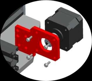
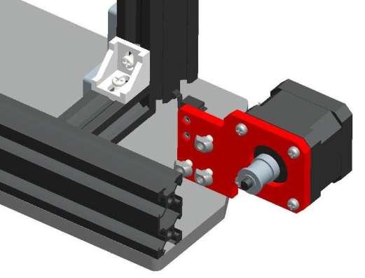
11 Step 5 Assemble Y axis Motor
12 Parts: 42 stepper motor 1pcs GT2-16 Pulley (with grub screw in it) 1pcs Limit switch 1pcs Y motor mount (Acrylic) 1pcs M3-8mm screws 4pcs M4-8mm screw 3pcs M4 T-Nut - 3pcs M2-10mm screw 2pcs M2 Nut 2pcs Insert the GT2-16 pulley to the motor shaft, tighten the grub screw in the pulley. Next assemble the 42 stepper motor and the Y motor mount(acrylic) with 4pcs M3-8mm screws. Secure the limit switch to motor mount using 2pcs M2-10mm screws and nuts. secure the motor mount to the back of the Y slide rail using 3pcs M4-8mm screws and T-nuts.

13
14 Step 6 Assemble Bed Frame
15 Parts: Bed frame (acrylic) 1pcs Wheel 3pcs Plastic pillar 3pcs M5-30mm- 3pcs M5 nut 3pcs GT2 Timing belt 1pcs Zip-ties 1pcs Secure the wheels in place using M5-30mm screws and nuts,using plastic pillar between wheel and bed frame. Tighten one end of the timing belt to the bed frame using a zip-ties. Next slide the base frame to the 2040 aluminium profile.


16
17 Step 7 Assemble Y-axis Belt Pulley


18 Parts: Y Pulley mount (acrylic) 1pcs Belt pulley 1pcs M5-25mm screw 1pcs M5 Nut 2pcs M6 washer 2pcs M5 washer 2pcs M4-8mm screw 3pcs M4 T-Nut - 3pcs Take 1pcs M5-25mm screw and insert the Pulley mount, secure it with M5 nut, then insert the washers and belt pulley, secure them using M5 nut. Secure the Y belt pulley assembly to the front of the Y slide rail using 3pcs M4-8mm screws and nuts. Tighten screws gently to avoid damaging the acrylic.
19 Step 8 Install Y axis Timing Belt
20 Parts: Zip-ties 1pcs Run the other end of timing belt along the aluminium profile, through the Y-GT2-16 Pulley and Belt pulley. Then tighten it to the bed frame using zip-ties as shown in the picture.


21
22 Step 9 Assemble Z Carriage
23 Parts: 2020 Aluminium profile 285mm 1pcs X-motor mount (acrylic) 1pcs Extruded bracket 1pcs Brass nut 1pcs Plastic pillar 6pcs Wheel 3pcs M5-40mm screw 3pcs M5 Locknut 3pcs M3-8mm screw 3pcs M4-8mm screw 2pcs M4 T-Nut - 2pcs Insert 3pcs M5-40mm screws to X-motor mount, and then scure it to the aluminium profile using 2pcs M4-8mm screws and T-nuts. Put the wheels into M5-40mm screws, using plastic pillars between wheel and acrylic, secure the Extruded bracket using M5 nuts. Place the brass nut on the extruded bracket, scure it using 3pcs M3-8mm screws.


24
25 Step 10 Install Z carriage
26 Parts: 42 stepper motor 1pcs GT2-16 Pulley (with grub screw in it) 1pcs M3-8mm screws 4pcs Carefully insert the X-axis assembly to the Z slide rail Insert the GT2-16 pulley to the motor shaft, tighten the grub screw in the pulley, then place the X stepper motor to the motor mount, secure them with 4pcs M3-8mm screws.


27
28 Step 11 Insert Extruder Assembly
29 Parts: Extruder assembly 1pcs Carefully insert the extruder assembly to the X slide rail.


30
31 Step 12 Assemble X axis Endstop & Pulley
32 Parts: Belt pulley 1pcs Limit switch 1pcs X Pulley mount (acrylic) 1pcs X endstop mount (acrylic) 1pcs M5-25mm screw 1pcs M5 Nut 1pcs M4-8mm screw 4pcs M5 Locknut 1pcs M4 T-Nut - 4pcs M6 washer 2pcs M2-10mm screw 2pcs M5 washer 2pcs M2 Nut 2pcs Secure the limit switch to X endstop mount using 2pcs M2-10mm screws and nuts. Then place the X endstop mount to the left end of the X slide rail using 2pcs M4-8mm screw and T-nuts. Take 1pcs M5-25mm screw and insert the Pulley mount, secure it with M5 nut, then insert the washers and belt pulley, secure them using M5 locknut. Secure the X belt pulley assembly on the right of the X slide rail using 2pcs M4-8mm screws and nuts.


33
34 Step 13 Install X axis Timing Belt

35 Parts: GT2 Timing belt 1pcs Zip-ties 2pcs Tighten one end of the timing belt to the belt hole using a zip-ties which back of the extruder Run the other end of timing belt along the aluminium profile, through the X-GT2-16 Pulley and Belt pulley. Then tighten it to another belt hole using a zip-ties, as shown in the picture.
36 Step 14 Assemble Z motor
37 Parts: 42 Stepper motor 1pcs Z-motor seat 1pcs Coupling (with grub screw in it) 1pcs Threaded rod 260mm 1pcs M3-8mm screw 4pcs M4-12mm screw 2pcs M4 T-Nut 2pcs Place 1pcs 42 stepper motor back of the Z slide rail, put the motor seat on the motor and then secure them with 4pcs M3-8mm screws. Install them to the Z slide rail using 2pcs M412mm screws and T-Nuts. Take 1pcs threaded rod through the brass nut,then insert to the coupling and tighten up.


38
39 Step 15 Install Filament Feeder


40 Parts: 42 Stepper motor 1pcs Feeding gear (with grub screw in it) 1pcs Extrution clip - 1pcs Extrution seat 1pcs M3-22mm 2pcs M3-16mm 1pcs M5-10mm Hex screw 1pcs Spring 1pcs Insert the feeding gear to the motor shaft and them tighten up. Place the Extrution seat and motor to the bracket as shown in the picture, secure them using 2pcs M3-22mm screws. Put one M5-10mm hex screw and spring between extrution clip and extrution seat, next secure the extrution clip with motor using M316mm screw.
41 Step 16 Install handle


42 Parts: Handle 1pcs Handle seat (Acrylic) 1pcs M5-10mm screw 2pcs M4-12mm screw 2pcs Put the handle seat on the top of Z slide rail, secure them with 2pcs M5-10mm screws. Secure the handle to the seat using 2pcs M4-12mm screws.
43 Step 17 Install Z endstop

44 Parts: Limit switch 1pcs Z endstop mount 1pcs M4-8mm screw 1pcs M4 T-Nut 1pcs M2-10mm screw 2pcs M2 Nut 2pcs Secure the limit switch to Z endstop mount using 2pcs M2-10mm screws and nuts. Place the Z endstop mount to the left Z slide rail, using one M4-8mm screw and T-nut.
45 Step 18 Assemble Print bed

46 Parts: Bed plate 1pcs M3-30mm screw 4pcs Thumb nut 4pcs Spring 4pcs Place the Bed plate on the bed frame use 4pcs springs between them, and then through 4pcs M3-30mm screws, then top 4pcs thumb nuts under the bed frame.
47 Step 19 Install Teflon hose
48 Parts: Teflon hose 1pcs Connector 1pcs Install a connector to the filament feeder, and then insert a teflon hose between feeder and extruder.

49
50 Step 20-1 Assemble Electronic Box
51 Parts: Electronic box bottom plate (acrylic) 1pcs Electronic box side plate 2pcs Mainboard 1pcs M3-20mm screws 6pcs M3 nuts 6pcs Plastic pillar 4pcs Place the mainboard on the bottom plate using M3-20mm and nuts, insert the plactic pillar between them. Assemble the side plates to the bottom plate as picture, secure them using M3-20mm screw&nut


52
53 Step 20-2 Assemble Electronic Box
54 Parts: Electronic box front plate 1pcs LCD display assembly 1pcs M3-20mm screws 4pcs M3 nuts 4pcs Assemble the front plate using M3-20mm screws and M3 nuts. Place the LCD display assembly to the box, using 2pcs M3-20mm screws and nuts.


55
56 Step 20-3 Assemble Electronic Box
57 Parts: Electronic box Back plate (left) 1pcs DC power jack 1pcs M3-20mm screws 1pcs M3 nuts 1pcs Assemble the back plate to the bottom plate as picture, secure them using M3-20mm screw&nut. Insert the DC power jack to the back plate.


58
59 Step 20-4 Assemble Electronic Box

60 Parts: Electronic box top plate 1pcs M3-20mm screws 3pcs M3 nuts 3pcs Cover the top plate using M3-20mm screws and M3 nuts.
61 Step 23 Control Board Wiring Diagram
62 Parts: Mainboard 1pcs The method of connecting wire is as picture There is only 1pcs cooler fan, please connect to CFAN on board There do not have heatbed and the thermistor, so there's no connection on Hotbed and BTEMP.

63 DC power jack x x
Step 1 Assemble Base Frame Parts: 2040 Aluminium profile 250mm 1pcs Base Plate 1pcs M4-8mm screw 3pcs M4 T-Nut 3pcs
 Step 1 Assemble Base Frame 2040 Aluminium profile 250mm 1pcs Base Plate 1pcs M4-8mm screw 3pcs M4 T-Nut 3pcs Put the aluminium profile on the base plate, secure them with 3pcs M4-10mm screws & T-Nut Step
Classification Of Screws
 Classification Of Screws M3 nuts 60pcs M3*20mm screws 58pcs M2.5*10mm black screws 2pcs M8 nuts 12pcs M3*10mm screws 17pcs M3*30mm screws 7pcs M8 Cushion ring 12pcs M3*14mm screws 4pcs Plastic Pillars
Part 7 Assembling the X axis
 Part 7 Assembling the X axis 1 2 The X axis is a key part of the printer, it carries the extruder on a carriage that moves the extruder laterally in the X axis. The x axis itself is moved vertically on
Code Product Qty 1 Top Vertex 3 2 Hot End Housing 1 3 Bottom Vertex 3 4 Print Platform Lock 3 5 End Stop Holder 3 6 Filament Feeder Motor Bracket 1 7
 List of Parts Code Product Qty 1 680mm Extrusion 3 2 Power Supply 1 3 240mm Extrusion 9 4 42mm Nema 17 Stepper Motor 3 5 Slider-Hotend Connecting Rod 6 6 48mm Nema 17 Stepper Motor 1 7 Linear Rail with
Delta Rostock mini G2& G2s Building instruction
 Delta Rostock mini G2& G2s Building instruction Safety Instructions ShenZhen GETECH CO.,LTD Building the printer will require a certain amount of physical dexterity, common sense and a thorough understanding
M2 Assembly. M2 Sub-Assemblies mm Belt Sub-Assembly mm Belt Sub-Assembly Spider Sub-Assembly... 4
 M2 Assembly Table of Contents M2 Sub-Assemblies... 3 630mm Belt Sub-Assembly... 3 702mm Belt Sub-Assembly... 3 Spider Sub-Assembly... 4 Idler Bolt Sub-Assembly... 8 Y Motor Sub-Assembly... 9 X Motor Sub-Assembly...
Kossel Rev B Build Guide V1.0
 Kossel Rev B Build Guide V1.0 1 Table of Contents: Step 1: BASE ASSEMBLY Gathering parts: Building the Corners and Base: Step 2: UPPER ASSEMBLY Building Upper: Step 3: VERTICAL RAIL INSTALLATION Building
BIGBOT ASSEMBLY INSTRUCTIONS. 1/18/2017 V0.5
 BIGBOT ASSEMBLY INSTRUCTIONS www.bigbot-3d.com 1/18/2017 V0.5 FOREWORD: PLEASE TAKE CARE WHEN HANDLING THE GANTRY. THE ASSEMBLY SHOULD BE HANDLED ONLY BY THE ALUMINUM FRAME, AND AVOID TOUCHING OR LIFTING
V4 Premium Kit. Prusa i3 Build Guide
 V4 Premium Kit Prusa i3 Build Guide Hi! Congratulations on your purchase of the DIYElectronics.co.za Prusa I3 kit, the best South African 3D Printer Kit! Hopefully this should serve as complete guide to
(Assembling Guide supplied by imakr ) with the support of MyMiniFactory.com
 with the support of MyMiniFactory.com") (Assembling Guide supplied by imakr ) with the support of MyMiniFactory.com Summary Congratulations on beginning on your journey into 3D printing with the STARTT 3D printer. In this guide, you will have
(Assembling Guide supplied by imakr ) with the support of MyMiniFactory.com Summary Congratulations on beginning on your journey into 3D printing with the STARTT 3D printer. In this guide, you will have
5. Extruder Assembly
 5. Extruder Assembly Guide for the assembly of the Extruder. Written By: Josef Prusa 2017 manual.prusa3d.com Page 1 of 22 Step 1 Get the necessary tools 2.5 and 1.5 mm Allen key Needle-nose pliers Step
Assemble Instruction of Geeetech Acrylic Prusa I3. pro C
 Assemble Instruction of Geeetech Acrylic Prusa I3 pro C Safety Instructions Shenzhen GETECH CO.,LTD Building the printer will require a certain amount of physical dexterity, common sense and a thorough
Assemble Instruction of Geeetech Acrylic. Prusa I3 Pro C
 Assemble Instruction of Geeetech Acrylic Prusa I3 Pro C Version 04-11-2016 Safety Instructions Building the printer will require a certain amount of physical dexterity, common sense and a thorough understanding
Assemble Instruction of Geeetech Acrylic Prusa I3. Pro & pro B
 Assemble Instruction of Geeetech Acrylic Prusa I3 Pro & pro B Version 04-11-2016 Safety Instructions Shenzhen GETECH CO.,LTD Building the printer will require a certain amount of physical dexterity, common
INVENT3D Printer Kit Disassembly Instructions
 INVENT3D Printer Kit Disassembly Instructions Version 6 AST2 10/26/16 1 I. General Disassembly Instructions Use the case layer drawings to ensure that components are stored in the appropriate location
Geeetech A30 3D Printer Building Instruction
 Geeetech A30 3D Printer Building Instruction Contents Safety Instructions... 1 Preparation... 2 1. Unfold the Box and Check the Package... 3 2. Assembly... 4 3. Wiring... 9 4. Warm Tips...16 Safety Instructions
AM8 Printer A metal frame for your Anet A8 By Pheneeny v1.0 April 20, 2017
 AM8 Printer A metal frame for your Anet A8 By Pheneeny v1.0 April 20, 2017 Please read this entire document before printing parts or building this frame Disclaimer: This guide is for informational purposes
Assembly Guide for Printrbot - Simple Maker s Edition 1405
 Assembly Guide for Printrbot - Simple Maker s Edition 1405 Last update: March 2016 Please Note: be careful on the steps that are underlined 1 Contents Tools Needed:... 3 First step: Check components and
Heacent 3D printer assembly manual. Prusa i3
 Heacent 3D printer assembly manual Prusa i3 Y-axis assembly 1. Y axis motor section: Find the belowing parts bag, Y-axis motor Assembled parts are separated as shown below, note that the motor between
LYMANBOT 3D PRINTER V3 Construction Manual
 LYMANBOT 3D PRINTER V3 Construction Manual Page 1 Read this whole Manual before starting to construct this Printer. User excepts all liability for the use of this Manual and the construction of this Printer.
The Portable Open Source 3D Printer
 http://web.archive.org/web/201502142011/http://www.tantillus.org/build_3.html Page 1 of 12 captures 12 Oct 12 - Feb 15 The Portable Open Source 3D Printer Home Start Case X/Y Axis Extruder Z Axis Electronics
Assembly Instructions. Beta Prusa DualX 3D Printer
 Assembly Instructions Beta Prusa DualX 3D Printer Version 2.6 Date Page 1 / 72 General data about the assembly instructions for an incomplete machine according to appendix VI of the EG machinery directive
4. Z-axis assembly. 4. Z-axis assembly. Written By: Josef Prusa manual.prusa3d.com Page 1 of 18
 4. Z-axis assembly Written By: Josef Prusa 2017 manual.prusa3d.com Page 1 of 18 Step 1 Get the necessary tools 13/17mm spanners 3.6mm flathead screwdriver Needle-nose pliers 2.5 and 1.5mm Allen key Step
Shenzhen GETECH CO.,LTD GEEETECH. Building Instructions of Geeetech Prusa I3 X
 Building Instructions of Geeetech Prusa I3 X CONTENT CONTENT... 2 Safety Instructions...3 Preparation...4 Unfold the box and check the package list... 5 1. Assemble the threaded rods of Y axis... 6 2.
SatNOGS. SatNOGS Rotator v3 Mechanical Assembly. This is the assembly guide for the third version of the SatNOGS Rotator.
 SatNOGS SatNOGS Rotator v3 Mechanical Assembly This is the assembly guide for the third version of the SatNOGS Rotator. Written By: Pierros Papadeas 2017 satnogs.dozuki.com Page 1 of 19 INTRODUCTION Notes:
Droplit v2 Frame Assembly
 SeeMeCNC Guides Droplit v2 Frame Assembly Droplit v2 Frame Assembly Written By: JJ Johnson 2017 seemecnc.dozuki.com Page 1 of 22 Step 1 Droplit v2 Frame Assembly Locate the Projector Plate, Projector Joining
Geeetech Delta Rostock mini G2 pro / G2s pro Building Instruction
 Geeetech Delta Rostock mini G2 pro / G2s pro Building Instruction (Document version: 04-11, 2016) CONTENT Safety Instructions... 1 Preparation... 2 1 Base Assembly... 3 1.1 Motor holder assembly... 3 1.2
Assembly Instructions Beta Prusa Standard & Deluxe
 Assembly Instructions Beta Prusa Standard & Deluxe 3D Printer Version 2.6 Date Page 1 / 67 General data about the assembly instructions for an incomplete machine according to appendix VI of the EG machinery
CNC Router Parts. Standard Rack & Pinion Drive Assembly Instructions
 CNC Router Parts Standard Rack & Pinion Drive Tools List The following tools will be used for assembly and installation of the Standard Rack & Pinion Drive: Imperial Allen Wrench Set - 3/32", 5/32", 3/16",
Lead Screw Upgrade. How to upgrade your ROBO R1 to the new Lead Screw Upgrade Pack. Written By: Harrison Team RoBo 3D
 Lead Screw Upgrade How to upgrade your ROBO R1 to the new Lead Screw Upgrade Pack. Written By: Harrison Team RoBo 3D 2017 guide.robo3d.com Page 1 of 14 Step 1 Lead Screw Upgrade Begin by powering off and
Assembly Instructions Beta Prusa Standard & Deluxe
 13/11/12 Assembly Instructions Beta Prusa Standard & Deluxe 3D Printer Version 1.0 Date 13/11/12 Page 1 / 66 General data about the assembly instructions for an incomplete machine according to appendix
Ender-3 3D Printer. Instructions for assembly
 Ender-3 3D Printer Instructions for assembly This guide is for the Ender-3 3D printer. Select the correct input voltage to match your local mains (220V or 110V). Because of software/hardware upgrades and
3. X-axis assembly. 3. X-axis assembly. Written By: Jakub Dolezal manual.prusa3d.com/ Page 1 of 13
 3. X-axis assembly Written By: Jakub Dolezal 2018 manual.prusa3d.com/ Page 1 of 13 Step 1 Tools necessary for this chapter Needle-nose pliers for zip tie trimming. 2.5mm Allen key for M3 screws 2mm Allen
Legacy Woodworking Machinery a division of Phantom Engineering. The Legacy CNC. Assembly Manual
 Legacy Woodworking Machinery a division of Phantom Engineering The Legacy CNC Assembly Manual New Orientation of the Legacy Step one: Re-orientation of the machine Remove the X-axis screw and supports.
re3d Assembling Gigabot: "Flatpack"
 re3d Assembling Gigabot: "Flatpack" Your Gigabot was assembled, calibrated, tested, and taken apart for shipping purposes. All you need to do is reassemble it, and you're ready to go! Written By: Chris
0. Disassembly. Disassembly of the MK2 printer and upgrading to the MK2S using the upgrade kit. Written By: Jakub Dolezal
 0. Disassembly Disassembly of the MK2 printer and upgrading to the MK2S using the upgrade kit. Written By: Jakub Dolezal 2018 manual.prusa3d.com/ Page 1 of 12 Step 1 Preparing the printer Ensure the printer
Written By: Brook Drumm
 Simple 1401 Assembly For kits produced between 1/15/14-6/1/14. This guide is for kits with the Fan Shroud. Instructions for metal and wood extruder (and bed) included below. Written By: Brook Drumm TOOLS:
Printrbot Simple (Model 1403) Rev F Printrboard
 Rev F Printrboard") Printrbot Simple (Model 1403) Rev F Printrboard Printrbot Simple is currently shipping with the Rev F Printrboard. Check which rev Printrboard your Simple kit includes and use the corresponding instructions.
Printrbot Simple (Model 1403) Rev F Printrboard Printrbot Simple is currently shipping with the Rev F Printrboard. Check which rev Printrboard your Simple kit includes and use the corresponding instructions.
F l a t S c r e e n A R M S I n s t a l l a t i o n
 ITEM NUMBERS (1) #TOACAORG16 (2) #TOACAORG20 (3) #TOACATRP24 (4) #TOACATRP30 (5) #TOACATRPDS (6) #TOACATRPSS TOOLS REQUIRED (1) 3/8 Wrench (not provided) (2) Phillips head screwdriver (not provided) (1)
OX CNC. Mechanical Assembly Instructions. S.A. Brown & Maker Store
 OX CNC Mechanical Assembly Instructions S.A. Brown & Maker Store v1.2 07 2017 Contents About The Maker Store Ox CNC Kit... 2 Unpack and Check All Components... 2 Tools Required... 2 Pre-Assembly Notes...
IMPORTANT SAFETY INSTRUCTIONS
 ASSEMBLY MANUAL IMPORTANT SAFETY INSTRUCTIONS! WARNING SHARP EDGES Use caution during assembly and operation of the 3D printer to ensure no sharp edges will cut you. Inspect the printer for any damage
535A. Main Components. Pipe and Bolt Threading Machine. Printed in U.S.A. Ridge Tool Company/Elyria, Ohio, U.S.A.
 Pipe and Bolt Threading Machine A Main Components 0 Screw, Button Head /" - 0 x /" () Washer, Flat /" ()" Top Cover 0 Base Bottom Cover Screw, Pan Head # - x " () Carriage Assembly 0 Front Support Bar
SECTION 9: PARTS. Table Breakdown REF PART # DESCRIPTION REF PART # DESCRIPTION
 SECTION 9: PARTS Table Breakdown 1 2 3 4 5 6 7 8 9 10 11 12 13 14 15 16 17 18 19 20 21 22 23 24 23 25 17 26 27 8 1 P0675001 CAP SCREW M8-1.25 X 30 15 P0675015 SUPPORT BLOCK 2 P0675002 TABLE SUPPORT BLOCK
Aluminum frame packing list of Smart Laser CO2
 Aluminum frame packing list of Smart Laser CO2 1 805mm V-slot 20mm*40mm 1 2 780mm V-slot 20mm*40mm 2 3 860mm Aluminum frame 20mm*40mm 3 4 177mm Aluminum frame 20mm*40mm 1 5 85mm Aluminum frame 20mm*40mm
HOME WORKSHOP HANDBOOK Rugged BENCH GRINDER. By JOEL B. LONG
 6 HOME WORKSHOP HANDBOOK Rugged BENCH GRINDER W By JOEL B. LONG ITH this bench grinder you can keep your cutting tools sharp and do general offhand grinding, and can, with the aid of various attachments,
SPARE PARTS LIST MODEL NO. LB1200F PAGE 1 ITEM PART NO. DESCRIPTION QTY NOTE
 PAGE 1 001 JM21000018 HEX.SOCKET HEAD SCREW M5X12 4 002 JM21000019 SPRING WASHER 5 4 003 JM21000020 FLAT WASHER 5 4 004 JM21000021 UP COVER COMPLETE 1 005 JM21000025 MICRO SWITCH FIX PANEL A 1 006 JM21000026
Welcome! Table of Contents
 Welcome! The folks at Random Idea Generator Shop would like to thank you for purchasing our 3D printer kit. We are dedicated to providing an easy to build kit with customizable options to meet your requirements.
Procedure 5: Hammer Bank Removal
 T6215 Maintenance Manual Procedure 5: Hammer Bank Removal The Hammer Driver CBA has components which are static sensitive! Use the appropriate ESD grounding procedures when handling the Hammer Bank Assembly.
CNC Router Parts PRO Machine Kit Cable Track Installation Instructions
 1 1 X CABLE TRACK TRAYS & BRACKETS The cable track on the side of the system is supported by a metal tray (or multiple trays for longer systems such as a PRO4896). These trays hang from brackets on the
Wanhao D9. Assembly and installation manual. This work is licensed under a Creative Commons Attribution 4.0 International License.
 Wanhao D9 Assembly and installation manual This work is licensed under a Creative Commons Attribution 4.0 International License. Table of Contents Introduction 2 Compatibility 2 What s in the box? 2 Raise3D
Geeetech Acrylic I3 Pro C 3D Printer
 Geeetech Acrylic I3 Pro C 3D Printer Copyright Declaration The copyright of this manual belongs to the Shenzhen GETECH CO., LTD. (hereinafter referred to as the "Geeetech"), and all rights reserved. No
SECTION 9: PARTS. Electrical REF PART # DESCRIPTION REF PART # DESCRIPTION
 SECTION 9: PARTS Electrical 1 P4002001 START BUTTON 52 P4002052 CONTACTOR GSC1CJX4-D 110V 2 P4002002 INDICATOR LIGHT 53 P4002053 CONTACTOR JZC3-40D 110V 3 P4002003 JOG BUTTON 54 P4002054 FUSE HOLDER 4
ABM International, Inc. Navigator Assembly Manual
 ABM International, Inc. 1 1.0: Parts List Tablet (Qty. 1) Tablet mount (Qty. 1) NOTE: Mount may appear and operate different then image below Control Box (Qty. 1) Motor Power Supply (Qty. 1) 2 X-axis motor
Assembly Instructions
 P/N 8650/8655 Assembly Instructions NOTE: Your Sherline CNC Cam Grinder is double boxed and secured to a wooden shipping frame. Upon delivery, check the outer box for damage. If the box is damaged, take
3D PRINTER. Pack 11. Anything you can imagine, you can make! 3D technology is now available for you at home! BUILD YOUR OWN
 BUILD YOUR OWN Pack 11 Anything you can imagine, you can make! 3D PRINTER Compatible with Windows 7 & 8 Mac OS X 3D technology is now available for you at home! BUILD YOUR OWN 3D PRINTER CONTENTS PACK
AndyMark DART 12.
 AndyMark DART 12 Part Number Description QTY These Parts Are Pre-Assembled by AndyMark am-0031 Bearing, 3/16"ID (R3) 1 am-0209 Bearing, 3/8"ID 1614ZZ 2 am-1028 Screw, #10-32x3/8 Pan Head Philips 8 am-1121
Shapeoko XXL Assembly Guide
 Shapeoko XXL Assembly Guide 04/27/2016 XXL Packing LIst Item Qty Description Y-Carriage (left) 1 Y-Carriage (right) 1 X/Z Assembly 1 40 Rail 3 1 rail has mounting holes for controller Wasteboard Half 2
Riverside. Windhaven Queen Storage Bed Assembly Instructions
 Queen Storage Bed Page 1 of 7 2 pcs. 4 pcs. 4 pcs. 4 pcs. 2 pcs. 5/0 Queen Storage Bed 50773 -- 5/0 Storage Footboard w/platform Note: The 50773 Storage Footboard can be used with the 50770 Panel Headboard
Intercooler Shroud and Belt Cover for WRX
 Intercooler Shroud and Belt Cover for 2015+ WRX 2016-05-18 Thank you for purchasing this PERRIN product for your car! Installation of this product should only be performed by persons experienced with installation
25-200H. 12 Planer / Jointer. with Helical Cutterhead. Parts List.
 25-200H 12 Planer / Jointer with Helical Cutterhead 4001824 Parts List www.rikontools.com CABINET ASSEMBLY PARTS EXPLOSION & PARTS LIST KEY NO. DESCRIPTION KEY NO. DESCRIPTION 1 Pan Head Screw M6x12 P25-200H-1
ELECTRICAL CARGO BIKE with mechanical disc breaks
 ELECTRICAL CARGO BIKE with mechanical disc breaks SAMLEMANUAL ASSEMBLE MANUAL Read and understand these instructions before you begin the assembly. The bike comes partly assembled, and it is important
Riverside. Harbor Hill Queen Storage Bed Assembly Instructions
 Queen Storage Bed Page 1 of 7 8 pcs. 8 pcs. 1 pc. 2 pcs. 3 pcs. 3 pcs. 4 pcs. 4 pcs. 4 pcs. 1 pc. 1 pc. 8 pcs. 8 pcs. 8 pcs. 2 pcs. 8 pcs. 1 pc. 25770 -- 4/6-5/0 Panel Headboard (NOTE: the 25775 Leather
Table of Contents CONTENTS
 Table of Contents CONTENTS Introduction... 2 Contact TKI... 2 Printer Features & Definitions... 3 Software Parameter Setup... 8 Setting Up A Printer Profile in Cura... 8 Printing Settings... 13 Printing
SS1062, SS10621 & SS10621E Free Standing PWC & Fishing Boat Hoist SS1062 SS10621 SS10621E
 SS1062, SS10621 & SS10621E Free Standing PWC & Fishing Boat Hoist SS1062 SS10621 SS10621E Midwest Industries, Inc. Page 1 Ida Grove, IA 51445 800.859.3028 www.shorestation.com 0003231 REV A 1/25/05 Bundles
Assembly Instructions
 Assembly Instructions Note: Prior to assembly, be sure to remove all printing pads from the printed parts and also be sure to sort through and organize all of your hardware before assembly this will help
Riverside. Harbor Hill King Storage Bed Assembly Instructions
 King Storage Bed Page 1 of 7 8 pcs. 8 pcs. 1 pc. 2 pcs. 6 pcs. 3 pcs. 4 pcs. 4 pcs. 4 pcs. 1 pc. 1 pc. 2 pcs. 8 pcs. 8 pcs. 8 pcs. 8 pcs. 25780 -- 6/0-6/6 Panel Headboard (NOTE: the 25785 Leather Headboard
Riverside. Oakmont Queen Storage Bed Assembly Instructions
 Queen Storage Bed Page 1 of 7 8 pcs. 8 pcs. 1 pc. 1 pc. 8 pcs. 8 pcs. 8 pcs. 8 pcs. 1 pc. 1 pc. 20270 --5/0 Sleigh Headboard 20274 --5/0-6/6 Bed Rails 20273 -- 5/0 Storage Footboard, Panels, Slats Queen
Document version: 1.1. Beagle Build manual
 Document version: 1.1 Beagle Build manual TABLE OF CONTENTS Table of contents...2 About the Beagle...3 Change history...4 Safety warnings...4 Required tools...5 1. Bars & Printed parts examination...6
SECTION 9: PARTS. Main Breakdown -36- Model G5394 (Mfd. Since 11/08)
") SECTION 9: PARTS Main Breakdown 105 137 136 113-1 113 141 140 113-2 113-3 111 113-4 114 135 143 144 101 121-1 -1 116 147-1 121-2 115 120 121 107 108 164 162 160 158 138 109 127 126 160 158 123 127 123
SECTION 9: PARTS Main Breakdown 105 137 136 113-1 113 141 140 113-2 113-3 111 113-4 114 135 143 144 101 121-1 -1 116 147-1 121-2 115 120 121 107 108 164 162 160 158 138 109 127 126 160 158 123 127 123
This manual will aid in the assembly of the FireBall V90 and FireBall X90. The assembly of both machines will be identical, unless specified.
 This manual will aid in the assembly of the FireBall V90 and FireBall X90. The assembly of both machines will be identical, unless specified. Step #1 Lay all parts out to verify quantities. (2) 2 x 25-1/4
INSTALLATION INSTRUCTIONS
 Do not attempt to install this product on any vehicle other than the one it is designed for and listed above! Parts List 10 3/8 X 1 1/4 Hex Bolt 10 3/8 Lock Washer 4 3/8 Hex Nut 4 3/8 Flat Washer 2 3169)
Titan Aero Assembly. Titan Aero Assembly. Learn to assemble your Titan Aero. Written By: Gabe S e3d-online.dozuki.
 Titan Aero Assembly Learn to assemble your Titan Aero Written By: Gabe S. 2018 e3d-online.dozuki.com/ Page 1 of 26 INTRODUCTION The Titan Aero is a very similar build to a Titan and a V6 put together (which
MODEL NO.: MI PARTS BREAKDOWN
 MODEL NO.: MI-76350 PARTS BREAKDOWN MAGNUM DRILL PRESS ASSEMBLY INSTRUCTIONS MODEL MI-76350 Before you begin to assemble your drill press, review the parts breakdown and keep it ready for reference. Start
firepickdelta Assembling the Frame Instructions for the assembling the frame for the FPD. Written By: Neil Jansen
 firepickdelta Assembling the Frame Instructions for the assembling the frame for the FPD. Written By: Neil Jansen 2017 firepickdelta.dozuki.com Page 1 of 10 INTRODUCTION Inventory your parts first and
INSTALLATION INSTRUCTIONS KK-K9-F14-K K9 KIT FOR FORD EXPEDITION
 INSTALLATION INSTRUCTIONS KK-K9-F14-K-32 32 K9 KIT FOR 2003-2016 FORD EXPEDITION TOOLS REQUIRED: Power Drill Drill Bit Set Standard & Metric Socket Sets Phillips Screw Driver Open End Wrench Set Wire Cutters
Inspiration taken from Reprap Mendel Sketchup Model by Capo: om/3dwarehous e/details? mid=86dc5e3cc ad914839c51e370
 Goal: Provide a visual guide of the steps needed to construct a Prusa Mendel Printer. The instructions contained within are copied verbatim from the reprap.org wiki: http://reprap.org/wiki/prusa as of
Fan, Eden/Northfield, GS Installation Instructions (SKU ) Packing List
 Packing List") Packing List Blower Assembly Wiring Harness Rheostat with Nut and Knob Snap Disc Mounting Hardware (4) rubber grommets with brass inserts, (4) nuts, (4) washers. Cover Assembly Installation Warning: Make
Packing List Blower Assembly Wiring Harness Rheostat with Nut and Knob Snap Disc Mounting Hardware (4) rubber grommets with brass inserts, (4) nuts, (4) washers. Cover Assembly Installation Warning: Make
Customers should turn off the machine with the power cable and USB data cable pulled down from it when installing or removing extruder.
 INSTALLATION &REMOVAL of the EXTURDER Customers should turn off the machine with the power cable and USB data cable pulled down from it when installing or removing extruder. I.How to disassemble the extruder
User Instructions Multiline Otter Scoreboard Caddy Assembly
 List of parts: User Instructions Multiline Otter Scoreboard Caddy Assembly Single Caddy Double Caddy 1 1 Base assembly with attached wheels 2 4 1 1 2 4 4 8 10 20 12 Uprights (60 or 74 aluminum extrusion)
Depending on the size you ordered you will have either 5 Foot sections which will build the 10 Foot frame or 6 Foot sections which will build the 12
 XL Quilting Frame 1 Depending on the size you ordered you will have either 5 Foot sections which will build the 10 Foot frame or 6 Foot sections which will build the 12 Foot frame Printed 2 June 2014 Updated
SECTION 9: PARTS Cabinet & Base
 SECTION 9: PARTS 5 5-1 48 3 75 90 49 4 91 333 46 47 30 89 88 2 34 33 37 36 78 35 32 326 316 49 42 45 83 84V2 43 1 7 8 9 12 87 10 11 Cabinet & Base 31 17 20 40 39 136 41 135 85 86 8 28 26 18 19 21 19 370
HYDRAULIC CONTROL DETAILS PARTS LIST
 Always give model number, serial number and part number when ordering repair parts. HYDRAULIC CONTROL DETAILS PARTS LIST REF NO. PART NUMBER DESCRIPTION 1 101939 Hydraulic Tank 2 101940 Hydraulic Tank
Z 406 Bench work Manual
 08686 Z 406 Bench work Manual Rev A Custodian: Brian Simeone Table of Contents Section Gantry Removal & Replacements Page 1.. Remove & Replace Printer Module.......3 2.. Remove & Replace Head Card Assembly.....
N. 15th Street, Middlesboro, KY FLIP TARP DUMP BODY INSTALLATION INSTRUCTIONS
 1-800-248-7717 1002 N. 15th Street, Middlesboro, KY 40965 FLIP TARP DUMP BODY INSTALLATION INSTRUCTIONS Congratulations on your purchase of a Mountain Flip Tarp Dump Body tarping system. With tarping systems
Exploded View Saw Base - Model 7060 Semi-Automatic Cut-Off Band Saw
 Exploded View Saw Base - Model 7060 Semi-Automatic Cut-Off Band Saw 136 137 135 134 132 131 133 113 114 115 117 116 118 119 120 121 79 78 77 107 108 65 76 110 109 66 10 9 6 11 5 4 8 7 75 74 73 72 111 112
JK Spartacus Stamped Front Bumper
 Page 1/14 OMIX-ADA TECHNICAL SUPPORT PHONE: M-F 8am - 5pm EST 1-800-449-6649 EMAIL: techsupport@omix-ada.com FOR WARRANTY INFORMATION VISIT: www.omix-ada.com Page 2/14 Part #11544.01 11544.09 11543.13
READ THIS FIRST. For questions or help with this product contact Tech Support at (570) or
 or") READ THIS FIRST Model G4002/G4003 ***IMPORTANT UPDATE*** For Machines Mfd. Since December, 2014 and Owner's Manual Printed April, 2014 For questions or help with this product contact Tech Support at (570)
READ THIS FIRST Model G4002/G4003 ***IMPORTANT UPDATE*** For Machines Mfd. Since December, 2014 and Owner's Manual Printed April, 2014 For questions or help with this product contact Tech Support at (570)
Removing outter components
 Y Axis Motor Replacement Replacing the Y axis motor is a process that requires the individual to be somewhat mechanically inclined and can follow detailed instructions. If any of the following steps are
ACTUATOR KIT. Assembly Instructions. for 300mm, 500mm and 1000mm kits. S.A. Brown & Maker Store. v1.
 ACTUATOR KIT Assembly Instructions for 300mm, 500mm and 1000mm kits S.A. Brown & Maker Store v1.0 12 2016 www.makerstore.com.au Contents About The Maker Store Actuator Kit... 2 Unpack and Check All Components...
Main Drive Components
 Pipe and Bolt Threading Machine Main Drive Components 0 0 Rear Centering Head Centering Jaw Set Spiral Pins () 00 Centering Scroll Retaining Ring 0 Rear Bearing 0 Oil Ball Valve () # - x / Screw Motor
Removing the Z-Axis lead screw
 Page 1 of 8 TITLE: Sabre Z-Axis Lead Screw Replacement Procedure Gerber FastFact #: 5048 Supplied by: Gerber Hardware Support Last Modified: June 14, 2007 Summary: Tools used: The following procedure explains
Assembly Instructions
 Assembly Instructions Note: Prior to assembly, be sure to remove all printing pads from the printed parts and also be sure to sort through and organize all of your hardware before assembly this will help
Mostly Printed CNC Assembly Instructions
 Index 0 Calculate the length of your conduits, belts, etc.... 2 Conduits... 2 Belts... 2 All-thread... 2 1 Parts you need... 2 Unit-independent... 3 Imperial... 3 Metric... 3 2 Part preparation... 4 4x
Print Head Installation Guide
 Print Head Installation Guide MCS Raptor 6 (MCS Eagle AMS Software) is copyright of MCS Incorporated. 2015 MCS Incorporated. 1 Contents Tools... 4 Warnings... 4 Introduction... 4 Section One - Pillar Installation...
Replacing a Wheel on the Pinch Wheel assembly
 14140 NE 200th St - Woodinville, WA. 98072 - PH: (425) 398-8282 - Fax: (425) 398-8383 Replacing a Wheel on the Pinch Wheel assembly Determine which pinch wheel assembly your plotter or cutter has. See
40670 Transit Connect/NV200/City Express/ProMaster City Partition
 40670 Transit Connect/NV200/City Express/ProMaster City Partition Top Panel (1) Bottom Panel (1) Transit Connect (2014) Top Angle (1) TC Top MNT BRKT (2) TC Bottom MNT PLT (2) NV200/City Express Top Mount
WASP Extended Shuttle Fitting. Process Overview
 Process Overview Tools needed; metric Hex key set Remove Wasp Plate sealer from all power and pneumatic supplies; situate the unit on a clear work area for access. Ensure the Wasp plate sealer has cooled
F i t t i n g t h e N e w L a n d i n g G e a r t o Y o u r S k y J i b V 1
 F i t t i n g t h e N e w L a n d i n g G e a r t o Y o u r S k y J i b V 1 1 P a r t s L i s t : S t a n d a r d L a n d i n g G e a r U p g r a d e Product Code Parts + Spares Product Code Parts + Spares
Note: Parts without part numbers are for reference only and cannot be purchased individually.
 Parts Ordering Replacement Parts To order parts or reach our service department, call 1-800-274-6848 between 7:30am and 5:30pm (CST), Monday through Friday. Having the Model Number and Serial Number of
Record the serial number and date of purchase in your manual for future reference.
 10 Woodworking Bandsaw Model: 10-305 Parts List Record the serial number and date of purchase in your manual for future reference. Serial number: Date of purchase: Part # 10-305PL1 For more information: