HOME WORKSHOP HANDBOOK Rugged BENCH GRINDER. By JOEL B. LONG
|
|
|
- Erick Hill
- 5 years ago
- Views:
Transcription

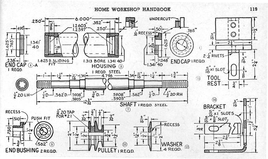
1 6 HOME WORKSHOP HANDBOOK Rugged BENCH GRINDER W By JOEL B. LONG ITH this bench grinder you can keep your cutting tools sharp and do general offhand grinding, and can, with the aid of various attachments, perform such other operations as wire brushing, buffing, polishing, sanding, and drilling. Anyone having a bench lathe and drill press should have no trouble in building it. First, study drawings especially those showing the spindle assembly of the shaft and housing drawings (Parts #3 and 7). Make up the patterns for the castings required, using measurements given on the prints. Cast base solid if you wish. Add about /6 in. for machining where facing is indicated on the print. Make frame and base of aluminum. The castings are shown in Fig.. Chuck the base (#8), in the 4-jaw chuck (Fig. 2) and take a facing cut across the top until smooth. Reverse casting and face the bottom. To bore out the frame (#), that holds the spindle housing mount the casting on a home made angle plate fixture that fits on the tool post (Fig. 3). Note that the lower lathe swivel is turned around on the carriage to provide room to mount casting. Use a boring bar supported between centers and having an adjustable cutter; make, if one is not available. Bring hole to size (.625) by taking light cuts and fine feeds and by adjusting the cutter bit after each cut is made. Remove from fixture and, holding casting in vise, carefully saw through its entire length with a hacksaw (Fig. 4). Drill the 2 holes shown with a

 then bore out the hole (Fig. 6) to within.020. Use finished housing for a gage for a snug fit.")
. Drill holes with #7 drill and tap ¼-20 NC.")

2 HOME WORKSHOP HANDBOOK 7 No. 7 drill and tap them ¼-20 NC. Turn a stub mandrel by chucking up a piece of scrap rod. Without removing from chuck, mount the frame on this and tighten the two screws which will hold it securely by closing the slot. Support outer end of mandrel with tail stock center. Now true up the ends and bring casting to 4 in. length (Fig. 5). Use the 3-jaw chuck to hold the belt guard casting (#0), with large part in. Take a light truing cut on the extension. Reverse the casting and chuck it by the extension. Face it to length (2½ in.) then bore out the hole (Fig. 6) to within.020. Use finished housing for a gage for a snug fit. Finish guard, bringing it to size. Machine the large wheel guard (#9), boring the hole to within.020 of the dia. After the inside of the large section is machined, mount the guard on a mandrel and true it up by taking a cut (Fig. 7). Drill holes with #7 drill and tap ¼-20 NC. for the set screws in both guards. Build the tool rest (#5), and the bracket (#6). Mill clean slots in the bracket by holding it in the milling attachment and using a 5/6 in. mill end having 4 flutes, as shown in Fig. 8. Position frame on the base and drill and tap holes where shown for the 4 screws. Clean the frame and base with a file and fine emery cloth. On the shaft (#7), be careful to get the exact measurements. Your finished job will be no better than the accuracy of the shaft assembly (Figs. 9 and 0). Use in. dia. drill rod 2¼


3 8 HOME WORKSHOP HANDBOOK long for the spindle or a piece of cold rolled steel. Cut to length, center drill each end and mount between centers. Bring shaft to exact dimensions, getting an exact fit on the bearing surfaces. Use very light finishing cuts with a freshly honed cutter with slow feed. Use the bearing itself as a gage, The finished shaft assembly is shown in Fig. 0. Next, make the shaft housing (#3), to hold the sealed bearings. Chuck the tube in the 4-jaw chuck and center it dead true. Use a dial indicator if one is available, or center it by trying it for fit until you bring the bearing surfaces to exact size for a push fit. Now, thread the ends. Be sure centers are true before you start. Cut right hand threads with carriage feed toward the headstock and compound set at an angle of 29 to the right as you face the lathe. Cut left hand threads with feed away from headstock and compound set 29 to the left. If your experience in screw thread cutting is limited, first consult your lathe manual on this operation and practice cutting some threads on a piece of scrap. In cutting the threads, grind a cutter bit to 60 angle or use a formed cutter (Fig. 9). Try the nuts for correct fit as you proceed. If you have a tool post grinder, grind the shaft all over and do a beautiful job. MATERIALS LIST 6 BENCH GRINDER Pc. No. Name Material No. Reqd. Frame Alum. 2 ¼-20 fill. hd. screws, Ig Steel 6 3 Housing, 5/8 O.D., /8 I.D. 4 End cap (pulley) 4 A 5 End cap (wheel) End bushings 2 6 Ball bearings (77-3L02 N.D) 2 7 Shaft 8 Base Alum. 9 Wheel guard 0 Belt guard Pulley Steel 2 Washers 4 3 ½-20 R. H. nut 4 ½-20 L.H. nut 5 Tool rest 6 Tool rest bracket 7 5/6 nut, bolt & washer (for #6 & #5) 8 ¼ 20 hex. hd. screws ¾ lg. (for #8 & #6) 2 9 ¼ 20 headless set screw (for #0) 20 ¼ 20 headless set screw (for #9) 2 ¼ 20 headless set screw (for #)
4
. This will give a true surface for your center rest to seat against. Now set up the center rest and then bore out the housing to dimensions given.")

5 adjusting the jaws individually. After centering you will have a run out of a few thousandths on the free end, so with a very sharp cutter take a light cut and true up housing for about one in. (about.005 will be removed). This will give a true surface for your center rest to seat against. Now set up the center rest and then bore out the housing to dimensions given. As bearing recess must be an exact fit for the bearing use bearing as a gage until you get a push fit into recess. Next, face housing end true and smooth. Now thread the tube for the end cap. Transpose the gears to cut the internal threads 40 threads per inch and set the 60 cutter point on exact center. Use a heavy boring bar, then, to hold the cutter bit. Cut the threads to the correct depth given on thread gage or chart. Do not cut the threads without first making the undercut or groove as shown. This enables you to stop the cut without trouble. After threading one end, reverse the tube in chuck, take the truing-up cut as before and adjust center rest. Face end, bring tube to exact length, and then bore out tube or housing. Cut threads as outlined above. Turn the end caps, Pt. 4, from solid bar stock or aluminum while held in the 3-jaw chuck. Finish to measurements shown, bore the hole and thread the end, bringing threads to proper depth. Use screw thread gage on threaded housing to try for fit as you go along. Complete the job, then cut off with the cut-off tool to exact length. Turn the end bushings (#5), the pulley (#), and the washers (#2), from aluminum, steel or brass. With the shaft housing completed, rechuck the large and small guards and finish boring the holes to correct size for a slide fit over the shaft housing. Use the housing as a gage for the hole diameter. Set screws will hold the guards securely on the housing. Now for assembly. If you have followed the measurements closely, the shaft, when installed, should have no play or bind and should be free running. Drill 5/6 in. holes in base for the hold down screws or bolts. Also, drill and tap holes for screws that hold the tool rest bracket. Clean and polish base and frame and apply a coat or two of machinery enamel.
By C.W. Woodson From the pages of Model Craftsman magazine June, 1937
 By C.W. Woodson From the pages of Model Craftsman magazine June, 1937 As shown in Fig. 1, the tool post grinder for which plans are given here can be used to finish up delicate work to more accurate dimensions
Lathes. CADD SPHERE Place for innovation Introduction
 Lathes Introduction Lathe is one of the most versatile and widely used machine tools all over the world. It is commonly known as the mother of all other machine tool. The main function of a lathe is to
SECTION 9: PARTS. Electrical REF PART # DESCRIPTION REF PART # DESCRIPTION
 SECTION 9: PARTS Electrical 1 P4002001 START BUTTON 52 P4002052 CONTACTOR GSC1CJX4-D 110V 2 P4002002 INDICATOR LIGHT 53 P4002053 CONTACTOR JZC3-40D 110V 3 P4002003 JOG BUTTON 54 P4002054 FUSE HOLDER 4
Turning and Lathe Basics
 Training Objectives After watching the video and reviewing this printed material, the viewer will gain knowledge and understanding of lathe principles and be able to identify the basic tools and techniques
Tool & Cutter Grinder
 Tool & Cutter Grinder The Bonelle Tool and Cutter grinder (based on prof. Chaddock s Quorn) can be used to grind most kind of tools from lathe tools to end-mills and reamers. I have been grinding my end-mills
READ THIS FIRST. For questions or help with this product contact Tech Support at (570) or
 or") READ THIS FIRST Model G4002/G4003 ***IMPORTANT UPDATE*** For Machines Mfd. Since December, 2014 and Owner's Manual Printed April, 2014 For questions or help with this product contact Tech Support at (570)
READ THIS FIRST Model G4002/G4003 ***IMPORTANT UPDATE*** For Machines Mfd. Since December, 2014 and Owner's Manual Printed April, 2014 For questions or help with this product contact Tech Support at (570)
Lathe Accessories. Work-holding, -supporting, and driving devices
 46-1 Lathe Accessories Divided into two categories Work-holding, -supporting, and driving devices Lathe centers, chucks, faceplates Mandrels, steady and follower rests Lathe dogs, drive plates Cutting-tool-holding
Looking for a small band saw? The Ellis 1100 band saw might be just what you are looking for.
 1100 MITRE BAND SAW Looking for a small band saw? The Ellis 1100 band saw might be just what you are looking for. This portable band saw moves easily to the job site. Use it as horizontal or vertical saw.
I FOOT. ={Li..W---- r"-l, : I t- JJl --, : I: +- y1a'_' L 1~6~'1. ' +-+-'-f' <~,~ ::-,-~,~-~--f~:,~::-~%r
 1hz" 3/Is"m.p.1. +--1---4+ ; ttf. I I, /~ 'r-- - - - - - - - - - - -1-11--- -- ---(~/-+--':.r--+~ ' +-+-'-f'
Cross Peen Hammer. Introduction. Lesson Objectives. Assumptions
 Introduction In this activity plan students will develop various machining and metalworking skills by building a two-piece steel hammer. This project will introduce basic operations for initial familiarization
SECTION 9: PARTS. Headstock A 126A 127A-1 REF PART # DESCRIPTION REF PART # DESCRIPTION
 SECTION 9: PARTS Headstock 120 121 113 115 112 111 110 109 108 105 106 107 135 101 119A 121 120 118 114 115 107 106 104 123 122 118 114 126A 105 126 103 102 126B 127A-1 131 127A 124 133 134 126C 129 130
Machine Your Fishing Reel
 Machine Your Fishing Reel You will be well prepared for the coming season if you start on this smooth-running job now. IF you're an enthusiastic fisherman and have a lathe in your workshop, we'll say no
MINI-LATHE QUICK CHANGE TOOL POST
 MINI-LATHE QUICK CHANGE TOOL POST Cutting and assembly details Machinists should familiarize themselves with the contents of this section before jumping in to the drawings. Many details are described here
Build a Drill Press Vise
 Youth Explore Trades Skills Introduction This activity plan will develop the student s machining and metalworking skills as they fabricate a multi-piece steel vise. The project will encompass basic lathe
V twin cylinder steam engine
 V twin cylinder steam engine I got inspired to make this V twin steam engine after reading R. Griffinn s build articles in ME 4396. It is based on Stuart s V-twin double-acting oscillator, but since I
Lathe. A Lathe. Photo by Curt Newton
 Lathe Photo by Curt Newton A Lathe Labeled Photograph Description Choosing a Cutting Tool Installing a Cutting Tool Positioning the Tool Feed, Speed, and Depth of Cut Turning Facing Parting Drilling Boring
7x --Tailstock Cam Lock
 7x --Tailstock Cam Lock By Magic Brian magicbrian40@yahoo.com Probably the most pleasing mod to have, but often not done through lack of milling facility s This version does NOT require a mill. MATERIALS
Building a vertical wobbler
 Building a vertical wobbler I wanted to build a simple steam engine that would also run on compressed air. At Chris Heapy s website (http://easyweb.easynet.co.uk) I found drawings of a small double acting
CARIBBEAN EXAMINATIONS SECONDARY EDUCATION CERTIFICATE EXAMINATION MECHANICAL ENGINEERING TECHNOLOGY. Paper 02 - Technical Proficiency.
 FORM TP 2011094 CARIBBEAN EXAMINATIONS SECONDARY EDUCATION CERTIFICATE EXAMINATION TEST CODE 01335020 COUNCIL MECHANICAL ENGINEERING TECHNOLOGY Paper 02 - Technical Proficiency 2'h hours MAY/JUNE 2011
SECTION 10: PARTS. Headstock
 33 32 31 30 7 SECTION 10: PARTS 34 23 36 22 15 14 12 35 37 48 39 41 42 50 40 25 38 38 26 39 42 44 41 25 26 40 51 43 52 10 5 53 9 4 1 27 2 21 19 20 Headstock 8 16 11 17 18 14 13 7 6 45 47 46 3 1 P0768001
 DEPARTMENT OF MECHANICAL ENGINEERING QUESTION BANK ME6402 MANUFACTURING TECHNOLOGY II UNIT I PART A 1. List the various metal removal processes? 2. How chip formation occurs in metal cutting? 3. What is
" Tiller Attachment (1993) Page 1 of 5 Chain Case Assembly
 Page 1 of 5 Chain Case Assembly") 190-766-190 38" (1993) Page 1 of 5 Chain Case Assembly 190-766-190 38" (1993) Page 2 of 5 Chain Case Assembly 04991 1 Chain Case Assembly 1 05034 1 S Bearing Housing 1.375" Dia. 2 14895 1 S Housing Assembly
190-766-190 38" (1993) Page 1 of 5 Chain Case Assembly 190-766-190 38" (1993) Page 2 of 5 Chain Case Assembly 04991 1 Chain Case Assembly 1 05034 1 S Bearing Housing 1.375" Dia. 2 14895 1 S Housing Assembly
SECTION 10: PARTS. Headstock
 33 32 31 30 7 SECTION 10: PARTS 34 23 36 22 15 14 12 35 37 48 39 41 42 50 40 25 38 38 26 39 42 44 41 25 26 40 51 43 52 10 5 53 9 4 1 27 2 21 19 20 Headstock 8 16 11 17 18 14 13 7 6 45 47 46 3 1 P0768001
Travis Bishop. Submitted to: Dr. John Davis. Date: 3 December Course: ETME 310 Section: 004. Lab Topic: Milling Project (Vise)
") Travis Bishop Submitted to: Dr. John Davis Date: 3 December 2012 Course: ETME 310 Section: 004 Lab Topic: Milling Project (Vise) Introduction: Purpose of Experiment: This experiment was conducted to teach
Travis Bishop Submitted to: Dr. John Davis Date: 3 December 2012 Course: ETME 310 Section: 004 Lab Topic: Milling Project (Vise) Introduction: Purpose of Experiment: This experiment was conducted to teach
Introduction to Machining: Lathe Operation
 Introduction to Machining: Lathe Operation Lathe Operation Lathe The purpose of a lathe is to rotate a part against a tool whose position it controls. It is useful for fabricating parts and/or features
SECTION 9: PARTS Main
 -64- Model G0765 (Mfd. Since 5/15) 1 2 3 4 5 6 7 8 9 9 10 10 11 11 12 12 13 14 15 16 17 18 19 20 21 21 22 23 23 24 25 26 27 28 29 30 31 32 33 35 36 37 38 39 40 41 42 43 44 44 45 157 46 47 48 49 50 50 51
M1014 7" x 12" Metal Cutting Bandsaw PARTS -38-
 14 13 15 16 18 17 55 10 12 11 19 54 9 20 53 7 5 4 60 7 3 1 28 6 2 61 23 27 26 29 21 24 25 22 32 32 33 35 36 37 38 49 48 47 40 39 34 30 59 51 52 46 45 44 43 42 42 41 50 56 57 58-38- Parts List 1 XM1014001
BUILD YOUR OWN MACHINE TOOLS CASTINGS
 BUILD YOUR OWN MACHINE TOOLS CASTINGS We Supply The LATHES - SHAPERS - MILLING MACHINES No. 2 Bench Milling Machine with Overarm Constructed From One of Our Castings Sets. Not Counting Labor This Milling
3850, Drum & Disc Brake Lathes. Parts Identification
 3850, 3860 Drum & Disc Brake Lathes Parts Identification READ these instructions before placing unit in service. KEEP these and other materials delivered with the unit in a binder near the machine for
Chapter 22: Turning and Boring Processes. DeGarmo s Materials and Processes in Manufacturing
 Chapter 22: Turning and Boring Processes DeGarmo s Materials and Processes in Manufacturing 22.1 Introduction Turning is the process of machining external cylindrical and conical surfaces. Boring is a
Lathe is a machine, which removes the metal from a piece of work to the required shape & size HENRY MAUDSLAY
 TURNING MACHINES LATHE Introduction Lathe is a machine, which removes the metal from a piece of work to the required shape & size HENRY MAUDSLAY - 1797 Types of Lathe Engine Lathe The most common form
LU6X-130 Instructions and Parts List (including LU6X Basic) Operating Instructions
 Operating Instructions") LORTONE LU6X-130 Item # 061-092 LU6X Basic Item # 061-090 LU6X-130 Instructions and Parts List (including LU6X Basic) Operating Instructions Introduction The LU6X is one the most versatile pieces of equipment
LORTONE LU6X-130 Item # 061-092 LU6X Basic Item # 061-090 LU6X-130 Instructions and Parts List (including LU6X Basic) Operating Instructions Introduction The LU6X is one the most versatile pieces of equipment
Exploded View Saw Base - Model 7060 Semi-Automatic Cut-Off Band Saw
 Exploded View Saw Base - Model 7060 Semi-Automatic Cut-Off Band Saw 136 137 135 134 132 131 133 113 114 115 117 116 118 119 120 121 79 78 77 107 108 65 76 110 109 66 10 9 6 11 5 4 8 7 75 74 73 72 111 112
An Improved Tool Support for a Harbor Freight Tool Grinder, version 2.2
 An Improved Tool Support for a Harbor Freight Tool Grinder, version 2.2 By R. G. Sparber Copyleft protects this document. 1 Advisory This article was written with a hobby machinist a bit above novice in
J D SQUARED INC. NOTCH MASTER Tube and Pipe Notcher Operating Instructions
 Copyright (c) 2006 J D SQUARED INC. www.jd2.com NOTCH MASTER Tube and Pipe Notcher Operating Instructions Angled Notches PATENT PENDING Straight Notches Offset Notches Tube Clamp Slider Tube Clamp Exploded
PARTS G9729 Lathe Bed
 PARTS G9729 Lathe Bed 114 132 126 125 131 133 129 128 130 127 139 124 10 124 123 122 135 137 147 144 121 148 146 149 136 138 140 150 152 142 143 141 151 153 21 168 20 19 18 17 162 22 147 13315 14 13131
1. The Lathe. 1.1 Introduction. 1.2 Main parts of a lathe
 1. The Lathe 1.1 Introduction Lathe is considered as one of the oldest machine tools and is widely used in industries. It is called as mother of machine tools. It is said that the first screw cutting lathe
Taig Lathe Instruction Booklet 03J71.00
 Page 1 of 12 Taig Lathe Instruction Booklet 03J71.00 1. Specifications Center Height: 2.250" Distance Between Centers: 9.75" Recommended Motor: 1/6 to 1/4 hp, 1725 rpm, 1/2" arbor Accuracy:?.001" Spindle:
MODELS 49 RA 49 RAZ 49 RAC
 General Safety and Maintenance Manual MODEL grinder featuring a rear exhaust. Model Number Exhaust Direction REAR Throttle Type (L) Lever or (K) Safety Lever Speed 12000 to 14000 R.P.M (13500rpm is standard)
Typical Parts Made with These Processes
 Turning Typical Parts Made with These Processes Machine Components Engine Blocks and Heads Parts with Complex Shapes Parts with Close Tolerances Externally and Internally Threaded Parts Products and Parts
MODEL T10815 GRINDING ATTACHMENTS INSTRUCTIONS
 MODEL T10815 GRINDING ATTACHMENTS INSTRUCTIONS For questions or help with this product contact Tech Support at (570) 546-9663 or techsupport@grizzly.com Introduction Designed to work exclusively with the
Introducing the next generation of E-Z Bore Machines
 Introducing the next generation of E-Z Bore Machines The rise in popularity of OHV motors leaves some flathead E-Z Bore owners thinking their equipment is obsolete. Don't dispose of your old E-Z Bore!
Shay Drive Shafts & Universal Fabrication
 Shay Drive Shafts & Universal Fabrication Nelson Riedel Nelson@NelsonsLocomotive.com Initial: 5/22/03 Last Revised: 06/06/2004 The following describes how I machined the universal rings and drive shafts.
AMETAL SHAPER is indispensable for certain METAL SHAPER FOR YOUR SHOP. By S. S. Miner
 METAL SHAPER FOR YOUR SHOP By S. S. Miner AMETAL SHAPER is indispensable for certain machining operations where flat surfaces must be produced within very close limits, such as machining flats on castings,
Drawbars for Milling Machines
 Machine Tool & Drawbars for Milling Machines Made in USA Drawbars from low carbon steel, soft and black oxide plated. Drawbars are manufactured from two parts the shaft and the hex. Drawbars for Milling
Shay - Boiler Cosmetics - Part III
 The task here is to finish the domes. Shay - Boiler Cosmetics - Part III Nelson Riedel Nelson@NelsonsLocomotive.com Initial:4/14/04 Last Revised: 06/06/2004 http://www.nelsonslocomotive.com/shay/boiler/boilercosmeticsiii/boilercosmeticsiii.htm
Roller assembly (actual size)
") Roller assembly (actual size) 7 3.5 of 0.5 deg slope 3.5 of 0.5 deg slope 1.929 for PVC 1.950 for Aluminum 0.030 radial reduction 2.2 approx OD 6.5 11.875 Roller assembly consists of: a. 5/16 x 11.875
Roller assembly (actual size) 7 3.5 of 0.5 deg slope 3.5 of 0.5 deg slope 1.929 for PVC 1.950 for Aluminum 0.030 radial reduction 2.2 approx OD 6.5 11.875 Roller assembly consists of: a. 5/16 x 11.875
COLLEGE OF ENGINEERING MACHINE SHOP FACILITIES AND PRACTICES Prepared by Mike Allen July 31, 2003 Edited by Scott Morton February 18, 2004
 1 COLLEGE OF ENGINEERING MACHINE SHOP FACILITIES AND PRACTICES Prepared by Mike Allen July 31, 2003 Edited by Scott Morton February 18, 2004 I. OBJECTIVE To provide an overview and basic knowledge of the
MODEL T " HELICAL CUTTERHEAD INSTALLATION INSTRUCTIONS
 MODEL T27696 12" HELICAL CUTTERHEAD INSTALLATION INSTRUCTIONS For questions or help with this product contact Tech Support at (570) 546-9663 or techsupport@grizzly.com Introduction The Model T27696 indexable
VARIABLE SPEED WOOD LATHE
 MODEL MC1100B VARIABLE SPEED WOOD LATHE INSTRUCTION MANUAL Please read and fully understand the instructions in this manual before operation. Keep this manual safe for future reference. Version: 2015.02.02
VARIABLE SPEED BECH LATHE
 VARIABLE SPEED BECH LATHE Instruction Manual Please read this instruction manual thoroughly and follow all directions carefully. 1 Important Safety Instructions READ ALL INSTRUCTIONS AND WATNINGS BEFORE
Machining Laboratory Regulations and Safety
 Machining Laboratory Regulations and Safety General Laboratory Regulations Each person using the manufacturing laboratory is expected to comply with the following rules and regulations failure to do so
OPERATIONS MANUAL. Port-O-Slitter
 Tapco Products Company The World Leader in Specialty Tools for the Professional Port-O-Slitter OPERATIONS MANUAL General instructions, set up, accessories and guide to using your portable precision slitting,
Tools: Sharpie, Square, Vise, Hack saw, Ruler, Punch, Hammer, File. 2. Cut the stock Place stock in vise and cut with hack saw
 Purpose: MAKE CATAPULT ARM Step 1 Tools: Sharpie, Square, Vise, Hack saw, Ruler, Punch, Hammer, File Materials: Flat aluminum ½ inch stock (see picture below) Gloves required 1. Pick up the aluminum ½
PARTS LIST. Clarke CL500M 6 spd. Metal Lathe Part Number: HT HT HT
 PARTS LIST Clarke CL500M 6 spd. Metal Lathe Part Number: - 7610300 Quantity Description Part Number 1 Countersunk Hd, screw m5x14 HT3000101 1 Retaining Ring, 28 HT3000102 1 Bevel Gear HT3000103 1 Washer
Tire Chain Kit. Replacing Shear Pins. Weight Kits. Drift Cutter
 Replacing Shear Pins The augers are secured to the spiral shaft with two shear pins and cotter pins. If the auger should strike a foreign object or ice jam, the snow thrower is designed so that the pins
Chain Drive Vise. Installation Instructions. (revised 05/04/2016)
") Chain Drive Vise Installation Instructions (revised 05/04/2016) Lie-Nielsen Chain Drive Vise Instructions Table of Contents page About Your Chain Drive Vise 3 Parts List 4 Exploded Parts Diagram 5 step
Chain Drive Vise Installation Instructions (revised 05/04/2016) Lie-Nielsen Chain Drive Vise Instructions Table of Contents page About Your Chain Drive Vise 3 Parts List 4 Exploded Parts Diagram 5 step
535A. Main Components. Pipe and Bolt Threading Machine. Printed in U.S.A. Ridge Tool Company/Elyria, Ohio, U.S.A.
 Pipe and Bolt Threading Machine A Main Components 0 Screw, Button Head /" - 0 x /" () Washer, Flat /" ()" Top Cover 0 Base Bottom Cover Screw, Pan Head # - x " () Carriage Assembly 0 Front Support Bar
MODEL H-9 HEAVY DUTY BENCH-TYPE UNDERCUTTER INSTRUCTIONS
 MODEL H-9 HEAVY DUTY BENCH-TYPE UNDERCUTTER INSTRUCTIONS CAPACITY: Between centers - 32" long x 12" diameter. Between roller V- supports - 35" long x 17" diameter. Maximum armature weight - 200 lbs. SAW
6000, Heavy Duty Drum/Disc Lathe. Parts Identification
 6000, 6002 Heavy Duty Drum/Disc Lathe Parts Identification READ these instructions before placing unit in service. KEEP these and other materials delivered with the unit in a binder near the machine for
30AUTO Speed Lathe Manual
 30AUTO Speed Lathe Manual Standard Features 3/4 HP Motor Air-Collet Closure 1800 RPM, Single Speed Electric Brake Cast Housing 5C Collets 3 Phase / 240 Volts DESCRIPTION: The Crozier Model 30AUTO Automotive
Precision made in Germany. As per DIN The heart of a system, versatile and expandable.
 1 Precision made in Germany. As per DIN 8606. The heart of a system, versatile and expandable. Main switch with auto-start protection and emergency off. Precision lathe chuck as per DIN 6386 (Ø 100mm).
SECTION 9: PARTS. Accessories
 SECTION 9: PARTS Accessories 2 1 1-1 1-2 3 4 39 138 35 135 40 34 33 7 6 401V2 36 36-3 36-2 28 29 30 27 26 31 32 25 22 24 23 16-21 15 14 10 11 9 13 12 36-1 37 38 1 P4003G0001 4-JAW INDEPENDENT CHUCK ASSEMBLY
Mounting the 6 or 12 Indexer on PRS Gantry Tools
 Page 1 Mounting the 6 or 12 Indexer on PRS Gantry Tools About this guide: This document illustrates several options for mounting an indexer onto your ShopBot. You can choose the technique that works best
Caution: Always use safety glasses or a full face shield when turning anything on a lathe.
 May 26, 2009 Making a 6 Peppermill Page 1 Acknowledgment is given to Jackie Johnson from Nashville, TN for providing the original instructions and method for this article. The design of this mill can be
Other Lathe Operations
 Chapter 15 Other Lathe Operations LEARNING OBJECTIVES After studying this chapter, students will be able to: Safely set up and operate a lathe using various work-holding devices. Properly set up steady
BHJ Products, Inc. Parts List & Instructions
 Product Name: Lifter-Tru Kit for General Motors LS V8 Page 1 of 5 Kit Contents: 2x End Plates 2x Threaded Adjustment Sleeves 1x Front Angle Bracket 2x M10-1.5 x 65 Hex Head Bolts * 2x Angle Adapter Blocks
TOP WORK ISO 9001.CE UNIVERSAL CUTTER & TOOL GRINDER
 TOP WORK ISO 9001.CE UNIVERSAL CUTTER Precise ball groove of conformation Inclination of Wheelhead The wheelhead can easily tilt up to ±15 degrees, with a 360-degrees swivel on the horizontal plane. The
Machining. Module 6: Lathe Setup and Operations. (Part 2) Curriculum Development Unit PREPARED BY. August 2013
 Curriculum Development Unit PREPARED BY. August 2013") Machining Module 6: Lathe Setup and Operations (Part 2) PREPARED BY Curriculum Development Unit August 2013 Applied Technology High Schools, 2013 Module 6: Lathe Setup and Operations (Part 2) Module Objectives
Machining Module 6: Lathe Setup and Operations (Part 2) PREPARED BY Curriculum Development Unit August 2013 Applied Technology High Schools, 2013 Module 6: Lathe Setup and Operations (Part 2) Module Objectives
Headstock Gear System
 Headstock Gear System (0000 Series Parts) 10 7 6 5 4 3, 2 16 11 12 13 14 15 9,8 1 90 17 18 19 20 21 22 23 24 25 26 27 28 29 30 31 32 33 34 91 93 94 95 96 97 98 99 100 102 104 106 108 109 92 101 103 105
Drilling. Drilling is the operation of producing circular hole in the work-piece by using a rotating cutter called DRILL.
 Drilling Drilling is the operation of producing circular hole in the work-piece by using a rotating cutter called DRILL. The machine used for drilling is called drilling machine. The drilling operation
WESTERN PISTOL.22 CALIBER SINGLE SHOT. Entire pamphlet Copyrighted by JACO Designs 1972
 WESTERN PISTOL.22 CALIBER SINGLE SHOT Entire pamphlet Copyrighted by JACO Designs 1972 This pamphlet contains the plans and instructions necessary to construct the Western pistol. This pistol breaks open
TURNING BORING TURNING:
 TURNING BORING TURNING: FACING: Machining external cylindrical and conical surfaces. Work spins and the single cutting tool does the cutting. Done in Lathe. Single point tool, longitudinal feed. Single
General Lathe Set Up. Lathe Manual JH compilation
 General Lathe Set Up Lathe Manual JH compilation 3.3.06 1 Machine Shop Safety... 2 General Lathe Set-Up... 4 Facing, Turning, and Shouldering:... 4 Three things matter with your tool bit position:... 5
SECTION 9: PARTS. Electrical Box. (0000 Series Parts) 0000 Series Parts List
 0000 Series Parts List") SECTION 9: PARTS Electrical Box (0000 Series Parts) 0000 Series Parts List 1 P04920001 CONTACTOR 6 P04920006 FUSE 2A (LC1-D0910, B5, 24V, 50HZ) 7 P04920007 FUSE HOUSING 2 P04920002 CONTACTOR 8 P04920008
SECTION 9: PARTS Electrical Box (0000 Series Parts) 0000 Series Parts List 1 P04920001 CONTACTOR 6 P04920006 FUSE 2A (LC1-D0910, B5, 24V, 50HZ) 7 P04920007 FUSE HOUSING 2 P04920002 CONTACTOR 8 P04920008
Number Wheeler P/N Description Set Rex P/N Notes Base 1 J Support, Right 1 J Support, Left 1 J Nut (M8)
") 1 603500 Base 1 J001 2 603501 Support, Right 1 J002 3 603502 Support, Left 1 J003 4 600328 Nut (M8) 4 5 600130 Spring Washer (8mm) 4 6 600344 Roll Pin (M6x30) 4 7 600129 Socket Hd Cap Screw (M8x25) 4 8
1 603500 Base 1 J001 2 603501 Support, Right 1 J002 3 603502 Support, Left 1 J003 4 600328 Nut (M8) 4 5 600130 Spring Washer (8mm) 4 6 600344 Roll Pin (M6x30) 4 7 600129 Socket Hd Cap Screw (M8x25) 4 8
Headstock PARTS -61- REF PART # DESCRIPTION REF PART # DESCRIPTION
 For Machines Mfg. Since 8/11 Headstock Model SB1001 8K Lathe 3 2 1 43 46 4 5 6 8 7 47 48 49 11 10 11 9 13 12 14 15 16 17 18 19 44 45 42 41 40 39 38 37 36 34 33 32 15 20 21 22 23 24 25 26 27 28 29 30 31
ACCREDITATION FACILITY AUDIT CHECKLIST
 ACCREDITATION FACILITY AUDIT CHECKLIST Institution Name: Date: Designated Trade: Machinist AC #: Contact: Location: Course Duration: of weeks: of hours total: of hours per day: Instructor(s) of Students
SECTION 9: PARTS. Accessories 2-1
 SECTION 9: PARTS Accessories 2-2 3 1 1-3 1-1 2 2-1 5 12 1-2 13 11 31 10 9 7 6 4 15 8 14 19 20 21 23 24 28 29 30 18 17 16 25 27 1 P0750G0001 3-JAW CHUCK ASSEMBLY 6" D1-5 SCROLL 13 P0750G0013 DRL CHK KEY
PREVIEW COPY. Table of Contents. Lathes and Attachments...3. Basic Lathe Operations Lesson Five Threads and Threading...73
 Table of Contents Lesson One Lesson Two Lesson Three Lesson Four Lathes and Attachments...3 Basic Lathe Operations...21 Drilling and Boring...39 Reaming...57 Lesson Five Threads and Threading...73 Copyright
Operating Instructions For Lockformer Button Punch Flanger
 Capacity: 20 to 28 Gauge Galvanize Operating Instructions For Lockformer Button Punch Flanger To satisfactorily form the 90º button punch flange on light gauge materials, it was necessary to form the metal
2 Cylinder Slidevalve Steam Engine
 2 Cylinder Slidevalve Steam Engine By Thor Hansen After making a slide valve engine that I managed to get running I decided to try and make a 2-cylinder version. Since the first one was a vertical steam
VARIABLE SPEED WOOD LATHE. Model DB900 INSTRUCTION MANUAL
 VARIABLE SPEED WOOD LATHE Model DB900 INSTRUCTION MANUAL 1007 TABLE OF CONTENTS SECTION...PAGE Technical data.. 1 General safety rules....1-3 Specific safety rules for wood lathe.....3 Electrical information.4
SECTION 9: PARTS Cabinet & Base
 SECTION 9: PARTS 5 5-1 48 3 75 90 49 4 91 333 46 47 30 89 88 2 34 33 37 36 78 35 32 326 316 49 42 45 83 84V2 43 1 7 8 9 12 87 10 11 Cabinet & Base 31 17 20 40 39 136 41 135 85 86 8 28 26 18 19 21 19 370
U.S. Census Bureau Metalworking Machinery MQ333W(08)-5 Issued August 2009
-5 Issued August 2009") U.S. Census Bureau Metalworking Machinery - 2008 MQ333W(08)-5 Issued August 2009 Address inquiries concerning these data to Investment Goods Industries Branch, U.S. Department of Commerce, Census Bureau,
U.S. Census Bureau Metalworking Machinery - 2008 MQ333W(08)-5 Issued August 2009 Address inquiries concerning these data to Investment Goods Industries Branch, U.S. Department of Commerce, Census Bureau,
LocoGear. Technical Bulletin - 02 January 11, by LocoGear LIVE STEAM CASTINGS. Tech Bulletin - 02
 LIVE STEAM CASTINGS Tech Bulletin - 02 LocoGear Technical Bulletin - 02 January 11, 2003 2003 by LocoGear John D.L. Johnson 3879 Woods Walk Blvd. Lake Worth, FL 33467-2359 jjohnson@locogear.com www.locogear.com
SECTION 9: PARTS. Accessories
 SECTION 9: PARTS Accessories 2 1 1-1 1-2 3 4 39 138 35 135 40 34 33 7 6 5 401V2 36 36-3 36-2 28 29 30 27 26 31 32 25 22 24 23 16-21 15 14 10 11 9 13 12 36-1 37 38 1 P4003G0001 4-JAW INDEPENDENT CHUCK ASSEMBLY
3000, 4000, 4100, 7500, 7700
 3000, 4000, 4100, 7500, 7700 Drum & Disc Brake Lathes s Identification READ these instructions before placing unit in service. KEEP these and other materials delivered with the unit in a binder near the
Page 1 Parts List for AL-51G (L160) 07/08/201. Headstock Assembly
 07/08/201. Headstock Assembly") Page 1 Parts List for AL-51G (L160) 07/08/201 Headstock Assembly 1--------1002-------------------Headstock Casting 13-------1012------------------------------Nut M28 2--------1006---------------------------Flange
Page 1 Parts List for AL-51G (L160) 07/08/201 Headstock Assembly 1--------1002-------------------Headstock Casting 13-------1012------------------------------Nut M28 2--------1006---------------------------Flange
SAMPLE. MEM07005C Perform general machining. Learner guide. MEM05 Metal and Engineering Training Package. Version 1.1
 MEM05 Metal and Engineering Training Package MEM07005C Perform general machining Learner guide Version 1.1 Training and Education Support Industry Skills Unit Meadowbank Product code: 5790 Acknowledgments
Inventory (Figure 2)
") MODEL T10127 12" SPIRAL CUTTERHEAD INSTRUCTIONS The Model T10127 indexable insert spiral cutterhead is designed to replace the straightknife cutterhead from the Grizzly jointer Model G0609. The total procedure
MODEL T10127 12" SPIRAL CUTTERHEAD INSTRUCTIONS The Model T10127 indexable insert spiral cutterhead is designed to replace the straightknife cutterhead from the Grizzly jointer Model G0609. The total procedure
Building Rudy Kouhoupt s Walking-Beam Engine
 Building Rudy Kouhoupt s Walking-Beam Engine Some time ago I came across a copy of Rudy Kouhoupt s article: "Build this Walking-Beam Engine" (Popular Mechanics August 1969), and decided to try and make
BHJ Products, Inc. Parts List & Instructions
 Product Name: Lifter-Tru Kit for Ford Windsor & SVO Small Block V8 Page 1 of 5 Kit Contents: 2x End Plates 2x 5/8 Threaded Adjustment Sleeves 1x Front Angle Bracket 2x 5/8 Adjustment Sleeve Spacers * 1x
How I Made My Aluminum Slim Line Pen
 - 1 - How I Made My Aluminum Slim Line Pen Written by Joe Agrella http://www.joespens.com - 2 - Getting Started First and formost remember safety. Remember that you will need eye protection and plenty
3" LATHE THREAD CUTTING ATTACHMENT
 3" LATHE THREAD CUTTING ATTACHMENT P/N 3 AN INTRODUCTION TO THREAD CUTTING IN THE REAL WORLD After designing and putting the enclosed screw cutting attachment into production, we sat down and started reading
Chain Drive Vise. Installation Instructions. (revised 11/29/2018)
") Chain Drive Vise Installation Instructions (revised 11/29/2018) Lie-Nielsen Chain Drive Vise Instructions Table of Contents page About Your Chain Drive Vise 3 Parts List 4 Exploded Parts Diagram 5 step
Chain Drive Vise Installation Instructions (revised 11/29/2018) Lie-Nielsen Chain Drive Vise Instructions Table of Contents page About Your Chain Drive Vise 3 Parts List 4 Exploded Parts Diagram 5 step
Machine Tool Technology/Machinist CIP Task Grid
 1 Secondary Task List 100 ORIENTATION / SAFETY 101 Describe the Occupational Safety and Health Administration (OSHA) and its role in the machoning industry. 102 Identify & explain safety equipment and
BASE, COLUMN, ARM AND TABLE
 SPARE S LIST Item No. 700000 Article No. 84-2265 IMPORTANT INSTRUCTIONS It is most important that the above illustration be studied prior to the assembly of the saw blade and arbor or the assembly of the
NABTEB Past Questions and Answers - Uploaded online PAST QUESTIONS AND ANSWERS GENERAL METAL WORK MAY/JUNE 2009
 PAST QUESTIONS AND ANSWERS GENERAL METAL WORK MAY/JUNE 2009 1a. Enumerate TWO safety measures each as regards the use of the following hand tools. 1. Scriber 2. Chisel 3. File 4. Try-square 1. Scriber:
SECTION 9: PARTS Column Breakdown
 SECTION 9: PARTS Column Breakdown 3 4 5 6 7 8 12 2 1 9 10 11 20 21 13 14 15 18 16 17 25 26 27 28 29 3 31 31-1 32 33 34 35 36 37 39 38 47 48 46 45 3644 44 43 40 41 42 24 23 22 52 51 50 30 49 57 58 59 60