AM8 Printer A metal frame for your Anet A8 By Pheneeny v1.0 April 20, 2017
|
|
|
- Brendan Taylor
- 5 years ago
- Views:
Transcription

1 AM8 Printer A metal frame for your Anet A8 By Pheneeny v1.0 April 20, 2017
2 Please read this entire document before printing parts or building this frame Disclaimer: This guide is for informational purposes only. Follow this guide at your own risk. This guide is for building an experimental prototype frame for the Anet A8. If you do not have a solid understanding of electronics, electricity, wiring, or how your Anet A8 works, do not undertake this project. By following this guide, you accept any and all risks related to this project, and the author of this guide is not responsible in any way for the outcome of your work. I have tried my best to accurately document and describe the build process I have followed and the parts I used, but I cannot guarantee the information is 100% accurate or complete. The build specified here works with my Anet A8 purchased in October of I cannot guarantee that this frame will work with all Anet A8 printers, as I have no way of knowing if or what they may have changed. Warning: The Anet A8 has several design flaws and potentially dangerous issues that are not addressed in this guide. This guide is only intended to help build a sturdier frame for the Anet A8, and does not address any other issues the printer already has. You are still using this printer at your own risk!
3 Introduction The goal of this guide is to create a sturdier frame for your Anet A8 printer, re-using as many components from the original printer as possible to reduce the costs of improvement as much as possible. I have designed this upgraded frame to work with an entirely stock Anet A8. Upgrading and customizing the Anet A8 is extremely popular among it s owners, and there is no way I could cover all of the mods that exists for this printer. By sticking to how the Anet A8 is supposed to be built out of the box, I m hoping to reach as wide of an audience as possible. Many modifications and upgrade for the original printer will still be useful and compatible with this new frame. I highly advise against building a new frame for your A8 if you do not already have another working 3D printer. If the A8 is the only 3D printer that you have and you dis-assemble it, it may be impossible to re-print any parts that you lost/forgot to print/ printed wrong. If the A8 is your only printer and you want to continue with this build, please make sure that you have ALL of the parts required before dis-assembling the A8. The dis-assembly of the A8 is not covered in great detail in this guide, as it is assumed that being able to assemble the A8 means you are also capable of disassembling it with little instruction. Discrepancies You will probably notice small discrepancies between the renders, the pictures of the built printer, and the instructions. I built this printer with spare parts I had on-hand that by a stroke of luck were very close to optimal, but some of them are a little off. For example, the bottom extrusions running front to back should be 340mm, but I had and used 333mm extrusions, so the renders and the pictures show the Y smooth rod hanging past the Y Rod Holder by about 7mm, which you won t see if you use 340mm extrusions. Another example is the top cross member should be a 313mm 2040 extrusion, but I used 2x 313mm 2020 extrusions. The renders also do not show a lot of the parts from the A8, so make sure you read the instructions carefully to know when you should add A8 parts.
4 Tools The following tools will be required in order to complete the build of this frame: A working 3d printer (To print new parts) M5x.8 Tap Power drill with assorted drill bits Metric Tape measurer or caliper Set of compatible hex keys / allen wrenches Anet A8 Parts We will re-use the following parts from the Anet A8: 1. Motors 2. All smooth rod rails (2 X, 2 Y, 2 Z) 3. Z axis Lead Screws 4. Heated bed and carriage 5. Extruder 6. Hot End 7. Endstops 8. Bearings 9. Belts 10. Controller Board 11. Power Supply 12. LCD 13. Wiring 14. Miscellaneous M3 screws and nuts Plastic Parts This frame uses a number of plastic printed parts. These parts are generally used for alignment, with a secondary goal of adding stability. Each frame joint has at least one metal connective component that will primarily handle the stability of the frame. However, some plastic parts, namely the motor mounts and tensioner, are solely responsible for structural integrity of the connection. I highly recommend printing all plastic parts in a high temperature resistant material, such as ABS or PETG. You may have difficulties with some parts, especially those with close proximity to heat sources like the heated bed, or those under constant tension/stress like the belt tensioner, if they are printed in PLA.
5 These issues will be even worse if you use this printer for printing high temperature materials, as the bed temperatures required for those materials is much higher. I recommend printing all parts with at least 40% infill. I printed the Y Belt tensioner block at 100% infill, and I printed the Y Belt Tensioner bearing carrier at 0.1mm layer heights, because the fit on these two parts is tight and I didn t want to have issues. Everything else I printed with 1.2mm shells, 0.2mm layer height, and 40% infill. All parts were printed without any supports Depending on the calibration and accuracy of your existing printer, some holes may come out smaller than necessary and require a little drilling using an electric drill to open them up a bit. It is also very helpful to pre-fit the smooth rods into the plastic pieces. The fit can be very tight, but spinning the plastic piece onto the smooth rod helps move it through the hole. It is easier to loosen these holes in the plastic pieces before assembling. The STL files have a number at the front of their name, such as 3_Y_Rod_Holder.stl. The number indicates how many of this printed part you need, in this case you would need 3 copies of this part. Tap The Extrusions Using the M5x.8 tap, you will need to tap the two holes on one end of each 440mm extrusion. Each 2040 extrusions has two holes on each end, and the end of the extrusion that will be on the bottom requires both holes be tapped with an M5 thread before assembling. Purchased Parts All purchased parts can be found in the separate BOM spreadsheet. I have listed essential parts, with the required quantity, costs that I was able to find them for, and links to where they can be purchased. Prices and availability are subject to change, and you may not be able to find the exact parts, at the same price, from the same retailers. I will try to keep the BOM updated as availability changes, but you may have to find alternatives on your own. The BOM also lists optional but recommended parts. These parts aren t necessary for the conversion, but improve the printer.
6 Dis-assembly If you were able to successfully assemble the A8, you can successfully take it apart. I ll briefly discuss how to take it apart and what you can keep together. This is a great time to clean and lubricate the moving parts of the printer. I cleaned the smooth rod and lead screws with hot water and dish soap, then applied a small amount of sewing machine oil to lubricate them. I m not sure how helpful the oil was on the smooth rod, as it pooled up a bit at the bearings and needed to be wiped away, but it is very helpful on the lead screws. 1. REMOVE POWER FROM THE PRINTER! Unplug the printer before you do anything. 2. Seriously, make sure the printer is unplugged from the outlet! 3. I disconnected everything from the controller board. Remove the plugs for all motors, endstops, power, bed, and hotend. 4. Unhook the power cable from the back of the bed. 5. Remove the belt pulley and the two 8mm nuts from the front of the threaded rods at the base of the A8. This will allow you to pull the front acrylic piece off and remove the entire bed/carriage/rods. The rods can be pulled out and cleaned. 6. Remove extruder hotend/extruder/motor assembly and set it somewhere where there isn't any tension on the wires. This can be removed by removing the hex set screw on the bottom of the carriage, and loosening the nut on the heat break. If all of the wires are disconnected from the controller board, you should be able to completely remove the hotend and set it aside. 7. Loosen the bottom set screws on the Z axis flex couplers, allowing them to be removed from the motors. 8. Remove the two acrylic frame pieces from the top that hold the top of the Z axis rods. 9. Once the corner pieces are removed, you should be able to remove the entire Z and X axis in once piece, including all rods, lead screws, motors, belt, everything. 10. Remove the remaining motors and endstops that are still connected to the frame. 11. Unscrew the 4 screws that hold the LCD in place. 12. Keep track of any screws and nuts that you remove as we will re-use some of these later. All that should be left of your A8 at this point is the mostly in-tact acrylic frame.
7 Assembly It s time to start assembling the new printer. All of the components will be attached using M5x10 screws and M5 square nuts. Most pieces will be assembled by placing the screw through the component and lightly threading a square nut onto it, then sliding the square nut into the extrusion channel. Assemble bottom frame sides Each frame side will require the following: 1x 340mm extrusions 2x Printed Bottom corner plates 5x Aluminum corner brackets 1x Printed Bottom tee plates 22x M5x10 Button Head Screws 2x M5x16 Socket Head Screw 24x M5 Square Nuts 2x Rubber Feet 1. Place an M5x10 button screw through every hole of each component (except for the middle holes of the bottom corner bracket, and the outside holes of the Tee bracket, which will be filled later) and lightly thread an M5 square nut onto each piece. 2. The middle screw of each corner plate should be a M5x16 socket head screw with a rubber foot between the head of the screw and the plastic piece. 3. Slide all of the components into position, starting with components that sit in the middle of the extrusion. The bottom tee bracket, and the three aluminum corner brackets that sit in the middle of the extrusion should be left loose to allow easy position adjustment later. 4. Align the face of the aluminum corner brackets with the end of the extrusion and tighten the screw to keep it firmly in place. 5. Align the corner plates so that there is room for the front and back extrusions to fit snuggly against the side extrusions.
8

9 Your left frame side should look like this:

10 Assemble the right frame bottom using the same components as the left, but component orientation will be as follows:

11 When you are finished, you should have two components that look like this:

12 Set aside the right frame bottom for the time being. Front and Back Extrusions Parts Needed: 2x 313mm Extrusions 1. Slide a 313mm Extrusions onto both the front and back corner plates. You will need to make sure the square nuts are entering the extrusion channel at the proper angle or they will not slide in. Make sure the extrusions meet the side frame at a right angle, and the end of the 313mm extrusion is aligned with the outside edge of the right frame extrusion, as shown in the illustration below. 2. Once aligned, tighten any loose screws connecting the 3 extrusions.
13 Mount Y Rod and Bed Parts Needed: 1x 380mm Smooth Rod 2x Y Rod Holders (Printed) 4x M5x10 Button Head screws 4x M5 square nuts 2x M3x18 screw (From A8) 2x M3 hex nut 1x Heated bed and carriage 1. Place 1x Y Rod Holders onto the smooth rod. The ends of the smooth rod should line up with the outside edge of the plastic pieces. 2. Slide Heated Bed bearing onto smooth rod. Make sure the power connector of the bed is facing the rear of the printer (The image below is looking at the front of the printer). 3. Slide other Y Rod Holder onto open end of smooth rod. 4. Lightly thread M3 screw into the clamping mechanism on both Y rod holders. Place M3 hex nut into the hex hole. 5. Tighten the M3 screw until it holds the hex nut in the hex hole firmly enough that it can t fall out, but applies no pressure to the clamp. 6. Slide Y Rod Holders on to front and back extrusions, but do not tighten yet. Leave these loose for alignment later.
14 Mount Y Motor and Tensioner Parts Needed: 1x Y Motor Mount (Printed) 1x Y Motor 1x Y Belt Block (Printed) 1x Y Belt Tensioner (Printed) 5x M5x10 Button Head screws 5x M5 Square Nut 1x M3x10 screw 5x M3x20 screw 4x M3 washer 2x M3 hex nut 1x Y Belt Pulley (From A8) 1. Attach Y Motor to Y Motor mount using 4x M3x20 screws, each with a washer between the screw head and mount. 2. Slide Y motor mount onto rear extrusion. Leave loose for alignment later. 3. Slide tensioner block onto front extrusion. 4. Place M3 hex nut into hex hole on tensioner 5. Thread M3x10 screw into tensioner, just tight enough to hold hex nut in place. 6. Slide tensioner into tensioner block. 7. Attach belt pulley to Y tensioner with M3x20 screw and hex nut. 8. Leave all screws loose for alignment later.
15 Mount Remaining Y Rail Parts Needed: 1x 380mm Smooth Rod 1x Y Rod Holder (Printed) 1x Y Rod Holder with Endstop (Printed) 4x M5x10 Button Head screws 4x M5 square nuts 2x M3x18 screw (From A8) 2x M3 hex nut 1x Y Endstop (From A8) 2x Endstop Screws (From A8 1. Slide Y Rod holder with endstop onto the back extrusion. 2. Slide 380mm Smooth Rod through the bearings in the bed carriage and into the Y Rod holder already installed. Press the rod through the rear rod holder further than necessary to make room for the front rod holder. 3. Slide front rod holder onto extrusions. 4. Press rod through front rod holder until it is flush at the front. 5. Tighten the rod holder tension screws when you are happy with the placement of the rods in the rod holders. 6. Leave the M5 screws of the rod holders loose for alignment later. 7. Attach the Y Endstop to the rod holder mount using the original endstop screws.
16 Attach Right Side Frame Bottom Parts Needed: 1x Right side frame bottom assembled in previous step. 1. Slide the assembled right side frame bottom onto the rest of the bottom frame. It can be tricky to get get all of the square nuts lined up properly. 2. Now that the frame is assembled and tightened, align the Y Rods on the front and rear extrusions. The rods should be centered on the extrusions, and most importantly, the front and back rod holders need to be aligned straight. On my build, the distance from the outside edge of the extrusions to the outside edge of the smooth rod was 69mm. 3. Align the belt tensioner with the belt mount on the bed. Once the tensioner is aligned, tighten the screws to secure it in place. 4. Align the Y motor pulley with the belt mount on the bed. You need to make sure the motor mount is aligned far enough to the left to avoid clipping the heated bed s power connector. 5. I had to loosen the Y motor pulley and move it towards the end of the Y motor shaft to allow the belt to align straight with the bed while avoiding the motor mount from hitting the bed connection. 6. When the motor pulley, heated bed, and tensioner pulleys all align to allow the belt to be straight and the bed moves freely without issue, tighten the belt by tightening the tensioner screw at the front of the belt tensioner.

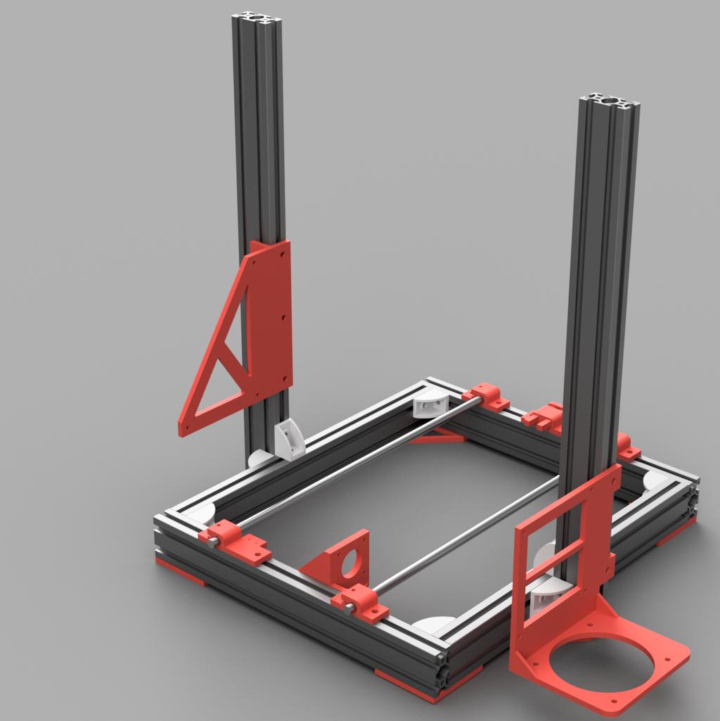
17 Attach Vertical Extrusions Parts Needed: 2x 440mm Extrusions with holes tapped 2x M5x10 Button Head Screw 2x M5x16 Socket Head Screw 2x Rubber Feet 1. Slide a 440mm extrusion onto each side of the bottom frame TAPPED END DOWN. Make sure to align all of the square nuts that must slide into the channels. 2. Slide the bottom Tee bracket to align with the bottom of the vertical extrusions. 3. Attach an M5x10 button head screw to the interior tapped hole through the tee bracket. 4. Attach an M5x16 socket head screw to the exterior tapped hole through the tee bracket, with a rubber foot between the screw head and the plastic tee bracket. 5. Tighten all screws attached directly to the vertical extrusions. 6. Before tightening the screws attached to the frame bottom, you need to position the vertical extrusions on the bottom frame. The back edge of the vertical 440mm extrusion should be 127mm from the back edge of the rear extrusion of the bottom frame. The most important part about positioning the vertical extrusion is ensure both extrusions are aligned, and equal distance from the back of the bottom frame. 7. Once the vertical extrusions are aligned, tighten the rest of the screws.

18 Mount Controller Board Mount and PSU Mount Parts Needed: 1x Anet Board Mount (Either With or Without Fan Mount) (Printed) 1x PSU Mount (Printed) 7x M5x10 Button Head Screw 7x M5 Square Nut OPTIONAL With Fan Mount 1x 80mm Fan 2x 80mm Fan Guard 8x M3x20 screws 8x M3 nuts 1. If using a fan, it is easier to mount the fan to the mount before mounting the board mount to the frame. 2. Attach fan to board mount and fan guards on the top and bottom of the fan using the M3x20 screws and nuts. 3. Attach the controller mount to the outside 20mm side of the vertical extrusions and lower to near the bottom of the extrusion, the lower the better. 4. Attach the PSU mount to the right vertical extrusion as shown.
19
20 Attach Z Motor Mounts and Motors Parts Needed: 8x 8x 2x 8x 8x 1x 1x M5x10 Socket Cap Screw M5 Nuts Stepper Motors M3x20 screws M3 washers Z Motor Mount Right (Printed) Z Motor Mount Left (Printed) 1. Slide the left motor mount onto the left vertical extrusion and the right motor mount on the right vertical extrusion. 2. Motor mount should be positioned so that the top of the mount is 25mm above the top of the bottom frame extrusion. 3. Tighten motor mount screws before installing motors. 4. Install motors on each mount using the M3 screws. Makes sure a washer is placed between the motor mount and each screw head, otherwise the screws will bottom out before securing the motor to the mount.
21 Attach 380mm Rods and Lead Screws Parts Needed: 2x 380mm Smooth Rods 1x Z Endstop mount (Printed) 1x Z Endstop (From A8) 2x Endstop Screws (From A8) 2x M5x10 Button Head Screws 2x M5 Square Nuts 2x Lead Screws 2x Flexible couplers 1x Assembled X carriage (From A8) 1. Slide Z Endstop mount down the front of the left vertical extrusion, and tighten the screws when the mount is close to the Z Motor mount. 2. Attach the Z endstop to the endstop mount using the original screws from the A8. 3. Attach flexible couplers to the Z motor shafts. 4. Attach Lead screws to each flexible coupler 5. Press the smooth rods into the rod holder holes in each of the Z motor mounts. 6. Place the assembled X carriage from the A8 onto the smooth rod and lead screws. Turn the lead screws by hand in order to lower the carriage to a more stable position at the bottom toward the motor mounts.

22

23 Assemble Z Rod Holders Parts Needed: 1x Z Rod Holder Left (Printed) 1x Z Rod Holder Right (Printed) 8x M5x10 Button Head Screw 8x M5 Square Nut 2x M3x20 screw 2x M3 Hex Nut Slide Z Rod holders onto extrusions Press rod into Z Rod Holder hole Place M3 hex nut into hex nut holder on each rod older Place M3x20 screw through hole into the hex nut Slide Z Rod holders until they are flush with the top of the extrusions and the smooth rod 6. Tighten M3 screw to clamp onto rods
24 Assemble Top Extrusion Cross Member Parts Needed: 2x Top Corner Plate (Printed) 2x Aluminum Corner Brackets 1x Wire Holder 17x M5x10 Button Head Screw 17x M5 Square Nut 1x M3x20 screw 1x M3 hex nut. 1x Wire clamp (From A8). 1. Assemble the components as shown. 2. Attach the wire clamp to the wire holder, but the wires will be run later. 3. Slide the Top Crossmember Assembly onto the vertical extrusions and tighten screws. Front: Back:


25


26 Attach LCD Parts Needed: 1x LCD Case Top (Printed) 1x LCD Base Left (Printed) 1x LCD Base Right (Printed) 1x LCD Screen (From A8) 4x M3 LCD Mounting Screws (From A8) 4x M3 Hex Nuts (From A8) 4x M5x10 Button Head Screws 4x M5 Square Nuts 1. Place the LCD Screen into the LCD Case Top. The screen portion should fit snugly in the square hole and sit flush with the flat front of the case. 2. Place M3 hex nuts into the slots in the left and right LCD Base. 3. Thread the original LCD screws through the holes in the LCD Case Top and into the holes in the bases that allow it to screw through the M3 hex nuts. 4. Once the LCD top is secured to the bases, attach it to the front extrusion in the printer base, center it, and tighten the screws. 5. Run the LCD Cable to the controller board. I ran mine under the frame.
27 Connect the Controller Board and PSU Parts Needed: 1x Anet Board V1 1x PSU Original mounting hardware from A8 1. Use all of the original screws and spacers that were used to mount both the controller board and the PSU. 2. For the PSU, the 3 screws will go through the plastic holes and into the back of the PSU. The PSU should be oriented with the terminal blocks down. 3. The Controller board should be mounted using the original screws and spacers. The spacers should go between the board and the plastic mount. Run the Wiring The wires need to be run form the various components to the Anet control board and PSU. Please refer to the original Anet A8 instructions on how to wire the printer to the board and PSU, if you need assistance. All wires should be reconnected to their original connection points. The path of the wires is your choice. Where possible, I ran wires inside open extrusion channels, and held them in place with printed wire channel clips. If you are running the wires in the channels, make sure that the wires have slack at the ends of the extrusions, ensuring that the sharp edges of the cut extrusions cannot damage the wire insulation and cause a short. I ran the X Carriage wires over the top cross member of the frame. I re-used one of the clear/white plastic wire mounts from the A8 and attached it to the wire holder block with an M3 screw and hex nut. Make sure the wires are well supported, but also have enough slack to allow free movement of the X and Y axis. Level the Z Axis To level the Z Axis, I recommend turning the Z Axis lead screws by hand until the Z Axis is all the way at the top and bumping against the rod holders. This will ensure your Z Axis is level. Now with the printer on, manually move the Z Axis down through the controller interface(do NOT HOME). The Z Endstop mount should be loose to allow you to manually adjust it s position. Move the Z Axis down until the print head is very close, but not touching the bed. Once the nozzle is within a millimeter or two of the bed, move the Z Endstop up until it clicks from touching the Z Axis, then tighten the Z Endstop mount in it s current position. Once the Z Endstop mount is tightened, move the Z Axis up and down with the controller and ensure you are happy with it s homing position (The nozzle is close to the bed without crashing into it). When you are happy, home all of the
28 axis, and level the bed with the leveling screws like you normally would on the Anet A8. Firmware My controller board was still using the stock Anet A8 firmware. After completing this frame rebuild, I found that my printer was capable of printing at much faster speeds, and the acceleration and jerk settings of the stock firmware caused significant corner bulging. I recommend downloading and installing the latest version of the Skynet firmware, which is a version of Marlin modified to support the Anet Board. This will allow you to modify the firmware settings to better fit your printer.
Part 7 Assembling the X axis
 Part 7 Assembling the X axis 1 2 The X axis is a key part of the printer, it carries the extruder on a carriage that moves the extruder laterally in the X axis. The x axis itself is moved vertically on
Code Product Qty 1 Top Vertex 3 2 Hot End Housing 1 3 Bottom Vertex 3 4 Print Platform Lock 3 5 End Stop Holder 3 6 Filament Feeder Motor Bracket 1 7
 List of Parts Code Product Qty 1 680mm Extrusion 3 2 Power Supply 1 3 240mm Extrusion 9 4 42mm Nema 17 Stepper Motor 3 5 Slider-Hotend Connecting Rod 6 6 48mm Nema 17 Stepper Motor 1 7 Linear Rail with
V4 Premium Kit. Prusa i3 Build Guide
 V4 Premium Kit Prusa i3 Build Guide Hi! Congratulations on your purchase of the DIYElectronics.co.za Prusa I3 kit, the best South African 3D Printer Kit! Hopefully this should serve as complete guide to
M2 Assembly. M2 Sub-Assemblies mm Belt Sub-Assembly mm Belt Sub-Assembly Spider Sub-Assembly... 4
 M2 Assembly Table of Contents M2 Sub-Assemblies... 3 630mm Belt Sub-Assembly... 3 702mm Belt Sub-Assembly... 3 Spider Sub-Assembly... 4 Idler Bolt Sub-Assembly... 8 Y Motor Sub-Assembly... 9 X Motor Sub-Assembly...
Assemble Instruction of Geeetech Acrylic. Prusa I3 Pro C
 Assemble Instruction of Geeetech Acrylic Prusa I3 Pro C Version 04-11-2016 Safety Instructions Building the printer will require a certain amount of physical dexterity, common sense and a thorough understanding
Assemble Instruction of Geeetech Acrylic Prusa I3. Pro & pro B
 Assemble Instruction of Geeetech Acrylic Prusa I3 Pro & pro B Version 04-11-2016 Safety Instructions Shenzhen GETECH CO.,LTD Building the printer will require a certain amount of physical dexterity, common
Kossel Rev B Build Guide V1.0
 Kossel Rev B Build Guide V1.0 1 Table of Contents: Step 1: BASE ASSEMBLY Gathering parts: Building the Corners and Base: Step 2: UPPER ASSEMBLY Building Upper: Step 3: VERTICAL RAIL INSTALLATION Building
Bed Extension Kit 16 Instructions
 The premier source of tooling, parts, and accessories for bench top machinists. Bed Extension Kit 16 Instructions This kit converts a 7 10, 7 12, and 7 14 mini lathe manufactured by SIEG (including those
Assemble Instruction of Geeetech Acrylic Prusa I3. pro C
 Assemble Instruction of Geeetech Acrylic Prusa I3 pro C Safety Instructions Shenzhen GETECH CO.,LTD Building the printer will require a certain amount of physical dexterity, common sense and a thorough
ABM International, Inc. Navigator Assembly Manual
 ABM International, Inc. 1 1.0: Parts List Tablet (Qty. 1) Tablet mount (Qty. 1) NOTE: Mount may appear and operate different then image below Control Box (Qty. 1) Motor Power Supply (Qty. 1) 2 X-axis motor
BIGBOT ASSEMBLY INSTRUCTIONS. 1/18/2017 V0.5
 BIGBOT ASSEMBLY INSTRUCTIONS www.bigbot-3d.com 1/18/2017 V0.5 FOREWORD: PLEASE TAKE CARE WHEN HANDLING THE GANTRY. THE ASSEMBLY SHOULD BE HANDLED ONLY BY THE ALUMINUM FRAME, AND AVOID TOUCHING OR LIFTING
Ender-3 3D Printer. Instructions for assembly
 Ender-3 3D Printer Instructions for assembly This guide is for the Ender-3 3D printer. Select the correct input voltage to match your local mains (220V or 110V). Because of software/hardware upgrades and
Printrbot Simple (Model 1403) Rev F Printrboard
 Rev F Printrboard") Printrbot Simple (Model 1403) Rev F Printrboard Printrbot Simple is currently shipping with the Rev F Printrboard. Check which rev Printrboard your Simple kit includes and use the corresponding instructions.
Printrbot Simple (Model 1403) Rev F Printrboard Printrbot Simple is currently shipping with the Rev F Printrboard. Check which rev Printrboard your Simple kit includes and use the corresponding instructions.
(Assembling Guide supplied by imakr ) with the support of MyMiniFactory.com
 with the support of MyMiniFactory.com") (Assembling Guide supplied by imakr ) with the support of MyMiniFactory.com Summary Congratulations on beginning on your journey into 3D printing with the STARTT 3D printer. In this guide, you will have
(Assembling Guide supplied by imakr ) with the support of MyMiniFactory.com Summary Congratulations on beginning on your journey into 3D printing with the STARTT 3D printer. In this guide, you will have
ABM International, Inc.
 ABM International, Inc. Lightning Stitch required 1 1.0: Parts List head and motor assembly (Qty. 1) Reel stand (Qty. 1) Needle bar frame clamp (Qty. 1) Motor drive (Qty. 1) 2 Cable harness with bracket
INVENT3D Printer Kit Disassembly Instructions
 INVENT3D Printer Kit Disassembly Instructions Version 6 AST2 10/26/16 1 I. General Disassembly Instructions Use the case layer drawings to ensure that components are stored in the appropriate location
Depending on the size you ordered you will have either 5 Foot sections which will build the 10 Foot frame or 6 Foot sections which will build the 12
 XL Quilting Frame 1 Depending on the size you ordered you will have either 5 Foot sections which will build the 10 Foot frame or 6 Foot sections which will build the 12 Foot frame Printed 2 June 2014 Updated
Delta Rostock mini G2& G2s Building instruction
 Delta Rostock mini G2& G2s Building instruction Safety Instructions ShenZhen GETECH CO.,LTD Building the printer will require a certain amount of physical dexterity, common sense and a thorough understanding
Nancy s Knit Knacks LLC 4 Yard Option Upgrade Kit Assembly Instructions and User Manual
 Nancy s Knit Knacks LLC 4 Yard Option Upgrade Kit Assembly Instructions and User Manual Thank you for purchasing our 4 Yard Option (4YO) Upgrade Kit. To install this upgrade you are simply going to assemble
The Phoenix. Professional Quilting Frame. Copyright January 1, 2016 Jim M. Bagley, GraceWood, Inc (Reproduction Prohibited) Version 2.
 Version 2.") The Phoenix Professional Quilting Frame Copyright January 1, 2016 Jim M. Bagley, GraceWood, Inc (Reproduction Prohibited) Version 2.1 1 The Phoenix Professional Quilting Frame Parts List Box 1...3 Box
The Phoenix Professional Quilting Frame Copyright January 1, 2016 Jim M. Bagley, GraceWood, Inc (Reproduction Prohibited) Version 2.1 1 The Phoenix Professional Quilting Frame Parts List Box 1...3 Box
Shapeoko XXL Assembly Guide
 Shapeoko XXL Assembly Guide 04/27/2016 XXL Packing LIst Item Qty Description Y-Carriage (left) 1 Y-Carriage (right) 1 X/Z Assembly 1 40 Rail 3 1 rail has mounting holes for controller Wasteboard Half 2
1.75mm Direct Titan Assembly
 1.75mm Direct Titan Assembly Learn how to assemble your Titan for use with 1.75mm filament in a direct configuration. Written By: Gabe S. 2018 e3d-online.dozuki.com/ Page 1 of 20 TOOLS: Hex Wrench, 1.5mm
0. Disassembly. Disassembly of the MK2 printer and upgrading to the MK2S using the upgrade kit. Written By: Jakub Dolezal
 0. Disassembly Disassembly of the MK2 printer and upgrading to the MK2S using the upgrade kit. Written By: Jakub Dolezal 2018 manual.prusa3d.com/ Page 1 of 12 Step 1 Preparing the printer Ensure the printer
Geeetech Delta Rostock mini G2 pro / G2s pro Building Instruction
 Geeetech Delta Rostock mini G2 pro / G2s pro Building Instruction (Document version: 04-11, 2016) CONTENT Safety Instructions... 1 Preparation... 2 1 Base Assembly... 3 1.1 Motor holder assembly... 3 1.2
HQ Precision-Glide Track Upgrade 2 Extension Kit for HQ Studio Frame Part# QF09750
 HQ Precision-Glide Track Upgrade 2 Extension Kit for HQ Studio Frame Part# QF09750 Important Note: Upgrading the track system on the HQ Studio Frame requires the use of this 2 Extension Kit (Part #QF09750),
LYMANBOT 3D PRINTER V3 Construction Manual
 LYMANBOT 3D PRINTER V3 Construction Manual Page 1 Read this whole Manual before starting to construct this Printer. User excepts all liability for the use of this Manual and the construction of this Printer.
The Portable Open Source 3D Printer
 http://web.archive.org/web/201502142011/http://www.tantillus.org/build_3.html Page 1 of 12 captures 12 Oct 12 - Feb 15 The Portable Open Source 3D Printer Home Start Case X/Y Axis Extruder Z Axis Electronics
Assembly Guide for Printrbot - Simple Maker s Edition 1405
 Assembly Guide for Printrbot - Simple Maker s Edition 1405 Last update: March 2016 Please Note: be careful on the steps that are underlined 1 Contents Tools Needed:... 3 First step: Check components and
HQ Pole Upgrade Kit for HQ Adjustable Table and HQ QuilTable Assembly Instructions 1
 HQ Pole Upgrade Kit for HQ Adjustable Table and HQ QuilTable Assembly Instructions QF09775 The pole upgrade kit can be used with or without the QF09700 HQ Precison-Glide track upgrade kit. What s Included
Removing and Replacing the Y-truck
 Service Documentation Removing and Replacing the Y-truck To remove and replace the Y-truck you will need the following tools: 4mm Allen wrench 12mm stamped flat wrench #2 Phillips screwdriver (magnetic
PRS Retro Z-Axis Installation
 PRS Retro Z-Axis Installation Page -1- PRS Retro Z-Axis Installation This document is a guide to installing the PRS Retro Z-axis on early ShopBot models. It describes installation for PR models with PK299
MatterHackers. How to Install an E3D v6 HotEnd on a Lulzbot. Upgrade your TAZ with a shiny new E3D hotend. Written By: Ryan Lutz
 MatterHackers How to Install an E3D v6 HotEnd on a Lulzbot TAZ 5 Upgrade your TAZ with a shiny new E3D hotend. Written By: Ryan Lutz 2017 matterhackers.dozuki.com Page 1 of 21 INTRODUCTION NOTE: This guide
Giraud Tool Company, Inc.
 Motor Upgrade for Gracey Trimmer This package is intended to allow the user to upgrade their Gracey trimmer with a higher rpm motor and convenience features not found in the production offering. This upgrade
Removing outter components
 Y Axis Motor Replacement Replacing the Y axis motor is a process that requires the individual to be somewhat mechanically inclined and can follow detailed instructions. If any of the following steps are
Hardware and Components:
 Hardware and Components: (A) 5/16 x 2 Hex Bolt (B) 5/16 x 2-1/4 Hex Bolt (C) 5/16 x 2-1/2 Hex Bolt (D) 4X 5/16 x 3/4 Hex Bolt (E) 4X 5/16 x 1-1/4 Hex Bolt (F) 11X 5/16 Flat Washer (G) 12X 5/16 Nylock Nut
Assembly Instructions Beta Prusa Standard & Deluxe
 Assembly Instructions Beta Prusa Standard & Deluxe 3D Printer Version 2.6 Date Page 1 / 67 General data about the assembly instructions for an incomplete machine according to appendix VI of the EG machinery
5. Extruder Assembly
 5. Extruder Assembly Guide for the assembly of the Extruder. Written By: Josef Prusa 2017 manual.prusa3d.com Page 1 of 22 Step 1 Get the necessary tools 2.5 and 1.5 mm Allen key Needle-nose pliers Step
OPERATIONAL MANUAL V1.0. Removing/Replacing Blades
 OPERATIONAL MANUAL V1.0 BLUEROCK WS-212 Wire Stripper Removing/Replacing Blades CAUTION!! IMPORTANT!! DANGER!! WARNING!! DISCONNECT MACHINE FROM POWER BEFORE PROCEEDING!! Estimated Completion Time: 90
Step 1 Assemble Base Frame Parts: 2040 Aluminium profile 250mm 1pcs Base Plate 1pcs M4-8mm screw 3pcs M4 T-Nut 3pcs
 Step 1 Assemble Base Frame 2040 Aluminium profile 250mm 1pcs Base Plate 1pcs M4-8mm screw 3pcs M4 T-Nut 3pcs Put the aluminium profile on the base plate, secure them with 3pcs M4-10mm screws & T-Nut Step
Removing the Z-Axis lead screw
 Page 1 of 8 TITLE: Sabre Z-Axis Lead Screw Replacement Procedure Gerber FastFact #: 5048 Supplied by: Gerber Hardware Support Last Modified: June 14, 2007 Summary: Tools used: The following procedure explains
This manual will aid in the assembly of the FireBall V90 and FireBall X90. The assembly of both machines will be identical, unless specified.
 This manual will aid in the assembly of the FireBall V90 and FireBall X90. The assembly of both machines will be identical, unless specified. Step #1 Lay all parts out to verify quantities. (2) 2 x 25-1/4
Installing CNC Stepper Motor Mounts On A Sherline Mill
 Installing CNC Stepper Motor Mounts On A Sherline Mill P/N 6700 (6710 Metric) 5000/5100/5400/5410 Mills P/N 6705 (6715 Metric) 2000/2010 Mills USING THE TEMPLATE BLOCKS TO LOCATE NEW MOUNTING HOLES FOR
Step 1 Assemble Base Frame
 Step 1 Assemble Base Frame Parts: 2040 Aluminium profile 250mm 1pcs Base Plate 1pcs M4-8mm screw 3pcs M4 T-Nut 3pcs Put the aluminium profile on the base plate, secure them with 3pcs M4-10mm screws & T-Nut
Installing CNC Stepper Motor Mounts On A Sherline Lathe
 Installing CNC Stepper Motor Mounts On A Sherline Lathe P/N 6720 (6725 Metric) 4000/4100/4500/4600 Lathes P/N 6730 (6735 Metric) 4400/4410 Lathe USING THE TEMPLATE BLOCKS TO LOCATE NEW MOUNTING HOLES FOR
Lead Screw Upgrade. How to upgrade your ROBO R1 to the new Lead Screw Upgrade Pack. Written By: Harrison Team RoBo 3D
 Lead Screw Upgrade How to upgrade your ROBO R1 to the new Lead Screw Upgrade Pack. Written By: Harrison Team RoBo 3D 2017 guide.robo3d.com Page 1 of 14 Step 1 Lead Screw Upgrade Begin by powering off and
Assembly Instructions. Beta Prusa DualX 3D Printer
 Assembly Instructions Beta Prusa DualX 3D Printer Version 2.6 Date Page 1 / 72 General data about the assembly instructions for an incomplete machine according to appendix VI of the EG machinery directive
Hardware and Components:
 Hardware and Components: (A) 4X 5/16 x 1 Carriage Bolt (B) 2X 5/16 x 2-1/4 Carriage Bolt (C) 2X 5/16 x 3-1/4 Hex Bolt (D) 2X 5/16 x 3/4 Hex Bolt (E) 2X 5/16 x 1-1/4 Hex Bolt (F) 5/16 x 2-1/4 Hex Bolt (G)
re3d Assembling Gigabot: "Flatpack"
 re3d Assembling Gigabot: "Flatpack" Your Gigabot was assembled, calibrated, tested, and taken apart for shipping purposes. All you need to do is reassemble it, and you're ready to go! Written By: Chris
Shenzhen GETECH CO.,LTD GEEETECH. Building Instructions of Geeetech Prusa I3 X
 Building Instructions of Geeetech Prusa I3 X CONTENT CONTENT... 2 Safety Instructions...3 Preparation...4 Unfold the box and check the package list... 5 1. Assemble the threaded rods of Y axis... 6 2.
Assembly Instructions Beta Prusa Standard & Deluxe
 13/11/12 Assembly Instructions Beta Prusa Standard & Deluxe 3D Printer Version 1.0 Date 13/11/12 Page 1 / 66 General data about the assembly instructions for an incomplete machine according to appendix
Heacent 3D printer assembly manual. Prusa i3
 Heacent 3D printer assembly manual Prusa i3 Y-axis assembly 1. Y axis motor section: Find the belowing parts bag, Y-axis motor Assembled parts are separated as shown below, note that the motor between
Introduction. Rocky Mountain Westy Swing Away Carrier Kit Installation Instructions
 Rocky Mountain Westy Swing Away Carrier Kit Installation Instructions Introduction Thank you for purchasing the Rocky Mountain Westy Swing Away Carrier Kit. We pride ourselves in the products we develop
Titan Aero Assembly. Titan Aero Assembly. Learn to assemble your Titan Aero. Written By: Gabe S e3d-online.dozuki.
 Titan Aero Assembly Learn to assemble your Titan Aero Written By: Gabe S. 2018 e3d-online.dozuki.com/ Page 1 of 26 INTRODUCTION The Titan Aero is a very similar build to a Titan and a V6 put together (which
Juki Quilting Frame. Assembly and Use Instruction Manual. Max Overall Dimensions: Length Crib: King: Tall: Wide: 42
 Juki Quilting Frame Assembly and Use Instruction Manual Max Overall Dimensions: Length Crib: 63 1 4 King: 128 1 4 Tall: 45 3 4-51 3 4 Wide: 42 Copyright January, 2015 Version 9.6 (Page 1) Contents Parts
model tsa-sa48 Sliding Crosscut Table installation guide
 model tsa-sa48 Sliding Crosscut Table installation guide A Note About Color Variations Among Anodized Aluminum Components Congratulations on the purchase of this SawStop Sliding Crosscut Table. We at SawStop
Bend-Tech Dragon Assembly Manual
 p.1 Bend-Tech Dragon Assembly Manual IMPORTANT: Please read before unpacking. Place shipping container in a wide open area where you will have room to work and assemble this product. Shipping The Dragon
EmagiKit. Privacy Pod Plus. Quiet. Easy. Affordable. INSTRUCTIONS ASSEMBLY
 EmagiKit Privacy Pod Plus Quiet. Easy. Affordable. INSTRUCTIONS ASSEMBLY DIMENSIONS AND COMPONENTS 47 47 Ceiling Unit 2-B 2-L 2-R Glass Door Corner Trim Door Handle 90 Adjustable Height Work Surface 1-B
Taper Attachment for G4016 Gear Head Lathe
 Taper Attachment for Gear Head Lathe MODEL H0775 INSTRUCTION SHEET COPYRIGHT AUGUST, 2004 BY GRIZZLY INDUSTRIAL, INC. WARNING: NO PORTION OF THIS MANUAL MAY BE REPRODUCED IN ANY SHAPE OR FORM WITHOUT THE
Elimination of Elevator Bounce
 For the Agilent Archon Autosampler Rework Instructions CAUTION This kit is intended for use by Agilent Service personnel only. Elevator Removal 1 Open top cover. 2 Open front lower door. 3 Remove vial
MobileTrak5 Installation Instructions
 MobileTrak5 Installation Instructions PLEASE OPEN ALL BOXES & CHECK TO MAKE SURE YOU HAVE ALL PIECES REQUIRED READ ALL INSTRUCTIONS BEFORE STARTING Tools Required for Assembly 7/16, 1/2 Wrench Phillips
ASSEMBLY INSTRUCTIONS FOR THE MILLRIGHT CNC CARVE KING
 ASSEMBLY INSTRUCTIONS FOR THE MILLRIGHT CNC CARVE KING Version 1.05 Important safety rules for operating your MillRight CNC Carve King: Never place your hands near a spinning end mill or bit. Unplug the
Side Winder R o u t e r L i f t.
 Woodpeckers PRECISION WOODWORKING TOOLS Side Winder R o u t e r L i f t. INSTALLATION INSTRUCTIONS The wrench handle must be pointing left in order to fully insert or remove it. Lift Wrench Once fully
Written By: Brook Drumm
 Simple 1401 Assembly For kits produced between 1/15/14-6/1/14. This guide is for kits with the Fan Shroud. Instructions for metal and wood extruder (and bed) included below. Written By: Brook Drumm TOOLS:
Sliding Crosscut Table installation guide
 Sliding Crosscut Table installation guide model tsa-sa48 A Note About Color Variations Among Anodized Aluminum Components Congratulations on the purchase of this SawStop Sliding Crosscut Table. We at SawStop
CRP700 Benchtop Basic CNC Machine Assembly Instructions. Updated 9/11/2014 SHEET 1 of 25
 CRP700 Benchtop Basic CNC Machine Assembly Instructions Updated 9//0 SHEET of NOTE: This piece of extrusion is mounted wide side up Quick Tip: Lay extrusion on table as shown for easy assembly BASE ASSEMBLY:.
Contractors Rack Assembly and Installation Instructions
 Part # 18601 & 16601 Contractors Rack Assembly and Installation Instructions 4751 Littlejohn St. Unit A, Baldwin Park, CA 91706 Page 1 of 12 11/13/08 Thank you for purchasing the Paramount Restyling Contractors
CRP700 Benchtop Basic CNC Machine Assembly Instructions. Updated 10/24/2014 SHEET 1 of 24
 CRP700 Benchtop Basic CNC Machine Assembly Instructions Updated 0//0 SHEET of NOTE: This piece of extrusion is mounted wide side up Quick Tip: Lay extrusion on table as shown for easy assembly BASE ASSEMBLY:.
Fan, Eden/Northfield, GS Installation Instructions (SKU ) Packing List
 Packing List") Packing List Blower Assembly Wiring Harness Rheostat with Nut and Knob Snap Disc Mounting Hardware (4) rubber grommets with brass inserts, (4) nuts, (4) washers. Cover Assembly Installation Warning: Make
Packing List Blower Assembly Wiring Harness Rheostat with Nut and Knob Snap Disc Mounting Hardware (4) rubber grommets with brass inserts, (4) nuts, (4) washers. Cover Assembly Installation Warning: Make
N. 15th Street, Middlesboro, KY FLIP TARP DUMP BODY INSTALLATION INSTRUCTIONS
 1-800-248-7717 1002 N. 15th Street, Middlesboro, KY 40965 FLIP TARP DUMP BODY INSTALLATION INSTRUCTIONS Congratulations on your purchase of a Mountain Flip Tarp Dump Body tarping system. With tarping systems
Intercooler Shroud and Belt Cover for WRX
 Intercooler Shroud and Belt Cover for 2015+ WRX 2016-05-18 Thank you for purchasing this PERRIN product for your car! Installation of this product should only be performed by persons experienced with installation
Wanhao D9. Assembly and installation manual. This work is licensed under a Creative Commons Attribution 4.0 International License.
 Wanhao D9 Assembly and installation manual This work is licensed under a Creative Commons Attribution 4.0 International License. Table of Contents Introduction 2 Compatibility 2 What s in the box? 2 Raise3D
Fortress Fe Posts must always be secured to the deck framing. Fortress Fe Posts should never be attached to only the deck boards.
 Installation Instructions for Fortress Horizontal Cable Panel System with UB-05 Brackets and Fe Posts It is the responsibility of the installer to meet all code and safety requirements, and to obtain all
BBF Series Blower Base Frame Assembly Instructions Rev.: BFA-9105
 BBF Series Blower Base Frame Assembly Instructions Rev.: BFA-9105 These assembly instructions are to be used as a general reference guide to facilitate assembly. Please consult the blower, bushing, sheave,
C70 Window Roller Repair Taken from: Heres the problem:
 C70 Window Roller Repair Taken from: http://www.volvospeed.com/vs_forum/topic/115086-how-to-c70-window-rollers-permanent-fix/ Heres the problem: This happened to two separate window assemblys on my c70
JK FRONT FENDER FLARE INSTALLATION INSTRUCTIONS
 JK FRONT FENDER FLARE INSTALLATION INSTRUCTIONS TOOLS NEEDED 3/16 Allen Wrench 1/2 Socket or wrench 10mm Socket Flat head screwdriver HARDWARE 5/16 x 3/4 button heads (14) 5/16 x 1 button heads (8) 5/16
TRAILMATE METEOR ASSEMBLY MANUAL
 TRAILMATE METEOR ASSEMBLY MANUAL The Trailmate Meteor recumbent has been designed for easy assembly. This means more time to enjoy the smooth ride with single speed, 3 speed coaster brake and 21 speed
TL4100 Top 5 Build Tips
 TL4100 Top 5 Build Tips 1: Top Plate When assembling the top plate, align the top of the top plate brackets with the top of the rods. This can be done by placing a hard flat object (such as a ruler) on
Tin Lizzie 18 Assembly Instructions
 Tin Lizzie 18 Assembly Instructions Revision: 07/29/16 Table of Contents Aides 3 Before You Begin 5 Aides 5 Tools 6 Perfect Stitch Parts 2 12 Modify the Machine 12 Prepare Drill Templates 12 Front Display
Anti-Chattering Retrofit Assembly
 Anti-Chattering Retrofit Assembly Please follow through these instructions carefully and thoroughly. If you have questions, feel free to contact a Bend-Tech service representative at our office 651-257-8715
Metroboard Pulley Replacement Procedure
 Metroboard Pulley Replacement Procedure 1) Remove the two transmission cover screws (1/8 allen driver). Then remove the transmission cover. Note there is a split lock washer and flat washer as well, so
BABY WOLF LOOM. Assembly Instructions for Knocked-Down Looms
 BABY WOLF LOOM Assembly Instructions for Knocked-Down Looms BEFORE YOU BEGIN Please read through the directions before beginning to assemble your loom. Unpack the loom parts carefully. Do not throw away
3D PRINTER. Pack 11. Anything you can imagine, you can make! 3D technology is now available for you at home! BUILD YOUR OWN
 BUILD YOUR OWN Pack 11 Anything you can imagine, you can make! 3D PRINTER Compatible with Windows 7 & 8 Mac OS X 3D technology is now available for you at home! BUILD YOUR OWN 3D PRINTER CONTENTS PACK
Fortress Fe Posts must always be secured to the deck framing. Fortress Fe Posts should never be attached to only the deck boards.
 Installation Instructions for FortressCable H-Series Cable Panel System With UB-05 Brackets and Fe Posts It is the responsibility of the installer to meet all code and safety requirements, and to obtain
Replacing the Reciprocator on an SWF Multi-head.
 Replacing the Reciprocator on an SWF Multi-head. Follow the instructions below to replace the reciprocator in the SWF multi-head machines. The tools required are found in the tool kit that came with the
3/8-16 x 3/4 cap screw. 3/8-16 hex nut for above screws. 1/4-20 x 3/4 socket cap screw. 3/16 short arm hex key (not to scale)
") Super Slab Roller 24, 30 and 36 models Worktable Assembly Directions P.O. Box 89 Cheney, WA 99004 USA 509.235.9200/800.23.7896 Fax: 509.235.9203 www.northstarequipment.com Revised September, 2006. All
Super Slab Roller 24, 30 and 36 models Worktable Assembly Directions P.O. Box 89 Cheney, WA 99004 USA 509.235.9200/800.23.7896 Fax: 509.235.9203 www.northstarequipment.com Revised September, 2006. All
Jass.Performance Low Profiles Installation Manual
 Jass.Performance Low Profiles Installation Manual What is in the box: 2x Adapter Frame 2x Outer Panels 2x Inner Panels Pushrod, Ball Joints & Brackets 2x Hella Headlights 6x Springs 4x M6x25 Cross Head
Q-Zone Hoop-Frame. Assembly Instructions. Copyright July 11, 2018 Grace Company (Reproduction Prohibited) Version 1.8
 Version 1.8") Q-Zone Hoop-Frame Assembly Instructions Copyright July 11, 2018 Grace Company (Reproduction Prohibited) Version 1.8 Table of Contents Table of Contents... i Warranty... ii Parts List Box 1...iii Box 2...
Q-Zone Hoop-Frame Assembly Instructions Copyright July 11, 2018 Grace Company (Reproduction Prohibited) Version 1.8 Table of Contents Table of Contents... i Warranty... ii Parts List Box 1...iii Box 2...
Assembly Instructions
 Assembly Instructions Note: Prior to assembly, be sure to remove all printing pads from the printed parts and also be sure to sort through and organize all of your hardware before assembly this will help
Hatchback Wing Riser Kit
 Hatchback Wing Riser Kit 2015-06-11 Thank you for purchasing this PERRIN product for your car! Installation of this product should only be performed by persons experienced with installation of aftermarket
FLIP TARP SINGLE & DOUBLE UNDERBODY TRAILERS
 1-800-248-7717 1002 N. 15th Street, Middlesboro, KY 40965 FLIP TARP SINGLE & DOUBLE UNDERBODY TRAILERS INSTALLATION INSTRUCTIONS Congratulations on your purchase of a Mountain Flip Tarp Trailer system.
FBX1104P FBX1104 FBX1106P FBX1106
 FBX1104P FBX1104 FBX1106P FBX1106 Second edition : September 2004 No. 040037 INTRODUCTION Thank you for your purchasing Kansai Special's FBX Series. Read and study this instruction manual carefully before
Replacing a Wheel on the Pinch Wheel assembly
 14140 NE 200th St - Woodinville, WA. 98072 - PH: (425) 398-8282 - Fax: (425) 398-8383 Replacing a Wheel on the Pinch Wheel assembly Determine which pinch wheel assembly your plotter or cutter has. See
Installation Instructions for FC2 & FC15 Forward Controls for the Super Magna
 Installation Instructions for FC2 & FC15 Forward Controls for the Super Magna It is highly recommended that you use a thread lock compound such as Loctite brand on all threads to keep them from vibrating
CNC Router Parts. Standard Rack & Pinion Drive Assembly Instructions
 CNC Router Parts Standard Rack & Pinion Drive Tools List The following tools will be used for assembly and installation of the Standard Rack & Pinion Drive: Imperial Allen Wrench Set - 3/32", 5/32", 3/16",
Bluetooth DRO Installation for Bench Mills
 The premier source of tooling, parts, and accessories for bench top machinists. Bluetooth DRO Installation for Bench Mills These instructions describe how to install the following products: 5494: Digital
UNIVERSAL RETROFIT KIT
 UNIVERSAL RETROFIT KIT Midwest Office 444 Lake Cook Road, Suite 22 Deerfield, IL 60015 Phone (847) 940-9305 Fax (847) 940-9315 www.flashcutcnc.com 1998-2012 FlashCut CNC, Inc. Table of Contents THANK YOU...
Legacy Woodworking Machinery a division of Phantom Engineering. The Legacy CNC. Assembly Manual
 Legacy Woodworking Machinery a division of Phantom Engineering The Legacy CNC Assembly Manual New Orientation of the Legacy Step one: Re-orientation of the machine Remove the X-axis screw and supports.
INSTALLATION MANUAL PBL-UMP
 INSTALLATION MANUAL PBL-UMP Table of Contents Warning Statements... 4 Parts List... 5 Installation Tools... 5 Features... 7 Projector Preparation... 8 Bracket Installation... 10 Leveling the Mounting Bracket...
Fortress Fe Posts must always be secured to the deck framing. Fortress Fe Posts should never be attached to only the deck boards.
 Installation Instructions for FortressCable H-Series Stair Panels with Simplified Stair Bracket SSB-05 and Fe Posts It is the responsibility of the installer to meet all code and safety requirements, and
Page 1. SureMotion Quick-Start Guide: LACPACC_QS 1st Edition - Revision A 03/15/16
 R K C T I Repair Kit Product Compatibility Repair Kit # Linear Actuator Assembly # LACPACC-002 LACPACC-003 LACP-16TxxLP5 (0.5-in lead screw pitch) LACP-16TxxL1 (1-in lead screw pitch) C P I R K 4 ea Flanged