This manual will aid in the assembly of the FireBall V90 and FireBall X90. The assembly of both machines will be identical, unless specified.
|
|
|
- Lorin Bates
- 6 years ago
- Views:
Transcription
 2 x 25-1/4 PVC (2) 1-1/4 x 25-1/4 PVC (2) Base Ends (2) Gantry Uprights (1) Gantry Back (1) Gantry Bottom (1) Complete Z Axis with Drive Nut Installed and Tool Holder Mounting Bolts Installed (2)")
1 This manual will aid in the assembly of the FireBall V90 and FireBall X90. The assembly of both machines will be identical, unless specified. Step #1 Lay all parts out to verify quantities. (2) 2 x 25-1/4 PVC (2) 1-1/4 x 25-1/4 PVC (2) Base Ends (2) Gantry Uprights (1) Gantry Back (1) Gantry Bottom (1) Complete Z Axis with Drive Nut Installed and Tool Holder Mounting Bolts Installed (2) Gantry Slide Blocks (8) Rail End Bushings with Bolts Installed (4) Bearing Holders with Bearings Installed (1) Drive Nut Block with Drive Nut Installed and Hardware (2) 3/4 x 24 Linear Shafts (2) 3/4 x 16 Linear Shafts (X90 will have (2) 23 Linear Shafts in place of 16 Shafts) (12) Motor Mount Screws with Stand offs and Washers (4) Shaft Collar Clamps with Delrin Washers (6) 1/4-20x1-3/4 Machine Screws (30) #12 Flat Washers (24) 1/4-20 Hex Nuts (6) 1/4-20 Acorn Head Nuts (4) 1/4-20x19-1/4 Threaded Rod (X90 will have (4) 1/4-20x25-7/8 Thread Rod in place of 19-1/4 ) (4) 1/4-20x27-1/4 Threaded Rod (1) Lead Screw 26 Long with Coupler Installed (1) Lead Screw 18 Long with Coupler Installed (X90 will have (1) 24-3/4 in place of 18 ) (1) Spoil Board and Mounting Hardware (MDF or Aluminum, see order for detail (3) Allen Wrenches


2 Step #2 Lay the Based Ends out with the Table Support Bar facing up. Then take (4) of the Rail End bushings and install them into the holes as shown.

 #12 Washers,")


3 Step #3 Flip the Base Ends over and fasten the Rail End Bushings as shown. This will require (4) #12 Washers, (2) 1/4-20 Hex Nuts, and (2) 1/4-20 Acorn Nuts. On one of the Base Ends use both Acorn Nuts and the other will use both Hex Nuts. Leave Nuts loose for later adjustments.


4 Step #4 Take the (4) 1/4-20 x 27-1/4 Threaded Rods and place a #12 washer at the end of each one. Then take a 1/4-20 Acorn Nut and thread it onto the end end the washer was placed. Step #5 Take the Base End with the Acorn Nuts attached and feed the Threaded Rod through the the holes as shown.


5 Step #6 Take the Base End with the Thread Rod and lay it flat with the Thread Rod facing up. Take the (4) PVC tubes and place them onto the Base End as shown. The PVC will sit in the pockets on the Base End.


6 Step #7 Take the (2) 3/4 x 24 Linear Shafts and place them into the Rail End Bushings in the Base End with the PVC and Threaded Rod. Then take the (2) Gantry Slide Blocks and slide them over the rails with the blue bearings facing towards the table support bar. You will use one Gantry Slide per Linear Shaft.


7 Step #8 Take the remaining Based End and install it over the Threaded Rod, PVC, and Linear Shafts. Step #9 Take (4) #12 Washers and (4) 1/4-20 Hex Nuts and fasten the Base End to the Threaded Rod that is exposed. Leave the nuts loose for future adjustment. At this point square the Base and tighten the Threaded Rod. Make any adjustments necessary to square the Base. Do not over tighten the Threaded Rod. Once this is finished the Base of the Machine is complete.


 #12 Washers and (4) 1/4-20 Hex Nuts and")
8 Step #10 Take the (2) Gantry Uprights and lay them out with the pockets facing up. Take the remaining (4) Rail End Bushings and install them as shown. Step #11 Take the Gantry Uprights and flip them over. Then take (4) #12 Washers and (4) 1/4-20 Hex Nuts and fasten the Rail End Bushings to the Gantry Uprights. Leave them loose for future adjustments.
 Step #13 Take the Z Axis and slide it onto the Gantry Upright with the Linear Rails.")
9 Step #12 Flip the Gantry Uprights over so the Rail End Bushings are facing upwards. Then take the 3/4 x 16 Linear Shafts and install them into the Rail End Bushings of one of the Gantry Uprights. (If you are assembling the X90 you will use the 23 long Linear Shafts and not the 16 ) Step #13 Take the Z Axis and slide it onto the Gantry Upright with the Linear Rails. The front of the Z Axis will need to face towards the front of the Gantry Upright as shown.


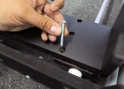
10 Step #14 Take the remaining Gantry Upright and install it onto the rails. Then lay the Gantry assembly face down as shown. Step #15 Take the Gantry Bottom and place it flat with the grooves facing down. Take the drive nut block and remove the hardware (Bolts, Nuts, and Washers). Take the (2) bolts and insert them as shown.

11 Step #16 Flip the Gantry Bottom over so the bolts and grooves are facing up.
 of them on each bolt.")

 #12")


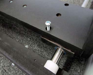
12 Step #17 Take (4) #12 Washers and place (2) of them on each bolt. Then install the Gantry Drive Nut block with the Drive Nut facing the thin side of the Gantry Bottom. Then take the remaining (2) #12 Washers and (2) Hex Nuts place them as shown. Leave these loose for future adjustments. Step #18 Take the Gantry Bottom and place it into the Gantry Assembly as shown.
 #12 Washers and (4) 1/4-20 Hex Nuts and thread them onto each end of the Threaded Rod and shown.")

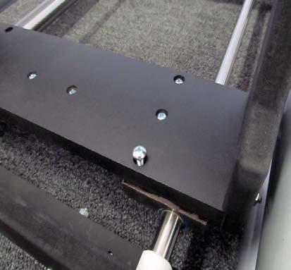
13 Step #19 Take (2) 1/4-20 x 19-1/4 Threaded Rods and insert them into the proper holes. Then take (4) #12 Washers and (4) 1/4-20 Hex Nuts and thread them onto each end of the Threaded Rod and shown. (X90 will use 25-7/8 Threaded Rod in place of 19-1/4 ) Step #20 Take the Gantry Back and repeat Step #19 as shown. Once this is finished, then tighten the Threaded Rod and Square the Gantry. Make an adjustments necessary to square the Gantry. Once the Gantry is Square, then rotate the Linear Shafts until the Z axis slides side to side freely. Then tighten the Rail End Bushings. Do not over tighten the Thread rod or the Rail End Bushings.


14 Step #21 Take the Gantry Assembly and roll it onto the the Base Assembly as shown. Step #22 Take (6) 1/4-20 x 1-3/4 Machine Screws and insert them as shown.
15

16 Step #23 Take (6) #12 Washers and (6) 1/4-20 Hex Nuts and install them as shown.


17 Your machine should now be to the following point. At this point slide the Gantry forward and backwards while rotating the Linear Shafts until the gantry slides freely. Tighten the Base Assembly Rail End bushings to lock this position. Also tighten the (6) bolts for the Gantry Bottom. Do not over tighten the Rail End bushings. Step #24
,")
 Shaft")


18 Take (1) 16 Lead Screw (24-3/4 if Assembling X90), (4) Bearing Holders, (4) Delrin Washers, and (4) Shaft Collars Clamps and assembly the Lead Screw section as shown. Tighten the set screw on the collar clamps after assembled. Make sure there is no play in the Lead Screw and the screw turns freely.


 #8")


19 Step #25 Take the remaining Lead Screw and repeat Step #24 for assembly of the Base Lead screw section. Once this is done and the clamps are tight. Make sure the screw turns freely, then tighten the Gantry Drive Block down from Step #17. Once this is done recheck to make sure the screw turns freely. Adjust if necessary. Step #26 Install Motors using the supplied Motor Mounting Hardware (12) x 2 Socket Cap Screws (12) #8 Washers (12) Nylon Stand offs.. Remember to grind/file a flat on the motor shaft and align the flat with the set screw on the aluminum coupler. Once the motors are tightened to the Machine then you will tighten the set screw in the coupler to the motor shaft. The image below shows where the Motor Mounting Hardware attaches.
1/4-20 x 4 Machine Screws.")

20 Step #27 Install the Spoil Board. You will use the (4)1/4-20 x 4 Machine Screws. If you have the Aluminum Spoil Board please refer to the Aluminum Spoil Board Assembly Instructions on our Website. You have now fully assembled your machine. Time to make some chip and ENJOY!!
GlideRite Retractable Cover System For HotSpring & Tiger River Spas (except Classic & pre-2000 Landmark Spas)
") List of Contents Quantity Description 12 #10 x 1 ½ Flat Head Phillips Screw (see pg. 2) 2 #10 x ½ Pan Head Phillips Screw (see pg. 2) 8 ¼ x 2 ½ Lag Bolt (see pg. 2) 7 ¼ 20 x 5 / 8 Hex Head Bolt (see pg.
List of Contents Quantity Description 12 #10 x 1 ½ Flat Head Phillips Screw (see pg. 2) 2 #10 x ½ Pan Head Phillips Screw (see pg. 2) 8 ¼ x 2 ½ Lag Bolt (see pg. 2) 7 ¼ 20 x 5 / 8 Hex Head Bolt (see pg.
GlideRite Retractable Cover System For Hot Spot Spas (SE & SLX only)
") List of Contents Quantity Description 12 #10 x 1 ½ Flat Head Phillips Screw (see pg. 2) 2 #10 x ½ Pan Head Phillips Screw (see pg. 2) 8 ¼ x 2 ½ Lag Bolt (see pg. 2) 7 ¼ 20 x 5 / 8 Hex Head Bolt (see pg.
List of Contents Quantity Description 12 #10 x 1 ½ Flat Head Phillips Screw (see pg. 2) 2 #10 x ½ Pan Head Phillips Screw (see pg. 2) 8 ¼ x 2 ½ Lag Bolt (see pg. 2) 7 ¼ 20 x 5 / 8 Hex Head Bolt (see pg.
CNC Router Parts PRO Machine Kit Cable Track Installation Instructions
 1 1 X CABLE TRACK TRAYS & BRACKETS The cable track on the side of the system is supported by a metal tray (or multiple trays for longer systems such as a PRO4896). These trays hang from brackets on the
SatNOGS. SatNOGS Rotator v3 Mechanical Assembly. This is the assembly guide for the third version of the SatNOGS Rotator.
 SatNOGS SatNOGS Rotator v3 Mechanical Assembly This is the assembly guide for the third version of the SatNOGS Rotator. Written By: Pierros Papadeas 2017 satnogs.dozuki.com Page 1 of 19 INTRODUCTION Notes:
CRP700 Benchtop Basic CNC Machine Assembly Instructions. Updated 10/24/2014 SHEET 1 of 24
 CRP700 Benchtop Basic CNC Machine Assembly Instructions Updated 0//0 SHEET of NOTE: This piece of extrusion is mounted wide side up Quick Tip: Lay extrusion on table as shown for easy assembly BASE ASSEMBLY:.
MAG-CONV Basic, 48, 48R & Midline Front Mount
 Parts Required: Tools Used: Mag Wheels Brakes Brake Rods Mounting Bracket Anti Tippers 7/16" Wrench Screw Driver Rubber Mallet 5/8 Wrench 5mm Allen Wrench Step Execution Figures 1 Remove front 5" total
Zen Toolworks CNC Carving Machine DIY Kit User Installation Manual
 User Installation Manual Visit Us At: http://www.zentoolworks.com or http://www.zentoolworks.com/zenwiki/mediawiki Contact Us At: zentoolworks@gmail.com 1 P-01, Nema 17 Stepper Motor, 3 P-02, Motor Shaft
AX1001. Smith/Functional training Combo-free weight ASSEMBLY INSTRUCTIONS
 AX1001 Smith/Functional training Combo-free weight ASSEMBLY INSTRUCTIONS EXPLODED DIAGRAM 83 84 84 85/86 87 87 88 89 90 91 62 64 64 64 64 64 64 65 65 65 65 66 66 65 66 66 65 63 63 66 67 68 55 66 66 70
CRP700 Benchtop Basic CNC Machine Assembly Instructions. Updated 9/11/2014 SHEET 1 of 25
 CRP700 Benchtop Basic CNC Machine Assembly Instructions Updated 9//0 SHEET of NOTE: This piece of extrusion is mounted wide side up Quick Tip: Lay extrusion on table as shown for easy assembly BASE ASSEMBLY:.
Deck Mount Installation with Bench
 Deck Mount Installation with Bench 1. Mark track with square. 2. Cut tracks with saw. 3. Drill ¼ hole (if needed.) 4. Countersink track. 5. Countersink all track 6. File all track ends. ends. 7. Lay out
User Instructions Multiline Otter Scoreboard Caddy Assembly
 List of parts: User Instructions Multiline Otter Scoreboard Caddy Assembly Single Caddy Double Caddy 1 1 Base assembly with attached wheels 2 4 1 1 2 4 4 8 10 20 12 Uprights (60 or 74 aluminum extrusion)
Page 1. SureMotion Quick-Start Guide: LACPACC_QS 1st Edition - Revision A 03/15/16
 R K C T I Repair Kit Product Compatibility Repair Kit # Linear Actuator Assembly # LACPACC-002 LACPACC-003 LACP-16TxxLP5 (0.5-in lead screw pitch) LACP-16TxxL1 (1-in lead screw pitch) C P I R K 4 ea Flanged
TIRE RACK INSTALLATION INSTRUCTIONS Dodge Sprinter
 Aluminess Products Inc 9402 Wheatlands Ct. #A Santee, CA 92071 619-449-9930 TIRE RACK INSTALLATION INSTRUCTIONS 07-11 Dodge Sprinter Please read before beginning Stainless steel hardware may bind together
IDR assembly instructions:
 IDR assembly instructions: Required Tools: 2 X 12mm Open End Wrench 14mm open end wrench #2 Phillips Head Screw Driver (Drill with adjustable torque clutch recommended) 8mm nut driver (Supplied in IDR-AK)
Leafy Greens Spinner Construction Manual
 Leafy Greens Spinner Construction Manual University of Houston Conrad N. Hilton College Food Science Lab Materials list: Base and Armature Approximately 8-1 PVC cut into sections o 3-22.5 o 2-7 o 2-4 o
Chain Drive Vise. Installation Instructions. (revised 05/04/2016)
") Chain Drive Vise Installation Instructions (revised 05/04/2016) Lie-Nielsen Chain Drive Vise Instructions Table of Contents page About Your Chain Drive Vise 3 Parts List 4 Exploded Parts Diagram 5 step
Chain Drive Vise Installation Instructions (revised 05/04/2016) Lie-Nielsen Chain Drive Vise Instructions Table of Contents page About Your Chain Drive Vise 3 Parts List 4 Exploded Parts Diagram 5 step
Code Product Qty 1 Top Vertex 3 2 Hot End Housing 1 3 Bottom Vertex 3 4 Print Platform Lock 3 5 End Stop Holder 3 6 Filament Feeder Motor Bracket 1 7
 List of Parts Code Product Qty 1 680mm Extrusion 3 2 Power Supply 1 3 240mm Extrusion 9 4 42mm Nema 17 Stepper Motor 3 5 Slider-Hotend Connecting Rod 6 6 48mm Nema 17 Stepper Motor 1 7 Linear Rail with
SOCCER TABLE. Assembly Instructions
 Updated: 5/4/16 SOCCER TABLE Assembly Instructions Table of Contents Parts Identifier... 3 Hardware Identifier. 4 Table Assembly Instructions... 5 Table Assembly Pictures..... 6, 7, 8 2 Page Parts Identifier
INSTALLATION INSTRUCTIONS FOR FRONT CASTING DECK RAIL Ranger
 INSTALLATION INSTRUCTIONS FOR FRONT CASTING DECK RAIL Ranger TOOLS REQUIRED FOR INSTALLATION: Drill motor, (1) 5/16 inch drill bit, (1) 13/64 drill bit, (1) 3/16 inch hex wrench (1) 3/32 inch hex wrench.
For additional assistance call
 The following pages will help guide you through the process of assembling your new 48 custom prize wheel. Choose an assembly area with plenty of room to lay your pieces on the floor and also a bench or
Removing the Z-Axis lead screw
 Page 1 of 8 TITLE: Sabre Z-Axis Lead Screw Replacement Procedure Gerber FastFact #: 5048 Supplied by: Gerber Hardware Support Last Modified: June 14, 2007 Summary: Tools used: The following procedure explains
Strata. urniture. Adriana Instructions. Parts in the Arm Box: Parts in the Body Box: Watch our assembly videos at
 1A Watch our assembly videos at www.strataf.com/videos Parts in the Arm Box: Arm - Outside View Arm - Inside View 1B Parts in the Body Box: Back Deck x 1 Seat Deck x 1 with the Feet attached Back Panel
SOCCER TABLE. Assembly Instructions
 Updated: 9/30/2015 SOCCER TABLE Assembly Instructions Table of Contents Parts Identifier... 3 Hardware Identifier. 4 Table Assembly Instructions... 5 Table Assembly Pictures..... 6, 7, 8 2 Page Parts Identifier
08+ KAWASAKI KLR PD NERF
 08+ KAWASAKI KLR PD NERF 0505-1299 Before you begin, place the bike on a hard level surface where you have room to work. Lay out the parts included in this kit and compare to the parts list on page 5 of
PAK Drum Roll Top Assembly Instructions. Note: 2 people will be required to assemble roll top
 PAK901 4 Drum Roll Top Assembly Instructions Note: 2 people will be required to assemble roll top PLEASE READ ASSEMBLY INSTRUCTIONS CARFULLY Tools required: 5/8 Socket & Ratchet 9/16 Deep Well Socket &
AndyMark DART 12.
 AndyMark DART 12 Part Number Description QTY These Parts Are Pre-Assembled by AndyMark am-0031 Bearing, 3/16"ID (R3) 1 am-0209 Bearing, 3/8"ID 1614ZZ 2 am-1028 Screw, #10-32x3/8 Pan Head Philips 8 am-1121
Kai Installation Instructions
 Kai Installation Instructions Before Beginning Installation Read through the entire instruction thoroughly A minimum of 2 people are required for this assembly These instructions reflect typical assemblies;
Motorized or Crank Operated Fortress Zipper Track Shade with Housing and Side Track Installation Instructions
 Motorized or Crank Operated Fortress Zipper Track Shade with Housing and Side Track Installation Instructions Tools Needed Drill 3/8 Metal Drill Bit ¼ Masonry Drill Bit Measuring Tape Pencil 4 Level Phillips
M2 Assembly. M2 Sub-Assemblies mm Belt Sub-Assembly mm Belt Sub-Assembly Spider Sub-Assembly... 4
 M2 Assembly Table of Contents M2 Sub-Assemblies... 3 630mm Belt Sub-Assembly... 3 702mm Belt Sub-Assembly... 3 Spider Sub-Assembly... 4 Idler Bolt Sub-Assembly... 8 Y Motor Sub-Assembly... 9 X Motor Sub-Assembly...
25-200H. 12 Planer / Jointer. with Helical Cutterhead. Parts List.
 25-200H 12 Planer / Jointer with Helical Cutterhead 4001824 Parts List www.rikontools.com CABINET ASSEMBLY PARTS EXPLOSION & PARTS LIST KEY NO. DESCRIPTION KEY NO. DESCRIPTION 1 Pan Head Screw M6x12 P25-200H-1
Chain Drive Vise. Installation Instructions. (revised 11/29/2018)
") Chain Drive Vise Installation Instructions (revised 11/29/2018) Lie-Nielsen Chain Drive Vise Instructions Table of Contents page About Your Chain Drive Vise 3 Parts List 4 Exploded Parts Diagram 5 step
Chain Drive Vise Installation Instructions (revised 11/29/2018) Lie-Nielsen Chain Drive Vise Instructions Table of Contents page About Your Chain Drive Vise 3 Parts List 4 Exploded Parts Diagram 5 step
Metroboard Pulley Replacement Procedure
 Metroboard Pulley Replacement Procedure 1) Remove the two transmission cover screws (1/8 allen driver). Then remove the transmission cover. Note there is a split lock washer and flat washer as well, so
MODEL T28173/T28174 ROLLER TABLES INSTRUCTIONS
 MODEL T28173/T28174 ROLLER TABLES INSTRUCTIONS FOR MODELS MFD. SINCE 10/17 For questions or help with this product contact Tech Support at (570) 546-9663 or techsupport@grizzly.com Rails Rollers Reversible
mila-wall (Series100) General Operating Instructions page 1 of 15
 General Operating Instructions page 1 of 15") mila-wall (Series100) General Operating Instructions page 1 of 15 Step #1: Before setting up walls, lower adjustable leveling feet on each panel approximately 1". This will allow access to the threaded
mila-wall (Series100) General Operating Instructions page 1 of 15 Step #1: Before setting up walls, lower adjustable leveling feet on each panel approximately 1". This will allow access to the threaded
INSTALLATION INSTRUCTIONS
 Do not attempt to install this product on any vehicle other than the one it is designed for and listed above! Parts List 10 3/8 X 1 1/4 Hex Bolt 10 3/8 Lock Washer 4 3/8 Hex Nut 4 3/8 Flat Washer 2 3169)
Jenny Legs Assembly Instructions
 Jenny Legs Assembly Instructions R EXTENDED PHILLIPS BIT MM ALLEN WRENCH 6MM HEX DRIVE /" 007 Steelcase Inc. Grand Rapids, MI 90 U.S.A. Printed in U.S.A. Page of 6 88000 Rev F Jenny Club Instructions:
PRS Retro Z-Axis Installation
 PRS Retro Z-Axis Installation Page -1- PRS Retro Z-Axis Installation This document is a guide to installing the PRS Retro Z-axis on early ShopBot models. It describes installation for PR models with PK299
model tsa-sa48 Sliding Crosscut Table installation guide
 model tsa-sa48 Sliding Crosscut Table installation guide A Note About Color Variations Among Anodized Aluminum Components Congratulations on the purchase of this SawStop Sliding Crosscut Table. We at SawStop
The Phoenix. Professional Quilting Frame. Copyright January 1, 2016 Jim M. Bagley, GraceWood, Inc (Reproduction Prohibited) Version 2.
 Version 2.") The Phoenix Professional Quilting Frame Copyright January 1, 2016 Jim M. Bagley, GraceWood, Inc (Reproduction Prohibited) Version 2.1 1 The Phoenix Professional Quilting Frame Parts List Box 1...3 Box
The Phoenix Professional Quilting Frame Copyright January 1, 2016 Jim M. Bagley, GraceWood, Inc (Reproduction Prohibited) Version 2.1 1 The Phoenix Professional Quilting Frame Parts List Box 1...3 Box
ABM International, Inc. Navigator Assembly Manual
 ABM International, Inc. 1 1.0: Parts List Tablet (Qty. 1) Tablet mount (Qty. 1) NOTE: Mount may appear and operate different then image below Control Box (Qty. 1) Motor Power Supply (Qty. 1) 2 X-axis motor
55000/55010 Installation Instructions
 A. Install 55015 B. Bolt roof rails, 55020/55025, to front hoop. C. Assemble 55026 D. To install without drilling into bumper. E. If mounting directly to bumper. A. 55015 Installation Instructions 55000/55010
GMQ 16 Adapter Set Assembly Instructions Copyright November, 2003 GraceWood, Inc. Table of Contents
 GMQ 16 Adapter Set Assembly Instructions Copyright November, 2003 GraceWood, Inc. Table of Contents Parts List.................................................................. 1 Assembly Instructions.......................................................3
Note: This assembly instruction will cover all configurations of Alloy adjustable height double bases.
 Note: This assembly instruction will cover all configurations of adjustable height double bases. 1 Screw in the provided adjustable glides into each leg as shown in Figure A. Two glides per leg. Figure
BABY WOLF LOOM. Assembly Instructions for Knocked-Down Looms
 BABY WOLF LOOM Assembly Instructions for Knocked-Down Looms BEFORE YOU BEGIN Please read through the directions before beginning to assemble your loom. Unpack the loom parts carefully. Do not throw away
Customer Notice: Congratulations again on your SawStop purchase, and thank you! -SawStop Tualatin, OR
 Customer Notice: Congratulations on the purchase of this Sliding Crosscut Attachment. As the owner of a SawStop saw, you are familiar with our high standards for quality, fit and finish. Different from
RIPPER PEDAL. Bearing / Axle Replacement. ( Disassembly )
") RIPPER PEDAL Bearing / Axle Replacement ( Disassembly ) 1 1. Use good quality tools to avoid stripping screw sockets. 2. When servicing your pedals, work on one side at a time to prevent parts from mixing
RIPPER PEDAL Bearing / Axle Replacement ( Disassembly ) 1 1. Use good quality tools to avoid stripping screw sockets. 2. When servicing your pedals, work on one side at a time to prevent parts from mixing
Replacing the Reciprocator on the SWF Compact Series Machine (601C and 1201C)
") Follow the instructions below to replace the reciprocator in the SWF Compact series machines. The tools required can be found in the tool kit that came with the machine. Preparation 1. First, place the
Follow the instructions below to replace the reciprocator in the SWF Compact series machines. The tools required can be found in the tool kit that came with the machine. Preparation 1. First, place the
HQ Pole Upgrade Kit for HQ Adjustable Table and HQ QuilTable Assembly Instructions 1
 HQ Pole Upgrade Kit for HQ Adjustable Table and HQ QuilTable Assembly Instructions QF09775 The pole upgrade kit can be used with or without the QF09700 HQ Precison-Glide track upgrade kit. What s Included
ESA-200 Fixed Sidelite
 Exterior View Installation Instructions For use with ESA II Controller 1 Tools Required: Suggested Fasteners Required - (Not supplied) Screwdrivers Small Straight (FlatBlade) - for Terminal Block wiring
BEAST THE. Tube and Pipe Notcher Operating Instructions. Notches In Bends Straight Notches. Angled Notches. Offset Notches
 Copyright (c) 2007 J D SQUARED INC. www.jd2.com THE BEAST Tube and Pipe Notcher Operating Instructions Notches In Bends Straight Notches Angled Notches PATENT PENDING Offset Notches Assembly After unpacking
Installing CNC Stepper Motor Mounts On A Sherline Mill
 Installing CNC Stepper Motor Mounts On A Sherline Mill P/N 6700 (6710 Metric) 5000/5100/5400/5410 Mills P/N 6705 (6715 Metric) 2000/2010 Mills USING THE TEMPLATE BLOCKS TO LOCATE NEW MOUNTING HOLES FOR
Installation Guide. Mounting Kit for Mounting Philips Avalon CTS Cordless Fetal Transducer System on Wall, 2'' Post, Rail, or Slide-on Mounting Plate
 Installation Guide Mounting Kit for Mounting Philips Avalon CTS Cordless Fetal Transducer System on Wall, 2'' Post, Rail, or Slide-on Mounting Plate The purpose of this guide is to: 1. Describe mounting
Mount to the Wall INSTALLATION MANUAL
 Mount to the Wall 15 Locate the Wooden Studs This step applies to wooden stud wall installation only. Determine and mark the exact locations of two stud centers on the wall. Wooden studs should be spaced
Sliding Crosscut Table installation guide
 Sliding Crosscut Table installation guide model tsa-sa48 A Note About Color Variations Among Anodized Aluminum Components Congratulations on the purchase of this SawStop Sliding Crosscut Table. We at SawStop
Hardware and Components:
 Hardware and Components: (A) 4X 5/16 x 1 Carriage Bolt (B) 2X 5/16 x 2-1/4 Carriage Bolt (C) 2X 5/16 x 3-1/4 Hex Bolt (D) 2X 5/16 x 3/4 Hex Bolt (E) 2X 5/16 x 1-1/4 Hex Bolt (F) 5/16 x 2-1/4 Hex Bolt (G)
INSTALLATION INSTRUCTIONS INS T A L L A TIO N INS T R U C TIO N S ROD IRON SCROLL HANGER R H
 INS T A L L A TIO N INS T R U C TIO N S ROD IRON SCROLL HANGER 10.5.2016 2-1- 3/16" 11/16" 8" 8 O 2-7/8 Ø2-7/8" 3-1/2 3-1/2" 12-9/16 12-9/16" PLEASE NOTE: These instructions are specific to a particular
Heavy Duty Ceiling Tilt Mount Installation Manual
 HD-CTM-5580 Heavy Duty Ceiling Tilt Mount Installation Manual *This Installation requires a minimum of two people. For your safety: Read the complete instruction manual before starting an installation
Gared Pro-S Portable Backstop
 Models: 9616 & 9618 Installation, Operation and Maintenance Instructions Please read all instructions before attempting installation or operation of these units SAVE THESE INSTRUCTIONS FOR FUTURE USE PUBLICATION
Star Trac Turbo Trainer Assembly & Setup
 Star Trac Turbo Trainer Use the following procedures to unpack and assemble your Turbo Trainer manufactured by Star Trac. UNPACKING AND PARTS LIST Position the shipping carton so the Heavy End logo is
BIFOLD FUTON FRAME TRINITY ARM. Seat Rails and Slats x 1. *Note: Use 4pc of 100mm Bolts and 4pc of 60mm Bolts to attach the arms to the Stretchers.
 1A Parts in this box. 2pc with extra holes 2pc with extra holes & plastic stoppers Arms x 2 Back Rails and Slats x 1 Full Size: Slat Supports x 6 3pc are longer for the Back deck Back Side Rails x 2 Seat
O-Sullivan King 4 Poster Bed O-Sullivan Queen 4 Poster Bed Parts and Hardware List
 Parts and Hardware List A. Left Headboard Post 1 pc B. Right Headboard Post 1 pc C. Left Footboard Post 1 pc D. Right Footboard Post 1 pc E. Headboard Panel 1 pc F. Footboard Rail 1 pc. Spindles 4 pcs
400A 40113V, 401A 40120V, & 401AL 40120VL ALUMINUM VERTICAL 4000 LB LIFT INCLUDES SCREW LEG ASSEMBLY INSTRUCTIONS
 12/11/07 PAGE 1 OF 12 400A 40113V, 401A 40120V, & 401AL 40120VL ALUMINUM VERTICAL 4000 LB LIFT INCLUDES SCREW LEG ASSEMBLY INSTRUCTIONS Thank you for purchasing our product! *Please read these instructions
Installation instructions for FC14S Forward Controls for Shadow ACE and Aero 1100
 Installation instructions for FC14S Forward Controls for Shadow ACE and Aero 1100 It is highly recommended that you use a thread lock compound such as Loctite brand on all threads to keep them from vibrating
3/8-16 x 3/4 cap screw. 3/8-16 hex nut for above screws. 1/4-20 x 3/4 socket cap screw. 3/16 short arm hex key (not to scale)
") Super Slab Roller 24, 30 and 36 models Worktable Assembly Directions P.O. Box 89 Cheney, WA 99004 USA 509.235.9200/800.23.7896 Fax: 509.235.9203 www.northstarequipment.com Revised September, 2006. All
Super Slab Roller 24, 30 and 36 models Worktable Assembly Directions P.O. Box 89 Cheney, WA 99004 USA 509.235.9200/800.23.7896 Fax: 509.235.9203 www.northstarequipment.com Revised September, 2006. All
Storage Cabinets 9000 Series Assembly Instructions
 Storage Cabinets 9000 Series Assembly Instructions Thank you for selecting Salsbury s storage cabinets. We are confident that the quality and construction of the cabinets will prove to be a good investment.
Hardware and Components:
 Hardware and Components: (A) 5/16 x 2 Hex Bolt (B) 5/16 x 2-1/4 Hex Bolt (C) 5/16 x 2-1/2 Hex Bolt (D) 4X 5/16 x 3/4 Hex Bolt (E) 4X 5/16 x 1-1/4 Hex Bolt (F) 11X 5/16 Flat Washer (G) 12X 5/16 Nylock Nut
INSTALLATION INSTRUCTIONS GRILLE GUARD CHEVY TAHOE / AVALANCHE 1500/ SUBURBAN 1500 PART # /502795
 (W) INSTALLATION INSTRUCTIONS GRILLE GUARD PART # 502794/502795 PARTS LIST: 1 Grille Guard 2 12-1.75mm x 140mm Hex Bolts 2 Frame Mounting Brackets 8 12-1.75mm x 30mm Hex Bolts 2 Lower Support Brackets
Installing CNC Stepper Motor Mounts On A Sherline Lathe
 Installing CNC Stepper Motor Mounts On A Sherline Lathe P/N 6720 (6725 Metric) 4000/4100/4500/4600 Lathes P/N 6730 (6735 Metric) 4400/4410 Lathe USING THE TEMPLATE BLOCKS TO LOCATE NEW MOUNTING HOLES FOR
KAWASAKI KLRE PD NERF HTP4-8-5 & HIGHWAY PEGS HTP4-1-4B
 Thank you for purchasing Happy Trails products. Our products are proudly hand made in Boise Idaho, USA. If you have any questions or concerns about the installation of this product, please contact us directly
ESA-100 Fixed Sidelite/Non Breakout
 /Non Breakout Exterior View Installation Instructions For use with ESA II Controller 1 Tools Required: Suggested Fasteners Required - (Not supplied) Screwdrivers Small Straight (FlatBlade) - for Terminal
GRILLE GUARD SPRINTER VAN (EXCLUDES X4) INCLUDES MERCEDES, FREIGHTLINER AND DODGE PARTS LIST:
 INCLUDES MERCEDES, FREIGHTLINER AND DODGE PARTS LIST:") PARTS LIST: 1 Grille Guard 8 12mm Hex Nuts 1 Driver/Left Side Frame Mounting Bracket 2 10-1.50mm x 25mm Button Head Bolts 1 Passenger/Right Side Frame Mounting Bracket 4 10mm x 20mm OD x 2mm Flat Washers
PARTS LIST: 1 Grille Guard 8 12mm Hex Nuts 1 Driver/Left Side Frame Mounting Bracket 2 10-1.50mm x 25mm Button Head Bolts 1 Passenger/Right Side Frame Mounting Bracket 4 10mm x 20mm OD x 2mm Flat Washers
It is highly recommended that you use a thread lock compound such as Loctite brand on all threads to keep them from vibrating loose.
 Installation instructions for FC12 Forward Controls for Kawasaki Vulcan 750 It is highly recommended that you use a thread lock compound such as Loctite brand on all threads to keep them from vibrating
Replacing the Starter Ring Gear on the Motorcycle Dyno
 Replacing the Starter Ring Gear on the Motorcycle Dyno Dynojet Research, Inc. 200 Arden Dr. Belgrade, MT 59714 Last Updated 10/12/1999 P/N 98221100 1 Starter Ring Gear Replacement This manual explains
Depending on the size you ordered you will have either 5 Foot sections which will build the 10 Foot frame or 6 Foot sections which will build the 12
 XL Quilting Frame 1 Depending on the size you ordered you will have either 5 Foot sections which will build the 10 Foot frame or 6 Foot sections which will build the 12 Foot frame Printed 2 June 2014 Updated
Pickup Box Utility Rack Package Installation (Instruction ID: )
") 017 Chevrolet Colorado Pickup - WD (VIN S) Canyon, Colorado Accessory Installation Manual N America Document ID: 3966961 Pickup Box Utility Rack Package Installation (Instruction ID:3144879) Installation
017 Chevrolet Colorado Pickup - WD (VIN S) Canyon, Colorado Accessory Installation Manual N America Document ID: 3966961 Pickup Box Utility Rack Package Installation (Instruction ID:3144879) Installation
ASSEMBLY GUIDE. Mia Narrow Bookcase
 ASSEMBLY GUIDE Mia Narrow Bookcase Components: Upon unpacking your bookcase from it s delivery box, you should have the pieces shown. Follow the steps on the next pages to assemble your new bookcase. Step
Assembly Guide for Printrbot - Simple Maker s Edition 1405
 Assembly Guide for Printrbot - Simple Maker s Edition 1405 Last update: March 2016 Please Note: be careful on the steps that are underlined 1 Contents Tools Needed:... 3 First step: Check components and
Starizona CGEM Landing Pad
 Starizona CGEM Landing Pad The Starizona CGEM Landing Pad is designed to make setting up and polar aligning a Celestron CGEM or CGEM DX equatorial mount much simpler. The Landing Pad can remain attached
Sit Down Table Assembly Instructions
 Sit Down Table Assembly Instructions Parts that come with your sit down table A B C D E F G H I J K L M N Extension leaf Table with cutout for machine Two table legs One table leg with long support One
TRAILMATE METEOR ASSEMBLY MANUAL
 TRAILMATE METEOR ASSEMBLY MANUAL The Trailmate Meteor recumbent has been designed for easy assembly. This means more time to enjoy the smooth ride with single speed, 3 speed coaster brake and 21 speed
Model 20: Home & Garden Cart
 Model 20: Home & Garden Cart Parts List Step 1: A: Install two ¾ Bolts (C) through the rear trim piece on the Bottom Panel (S) and attach to Lock Nuts. (Lock nuts on bottom side) B: Place left Side Panel
SS1062, SS10621 & SS10621E Free Standing PWC & Fishing Boat Hoist SS1062 SS10621 SS10621E
 SS1062, SS10621 & SS10621E Free Standing PWC & Fishing Boat Hoist SS1062 SS10621 SS10621E Midwest Industries, Inc. Page 1 Ida Grove, IA 51445 800.859.3028 www.shorestation.com 0003231 REV A 1/25/05 Bundles
INSTALLATION INSTRUCTIONS 6 OVAL BENT END SIDEBARS DODGE RAM 1500, CREW CAB PART#: /241533B
 PARTS LIST: 1 Driver/Left Sidebar 24 8mm x 24mm x 2mm Flat Washers 1 Passenger/Right Sidebar 12 8mm Lock Washers 3 Driver/left, Passenger Center and Rear 6 8mm Hex Nuts 3 INSTALLATION INSTRUCTIONS 6 OVAL
Mounting the 6 or 12 Indexer on PRS Gantry Tools
 Page 1 Mounting the 6 or 12 Indexer on PRS Gantry Tools About this guide: This document illustrates several options for mounting an indexer onto your ShopBot. You can choose the technique that works best
LMI Bending Machine. Photo 1. Photo 2. Photo 3. Photo 5. Photo 4
 LMI Bending Machine Watch the instructional DVD shipped with the LMI Bending Machine prior to assembling or using it. Note the bending head assembly has been changed since these photos were taken. Operationally
DUAL ADJUSTABLE PULLEY IP-D9302 INSTALLATION INSTRUCTIONS
 DUAL ADJUSTABLE PULLEY IP-D9302 INSTALLATION INSTRUCTIONS Copyright 2010. Star Trac by Core Industries, Inc. All rights reserved, including those to reproduce this book or parts thereof in any form without
This instruction manual is an in-depth look and explanation of how to assemble and install the Murphy Bed properly and efficiently.
 This instruction manual is an in-depth look and explanation of how to assemble and install the Murphy Bed properly and efficiently. Don t be put off by the size of the instruction manual as the large diagrams
INSTALLATION INSTRUCTIONS DODGE RAM 2 & 4WD 1500 PART # P5058
 INSTALLATION INSTRUCTIONS 2009-13 DODGE RAM 2 & 4WD 1500 PART # P5058 PARTS LIST: Qty Description Qty Description 1 Grille Guard 12 12-1.75mm Hex Nuts 2 Upper Frame Mounting s (for trucks without tow hooks
INSTALLATION INSTRUCTIONS VENETIAN 84" SLIDING SHOWER DOOR SYSTEM (180º INSTALLATION)
") INSTALLATION INSTRUCTIONS VENETIAN 84" SLIDING SHOWER DO SYSTEM (180º INSTALLATION) 28539 Industry Drive, Valencia, CA 91355 Toll Free Phone: (877) 728-3874 Toll Free Fax: (888) 440-9567 Phone: (661) 775-1675
INSTALLATION INSTRUCTIONS VENETIAN 84" SLIDING SHOWER DO SYSTEM (180º INSTALLATION) 28539 Industry Drive, Valencia, CA 91355 Toll Free Phone: (877) 728-3874 Toll Free Fax: (888) 440-9567 Phone: (661) 775-1675
INSTALLATION INSTRUCTIONS GRILLE GUARD RAM 1500 PART # 5058/5058-2
 INSTALLATION INSTRUCTIONS GRILLE GUARD PART # 5058/5058-2 PARTS LIST: Qty Description Qty Description 1 Grille Guard 8 12-1.75mm x 35mm Hex Bolts 2 Upper Frame Mounting s (for trucks without tow hooks
On-Roof Mounting Sets for Flat-Plate Collectors
 Engineering Submittal Sheet Installation sets for collectors Fig. 1 Installation set for 2 collectors 1 basic installation set, 1 extension installation set Basic installation set for each collector array
PFT CABLE GYM INSTRUCTION MANUAL
 PFT CABLE GYM INSTRUCTION MANUAL QUESTION? As a quality home gym supplier we are committed to your complete satisfaction. If you have questions, or find missing or damaged parts, we will guarantee your
ALUMINUM POLE VAULT STANDARDS SPECIFICATIONS
 SPECIFICATIONS Specifications: All aluminum construction for superior corrosion resistance. Dual height scales provide English and Metric measurements ranging from 7' to 8'. Wide stance base for improved
OWNERS MANUAL MODEL F660 HIP SLED
 OWNERS MANUAL MODEL F HIP SLED QUESTION? As a quality home gym supplier we are committed to your complete satisfaction. If you have questions, or find missing or damaged parts, we will guarantee your complete
Clearview Railing System Installation Instructions
 Clearview Railing System Installation Instructions Disclaimer: AGS Stainless, Inc. has its Clearview Railing Systems designed by a professional engineer to meet the requirements of the latest national
Mounting Instructions For 3-Piece Namur Style Mounting Bracket To 2-Way 60 Series Valves
 Mounting Instructions For 3-Piece Namur Style Mounting Bracket To 2-Way 60 Series Valves NOTE: These instructions apply only to 60 series ball valves with bodies containing external mounting nibs. External
TorqueMaster Replacement Spring
 TorqueMaster Replacement Spring Installation Instructions NOTE: Use these installation instructions in conjunction with the TorqueMaster Repair / Replacement Spring Program literature. Copyright 999 Wayne-Dalton
INSTALLATION INSTRUCTIONS
 INSTALLATION INSTRUCTIONS R5 STEP BOARD APPLICATION: 2009-2017 Dodge Ram 1500 Quad / Crew Cab 2010-2017 Dodge Ram 2500/3500 Crew Cab PART NUMBER: 28-51040, 28-51045, 28-51050, 28-51055 ITEM QUANTITY DESCRIPTION
INS T A L L A TIO N INS T R U C TIO N S HORSESHOE W/ BAR HANGER
 INS T A L L A TIO N INS T R U C TIO N S HORSESHOE W/ BAR HANGER 6-1/2" 5" 2-7/16" 3-7/16" Ø2-7/8" 4-7/8" 11" 2" 3/16" 1/2" HORSESHOE W/ BAR S P ECIFICATIONS PARTS AND TOOLS Tools Needed Tape Measure Pencil
Assembly Instructions. Table of Contents
 HQ Little Foot Assembly Instructions Back of Handi Quilter, Inc. 501 North 400 West North Salt Lake, UT 84054 1-877-697-8458 Front of 2015 Handi Quilter, Inc. www.handiquilter.com Printed in the United