AX1001. Smith/Functional training Combo-free weight ASSEMBLY INSTRUCTIONS
|
|
|
- Lester Wilcox
- 5 years ago
- Views:
Transcription


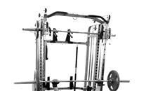
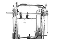
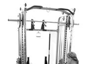
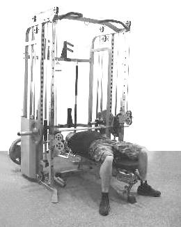
1 AX1001 Smith/Functional training Combo-free weight ASSEMBLY INSTRUCTIONS
2 EXPLODED DIAGRAM /
3 PART LIST NUMBER DESCRIPTION QUANTITY 1 LEFT BASE 1 2 RIGHT BASE 1 3 LEFT MAIN UPRIGHT 1 4 RIGHT MAIN UPRIGHT 1 5 REAR LEFT UPRIGHT 1 6 REAR RIGHT UPRIGHT 1 7 LEFT SLIDE FRAME 1 8 RIGHT SLIDE FRAME 1 9 GUIDE ROD 4 10 SHORT GUIDE ROD 2 11 PLATE SUPPORT 2 12 TOP FRAME 2 13 BOTTOM CROSS FRAME 1 14 MIDDLE CROSS FRAME 1 15 TOP CROSS FRAME 1 16 WEIGHT BAR 1 17 PULL BAR 1 18 LEFT SUPPORT 1 19 RIGHT SUPPORT 1 20 LEFT HOLD SUPPORT 1 21 RIGHT HOLD SUPPORT 1 22 LEFT BARBELL SUPPORT 1 23 RIGHT BARBELL SUPPORT 1 24 LEFT SLIDER 1 25 RIGHT SLIDER 1 26 DOUBLE PULLEY BRACKET 2 27 SLIDE SUPPORT 2 28 LEFT HOOK 1 29 RIGHT HOOK 1 30 BAR HOLDER 1 31 SINGLE PULLEY BRACKET 2 32 PLATE BAR 2 33 OLYMPIC PLATE BAR 6 34 SHORT OLYMPIC PLATE BAR 2 35 CLOSED HOOK 1 36 HOOK 4 37 ROTATION SUPPORT 1 38 BAR SUPPORT 1 39 AXIS 1 40 BUSHING 2 41 CIRCLE HOOK 2
4 42 REINFORCEMENT PLATE 4 43 REINFORCEMENT PLATE 6 44 M10 BOLT CAP 2 45 ROUND PLUG 8 46 RUBBER CIRCLE 8 47 RUBBER BUMPER 6 48 SPIRNG CLIP-REGULAR 8 49 SPIRNG CLIP-OLYMPIC 8 50 LOCK PIN 2 51 BEARING 2 52 CIRCLE FOR HOLE 2 53 PULLEY LARGE PULLEY 2 55 NYLON BUSHING 1 56 CLIP 2 57 CABLE 2 58 PLUM SHAPED SCREW 1 59 SLIDER PIN 2 60 M8*8 SOCKET SCREW 2 61 M10*16 SOCKET CAP SCREW 4 62 M10*25 SOCKET CAP SCREW M10*30 HEXAGONAL HEAD SCREW 2 64 M10*50 SOCKET CAP SCREW M10*70 SOCKET CAP SCREW M10*75 SOCKET CAP SCREW M10*105 SOCKET CAP SCREW 2 68 M12*105 SOCKET CAP SCREW 1 10MM WASHER MM WASHER 2 71 M8 LOCK NUT 2 M10 LOCK NUT M12 LOCK NUT 1 74 M12 NUT 2 83 HOLDER 2 84 PULL PIN 4 85 FOAM ROLLER 2 86 FOAM COVER 2 87 CABLE STOPPER WRENCH 1 89 ALLEN-WRENCH ALLEN-WRENCH ALLEN-WRENCH-10 1
5 STEP 01 1.Attach the right main upright (4) and reinforcement plate (43) to the right base (2) using two M10*75 screws (66), four 10mm washers () and two M10 lock nuts (). 2.Attach the rear right upright (6) and reinforcement plate (43) to the right base (2) using two M10*75 screws (66), four 10mm washers () and two M10 lock nuts (). 3.Attach the top frame (12) to the right main upright (4) using two M10*70 screws (65), two M10*16 screws (61), six 10mm washers () and two M10 lock nuts (). 4.The assembly step of left side is the same as the right one. (STEP 01)
6 STEP Attach the bottom cross frame (13) and reinforcement plate (42) to rear left and right upright (5 6) using four M10*70 screws (65), four M10*75 screws (66), sixteen 10mm washers () and eight M10 lock nuts (). 2. Attach the middle cross frame (14) and reinforcement plate (42) to rear left and right upright (5 6) and top frame (12) using four M10*75 screws (66), four M10*25 screws (62), twelve 10mm washers () and four M10 lock nuts (). 3. Attach the top cross frame (15) and reinforcement plate (43) to top frame (12) using four M10*70 screws (65), eight 10mm washers () and four M10 lock nuts (). 4. Attach the closed hook (35) to the top cross frame (15) using 10mm washers () and M10 lock nut (). 5. Insert one holder (83) into hole on the middle cross frame (14).
7 STEP Slide the left and right hook (28 29) onto the weight bar (16). 2. Slide the slide support (27) onto the weight bar (16). 3. Insert the short guide rod (10) into hole of the slide support (27) and rubber bumper (47), attach the short guide rod (10) to the left and right main upright (3 4) and the top frame (12) using four M10*70 screws (65) and four 10mm washers (). 4. Hook the left and right hook (28 29) to left and right main upright (3 4) and secure with M8*8 screw (60). 5. Slide the left and right slider (24 25) onto the left and right slide frame (7 8), secure with slider pin (59). 6. Attach the double pulley bracket (26) to the left and right slider (24 25) using bushing (40), two M10*105 screws (67), four 10mm washers () and two M10 lock nuts (). 7. Attach the left slide frame (7) to the left base (1) and top frame (12) using two M10*75 screws (66), four 10mm washers () and two M10 lock nuts (). 8. Attach the right slide frame (8) to the right base (2) and top frame (12) using two M10*75 screws (66), four 10mm washers () and two M10 lock nuts ().
 and the plate support (11) onto the guide rod (9).")
8 STEP Attach the bar holder (30) to rear left upright (5) using two M10*30 screws (63) and two 10mm washers (). Push the M10 bolt cap (44) onto screws (63). 2. Slide rubber bumper (47) and the plate support (11) onto the guide rod (9). Insert the guide rod (9) into hole of the left and right base (1 2) and secure the rod to the top frame (12) using four M10*70 screws (65) and four 10mm washers (). 3. Attach the plate bar (32) to the rear upright (5 6) using two M10*25 screws (62) and two 10mm washers (). 4. Slide the Olympic plate bar (33) onto the weight bar (16), the plate support (11) and the plate bar (32), secure with six M10*25 screws (62) and six 10mm washers (). Slide the short Olympic plate bar (34) onto the plate support (11), secure with two M10*25 screws (62) and two 10mm washers (). Push round plug (45) into Olympic plate bars (33 34). 5. Attach the hooks (36) to the bottom and middle cross frame (13 14) using four M10 lock nuts () and four 10mm washers (). 6. Thread a nut M12 (74) onto the singe pulley bracket (31). Insert the singe pulley bracket (31) into the plate support (11). Do not tighten! This will be adjusted later. 7. Attach sixteen pulley (53) and two large pulley (54) into the pulley brackets using eighteen screws M10*50 (64), thirty-six 10mm washers () and sixteen M10 lock nuts (). The top four pulleys have cable stopper (87).
 to the rotation support (37) using M12*105 screw (68), two 12mm washers (70) and M12 lock nut (73). 3. Attach the plum shaped screw (58) to the bar support (38). 4.")
9 STEP Attach the rotation support (37) and nylon bushing (55) to main upright (3 4) or slide frame (7 8) use axis (39). Then lock with lock pin (50). 2. Attach the bar support (38) to the rotation support (37) using M12*105 screw (68), two 12mm washers (70) and M12 lock nut (73). 3. Attach the plum shaped screw (58) to the bar support (38). 4. Attach the left and right barbell support (22 23), the left and right hold support (20 21) and the left and right support (18 19) to slide frame (7 8). 5. Lock the left and right barbell support (22 23), the left and right hold support (20 21) with pull pin (84).
10 STEP 06 Bring the threaded end of the cable (57) from A B C D E F G H 24. NOTE: From F G, the cable is IN the tube. Repeat the steps to route the cable through the right tower. Attach the pull bar (17) to cables (57) with clip (56). Hi, when you assembled till now, congratulation, your assembly works are finished for the item. For the item we have an upgrading one which can add weight plates and cover if you need in future. Please check the following steps if you want to upgrade in future. Here we supply you the additional screws as a gift, thanks for you to buy the gym.


11 HOME FITNESS GYM WITH PLASTIC WEIGHTS

12 PART LIST NUMBER DESCRIPTION QUANTITY 62 M10*25 SOCKET CAP SCREW 4 10MM WASHER 4 75 SELECTOR SHARFT 2 76 PLASTIC WEIGHT PLATE TOP PLATE 2 78 SIDE SHELL 2 79 LARGE WASHER 2 80 PLASTIC CIRCLE 2 81 PIN 2 82 SELECTOR PIN 2
 to left and right main upright (3 4) using four M10*25 screws (62) and four 10mm washers (). 3.")
 and the plastic weight plate (76) onto the guide rod (9). Insert the selector sharft (75) into mid hole of the plastic weight plate (76).")
13 1. If you want to use the plastic weight system, the assembly steps is the same as the bell piece system (STEP 01-06). But it is different on STEP Attach the side shell (78) to left and right main upright (3 4) using four M10*25 screws (62) and four 10mm washers (). 3. Attach the side shell (78) to rear left and right upright (5 6) using screws on bottom cross beam (13). 4. Insert the guide rod (9) into holes on the left and right base (1 2). 5. Slide rubber bumper (47) and the plastic weight plate (76) onto the guide rod (9). Insert the selector sharft (75) into mid hole of the plastic weight plate (76). Attach the plastic circle (80) and the pin (81) to the first hole of selector sharft (75). Slide the top plate (77) onto the guide rod (9). 6. Attach the guide rod (9) to the top frame (12) using four M10*70 screws (65) and four 10mm washers (). 7. Thread a nut M12 (74) onto the singe pulley bracket (31). Insert the singe pulley bracket (31) into the selector sharft (75). Do not tighten! This will be adjusted later.


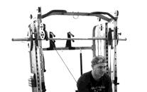
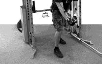


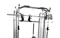


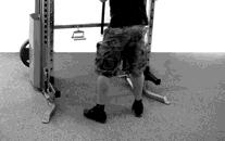
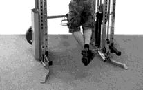
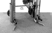

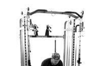
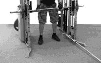
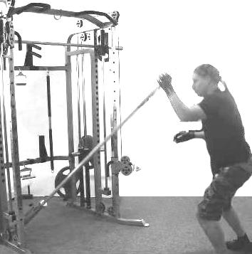
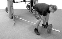
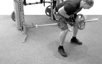
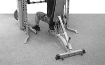
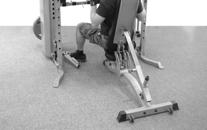
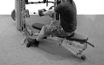
14 EXERCISES START FINISH START FINISH


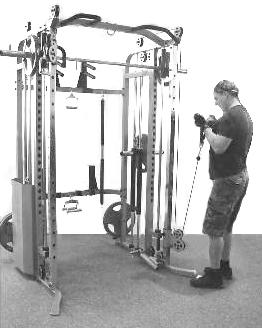
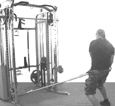
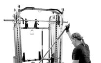


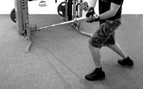

15 START FINISH START FINISH


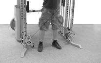
16 START FINISH START FINISH

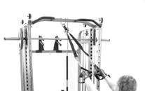
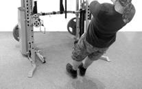
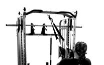


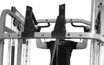

17 START FINISH START FINISH
OWNERS MANUAL MODEL F660 HIP SLED
 OWNERS MANUAL MODEL F HIP SLED QUESTION? As a quality home gym supplier we are committed to your complete satisfaction. If you have questions, or find missing or damaged parts, we will guarantee your complete
PFT CABLE GYM INSTRUCTION MANUAL
 PFT CABLE GYM INSTRUCTION MANUAL QUESTION? As a quality home gym supplier we are committed to your complete satisfaction. If you have questions, or find missing or damaged parts, we will guarantee your
This manual will aid in the assembly of the FireBall V90 and FireBall X90. The assembly of both machines will be identical, unless specified.
 This manual will aid in the assembly of the FireBall V90 and FireBall X90. The assembly of both machines will be identical, unless specified. Step #1 Lay all parts out to verify quantities. (2) 2 x 25-1/4
SMITH STRENGTH TRAINING SYSTEM INSTRUCTION MANUAL MODEL : F410
 SMITH STRENGTH TRAINING SYSTEM INSTRUCTION MANUAL MODEL : F0 QUESTION? As a quality home gym supplier we are committed to your complete satisfaction. If you have questions, or find missing or damaged parts,
INSTRUCTION MANUAL LEG PRESS OPTION OF ELITE GYM
 INSTRUCTION MANUAL LEG PRESS OPTION OF ELITE GYM QUESTION? As a quality home gym supplier we are committed to your complete satisfaction. If you have questions, or find missing or damaged parts, we will
LifeGear G1 /HOME GYM ITEM NO.: 63100
 LifeGear G1 /HOME GYM ITEM NO.: 63100 OWNER S MANUAL IMPORTANT: Read all instructions carefully before using this product. Retain this owner s manual for future reference. The specifications of this product
Serial Number Location
 GL/GLX STRENGTH TRAINING SYSTEM OWNERS MANUAL Serial Number Location SERIAL 3 4 5 7 8 Record your Serial number and purchase date here: S/N DATE: DEALER: Model No. BCG-GL BODYCRAFT is a division of Recreation
CFT STRENGTH TRAINING SYSTEM OWNER'S MANUAL
 CFT STRENGTH TRAINING SYSTEM OWNER'S MANUAL Serial Number Location SERIAL 8 Record your Serial number and purchase date here: S/N PURCH.DATE: DEALER: Scan this QR code with your PortableDevice to link
PHG-1000X. Owner s Manual HOME GYM
 HOME GYM Owner s Manual WWW.BODYSOLID.COM THERE IS A RISK ASSUMED BY INDIVIDUALS WHO USE THIS TYPE OF EQUIPMENT. TO MINIMIZE RISK, YOU MUST FOLLOW THESE RULES:! " # $ % & ' ( ) * + ' (, ' " -. *, * ) )
STRATA STRENGTH TRAINING SYSTEM INSTRUCTION MANUAL
 STRATA STRENGTH TRAINING SYSTEM INSTRUCTION MANUAL QUESTION? As a quality home gym supplier we are committed to your complete satisfaction. If you have questions, or find missing or damaged parts, we will
COMPETITOR CB-610 STANDARD BENCH
 NOTE: Please read all instructions carefully before using this product Table of Contents Safety Notice COMPETITOR CB-610 STANDARD BENCH Hardware Identifier Assembly Instruction Exploded Diagram Parts List
Assembly & Operating Instructions Ironmaster IM1500
 Assembly & Operating Instructions Ironmaster IM1500 The IM1500 half cage is designed for barbell training with spotting capabilities. The IM1500 is designed to be used in conjunction with Ironmaster products,
Removing the Z-Axis lead screw
 Page 1 of 8 TITLE: Sabre Z-Axis Lead Screw Replacement Procedure Gerber FastFact #: 5048 Supplied by: Gerber Hardware Support Last Modified: June 14, 2007 Summary: Tools used: The following procedure explains
M2 Assembly. M2 Sub-Assemblies mm Belt Sub-Assembly mm Belt Sub-Assembly Spider Sub-Assembly... 4
 M2 Assembly Table of Contents M2 Sub-Assemblies... 3 630mm Belt Sub-Assembly... 3 702mm Belt Sub-Assembly... 3 Spider Sub-Assembly... 4 Idler Bolt Sub-Assembly... 8 Y Motor Sub-Assembly... 9 X Motor Sub-Assembly...
Technical Procedure. HIITMill (X) Push/Pull Brake Cable Install
 Push/Pull Brake Cable Install") HIITMill (X) Push/Pull Brake Cable Install Applies to: HIITMill and HIITMill X Required Tools: 2.5mm Allen Key 3mm Allen Key 4mm Allen Key 5mm Allen Key 6mm Allen Key 10mm Wrench 10mm Socket Ratchet Needle
HIITMill (X) Push/Pull Brake Cable Install Applies to: HIITMill and HIITMill X Required Tools: 2.5mm Allen Key 3mm Allen Key 4mm Allen Key 5mm Allen Key 6mm Allen Key 10mm Wrench 10mm Socket Ratchet Needle
OWNER S MANUAL. Dual Adjustable Pulley Machine. Model #: N820 DP
 OWNER S MANUAL Dual Adjustable Pulley Machine! Model #: N820 DP Caution: Read all precautions and instructions in this manual before using this equipment. Save this manual for future reference. Contents
Olympic Bench Model 6600
 Olympic Bench Model 6600 IMPORTANT SAFETY INSTRUCTIONS TKO Fitness products are designed and manufactured to the highest standards in order to provide you with years of great workouts. We proudly stand
HOME GYM Owner s Manual
 HOME GYM Owner s Manual Content Content-------------------------------------------------------------1 Safety precautions----------------------------------------------------2 Assembly instruction-------------------------------------------------3-12
Rugged Ridge 2 Receiver Hitch Kit (J21068)
") Rugged Ridge 2 Receiver Hitch Kit (J21068) Installation Time: 1-2 Hours Tools Required: ¾ Open End Wrench 18 mm Socket ¼ drive Pliers/Needle nose pliers/channel locks, etc. Torque wrench Phillips head
Rugged Ridge 2 Receiver Hitch Kit (J21068) Installation Time: 1-2 Hours Tools Required: ¾ Open End Wrench 18 mm Socket ¼ drive Pliers/Needle nose pliers/channel locks, etc. Torque wrench Phillips head
DUAL ADJUSTABLE PULLEY IP-D9302 INSTALLATION INSTRUCTIONS
 DUAL ADJUSTABLE PULLEY IP-D9302 INSTALLATION INSTRUCTIONS Copyright 2010. Star Trac by Core Industries, Inc. All rights reserved, including those to reproduce this book or parts thereof in any form without
POWER RACK STRENGTH TRAINING SYSTEM INSTRUCTION MANUAL MODEL : F430 POWER RACK
 POWER RACK STRENGTH TRAINING SYSTEM INSTRUCTION MANUAL MODEL : F0 POWER RACK QUESTION? As a quality home gym supplier we are committed to your complete satisfaction. If you have questions, or find missing
STRATA STRENGTH TRAINING SYSTEM INSTRUCTION MANUAL
 STRATA STRENGTH TRAINING SYSTEM INSTRUCTION MANUAL QUESTION? As a quality home gym supplier we are committed to your complete satisfaction. If you have questions, or find missing or damaged parts, we will
Xceed ASSEMBLY MANUAL
 Xceed ASSEMBLY MANUAL Table of Contents / Registration Congratulations on your commitment to fitness and your purchase of the Bowflex Xceed home gym. Before assembling your Bowflex Xceed home gym please
INSTALLATION INSTRUCTIONS DODGE RAM 2 & 4WD 1500 PART # P5058
 INSTALLATION INSTRUCTIONS 2009-13 DODGE RAM 2 & 4WD 1500 PART # P5058 PARTS LIST: Qty Description Qty Description 1 Grille Guard 12 12-1.75mm Hex Nuts 2 Upper Frame Mounting s (for trucks without tow hooks
The Bowflex Revolution XP Home Gym Assembly Instructions. P/N: Rev ( /0 )
") P/N: 001-7057 Rev ( /0 ) The Bowflex Revolution XP Home Gym Assembly Instructions 2 Table of Contents Before You Start... 2 Tools You Will Need / Hardware Contents... 3 Box Contents... 6 Assembling Your
P/N: 001-7057 Rev ( /0 ) The Bowflex Revolution XP Home Gym Assembly Instructions 2 Table of Contents Before You Start... 2 Tools You Will Need / Hardware Contents... 3 Box Contents... 6 Assembling Your
INSTALLATION INSTRUCTIONS GRILLE GUARD RAM 1500 PART # 5058/5058-2
 INSTALLATION INSTRUCTIONS GRILLE GUARD PART # 5058/5058-2 PARTS LIST: Qty Description Qty Description 1 Grille Guard 8 12-1.75mm x 35mm Hex Bolts 2 Upper Frame Mounting s (for trucks without tow hooks
AUTOMATIC ADVANCE MANUAL
 AUTOMATIC ADVANCE MANUAL AVL Looms, Inc. 3851 Morrow Lane, Suite #9 Chico, CA 95928-8305 530 893-4915 530 893-1372 fax # info@avlusa.com www.avlusa.com Copyright 2009 TABLE OF CONTENTS Page # I. Parts.........................
Medium HoneyBadger Chase Rack Installation Instructions
 PREPARATION Medium HoneyBadger Chase Rack Installation Instructions 1. Disconnect the negative terminal on the battery. Park the vehicle on level ground and set the emergency brake. 2. We recommend reading
MAG-CONV Basic, 48, 48R & Midline Front Mount
 Parts Required: Tools Used: Mag Wheels Brakes Brake Rods Mounting Bracket Anti Tippers 7/16" Wrench Screw Driver Rubber Mallet 5/8 Wrench 5mm Allen Wrench Step Execution Figures 1 Remove front 5" total
INSTALLATION INSTRUCTIONS
 TEL:1-866-XANATOS INSTALLATION INSTRUCTIONS FOR 2017-2018 NISSAN TITAN (EXCLUDES TITAN XD MODELS) PART#AB-NI20 PARTS LIST: 1 Bull Bar 2 8mm Nylon Lock Nuts 1 Driver/Left Side Bull Bar Bracket 2 8-1.25mm
set of safety brace steel cable draw-up gate kpl
 0324101 7108020 8208100 Order-nr. Description Number 0324101 safety brace steel cable draw-up gate 2 7108020 hexagon-head tap bolt M8x20 galv. 2 8208100 hexagon nut M8 galv. 2 set of safety brace steel
Authority22 Transition Roller for Existing Machines
 Authority22 Transition Roller for Existing Machines Upgrade Packaging 1 per Authority22 14-860241-000 Package Transition Roller Upgrade Kit NOTE: Due to installation requirements, the parts will be packaged
A s s e m b l y I n s t r u c t i o n s
 by Body-Solid A s s e m b l y I n s t r u c t i o n s Be careful to assemble all components in the sequence they are presented. NOTE: Finger tighten all hardware in this step. Do Not wrench tighten until
Star Trac Turbo Trainer Assembly & Setup
 Star Trac Turbo Trainer Use the following procedures to unpack and assemble your Turbo Trainer manufactured by Star Trac. UNPACKING AND PARTS LIST Position the shipping carton so the Heavy End logo is
Ford Raptor Venom Front Bumper Installation Instructions
 PREPARATION 2010 2014 Ford Raptor Venom Front Bumper Installation Instructions 1. Disconnect the negative terminal on the battery. Park the vehicle on level ground and set the emergency brake. 2. We recommend
TIRE RACK INSTALLATION INSTRUCTIONS Dodge Sprinter
 Aluminess Products Inc 9402 Wheatlands Ct. #A Santee, CA 92071 619-449-9930 TIRE RACK INSTALLATION INSTRUCTIONS 07-11 Dodge Sprinter Please read before beginning Stainless steel hardware may bind together
25-200H. 12 Planer / Jointer. with Helical Cutterhead. Parts List.
 25-200H 12 Planer / Jointer with Helical Cutterhead 4001824 Parts List www.rikontools.com CABINET ASSEMBLY PARTS EXPLOSION & PARTS LIST KEY NO. DESCRIPTION KEY NO. DESCRIPTION 1 Pan Head Screw M6x12 P25-200H-1
GRILLE GUARD SPRINTER VAN (EXCLUDES X4) INCLUDES MERCEDES, FREIGHTLINER AND DODGE PARTS LIST:
 INCLUDES MERCEDES, FREIGHTLINER AND DODGE PARTS LIST:") PARTS LIST: 1 Grille Guard 8 12mm Hex Nuts 1 Driver/Left Side Frame Mounting Bracket 2 10-1.50mm x 25mm Button Head Bolts 1 Passenger/Right Side Frame Mounting Bracket 4 10mm x 20mm OD x 2mm Flat Washers
PARTS LIST: 1 Grille Guard 8 12mm Hex Nuts 1 Driver/Left Side Frame Mounting Bracket 2 10-1.50mm x 25mm Button Head Bolts 1 Passenger/Right Side Frame Mounting Bracket 4 10mm x 20mm OD x 2mm Flat Washers
TYGER GUARD. Parts List BEFORE INSTALLATION WARNING TG-GD6D /7. Tyger Guard. Tube Brackets (Bull Bar) passenger or driver side
 passenger or driver side") TYGER GUARD TM BEFORE INSTALLATION TG-GD6D60068 READ INSTRUCTIONS CAREFULLY BEFORE STARTING INSTALLATION. REMOVE CONTENTS FROM BOX AND VERIFY ALL PARTS ARE PRESENT. ASSISTANCE IS RECOMMENDED. CUTTING IS
TYGER GUARD TM BEFORE INSTALLATION TG-GD6D60068 READ INSTRUCTIONS CAREFULLY BEFORE STARTING INSTALLATION. REMOVE CONTENTS FROM BOX AND VERIFY ALL PARTS ARE PRESENT. ASSISTANCE IS RECOMMENDED. CUTTING IS
HQ Pole Upgrade Kit for HQ Adjustable Table and HQ QuilTable Assembly Instructions 1
 HQ Pole Upgrade Kit for HQ Adjustable Table and HQ QuilTable Assembly Instructions QF09775 The pole upgrade kit can be used with or without the QF09700 HQ Precison-Glide track upgrade kit. What s Included
SPARE PARTS LIST MODEL NO. LB1200F PAGE 1 ITEM PART NO. DESCRIPTION QTY NOTE
 PAGE 1 001 JM21000018 HEX.SOCKET HEAD SCREW M5X12 4 002 JM21000019 SPRING WASHER 5 4 003 JM21000020 FLAT WASHER 5 4 004 JM21000021 UP COVER COMPLETE 1 005 JM21000025 MICRO SWITCH FIX PANEL A 1 006 JM21000026
INSTALLATION INSTRUCTIONS
 INSTALLATION INSTRUCTIONS SPORTSMAN WINCH MOUNT GRILLE GUARD APPLICATION: 2016-2018 Toyota Tacoma PART NUMBER: 40-93885, 45-93880, 46-23885 ITEM QUANTITY DESCRIPTION TOOLS NEEDED 1 1 WINCH TRAY 15MM SOCKET
Deluxe Inversion Table SF-1201
 Deluxe Inversion Table SF-1201 Take a few moments to familiarize yourself with the specific parts and hardware included with your product. Make sure all the parts and hardware are included in the carton
TITAN2-EDGE Public Access Computer Station Dual Track
 TITAN2-EDGE Public Access Computer Station Dual Track TITAN2-EDGE Rev A 6/17 Model TITAN2-EDGE ASSEMBLY AND ADJUSTMENT TITAN2-EDGE PARTS AND TOOLS PLEASE REVIEW these instructions before beginning the
A SSEMBLY INSTRUCTION MAN UAL
 A SSEMBLY INSTRUCTION MAN UAL TABLE OF CONTENTS: Introduction- Pg. 1 Assembly for TG-150- Fig. 1-71 Cable Mapping Diagram- Pg. 20 Cable Adjustments- Fig. 42, 65, Pg. 19 Exploded View Diagram- Pg. 22 Parts
Hardware and Components:
 Hardware and Components: (A) 4X 5/16 x 1 Carriage Bolt (B) 2X 5/16 x 2-1/4 Carriage Bolt (C) 2X 5/16 x 3-1/4 Hex Bolt (D) 2X 5/16 x 3/4 Hex Bolt (E) 2X 5/16 x 1-1/4 Hex Bolt (F) 5/16 x 2-1/4 Hex Bolt (G)
Hardware and Components:
 Hardware and Components: (A) 5/16 x 2 Hex Bolt (B) 5/16 x 2-1/4 Hex Bolt (C) 5/16 x 2-1/2 Hex Bolt (D) 4X 5/16 x 3/4 Hex Bolt (E) 4X 5/16 x 1-1/4 Hex Bolt (F) 11X 5/16 Flat Washer (G) 12X 5/16 Nylock Nut
ABM International, Inc. Navigator Assembly Manual
 ABM International, Inc. 1 1.0: Parts List Tablet (Qty. 1) Tablet mount (Qty. 1) NOTE: Mount may appear and operate different then image below Control Box (Qty. 1) Motor Power Supply (Qty. 1) 2 X-axis motor
PORTA~TRACE. GAGNE, INC. 41 Commercial Dr. Johnson City, New York Phone: Fax: ASSEMBLY INSTRUCTIONS
 PORTA~TRACE GAGNE, INC. 41 Commercial Dr. Johnson City, New York 13790 Phone: 1-607-729-3366 Fax: 1-607-729-7644 ASSEMBLY INSTRUCTIONS PORTA~TRACE MODEL 2436T LIGHT TABLE PORTA~TRACE MODEL 3648T LIGHT
XHD Bull Bar w/ Dual Row LED Light Bar (10-17 Jeep JK)
") XHD Bull Bar w/ Dual Row LED Light Bar (10-17 Jeep JK) PARTS LIST: 1 Driver/Left Side Bull Bar Upright 8 10-1.5mm Hex Nuts 1 Side Bull Bar Upright 4 10-1.5mm Nylon Lock Nuts 1 Top Cross Bar 2 Light Bar
XHD Bull Bar w/ Dual Row LED Light Bar (10-17 Jeep JK) PARTS LIST: 1 Driver/Left Side Bull Bar Upright 8 10-1.5mm Hex Nuts 1 Side Bull Bar Upright 4 10-1.5mm Nylon Lock Nuts 1 Top Cross Bar 2 Light Bar
ABM International, Inc.
 ABM International, Inc. Lightning Stitch required 1 1.0: Parts List head and motor assembly (Qty. 1) Reel stand (Qty. 1) Needle bar frame clamp (Qty. 1) Motor drive (Qty. 1) 2 Cable harness with bracket
ASSEMBLY INSTRUCTIONS JK270
 TOOLS REQUIRED: One knife to open packaging Two ½ wrench or socket (metric 13) One 9/16 wrench or socket (metric 14) One #2 Philips (+) screwdriver NOTE: All bolts are 9/16 (metric 14) and nuts are ½ (metric
SIGNATURE FRONT BUMPER INSTALL
 SIGNATURE FRONT BUMPER INSTALL JL **PLEASE READ THROUGH THE INSTRUCTIONS BEFORE BEGINNING ANY PART OF THE INSTALLATION PROCESS** 1. You can now remove the trim strip (2 vertical clips, 4 horizontal, 2
FRONT AND REAR HOOD ASSEMBLY (GRAIN CART) REF PART# DESCRIPTION QTY RETAIL
 REF PART# DESCRIPTION QTY RETAIL") FRONT AND REAR HOOD ASSEMBLY (GRAIN CART) 1 0001-014311 GRAIN CART STEEL FRONT HOOD 1 1A 0001-014313 GRAIN CART 5" OFFSET STEEL FRONT HOOD 1 2 0001-014312 GRAIN CART STEEL REAR HOOD 1 N/A 0001-014901 GRAIN
FRONT AND REAR HOOD ASSEMBLY (GRAIN CART) 1 0001-014311 GRAIN CART STEEL FRONT HOOD 1 1A 0001-014313 GRAIN CART 5" OFFSET STEEL FRONT HOOD 1 2 0001-014312 GRAIN CART STEEL REAR HOOD 1 N/A 0001-014901 GRAIN
INSTALLATION INSTRUCTIONS 1PC FRONT BUMPER JEEP JK WRANGLER
 INSTALLATION INSTRUCTIONS PARTS LIST: 1 1PC Bumper 2 8mm x 25mm Hex Bolts 1 Bull Nose Hoop 2 8mm x 16mm Hex Bolts 1 Fairlead Mounting Bracket 6 8mm x 24mm x 2mm Flat Washers 8 12mm x 35mm Hex Bolts 4 8mm
/ Rudder Installation Guide
 / Rudder Installation Guide Parts List Part # Part Description Qty Part # Part Description Qty 1030 Plastic Bead 1 1195 Rope; 1/8" Black Nylon 1 @ 9 1044 1/4-20 x 5/8" Pan Head Bolt 2 1353 Sliding Track
Code Product Qty 1 Top Vertex 3 2 Hot End Housing 1 3 Bottom Vertex 3 4 Print Platform Lock 3 5 End Stop Holder 3 6 Filament Feeder Motor Bracket 1 7
 List of Parts Code Product Qty 1 680mm Extrusion 3 2 Power Supply 1 3 240mm Extrusion 9 4 42mm Nema 17 Stepper Motor 3 5 Slider-Hotend Connecting Rod 6 6 48mm Nema 17 Stepper Motor 1 7 Linear Rail with
MODULAR BUMPER INSTALLATION MANUAL
 MODULAR BUMPER INSTALLATION MANUAL Parts List* 1 Center section 1 Side extension, passenger / right 1 Side extension, driver / left 1 Side cap, passenger / right 1 Side cap, driver / left 1 Brush guard,
COMPETITOR WM-203 COMBO BENCH
 NOTE: Please read all instructions carefully before using this product Table of Contents Safety Notice Hardware Identifier COMPETITOR WM-203 COMBO BENCH Assembly Instruction Exploded Diagram Parts List
Front axle components, overview
 j a t Front axle components, overview 40-1 General Information Load bearing components and parts of the suspension must not be welded or straightened. Vehicles without drive axle must not be moved, or
SECTION 9: PARTS. Table Breakdown REF PART # DESCRIPTION REF PART # DESCRIPTION
 SECTION 9: PARTS Table Breakdown 1 2 3 4 5 6 7 8 9 10 11 12 13 14 15 16 17 18 19 20 21 22 23 24 23 25 17 26 27 8 1 P0675001 CAP SCREW M8-1.25 X 30 15 P0675015 SUPPORT BLOCK 2 P0675002 TABLE SUPPORT BLOCK
RYOBI. 10 in. (254 mm) TABLE SAW MODEL NO. BTS15 REPAIR SHEET
 TABLE SAW MODEL NO. BTS15 REPAIR SHEET") RYOBI 0 in. ( mm) TABLE SAW MODEL NO. BTS REPAIR SHEET FIGURE A 0 0 0 0 The model number will be found on a plate attached to the motor housing. Always mention the model number in all correspondence regarding
RYOBI 0 in. ( mm) TABLE SAW MODEL NO. BTS REPAIR SHEET FIGURE A 0 0 0 0 The model number will be found on a plate attached to the motor housing. Always mention the model number in all correspondence regarding
CRP700 Benchtop Basic CNC Machine Assembly Instructions. Updated 9/11/2014 SHEET 1 of 25
 CRP700 Benchtop Basic CNC Machine Assembly Instructions Updated 9//0 SHEET of NOTE: This piece of extrusion is mounted wide side up Quick Tip: Lay extrusion on table as shown for easy assembly BASE ASSEMBLY:.
INSTALLATION INSTRUCTIONS
 TEL:1-866-XANATOS INSTALLATION INSTRUCTIONS FOR 07-13 CHEVY SILVERADO 1500 PART#RU-CHSI07-B PARTS LIST: 1 Main Body 28 12mm x 37mm OD x 3mm Large Flat Washers 1 Driver/Left Brush Guard 8 12-1.75mm x 40mm
Calf-Tel Pen System Assembly Instructions
 Calf-Tel Pen System Assembly Instructions (Instructions work for 4, 6, and the 7 Pen Systems) 1 ASSEMBLY OF PEN FRONT AND WALLS START THE ASSEMBLY BY LINING UP THE TWO UNI-DIRECTIONAL ARROWS IN THE TOP,
Rough Country JK Modular Winch Mount Bumper With Light End Caps
 Rough Country JK Modular Winch Mount Bumper With Light End Caps Note: These instructions involve cutting parts of your vehicle. Please read all instructions prior to starting. Note: This installation also
MARCY CLASSIC MCB-252 COMBO BENCH W/120 lbs Weight Set
 NOTE: Please read all instructions carefully before using this product Table of Contents Safety Notice Hardware Identifier Assembly Instruction MARCY CLASSIC MCB-252 COMBO BENCH W/120 lbs Weight Set Exploded
OWNER S MANUAL AMERICA S PREMIER EXERCISE EQUIPMENT RHL-305WS. High/Low Pulley W/200 Lbs Steel Wt Stack (for RPR-265) 84" 59" 50 3/4"
 84 59 50 3/4") OWNER S MANUAL 84" RHL-0WS 0 /4" 9" High/Low Pulley W/200 Lbs Steel Wt Stack (for RPR-26) AMERICA S PREMIER EXERCISE EQUIPMENT RHL-0WS Rev0 Revision Date -0-2007 Introduction About the RHL-0WS High/Low
OWNER S MANUAL 84" RHL-0WS 0 /4" 9" High/Low Pulley W/200 Lbs Steel Wt Stack (for RPR-26) AMERICA S PREMIER EXERCISE EQUIPMENT RHL-0WS Rev0 Revision Date -0-2007 Introduction About the RHL-0WS High/Low
2017 Current Ford Raptor ADD Pro Front Bumper Installation Instructions
 2017 Current Ford Raptor ADD Pro Front Bumper Installation Instructions PREPARATION 1. Disconnect the negative terminal on the battery. Park the vehicle on level ground and set the emergency brake. 2.
INSTALLATION INSTRUCTIONS
 Do not attempt to install this product on any vehicle other than the one it is designed for and listed above! Parts List 10 3/8 X 1 1/4 Hex Bolt 10 3/8 Lock Washer 4 3/8 Hex Nut 4 3/8 Flat Washer 2 3169)
USER MANUAL EN IN 9306 Home Gym insportline ProfiGym C95
 USER MANUAL EN IN 9306 Home Gym insportline ProfiGym C95 1 CONTENTS PARTS LIST... 3 EXPLODED-VIEW... 5 ASSEMBLY INSTRUCTIONS... 6 TERMS AND CONDITIONS OF WARRANTY, WARRANTY CLAIMS... 20 2 PARTS LIST 3
RYOBI 10 in. TABLE SAW - MODEL NO. BT3000
 FOR MITER TABLE ASSEMBLY, REFER TO FIGURE 0 RYOBI 0 in. TABLE SAW - MODEL NO. BT000 FIGURE 5: 0 in. TABLE SAW FOR BLADE GUARD ASSEMBLY, REFER TO FIGURE FOR RIP FENCE ASSEMBLY, REFER TO FIGURE FOR MOTOR
RBP-1215B-RX DODGE RAM QUAD CAB RX3
 RBP-1215B-RX3 2002-2017 DODGE RAM 15-3500 QUAD CAB RX3 Passenger side RX-3 Side Step Drill Template Passenger side rear Modular Bracket (6) L Support Brackets Driver side rear Modular Bracket Driver side
Jenny Legs Assembly Instructions
 Jenny Legs Assembly Instructions R EXTENDED PHILLIPS BIT MM ALLEN WRENCH 6MM HEX DRIVE /" 007 Steelcase Inc. Grand Rapids, MI 90 U.S.A. Printed in U.S.A. Page of 6 88000 Rev F Jenny Club Instructions:
55000/55010 Installation Instructions
 A. Install 55015 B. Bolt roof rails, 55020/55025, to front hoop. C. Assemble 55026 D. To install without drilling into bumper. E. If mounting directly to bumper. A. 55015 Installation Instructions 55000/55010
For additional assistance call
 The following pages will help guide you through the process of assembling your new 48 custom prize wheel. Choose an assembly area with plenty of room to lay your pieces on the floor and also a bench or
Retractable Tongue Kit Model MPG457 Instructions
 Malone MicroSport Trailer Retractable Tongue Kit Model MPG457 Instructions TM Take a few moments and read through these instructions to familiarize yourself with the step by step assembly process before
Section E SWEEP WAGON
 Section E SWEEP WAGON 1E 2E Index No. Part No. Description 1. 47-042058-002 Sweep Wagon Frame with Leaf Springs N.A. Sweep Wagon Frame without Leaf Springs 2. 47-041769-003 Sweep Board Only (brown for
ODY-5. Odyssey Home Gym TABLE OF CONTENTS: Introduction - Pg. 1. Safety Precautions - Pg. 2. Assembly for ODY-5 - Pg. 3 - Pg. 18, Pg.
 TABLE OF CONTENTS: Introduction - Pg. 1 Safety Precautions - Pg. 2 O W N E R S M A N U A L Assembly for ODY-5 - Pg. 3 - Pg. 18, Pg.20 Cable Adjustments - Pg. 19 Cable Mapping Diagram - Pg. 21 - Pg. 24
The Bowflex Blaze Home Gym Assembly Manual
 The Bowflex Blaze Home Gym Manual P 001-6903 Rev A (4/2006) Safety Precautions 1 Get to Know Your Machine 2 Basic Principles 3 Parts List 3 Hardware List 3 Accessory List 3 Hardware Guide 4 Tools You Will
mila-wall (Series100) General Operating Instructions page 1 of 15
 General Operating Instructions page 1 of 15") mila-wall (Series100) General Operating Instructions page 1 of 15 Step #1: Before setting up walls, lower adjustable leveling feet on each panel approximately 1". This will allow access to the threaded
mila-wall (Series100) General Operating Instructions page 1 of 15 Step #1: Before setting up walls, lower adjustable leveling feet on each panel approximately 1". This will allow access to the threaded
1503 Follow Spot Yoke, Source Four LED
 1503 Follow Spot Yoke, Source Four LED Rev 1.0 2016 City Theatrical, Inc. Getting Started with the City Theatrical Follow Spot Yoke for source four LED Congratulations on the purchase of your City Theatrical
Repair Instructions. Replacing a La Z Time Mechanism Side Subassembly. Remove the Back(s): Remove the Mechanism Assembly: CAUTION.
: Remove the Mechanism Assembly: CAUTION.") Replacing a La Z Time Mechanism Side Subassembly Tools Required: Slotted Screwdriver Power Driver 8" Driver Extension Ruler Note: Extension springs are not typically used on non-chaise standard width styles,
Replacing a La Z Time Mechanism Side Subassembly Tools Required: Slotted Screwdriver Power Driver 8" Driver Extension Ruler Note: Extension springs are not typically used on non-chaise standard width styles,
O-Sullivan King 4 Poster Bed O-Sullivan Queen 4 Poster Bed Parts and Hardware List
 Parts and Hardware List A. Left Headboard Post 1 pc B. Right Headboard Post 1 pc C. Left Footboard Post 1 pc D. Right Footboard Post 1 pc E. Headboard Panel 1 pc F. Footboard Rail 1 pc. Spindles 4 pcs
INSTALLATION GUIDE TOYOTA 4 RUNNER (2013+) REAR BUMPER
 REAR BUMPER") INSTALLATION GUIDE TOYOTA 4 RUNNER (2013+) REAR BUMPER CONTENTS CONTENTS Rear Bumper (base or dual arm) Installation...................................... 2 Dual Swing Installation..........................................................
INSTALLATION GUIDE TOYOTA 4 RUNNER (2013+) REAR BUMPER CONTENTS CONTENTS Rear Bumper (base or dual arm) Installation...................................... 2 Dual Swing Installation..........................................................
F l a t S c r e e n A R M S I n s t a l l a t i o n
 ITEM NUMBERS (1) #TOACAORG16 (2) #TOACAORG20 (3) #TOACATRP24 (4) #TOACATRP30 (5) #TOACATRPDS (6) #TOACATRPSS TOOLS REQUIRED (1) 3/8 Wrench (not provided) (2) Phillips head screwdriver (not provided) (1)
Bunk Pod Front Entry Assembly Instructions
 Bunk Pod Front Entry Assembly Instructions www.podtime.co.uk enquiries@podtime.co.uk Working House Ltd How to assemble your pod This step by step guide will show how to assemble your pod(s) on site. It
BY ALIEN TECHNOLOGIES CORP
 BY ALIEN TECHNOLOGIES CORP Assembly Instructions TopLift Pros YOU MAY ALSO REVIEW OUR ASSEMBLY VIDEO, PLAY AND PAUSE AT YOUR CONVENIENCE. JUST VISIT US AT WWW.TOPLIFTPROS.COM AND GO TO Customer Support
CHICKEN COOP & CHICKEN RUN. Tools required for assembly (not included)
") CHICKEN COOP & CHICKEN RUN ASSEMBLY MANUAL SKU# 6839 Tools required for assembly (not included) Distributed by: TRACTOR SUPPLY COMPANY 0 VIRGINIA WAY, BRENTWOOD, TN 3707 For customer support, call: -888-376-960
CHICKEN COOP & CHICKEN RUN ASSEMBLY MANUAL SKU# 6839 Tools required for assembly (not included) Distributed by: TRACTOR SUPPLY COMPANY 0 VIRGINIA WAY, BRENTWOOD, TN 3707 For customer support, call: -888-376-960
RYOBI 10 IN (254 MM) TABLE SAW MODEL NO. BT REPAIR SHEET
 TABLE SAW MODEL NO. BT REPAIR SHEET") RYOBI 0 IN (2 MM) TABLE SAW MODEL NO. BT00- REPAIR SHEET 2 RYOBI 0 in. (2 mm) TABLE SAW - MODEL NO. BT00- FOR MITER TABLE ASSEMBLY, REFER TO FIGURE B FOR BLADE GUARD ASSEMBLY, REFER TO FIGURE E FOR RIP
RYOBI 0 IN (2 MM) TABLE SAW MODEL NO. BT00- REPAIR SHEET 2 RYOBI 0 in. (2 mm) TABLE SAW - MODEL NO. BT00- FOR MITER TABLE ASSEMBLY, REFER TO FIGURE B FOR BLADE GUARD ASSEMBLY, REFER TO FIGURE E FOR RIP
INSTALLATION INSTRUCTIONS GRILLE GUARD CHEVY TAHOE / AVALANCHE 1500/ SUBURBAN 1500 PART # /502795
 (W) INSTALLATION INSTRUCTIONS GRILLE GUARD PART # 502794/502795 PARTS LIST: 1 Grille Guard 2 12-1.75mm x 140mm Hex Bolts 2 Frame Mounting Brackets 8 12-1.75mm x 30mm Hex Bolts 2 Lower Support Brackets
PLA144X. Owner s Manual LAT ROW STATION
 LAT ROW STATION Owner s Manual WWW.BODYSOLID.COM THERE IS A RISK ASSUMED BY INDIVIDUALS WHO USE THIS TYPE OF EQUIPMENT. TO MINIMIZE RISK, YOU MUST FOLLOW THESE RULES: Inspect equipment before each workout.
FRONT BUMPER INSTALLATION INSTRUCTIONS Toyota 4Runner
 Aluminess Products Inc 9402 Wheatlands Ct. #A Santee, CA 92071 619-449-9930 FRONT BUMPER INSTALLATION INSTRUCTIONS 2003-2009 Toyota 4Runner Please read before beginning Stainless steel hardware may bind
To install new top weight plate bushings in G7 strength units.
 1/5 PURPOSE To install new top weight plate bushings in G7 strength units. RE-WORK PARTS REQUIRED - ZMS4000424 Top Weight Plate Bushing (Quantity 4 per machine). - Matrix Top Weight Plate Bushing Removal
AUGMENT THE WEIGHT STACK SELECTION PRO SELECTION PRO MED INSTALLATION MANUAL
 AUGMENT THE WEIGHT STACK SELECTION PRO SELECTION PRO MED INSTALLATION MANUAL REV 1.0 LANG: ENG DATE: 2016.06.03 1/33 SOMMARIO 1 INFORMATION NOTE... 4 2 TOOLS... 4 3 PERSONAL PROTECTIVE EQUIPMENT... 4 4
STEP 1 : DESTROYER FRONT BUMPER INSTALL GATHER YOUR TOOLS AND LAY OUT YOUR PARTS... *shorty bumper to show hardware* Tools Required:
 DESTROYER FRONT BUMPER INSTALL JL STEP 1 : GATHER YOUR TOOLS AND LAY OUT YOUR PARTS... Tools Required: - Utility knife - 11/16 Deep socket - Ratchet - 11/16 Crescent wrench - Ratchet Extension - 1/4 socket
Ender-3 3D Printer. Instructions for assembly
 Ender-3 3D Printer Instructions for assembly This guide is for the Ender-3 3D printer. Select the correct input voltage to match your local mains (220V or 110V). Because of software/hardware upgrades and
RIPPER PEDAL. Bearing / Axle Replacement. ( Disassembly )
") RIPPER PEDAL Bearing / Axle Replacement ( Disassembly ) 1 1. Use good quality tools to avoid stripping screw sockets. 2. When servicing your pedals, work on one side at a time to prevent parts from mixing
RIPPER PEDAL Bearing / Axle Replacement ( Disassembly ) 1 1. Use good quality tools to avoid stripping screw sockets. 2. When servicing your pedals, work on one side at a time to prevent parts from mixing
W-Pressing Assembly. the top W roller thus creating a uniform and constant pressure between and throughout both top and lower W rollers.
 PRODUCT: NUR Fresco HiQ 3200 ISSUE DATE: 10-Sep-02 SOFTWARE AFFECTED: YES NO TYPE OF CHANGE: MANDATORY COST PRODUCTION MAINTENANCE PROJECT MANAGER: SIGNATURE/DATE PART/ASSEMBLY: FCO KIT P/N: 10-0803 W-Pressing
(2) Plastic Plugs (2) Frame Bracket. Spacers. License Plate Bracket. (2) 12mm Single Bolt Plates. (2) 12mm Double Bolt Plates
 Plastic Plugs (2) Frame Bracket. Spacers. License Plate Bracket. (2) 12mm Single Bolt Plates. (2) 12mm Double Bolt Plates") LDB-CSIL26-FB PARTS LIST: 1 LD1 Bumper Assembly 10 12mm Hex Nuts 1 Driver/left Frame Mounting 6 10-1.5mm x 35mm Hex Bolts 1 Passenger/right Frame Mounting 12 10mm x 27mm OD x 3mm Flat Washers 2 Spacers
LDB-CSIL26-FB PARTS LIST: 1 LD1 Bumper Assembly 10 12mm Hex Nuts 1 Driver/left Frame Mounting 6 10-1.5mm x 35mm Hex Bolts 1 Passenger/right Frame Mounting 12 10mm x 27mm OD x 3mm Flat Washers 2 Spacers