Ohbot. Eyes turn. servo. Eyelids open. servo. Head tilt. servo Eyes tilt. servo. Mouth open servo. Head turn servo
|
|
|
- Derek West
- 5 years ago
- Views:
Transcription


1 Making Instructions


2 Ohbot Ohbot has six servo motors. The servos allow each part of the face to be positioned precisely. Eyelids open servo Eyes tilt servo Eyes turn servo Head tilt servo Mouth open servo Head turn servo Ohbot can see with a camera, Ohbot software allows it to recognise and follow faces. 2
3 You will need The kit A pair of sharp scissors Long nose pliers The Ohbot Part Finder sheet A PC with Ohbot software installed 3

4 How to follow the instructions Each page in the instructions is a step in construction It will show you what you need for that step The picture shows you how to assemble it If you need tools it will show this too Good luck making your new friend! 4


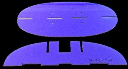
5 Before you start construction find all the acrylic parts and peel off the sticky protective plastic from both sides. 5


6 Make sure these two holes are top left and the base plate is orientated as shown here. We re off. This step is a nice easy one sticking on my feet! 6


7 7


")

8 spanner nut 10mm bolt (check using the part finder to avoid using the 12mm bolts here) Take care not to over tighten the nuts here folks. 8


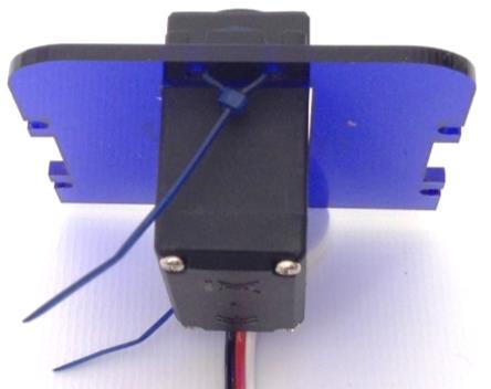
9 servo this way around not like this Curved edge to the front This servo will make Ohbot s head turn 9


10 Long cable ties 10


11 10mm bolt nut Curved edge to front There are some holes in the flat base plate. They should be at the back with the curved edge of the servo plate to the front. 11

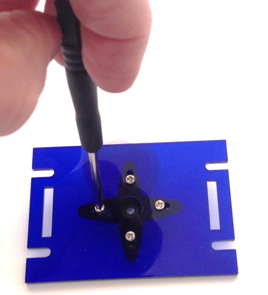
12 small servo screw 12


13 10mm bolt nut The black servo cross arm should be on the underside 13


14 short cable ties 14

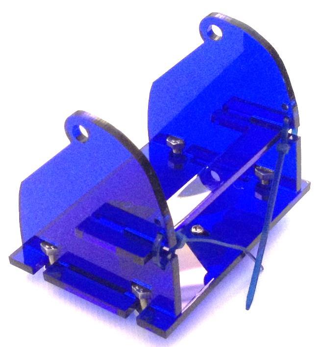
15 Push down gently This piece goes at the back Curved side to the front The next few steps will set up the head turn servo. 15


 front front")
16 1. Gently turn the neck piece clockwise as far as it will go 2. Lift off the neck piece 3. Orient the neck piece in the position shown, then push it back onto the servo front Curved edge to the front 4. Screw the neck piece onto the servo (shown here from behind) front front Large servo screw. It s in the bag with the large servo 16

17 spacer This is a pivot so Ohbot s head can tilt up and down 17

18 short cable ties Leave the cable ties loose so that the jaw can move freely easily Nice, now Ohbot s got a lower jaw. 18


19 Lift lower jaw Attach pad to the underside to secure the lip. Smile! 19


20 You will need: servo goes this way round not this way You re making Ohbot s right cheek! This servo moves its eyes up and down. 20

21 You will need: small servo screw 21


22 servo goes this way round not this way Now you re making Ohbot s left cheek! This servo will tilt its head up and down. 22


23 You will need: small servo screw 23


24 Orient this so the slot is on the left and these holes are on the right This is Ohbot s top lip. The servo moves the bottom lip up and down. Servo drive shaft on left wire down 24


25 long cable ties 25

26 Rest the top lip on the lower jaw 26


27 White cylinder should point in Ohbot s left cheek 10mm bolt nut Nut and bolt fasten the cheek to the upper jaw 27


28 Locate the end of the aluminium shaft in hole in cheek White cylinder should point in Ohbot s right cheek 10mm bolt nut Nut and bolt fasten the cheek to the upper jaw 28

29 grommet Push a grommet onto each end of the aluminium shaft 29


30 The white servo shaft should be on the side nearest the notches You ve got this far, great work! This is Ohbot s eye box. This servo will move its eyes left and right. 30

31 small servo screw 31


32 1. Fasten the sides using cable ties through the holes. Make sure that the buckle is on the inside of the eye box. short cable tie


33 1. Turn the eye box so that the curved side is down and the notches towards you 2. Place the servo so that the wire exits towards you and the white servo shaft points right 33

34 long cable tie 34


35 two holes eyelid one hole 12mm bolts plastic washers eyelid servo the two hole end of the eyelid should go on the right so that the eyelid servo arm can connect 35


36 locking nut Tighten the nuts just enough to lock but still allow the eye box to tilt freely 36


37 top underneath It might help to use a pair of pliers to straighten the wires first. 37


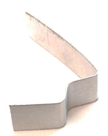
38 Do feel free to make your own nose and accessories 38


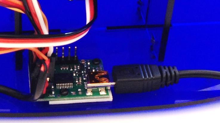
39 This board allows the computer to control Ohbot s servos. It can also be used to input data from sensors. 39

40 Ohbot s back Orient the circuit board with the Mini USB socket to the right 40


41 Brown or black on this side Yellow or white on this side 1. Find the plug for the servo marked 1 on the photo. Plug it into the board in the position shown. Make sure the yellow/white wire is to the right and the brown/black is to the left Do the same for the servo marked two, plugging it into the next position forward. Continue this until you have plugged all six servos into the board


42 1. Find this pair of pins Black on this side Red on this side Take care to get the power wires the right way around, or the servos will be damaged. 2. connect the power supply socket like this 42

43 Long cable tie 43

44 44

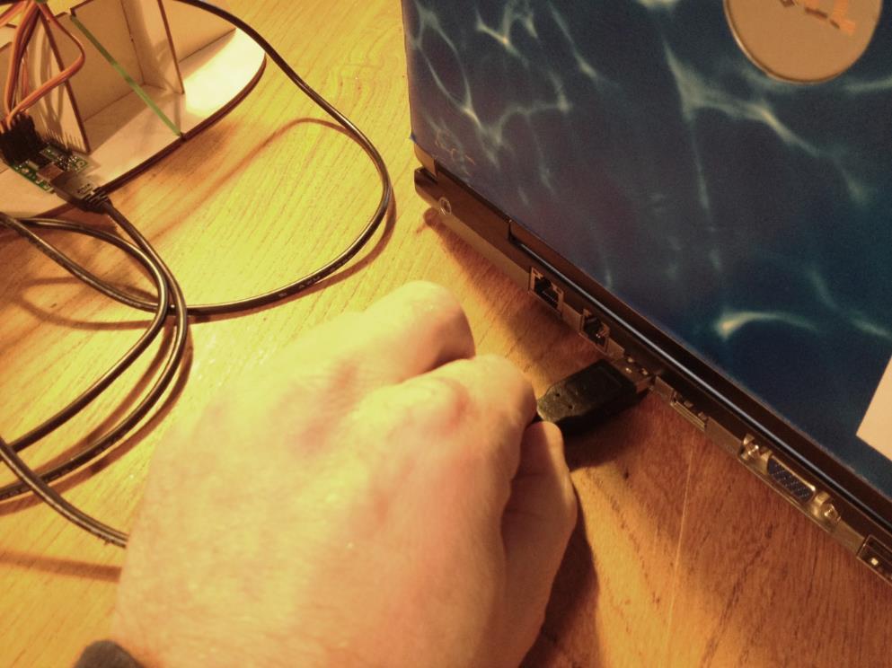
45 Install Ohbot Software Go to 45

46 46


47 1. Run the Ohbot software 2. On the Settings menu click on Motors Enter the password- Einstein to unlock the settings dashboard 4. Without the servo arms attached check that the corresponding servo moves as you drag the slider


48 Set up mouth open (servo 2 ) 1. Adjust the MouthOpen slider until Norm reads 0.0 Ensure there is a tick in the Reverse checkbox Warning! We recommend that you don t screw the arm on. The screw often damages the servo. 2. Use pliers to attach the arm onto the servo so that the mouth is closed with the arm pointing slightly forward 48


49 Set up eye turn (servo 4 ) 1. Adjust the slider until Norm reads 5.0 Warning! We recommend that you don t screw the arm on. The screw often damages the servo. 2. Attach the servo arm so the eyes are looking straight forward 49


50 Set up lid blink (servo 3 ) pliers 1. Adjust the LidBlink slider until Norm reads 10 Warning! We recommend that you don t screw the arm on. The screw often damages the servo. 2. Turn the eye box so that the eyes are pointing straight down. Bend the end of the eyelid in slightly. Put the servo wire through the hole at the bottom of the eye box. Hook the end through the hole. You may need to bend over the end of the wire and push back the end of the eyelids 3. Pull wire down to open the eyelids as far as they will go. Use pliers to attach the arm onto the servo in this position This bit is tough. If you can think of a way of making it easier let us know. 50


51 Set up head nod (servo 3 ) 1. Adjust the HeadNod slider until Norm reads 5.0. Ensure there is a tick in the Reverse checkbox. Warning! We recommend that you don t screw the arm on. The screw often damages the servo. 2. Thread one end of the servo wire through the hole in the neck first then attach the arm. Finally push the arm onto the servo so that the head is level, not tilted up or down. 51


52 Set up eye tilt (servo 1 ) 1. Adjust the EyeTilt slider until Norm reads 5.0 Warning! We recommend that you don t screw the arm on. The screw often damages the servo. 2. Thread the S shaped end of the servo wire into the hole at the front corner of the eye box 3. Thread the other end of the servo wire onto the servo arm. Push the servo arm onto the servo in a position that makes the eye box horizontal. 52
53 Hooray, you ve made your Ohbot! Now let the programming begin 53
Making Instructions Version 2.1 for Raspberry Pi
 Making Instructions Version 2.1 for Raspberry Pi Ohbot Ltd. 2017 About Ohbot has seven motors. Each connects to the Ohbrain circuit board and this connects to a computer using a cable. Ohbot software allows
EPPA2-KIT DUAL MONITOR ARM CONVERSION
 EPPA2-KIT DUAL MONITOR ARM CONVERSION EPPA2-KIT Rev A 10/17 Model EPPA2-KIT-XXX ASSEMBLY AND ADJUSTMENT EPPA2-KIT PARTS AND TOOLS PLEASE REVIEW these instructions before beginning the assembly and adjustment
Bunk Pod Front Entry Assembly Instructions
 Bunk Pod Front Entry Assembly Instructions www.podtime.co.uk enquiries@podtime.co.uk Working House Ltd How to assemble your pod This step by step guide will show how to assemble your pod(s) on site. It
ASSEMBLY AND ADJUSTMENT
 EPPA MONITOR ARM EPPA Rev A 10/17 Model EPPA-XXX ASSEMBLY AND ADJUSTMENT EPPA MONITOR ARM PARTS AND TOOLS PLEASE REVIEW these instructions before beginning the assembly and adjustment procedures. Check
WARNING: Prior to installation, turn the power off to the vending machine and unplug it from its power source. Also, make sure to level the machine.
 Installation of Gum and Mint Tray for National 147, 157, 167 Important Note: Please read all instructions thoroughly before continuing with installation of kit. If you are having problems installing the
The Mind Project s Iris 1 Robotic Arm. Assembly instructions Step 1
 The Mind Project s Iris 1 Robotic Arm Assembly instructions Step 1 Packing list Below you will find pictures and descriptions of each part. It may be helpful to take each piece out of the bag and place
ABM International, Inc.
 ABM International, Inc. Lightning Stitch required 1 1.0: Parts List head and motor assembly (Qty. 1) Reel stand (Qty. 1) Needle bar frame clamp (Qty. 1) Motor drive (Qty. 1) 2 Cable harness with bracket
INSTALLING YOUR NEW SPRING LIFT ARM KIT
 INSTALLING YOUR NEW SPRING LIFT ARM KIT 1. Measure the distance that the roof is to be raised. [If your lift system is completely non-functional, you will need to calculate or estimate this distance as
Patton Robotics ESRA II Expressive System for Robotic Animation
 Patton Robotics ESRA II Expressive System for Robotic Animation Assembly and Operation Instructions Version 1.0 Patton Robotics, LLC. 61 Hagan Drive New Hope, PA 18938 Copyright 2015 Patton Robotics, LLC.
ABM International, Inc. Navigator Assembly Manual
 ABM International, Inc. 1 1.0: Parts List Tablet (Qty. 1) Tablet mount (Qty. 1) NOTE: Mount may appear and operate different then image below Control Box (Qty. 1) Motor Power Supply (Qty. 1) 2 X-axis motor
BombiniBot Parts and Assembly
 BombiniBot Parts and Assembly Copyright 05 mindsensors.com / Parts Loose Parts: Part Quantity Tire Motor Mount 4-Wire Encoder Cable Encoder Wheel Velcro Strip Top Chasis Plate Bottom Chasis Plate Battery
Electric Skein Winder
 Electric Skein Winder Assembly and Use Package Contents 1 - Triangular Body (w/ motor) 1 - Cross Arm 1 - Left Foot (w/ yarn guide) 1 - Right Foot 1 - Adjustable Finger (w/ yarn clip) 3 - Adjustable Fingers
Tools Required: - Utility knife - 11/16 Deep socket - Ratchet - 11/16 Crescent wrench - Ratchet Extension - 1/4 socket - Electrical tape
 DESTROYER FRONT BUMPER INSTALL JL STEP 1 : GATHER YOUR TOOLS AND LAY OUT YOUR PARTS... Tools Required: - Utility knife - 11/16 Deep socket - Ratchet - 11/16 Crescent wrench - Ratchet Extension - 1/4 socket
meped v2 Assembly Manual
 meped v Assembly Manual The meped is an open source quadruped robot designed by Scott Pierce of Spierce Technologies, LLC. This design is released under the Creative Commons, By Attribution, Share Alike
Installation and Assembly - Universal Articulating Swivel Double-Arm for 42" - 60" Plasma Screens
 Installation and Assembly - Universal Articulating Swivel Double-Arm for 42" - 60" Plasma Screens Models: PLAV 70-UNL, PLAV 70-UNL-S PLAV 70-UNLP, PLAV 70-UNLP-S R This product is UL Listed. It must be
F i t t i n g t h e N e w L a n d i n g G e a r t o Y o u r S k y J i b V 1
 F i t t i n g t h e N e w L a n d i n g G e a r t o Y o u r S k y J i b V 1 1 P a r t s L i s t : S t a n d a r d L a n d i n g G e a r U p g r a d e Product Code Parts + Spares Product Code Parts + Spares
DO35 MAINTENANCE INSTRUCTIONS
 CUSTOMER INFORMATION SHEET NO. 038 DO35 MAINTENANCE INSTRUCTIONS (DO35 V3 LAUNCHED PRODUCTION JUNE 2017) Table of Contents 1.0 Replacing Spindle Bushes V3... 22 2.0 Replacing Locking Mechanism V3... 6
Installation and Assembly - Universal Articulating Swivel Double-Arm for 42" - 60" Plasma Screens
 Installation and Assembly - Universal Articulating Swivel Double-Arm for 42" - 60" Plasma Screens Models: PLAV 70-UNL, PLAV 70-UNL-S PLAV 70-UNLP, PLAV 70-UNLP-S R This product is UL Listed. It must be
Queen Wingback Bed King Wingback Bed
 Parts and Hardware List A. Side Rails with Attachment Hooks 2 pcs B. Foot Rail 1 pc C. Head Rail 1 pc D. Center Support Slat 1 pc E. Leg Supports 3 pcs F. Support Slats 4 pcs G. Flat Washers 8 pcs H. Lock
model tsa-sa48 Sliding Crosscut Table installation guide
 model tsa-sa48 Sliding Crosscut Table installation guide A Note About Color Variations Among Anodized Aluminum Components Congratulations on the purchase of this SawStop Sliding Crosscut Table. We at SawStop
Gardman Lean-to Greenhouse Assembly Instructions
 Page 1 Gardman Lean-to Greenhouse Assembly Instructions Our Help Line provides support and advice to customers of Summer Garden Buildings after ordering. For advice before you buy you can phone us free
STEP 1 : DESTROYER FRONT BUMPER INSTALL GATHER YOUR TOOLS AND LAY OUT YOUR PARTS... *shorty bumper to show hardware* Tools Required:
 DESTROYER FRONT BUMPER INSTALL JL STEP 1 : GATHER YOUR TOOLS AND LAY OUT YOUR PARTS... Tools Required: - Utility knife - 11/16 Deep socket - Ratchet - 11/16 Crescent wrench - Ratchet Extension - 1/4 socket
Replacing the Reciprocator on the SWF Compact Series Machine (601C and 1201C)
") Follow the instructions below to replace the reciprocator in the SWF Compact series machines. The tools required can be found in the tool kit that came with the machine. Preparation 1. First, place the
Follow the instructions below to replace the reciprocator in the SWF Compact series machines. The tools required can be found in the tool kit that came with the machine. Preparation 1. First, place the
GlideRite Retractable Cover System For Hot Spot Spas (SE & SLX only)
") List of Contents Quantity Description 12 #10 x 1 ½ Flat Head Phillips Screw (see pg. 2) 2 #10 x ½ Pan Head Phillips Screw (see pg. 2) 8 ¼ x 2 ½ Lag Bolt (see pg. 2) 7 ¼ 20 x 5 / 8 Hex Head Bolt (see pg.
List of Contents Quantity Description 12 #10 x 1 ½ Flat Head Phillips Screw (see pg. 2) 2 #10 x ½ Pan Head Phillips Screw (see pg. 2) 8 ¼ x 2 ½ Lag Bolt (see pg. 2) 7 ¼ 20 x 5 / 8 Hex Head Bolt (see pg.
Star Trac Turbo Trainer Assembly & Setup
 Star Trac Turbo Trainer Use the following procedures to unpack and assemble your Turbo Trainer manufactured by Star Trac. UNPACKING AND PARTS LIST Position the shipping carton so the Heavy End logo is
GlideRite Retractable Cover System For HotSpring & Tiger River Spas (except Classic & pre-2000 Landmark Spas)
") List of Contents Quantity Description 12 #10 x 1 ½ Flat Head Phillips Screw (see pg. 2) 2 #10 x ½ Pan Head Phillips Screw (see pg. 2) 8 ¼ x 2 ½ Lag Bolt (see pg. 2) 7 ¼ 20 x 5 / 8 Hex Head Bolt (see pg.
List of Contents Quantity Description 12 #10 x 1 ½ Flat Head Phillips Screw (see pg. 2) 2 #10 x ½ Pan Head Phillips Screw (see pg. 2) 8 ¼ x 2 ½ Lag Bolt (see pg. 2) 7 ¼ 20 x 5 / 8 Hex Head Bolt (see pg.
Installation Instruction
 Tools Needed for Assembly Stud finder (for wood stud wall) Pencil Mark Electric drill Wood Stud Wall Installation Step 1. Locate the Wood Studs Installation Instruction Drill bit (for wood stud wall) Masonry
Standard Operating Procedure
 RIT MULTIDISCIPLINARY SENIOR DESIGN 2010 Standard Operating Procedure Baja Water Propulsion Test Stand This SOP specifies how to assemble, use, troubleshoot, and disassemble the water propulsion system
Printrbot Simple (Model 1403) Rev F Printrboard
 Rev F Printrboard") Printrbot Simple (Model 1403) Rev F Printrboard Printrbot Simple is currently shipping with the Rev F Printrboard. Check which rev Printrboard your Simple kit includes and use the corresponding instructions.
Printrbot Simple (Model 1403) Rev F Printrboard Printrbot Simple is currently shipping with the Rev F Printrboard. Check which rev Printrboard your Simple kit includes and use the corresponding instructions.
C70 Window Roller Repair Taken from: Heres the problem:
 C70 Window Roller Repair Taken from: http://www.volvospeed.com/vs_forum/topic/115086-how-to-c70-window-rollers-permanent-fix/ Heres the problem: This happened to two separate window assemblys on my c70
Sliding Crosscut Table installation guide
 Sliding Crosscut Table installation guide model tsa-sa48 A Note About Color Variations Among Anodized Aluminum Components Congratulations on the purchase of this SawStop Sliding Crosscut Table. We at SawStop
WARNING!! DO NOT LIFT DOORS UP WHEN THE HOOD IS OPEN. THE DOORS WILL HIT THE HOOD!
 WARNING!! DO NOT LIFT DOORS UP WHEN THE HOOD IS OPEN. THE DOORS WILL HIT THE HOOD! THIS KIT INCLUDES: 4 M8-1.25X30MM BOLTS WITH WASHERS 12 M8-1.25X40MM BOLTS WITH WASHERS 2 SHOULDER BOLTS WITH RIGHT AND
INVENT3D Printer Kit Disassembly Instructions
 INVENT3D Printer Kit Disassembly Instructions Version 6 AST2 10/26/16 1 I. General Disassembly Instructions Use the case layer drawings to ensure that components are stored in the appropriate location
RPS. XR Front Drive Updates CORPORATION
 FACTORY CAT 1. To start a replacement of the XR Front Wheel Drive, make sure the machine is on level ground with the rear wheels chocked and always disconnect the batteries. 2. Locate the Positive and
The Mind Project s Iris 1 Robotic Arm. Packing List Assembly instructions
 The Mind Project s Iris 1 Robotic Arm Packing List Assembly instructions Packing list Below you will find pictures and descriptions of each part. It may be helpful to take each piece out of the bag and
MS2 Straight Key Kit Assembly Manual
 American Morse Equipment MS2 Straight Key Kit Assembly Manual Thank you for purchasing our MS2 Miniature Straight Key Kit! Please take a few minutes to look over these instructions before starting assembly.
N. 15th Street, Middlesboro, KY FLIP TARP DUMP BODY INSTALLATION INSTRUCTIONS
 1-800-248-7717 1002 N. 15th Street, Middlesboro, KY 40965 FLIP TARP DUMP BODY INSTALLATION INSTRUCTIONS Congratulations on your purchase of a Mountain Flip Tarp Dump Body tarping system. With tarping systems
INSTRUCTION BOOKLET #34. For Wallbed models: KING SIZE SIERRA WITH STORAGE HEADBOARD
 For Wallbed models: KING SIZE SIERRA WITH STORAGE HEADBOARD INSTRUCTION BOOKLET #34 WARNING! ALL MURPHY/WALLBED SYSTEMS CONTAIN STORED ENERGY. FAILURE TO USE AND FOLLOW THESE INSTRUCTIONS DURING THE INSTALLATION
TITAN2-EDGE Public Access Computer Station Dual Track
 TITAN2-EDGE Public Access Computer Station Dual Track TITAN2-EDGE Rev A 6/17 Model TITAN2-EDGE ASSEMBLY AND ADJUSTMENT TITAN2-EDGE PARTS AND TOOLS PLEASE REVIEW these instructions before beginning the
OpenROV. Guide 3 - Electronics. We will now move to the assembly of the electronics that will control the ROV. Written By: OpenROV
 OpenROV Guide 3 - Electronics We will now move to the assembly of the electronics that will control the ROV. Written By: OpenROV 2017 openrov.dozuki.com Page 1 of 33 INTRODUCTION We will introduce soldering
Installing the 3 Indexer: PRS Standard Tools
 888-680-4466 ShopBotTools.com Installing the 3 Indexer: PRS Standard Tools Copyright 2016 ShopBot Tools, Inc. page 1 Copyright 2016 ShopBot Tools, Inc. page 2 Table of Contents Route Cable into Box...5
3. X-axis assembly. 3. X-axis assembly. Written By: Jakub Dolezal manual.prusa3d.com/ Page 1 of 13
 3. X-axis assembly Written By: Jakub Dolezal 2018 manual.prusa3d.com/ Page 1 of 13 Step 1 Tools necessary for this chapter Needle-nose pliers for zip tie trimming. 2.5mm Allen key for M3 screws 2mm Allen
Sole Fitness E95 Elliptical Trainer TurnKey Delivery and Setup Training
 Sole Fitness E95 Elliptical Trainer TurnKey Delivery and Setup Training Delivery Requirements Ground delivery Inside delivery to customer-specified location Unpack and assemble machine, and remove packing
TOOLS REQUIRED FOR INSTALLATION: AIR RACHET, GRINDER AND CUTTER.
 THIS KIT INCLUDES: 16 M8-1.25X30MM BOLTS WITH WASHERS 2 SHOCKS 565 PSI RIGHT AND LEFT HINGE ASSEMBLY 2 SHOULDER BOLTS 2 PINS TOOLS REQUIRED FOR INSTALLATION: AIR RACHET, GRINDER AND CUTTER. 7/23, 10MM,
Please read BOTH these Installation Instructions and the General Instructions before attempting to install or operate this equipment.
 Please read BOTH these and the General Instructions before attempting to install or operate this equipment. 1. Blue Ox towing products and accessories are intended to be installed by Blue Ox Dealers who
Medium HoneyBadger Chase Rack Installation Instructions
 PREPARATION Medium HoneyBadger Chase Rack Installation Instructions 1. Disconnect the negative terminal on the battery. Park the vehicle on level ground and set the emergency brake. 2. We recommend reading
Hatch Whiteboard: Portable Stand Installation Instructions
 Hatch Whiteboard: Portable Stand Installation Instructions Remove Projector Wall Plate 1. Open the wall mount for the projector. 2. Remove the shipping screw from the front center of the mount arm. 1 P
MAIN PARTS
 MAIN PARTS 7 8 9 10 11 12 13 1 2 3 17 4 5 6 01 02 03 04 05 12 23 34 45 56 13 24 35 46 57 14 25 36 47 58 15 16 26 27 37 38 48 49 59 60 06 07 08 09 10 17 18 28 29 39 40 50 51 61 62 19 30 41 52 63 20 21 31
MM540 Installation Instructions IMPORTANT SAFETY INSTRUCTIONS - SAVE THESE INSTRUCTIONS
 MM50 Installation Instructions IMPORTANT SAFETY INSTRUCTIONS - SAVE THESE INSTRUCTIONS Please read this entire manual before you begin. Do not unpack any contents until you verify all requirements on PAGE.
Installation Instructions for FC2 & FC15 Forward Controls for the Super Magna
 Installation Instructions for FC2 & FC15 Forward Controls for the Super Magna It is highly recommended that you use a thread lock compound such as Loctite brand on all threads to keep them from vibrating
INSTALLATION INSTRUCTIONS HEAVY DUTY TILT WALL MOUNT Model: PPH-2000
 INSTALLATION INSTRUCTIONS HEAVY DUTY TILT WALL MOUNT Model: PPH-2000 Specifications: Accomodates Akira and Orion 84" displays without interface bracket; accomodates other large flat panel displays with
Part 7 Assembling the X axis
 Part 7 Assembling the X axis 1 2 The X axis is a key part of the printer, it carries the extruder on a carriage that moves the extruder laterally in the X axis. The x axis itself is moved vertically on
INSTALLATION GUIDE 8IWBM-EL. phone: (02) fax: (02)
 fax: (02)") INSTALLATION GUIDE 8IWBM-EL www.gilkon.com.au email: sales@gilkon.com.au phone: (02) 99140900 fax: (02) 99140901 CONTENTS 1. DISCLAIMER Page 2 2. WARNINGS & SAFETY INSTRUCTIONS Page 3 3. PACKAGE CONTENTS
INSTALLATION GUIDE 8IWBM-EL www.gilkon.com.au email: sales@gilkon.com.au phone: (02) 99140900 fax: (02) 99140901 CONTENTS 1. DISCLAIMER Page 2 2. WARNINGS & SAFETY INSTRUCTIONS Page 3 3. PACKAGE CONTENTS
Customer Notice: Congratulations again on your SawStop purchase, and thank you! -SawStop Tualatin, OR
 Customer Notice: Congratulations on the purchase of this Sliding Crosscut Attachment. As the owner of a SawStop saw, you are familiar with our high standards for quality, fit and finish. Different from
LifeGear G1 /HOME GYM ITEM NO.: 63100
 LifeGear G1 /HOME GYM ITEM NO.: 63100 OWNER S MANUAL IMPORTANT: Read all instructions carefully before using this product. Retain this owner s manual for future reference. The specifications of this product
STOP! READ THIS FIRST
 STOP! READ THIS FIRST Page 1 of 37 Getting Started With Your Pantograms GS1501 Embroidery Machine (the quick guide) Thank you for choosing Pantograms for your embroidery system provider. We encourage you
Hollywood Swing Away 2 and 4 Bike Racks Assembly and Installation Guide
 Hollywood Swing Away 2 and 4 Bike Racks Assembly and Installation Guide Tools Required: two adjustable wrenches, pliers, ¾ socket wrench recommended Note: please do assembly near your vehicle as you Can
WOLF PUP LOOM TM & WOLF PUP LT LOOM TM
 WOLF PUP LOOM TM & WOLF PUP LT LOOM TM Assembly Instructions FL3000 FL3006 FL3009 WOLF PUP WOLF PUP LT Find out more at schachtspindle.com Schacht Spindle Company 6101 Ben Place Boulder, CO 80301 p. 303.442.3212
OPERATIONAL MANUAL V1.0. Removing/Replacing Blades
 OPERATIONAL MANUAL V1.0 BLUEROCK WS-212 Wire Stripper Removing/Replacing Blades CAUTION!! IMPORTANT!! DANGER!! WARNING!! DISCONNECT MACHINE FROM POWER BEFORE PROCEEDING!! Estimated Completion Time: 90
Greenhouse Assembly Instructions
 Greenhouse Assembly Instructions Our Help Line provides support and advice to customers of Summer Garden Buildings after ordering. For advice before you buy you can phone us free 7 days a week on 0800
MM340 Installation Instructions IMPORTANT SAFETY INSTRUCTIONS - SAVE THESE INSTRUCTIONS
 MM30 Installation Instructions IMPORTANT SAFETY INSTRUCTIONS - SAVE THESE INSTRUCTIONS Please read this entire manual before you begin. Do not unpack any contents until you verify all requirements on PAGE.
BABY WOLF LOOM. Assembly Instructions for Knocked-Down Looms
 BABY WOLF LOOM Assembly Instructions for Knocked-Down Looms BEFORE YOU BEGIN Please read through the directions before beginning to assemble your loom. Unpack the loom parts carefully. Do not throw away
EDGE2 DUAL MONITOR ARM
 EDGE2 DUAL MONITOR ARM EDGE2 Rev A 2/17 Model EDGE2-SLV Model EDGE2-BLK Model EDGE2-WHT ASSEMBLY AND ADJUSTMENT EDGE2 DUAL MONITOR ARM PARTS AND TOOLS PLEASE REVIEW these instructions before beginning
Step 1: Gather your parts!
 Step 1: Gather your parts! Show All Items The #mearm was designed with economy in mind. It is understood that laser cutters aren't the most common tools but there are more of them out there now than
SIGNATURE FRONT BUMPER INSTALL
 SIGNATURE FRONT BUMPER INSTALL JL **PLEASE READ THROUGH THE INSTRUCTIONS BEFORE BEGINNING ANY PART OF THE INSTALLATION PROCESS** 1. You can now remove the trim strip (2 vertical clips, 4 horizontal, 2
Obtained from Omarshauntedtrail.com
 DaveintheGrave's Halloween Props Animated Crawling Skeleton Build a life-size skeleton torso that realistically crawls across the lawn one arm at a time. 1. Motor Base and Linkage Assembly BASE - I used
Heavy Duty Ceiling Tilt Mount Installation Manual
 HD-CTM-5580 Heavy Duty Ceiling Tilt Mount Installation Manual *This Installation requires a minimum of two people. For your safety: Read the complete instruction manual before starting an installation
MOTOR REPLACEMENT : STEP BY STEP.
 (D) REPLACEMENT : STEP BY STEP. (V) Adjustment screw (Allen key 3/16 ) (E) (U) (I) Tightening screw (Allen key 5/32 ) Blocking screw (H) (Allen key 5/32 ) (G) (Y) (T) (ZZ) (Z) (K) (X) (L) (S) (W) (R) (Q)
Equilibrium. Conference Table. Installation Instruction. Revision B 11/07/16
 Equilibrium Conference Table Installation Instruction Revision B 11/07/16 Equilibrium End User Agreement Enwork Equilibrium table bases must be installed directly onto a four inch minimum thickness concrete
THIS KIT INCLUDES: 8 M8-1.25X40MM BOLTS WITH WASHERS 8 M8-1.25X30MM BOLTS WITH WASHERS RIGHT AND LEFT HINGE
 Sal es@lambodoorscanada. com 2407A Kal adarave,ottawa,on K1V 8B9 THIS KIT INCLUDES: 8 M8-1.25X40MM BOLTS WITH WASHERS 8 M8-1.25X30MM BOLTS WITH WASHERS RIGHT AND LEFT HINGE 2 SHOCKS 565 PSI 2 SHOULDER
BEAST THE. Tube and Pipe Notcher Operating Instructions. Notches In Bends Straight Notches. Angled Notches. Offset Notches
 Copyright (c) 2007 J D SQUARED INC. www.jd2.com THE BEAST Tube and Pipe Notcher Operating Instructions Notches In Bends Straight Notches Angled Notches PATENT PENDING Offset Notches Assembly After unpacking
L.L.Bean. Farmhouse Futon
 L.L.Bean Farmhouse Futon Thank you for purchasing our Farmhouse Futon. Assembly of this product requires a Phillips Head Screwdriver and Flat Head Screwdriver. We have found it helpful to have a second
FACTORY CAT TOMCAT CORPORATION
 FACTORY CAT RPS TOMCAT CORPORATION Artificial Turf and Carpet Sweeping Install Kit #349-641 & #349-642 1. Detach batteries so that there is no power running through the machine before starting. 2. Start
CORVETTE CORVETTE REV: Made in USA U.S. PATENT #6,808,223; #6,845,547; #7,140,075; #7,059,655 and other patents pending.
 CORVETTE 2005-2006 CORVETTE 2005-2007 REV: 7-2-07 Made in USA U.S. PATENT #6,808,223; #6,845,547; #7,140,075; #7,059,655 and other patents pending. Page 1 of 12 CORVETTE C6 2005-2007 THIS KIT INCLUDES:
The Useless Machine. DIY Soldering Edition. Instruction Guide v0004
 The Useless Machine DIY Soldering Edition Instruction Guide v0004 TM For the best outcome, follow each step in order. We recommend reading this guide entirely before you get started. Tools required: Soldering
ASSEMBLY AND ADJUSTMENT
 EDGE MONITOR ARM EDGE Rev A 2/17 Model EDGE-SLV Model EDGE-BLK Model EDGE-WHT ASSEMBLY AND ADJUSTMENT EDGE MONITOR ARM PARTS AND TOOLS PLEASE REVIEW these instructions before beginning the assembly and
INSTALLATION: D1-NOTCH DRYWALL TRIM FLANGE
 T F W 604.549.979 604.549.9555 fluxwerx.com INSTALLATION: D1-NOTCH DRYWALL TRIM FLANGE fixture housing endcap kit optic kit join kit notch 2 cross section notch 4 cross section 4 4" 4-11/2" 4 /8 (111)
Tools: Sharpie, Square, Vise, Hack saw, Ruler, Punch, Hammer, File. 2. Cut the stock Place stock in vise and cut with hack saw
 Purpose: MAKE CATAPULT ARM Step 1 Tools: Sharpie, Square, Vise, Hack saw, Ruler, Punch, Hammer, File Materials: Flat aluminum ½ inch stock (see picture below) Gloves required 1. Pick up the aluminum ½
Horizontal Cable Systems
 ALUMINUM RAILING INSTALLATION INSTRUCTIONS v2012 orizontal Cable Systems 1) Check Contents Of Packages: Verify that all parts have arrived and that they match the packing list. 1A) Coastal applications:
Hardware and Components:
 Hardware and Components: (A) 5/16 x 2 Hex Bolt (B) 5/16 x 2-1/4 Hex Bolt (C) 5/16 x 2-1/2 Hex Bolt (D) 4X 5/16 x 3/4 Hex Bolt (E) 4X 5/16 x 1-1/4 Hex Bolt (F) 11X 5/16 Flat Washer (G) 12X 5/16 Nylock Nut
LCD LIFT Flat Panel Display System Installation Manual. Table of Contents
 LCD LIFT Flat Panel Display System Installation Manual Table of Contents Page Installation Overview... 2 Trim Ring Installation... 3 LCD Lift Installation....4 Actuator Switch Installation.5 Top Plate
User Instructions Multiline Otter Scoreboard Caddy Assembly
 List of parts: User Instructions Multiline Otter Scoreboard Caddy Assembly Single Caddy Double Caddy 1 1 Base assembly with attached wheels 2 4 1 1 2 4 4 8 10 20 12 Uprights (60 or 74 aluminum extrusion)
RIPPER PEDAL. Bearing / Axle Replacement. ( Disassembly )
") RIPPER PEDAL Bearing / Axle Replacement ( Disassembly ) 1 1. Use good quality tools to avoid stripping screw sockets. 2. When servicing your pedals, work on one side at a time to prevent parts from mixing
RIPPER PEDAL Bearing / Axle Replacement ( Disassembly ) 1 1. Use good quality tools to avoid stripping screw sockets. 2. When servicing your pedals, work on one side at a time to prevent parts from mixing
Assembly and installation help
 Assembly and installation help A supplement to the directions The Purpose of this tutorial is to expand (not replace) upon the directions that come with the system and to help provide shortcuts, the first
INSTRUCTION BOOKLET #C20
 INSTRUCTION BOOKLET #C0 WARNING! ALL MURPHY/WALLBED SYSTEMS CONTAIN STORED ENERGY. FAILURE TO USE AND FOLLOW THESE INSTRUCTIONS DURING THE INSTALLATION PROCESS COULD RESULT IN SEVERE PERSONAL INJURY TO
Arc Trainer Main Frame Assembly
 Arc Trainer Main Frame Assembly Kit No. 610AK019-4 Kit No. 630AK019-4 NOTE: This instruction sheet describes how to replace the main frame assembly in the Arc Trainer 610A. Tools Required 3/16 Allen wrench
Rocketry Challenge - Technical Document I
 Rocketry Challenge - Technical Document I This document includes a list of what is inside the kit with pictures for hard to decipher parts and a simple step-by-step process of how to assemble and launch
OTHER TOOLS MAY BE NEEDED DEPENDING ON YOUR VEHICLE.
 THIS KIT INCLUDES: 16 M8-1.25X40MM BOLTS WITH WASHERS 2 SHOCKS 720 PSI RIGHT AND LEFT HINGE ASSEMBLY 2 SHOULDER BOLTS 2 PINS TOOLS REQUIRED FOR INSTALLATION: AIR RACHET, GRINDER AND CUTTER. 10MM, 11MM,
Assembly Instructions 10 X 10 Aluminum Roof Support
 Assembly Instructions 10 X 10 Aluminum Roof Support Aluminum Roof Support Bolt Package 16-5/16 X 2 ¼ SS Bolt 24-5/16 X 1 SS Bolt 40-5/16 SS Nylon Lock Nuts 16-5/16 SS Flat Washers 28-4 ½ Wood Screws 36-1
OPERATOR'S MANUAL 46" SNOW BLADE. Model Numbers OEM IMPORTANT: READ SAFETY RULES AND INSTRUCTIONS CAREFULLY
 OPERATOR'S MANUAL 46" SNOW BLADE Model Numbers 190-833-OEM IMPORTANT: READ SAFETY RULES AND INSTRUCTIONS CAREFULLY MTD PRODUCTS INC. P.O. BOX 368022 CLEVELAND, OHIO 44136-9722 PRINTED IN U.S.A. FORM NO.
Installation Instructions
 Articulating Dual Monitor Mount Stand Installation Instructions UNPACKING Carefully open the carton, remove contents, and place them on a protected surface to avoid damage. Check the parts and the Supplied
Special Z-Axis Ballscrew Replacement
 To replace Z-axis ballscrew without removing X-axis components When rebuilding an OmniTurn slide, all the precision components are replaced. The tooling plate and saddle are removed to gain access to the
Installation and Assembly: In-wall Mount for 32" to 71" Flat Panel Screens
 Installation and Assembly: In-wall Mount for 32" to 71" Flat Panel Screens Model# IM760P, IM760P-S IM760PU, IM760PU-S Screen size range 32" to 71" (81 to 180 cm) 32" to 60" (81 to 152 cm) IM760P IM760P-S
v1.0 ASSEMBLY GUIDE Mia Wide Bookcase
 v1.0 ASSEMBLY GUIDE Mia Wide Bookcase Components Upon unpacking your bookcase from it s delivery box, you should have the pieces shown. Follow the steps on the next pages to assemble your new bookcase.
Removing and Replacing the Y-truck
 Service Documentation Removing and Replacing the Y-truck To remove and replace the Y-truck you will need the following tools: 4mm Allen wrench 12mm stamped flat wrench #2 Phillips screwdriver (magnetic
INSTALLATION INSTRUCTIONS
 INSTALLATION INSTRUCTIONS SPORTSMAN WINCH MOUNT GRILLE GUARD APPLICATION: 2016-2018 Toyota Tacoma PART NUMBER: 40-93885, 45-93880, 46-23885 ITEM QUANTITY DESCRIPTION TOOLS NEEDED 1 1 WINCH TRAY 15MM SOCKET
ESRA III. Expressive System for Robotic Animation
 ESRA III Expressive System for Robotic Animation 1 ESRA III Kit Contents 1 Hitec Servos 8 Upper Eye Support 2 Dagu (New as of 7/12) 9 Lower Eye Support 3 Eye Balls 10 Main Support 4 Flat Servo Plate 11
Lumber Smith. Assembly Manual. If you are having problems assembling the saw and need assistance, please contact us at:
 Lumber Smith Assembly Manual If you are having problems assembling the saw and need assistance, please contact us at: 804-577-7398 info@lumbersmith.com 1 Step 1 Safety Carefully read the Owners Manual.
M2 Assembly. M2 Sub-Assemblies mm Belt Sub-Assembly mm Belt Sub-Assembly Spider Sub-Assembly... 4
 M2 Assembly Table of Contents M2 Sub-Assemblies... 3 630mm Belt Sub-Assembly... 3 702mm Belt Sub-Assembly... 3 Spider Sub-Assembly... 4 Idler Bolt Sub-Assembly... 8 Y Motor Sub-Assembly... 9 X Motor Sub-Assembly...
American Morse Equipment
 American Morse Equipment Thank you for purchasing an American Morse Porta Paddle-II Kit. We redesigned the original Porta Paddle for ease of assembly & provide all parts finished and ready for assembly,