Making Instructions Version 2.1 for Raspberry Pi
|
|
|
- Douglas Bond
- 5 years ago
- Views:
Transcription


1 Making Instructions Version 2.1 for Raspberry Pi Ohbot Ltd. 2017

2 About Ohbot has seven motors. Each connects to the Ohbrain circuit board and this connects to a computer using a cable. Ohbot software allows humans to create programs to make Ohbot s motors move. Eyes turn motor Eyes tilt motor Lid blink motor Head tilt motor Bottom lip move motor Head turn motor Top lip move motor Ohbrain circuit board 2

3 Kit Parts A B D E C x3 3


4 You will need The Ohbot V2.1 kit scissors Long nose pliers The Ohbot Part Finder sheet A Raspberry Pi computer An hour or possibly a little more A bowl to hold small parts until they are needed 4

5 Instructions Each page is a step in constructing Ohbot The parts needed are shown on the top left of each page If you need tools it will show this too The main picture or pictures show how to assemble Look out for my tips too! 5


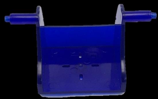
6 Feet underside of base Nice work! I don t want to brag, but Ohbots do have two more feet than you do! 6


7 Neck turn motor 1. Place the base so that the Ohbot sticker is facing toward you Ohbot sticker 2. Thread the motor s cable through the big hole on the top of the base then put the motor in so that the writing on the label is the right way up. This motor allows me to shake my head. No really, it does! 7
. 2.")

8 Fixing the neck turn motor back 1. Attach the motor to the base using the cable tie (shown in green). 2. Chop off the end of the cable tie front Don t chop your finger off while cutting the ties. Just saying! 3. Attach the motor to the base using the cable tie 4. Chop off the end of the cable tie 8


9 Attaching the neck Push down 9


10 Setting up the neck turn motor 1. Make sure the base is facing you with the Ohbot sticker to the front. Gently turn the neck piece clockwise as far as it will go 2. Lift off the neck piece 3. Orient the neck piece in the position shown, then push it back onto the motor Ohbot sticker front 4. Screw the neck piece onto the motor 10


11 Attaching lip motors Curved side of jaw Bottom lip motor Top lip motor Flat side of jaw Make sure the wires come out of the motors on the curved side of the jaw and go underneath the bottom lip motor. Label the wires for the top and bottom lip to make them easier to identify later. 11


12 Fixing left cheek motor left cheek 1. Orient the motor with the cable coming out towards the top of the cheek. Thread the cable through the hole. 2. Push the motor through at an angle, starting with the end of the motor where the cable comes out 3. Clip the motor in place It s easy to muddle right and left cheeks later. Why not label this one Ohbot s lovely left cheek so you can find it later. top top 12


13 Fixing right cheek motor You will need: right cheek 1. Orient the motor this way round, with the wire coming out of the motor to the top of the cheek. 2. Clip in place This motor allows me to roll my eyes. I know it s not polite, but Ohbots only do what they are programmed to do top top top The wire should be at the top 13


14 Attach the left cheek to the jaw lugs 1. Locate the lugs of the jaw in the slots on the cheek 2. Fasten the screw left cheek slots 14


15 Locating the jaw and cheek on the neck 1. Locate the pin on the neck in the hole in the left cheek 2. Hold in place ready for the next step pin hole 15


16 Attaching the right cheek to the jaw 16


17 Fixing the cheeks to the neck 1. Use screw to fasten the right cheek to the neck 2. Do the same for the left cheek 17


18 Fixing the eye turn motor Place the motor so that the motor shaft is on the opposite side to the posts. posts clip clip motor shaft To clip the motor in use the motor to push the clips apart. Find the end of the motor where the wire comes out and push this through the hole first. If it is tricky try taking the sticker off the motor. 18

19 Fixing the lid blink motor underneath motor shaft Make sure the cables for both the eye turn motor and the lid blink motor come out on the same side. Eye turn motor cable Lid blink motor cable 19


20 Attaching the eyelids hole eyebox hole Thread the link through this hole before clipping in the eyelid link arm eyelids arm pin pin link 20


21 Attachng the eyeballs down up If you find one of Ohbot s eyes is looking up and the other one down turn one of the eyeballs up the other way. turn upside down level 21


22 Attaching eyebox to the cheeks hole hole 1. Put the pins for the eyebox into the holes shown on the cheeks 2. Use screws to attach each cheek to the eyebox. pin pin 22


23 Nose fitting 23


24 Connecting motor 4 to Ohbrain Find the socket 4 at the end of the wire for the motor marked On the Ohbrain board locate the set of pins marked D4. 3. Attach the socket to the pins marked D4. Make sure the brown wire is to the left (-) and the yellow wire is to the right (S) Brown on this side Yellow on this side 24


25 Connecting motors to Ohbrain Find the socket for each motor in turn and plug it into the matching D numbered pins on the Ohbrain circuit board. Motor 5 goes to D5, Motor 6 to D6, Motor 7 to D7, Motor 8 to D8, Motor 9 to D9 and Motor 10 to D Take care to ensure that all sockets are connected this way: 25

26 Fixing Ohbrain to the base Back of base C C C Don t do these up too tight, just tighten enough to stop the board being wobbly. 26
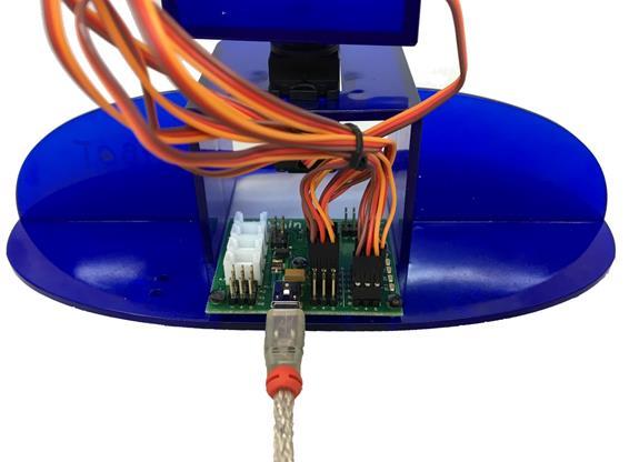

27 Connecting the cable to Ohbrain 27

28 Installing the Python library onto the Raspberry Pi If are new to Pi go to and follow the setup instructions Pi enthusiasts can visit the Ohbot GitHub site for more detail on installation and use of the Ohbot Python module 28
")
29 Connecting Ohbot to a Raspberry Pi Ohbot needs one USB plug connected to your Raspberry Pi and one connected to a 5V power supply rated 1amp or more which has a USB socket on it (not supplied) 29


 3.")


30 Setting up Motor 4 (makes Ohbot s head nod) Motor 4 1. Thread the link through the end hole of the motor arm 2. Create a reset program: from ohbot import ohbot ohbot.reset() 3. Hold Ohbot s head upright Motor arm Run the program end hole link end hole Not like this Yes! That s right 4. Thread the link through the hole on the side of the neck 5. Find Motor 4. Push the arm onto the motor so it holds Ohbot s head upright. 6. Fix the arm onto the motor using screw B hole push onto motor 30


31 Setting up Motor 64 (makes my eyes turn) Motor 6 1. Thread the link through the end hole of the motor arm 2. Create a reset program: from ohbot import ohbot ohbot.reset() 3. Find Motor 6. Push the motor arm on in the position shown in the photo. Put the ends of the link through the holes in the eyeballs. Motor arm Run the program link end hole end hole hole hole 4. Use pliers to bend the ends of the wires 6. Fix the arm onto the motor using screw B 31


32 Setting up Motor 74 (blinks my eyelids) Motor 7 2. Create a reset program: from ohbot import ohbot ohbot.reset() 2. Thread the link onto the end hole on the arm. Run the program end hole arm 3. Push the arm onto the servo so that it holds the eyelids wide open 4. Tilt the eyebox up fix the arm onto the motor using screw B 32


33 Setting up Motor 104 (tilts my eyes) Motor Thread the hook end of the link through the end hole of the motor arm 2. Create a reset program: from ohbot import ohbot ohbot.reset() 3. Thread the S shaped end of the link into the hole at the front corner of the eye box Run the program end hole go through the end hole hole arm s shaped end 5. Hold the eyebox so the upright on its front edge is flush with the cheek No Yippee 6. Find Motor 10. Push the arm onto the motor so it holds the eyebox horizontal. 6. Fix the arm onto the motor using screw B hook shaped end No push onto motor 33


34 Setting up Motor 84 (moves my top lip) Motor 8 2. Create a reset program: from ohbot import ohbot ohbot.reset() Run the program 2. Attach the lip onto the servo so that it is horizontal Not like this Like this or this Ohbot s lips are identical and either can be used for top or bottom 2. Create a program containing the command ohbot.reset() and run the program. 4. Use screw B to secure the lip in place 34


35 Setting up Motor 94 (moves my bottom lip) Motor 9 2. Create a reset program: from ohbot import ohbot ohbot.reset() Run the program 2. Push the the Bottom Lip onto the the servo so that it is horizontal beneath the top lip just like in the picture Ohbot s lips are identical and either can be used for top or bottom 2. Create a program containing the command ohbot.reset() and run the program. 4. Use screw B to secure the lip in place 35

36 Hooray! You ve assembled an Ohbot! This is just the start though. How your Ohbot behaves depends on on your imagination and programming. Happy inventing! 36
Ohbot. Eyes turn. servo. Eyelids open. servo. Head tilt. servo Eyes tilt. servo. Mouth open servo. Head turn servo
 Making Instructions Ohbot Ohbot has six servo motors. The servos allow each part of the face to be positioned precisely. Eyelids open servo Eyes tilt servo Eyes turn servo Head tilt servo Mouth open servo
Build your own. Stages 7-10: See Robi s head move for the first time
 Build your own Pack 03 Stages 7-10: See Robi s head move for the first time Build your own All rights reserved 2015 Published in the UK by De Agostini UK Ltd, Battersea Studios 2, 82 Silverthorne Road,
Open Air. Kit includes: Drawer Full Indicator board assembly, (2) retainers, and (4) screws. PREPARATION
 retainers, and (4) screws. PREPARATION") Open Air Installation Video You will need: 8-inch #2 Phillips screwdriver Needle-nose pliers DFI INSTALLATION GUIDE For installation videos, visit the Customer Service playlist at www.youtube.com/user/thelitterrobot
Open Air Installation Video You will need: 8-inch #2 Phillips screwdriver Needle-nose pliers DFI INSTALLATION GUIDE For installation videos, visit the Customer Service playlist at www.youtube.com/user/thelitterrobot
Replacing the Reciprocator on the SWF Compact Series Machine (601C and 1201C)
") Follow the instructions below to replace the reciprocator in the SWF Compact series machines. The tools required can be found in the tool kit that came with the machine. Preparation 1. First, place the
Follow the instructions below to replace the reciprocator in the SWF Compact series machines. The tools required can be found in the tool kit that came with the machine. Preparation 1. First, place the
WARNING: Prior to installation, turn the power off to the vending machine and unplug it from its power source. Also, make sure to level the machine.
 Installation of Gum and Mint Tray for National 147, 157, 167 Important Note: Please read all instructions thoroughly before continuing with installation of kit. If you are having problems installing the
Value Location Qty Potentiometers C1M Distortion 1 A10k Volume 1. Footswitch 3PDT SW1 1. Jacks 1/4 Mono 2 DC Power 1
 Distortion BUILD INSTRUCTIONS Thank you for your purchase of our Distortion+ kit! We have completely redesigned our entire line of kits to be the most user friendly, while still maintaining their same
Patton Robotics ESRA II Expressive System for Robotic Animation
 Patton Robotics ESRA II Expressive System for Robotic Animation Assembly and Operation Instructions Version 1.0 Patton Robotics, LLC. 61 Hagan Drive New Hope, PA 18938 Copyright 2015 Patton Robotics, LLC.
MS2 Straight Key Kit Assembly Manual
 American Morse Equipment MS2 Straight Key Kit Assembly Manual Thank you for purchasing our MS2 Miniature Straight Key Kit! Please take a few minutes to look over these instructions before starting assembly.
Value Location Qty Transistors 2N5485 Q1, Q2, 4 Q3, Q4 2N5087 Q5 1. Trim Pots 250k VTRIM 1. Potentiometers C500k Speed 1. Toggle Switch On/On Vibe 1
 P-90 BUILD INSTRUCTIONS Thank you for your purchase of our P-90 kit! We have completely redesigned our entire line of kits to be the most user friendly, while still maintaining their same great sound!
Roomba 500 Series Servicing and Repair Guide. Chapter 3: How to Open Up Roomba
 Roomba 500 Series Servicing and Repair Guide Chapter 3: How to Open Up Roomba 1 This repair guide explains how to perform general disassembly on the Roomba 500 series robot vacuum. It is suggested to consult
INSTALLATION GUIDE 8IWBM-EL. phone: (02) fax: (02)
 fax: (02)") INSTALLATION GUIDE 8IWBM-EL www.gilkon.com.au email: sales@gilkon.com.au phone: (02) 99140900 fax: (02) 99140901 CONTENTS 1. DISCLAIMER Page 2 2. WARNINGS & SAFETY INSTRUCTIONS Page 3 3. PACKAGE CONTENTS
INSTALLATION GUIDE 8IWBM-EL www.gilkon.com.au email: sales@gilkon.com.au phone: (02) 99140900 fax: (02) 99140901 CONTENTS 1. DISCLAIMER Page 2 2. WARNINGS & SAFETY INSTRUCTIONS Page 3 3. PACKAGE CONTENTS
Bunk Pod Front Entry Assembly Instructions
 Bunk Pod Front Entry Assembly Instructions www.podtime.co.uk enquiries@podtime.co.uk Working House Ltd How to assemble your pod This step by step guide will show how to assemble your pod(s) on site. It
Bend-Tech Dragon Assembly Manual
 p.1 Bend-Tech Dragon Assembly Manual IMPORTANT: Please read before unpacking. Place shipping container in a wide open area where you will have room to work and assemble this product. Shipping The Dragon
T-5 Floor Model SunLite Garden Assembly Instructions
 T-5 Floor Model SunLite Garden Assembly Instructions The Floor Model Light Garden can be used alone or as a base for our popular Tabletop Light Garden (sold separately). Assembly takes less than an hour
3. X-axis assembly. 3. X-axis assembly. Written By: Jakub Dolezal manual.prusa3d.com/ Page 1 of 13
 3. X-axis assembly Written By: Jakub Dolezal 2018 manual.prusa3d.com/ Page 1 of 13 Step 1 Tools necessary for this chapter Needle-nose pliers for zip tie trimming. 2.5mm Allen key for M3 screws 2mm Allen
LCD LIFT Flat Panel Display System Installation Manual. Table of Contents
 LCD LIFT Flat Panel Display System Installation Manual Table of Contents Page Installation Overview... 2 Trim Ring Installation... 3 LCD Lift Installation....4 Actuator Switch Installation.5 Top Plate
ABM International, Inc.
 ABM International, Inc. Lightning Stitch required 1 1.0: Parts List head and motor assembly (Qty. 1) Reel stand (Qty. 1) Needle bar frame clamp (Qty. 1) Motor drive (Qty. 1) 2 Cable harness with bracket
Installation and Assembly - Universal Articulating Swivel Double-Arm for 42" - 60" Plasma Screens
 Installation and Assembly - Universal Articulating Swivel Double-Arm for 42" - 60" Plasma Screens Models: PLAV 70-UNL, PLAV 70-UNL-S PLAV 70-UNLP, PLAV 70-UNLP-S R This product is UL Listed. It must be
LF Series Assembly Instructions
 LF Series Assembly Instructions 1998760 Revision A-10 Complete Series Master Packet 2010 Kimball International, Inc. T 800.482.1818 F 812.482.8300 Footprint Storage and Metal Filing Systems Assembly Instructions
Queen Wingback Bed King Wingback Bed
 Parts and Hardware List A. Side Rails with Attachment Hooks 2 pcs B. Foot Rail 1 pc C. Head Rail 1 pc D. Center Support Slat 1 pc E. Leg Supports 3 pcs F. Support Slats 4 pcs G. Flat Washers 8 pcs H. Lock
Build your own. Pack. Stages 19-22: Continue building Robi s left arm
 Build your own Pack 06 Stages 19-22: Continue building Robi s left arm Build your own All rights reserved 2015 Published in the UK by De Agostini UK Ltd, Battersea Studios 2, 82 Silverthorne Road, London
K1098 Priceless Salon Styling Chair
 K1098 Priceless Salon Styling Chair Keller International, LLC. 1-800-572-8772 1 Part # Part Name Picture Pieces 1 Armrests 1 left and 1 right 2 Backrest 1 3 Seat 1 4 Footrest 1 5 Pump Bail 1 6 G2 Pump
Written By: Brook Drumm
 Simple 1401 Assembly For kits produced between 1/15/14-6/1/14. This guide is for kits with the Fan Shroud. Instructions for metal and wood extruder (and bed) included below. Written By: Brook Drumm TOOLS:
Obtained from Omarshauntedtrail.com
 DaveintheGrave's Halloween Props Animated Crawling Skeleton Build a life-size skeleton torso that realistically crawls across the lawn one arm at a time. 1. Motor Base and Linkage Assembly BASE - I used
Written By: Walter Galan
 Xbox 360 CPU Heat Sink Replacement CPU heat sink replacement. Written By: Walter Galan ifixit CC BY-NC-SA www.ifixit.com Page 1 of 27 INTRODUCTION Use this guide to remove the CPU heat sink from your Xbox
Installation and Assembly - Universal Articulating Swivel Double-Arm for 42" - 60" Plasma Screens
 Installation and Assembly - Universal Articulating Swivel Double-Arm for 42" - 60" Plasma Screens Models: PLAV 70-UNL, PLAV 70-UNL-S PLAV 70-UNLP, PLAV 70-UNLP-S R This product is UL Listed. It must be
DIY Eliza: Instructions
 Make sure you first download from Redlightsonthebrain the list of things required for a DIY Eliza. 1. Take your bucket, ruler and marking pen. We will put on all the markings before we start cutting the
Droplit v2 Frame Assembly
 SeeMeCNC Guides Droplit v2 Frame Assembly Droplit v2 Frame Assembly Written By: JJ Johnson 2017 seemecnc.dozuki.com Page 1 of 22 Step 1 Droplit v2 Frame Assembly Locate the Projector Plate, Projector Joining
CRP700 Benchtop Basic CNC Machine Assembly Instructions. Updated 9/11/2014 SHEET 1 of 25
 CRP700 Benchtop Basic CNC Machine Assembly Instructions Updated 9//0 SHEET of NOTE: This piece of extrusion is mounted wide side up Quick Tip: Lay extrusion on table as shown for easy assembly BASE ASSEMBLY:.
STOP! READ THIS FIRST
 STOP! READ THIS FIRST Page 1 of 37 Getting Started With Your Pantograms GS1501 Embroidery Machine (the quick guide) Thank you for choosing Pantograms for your embroidery system provider. We encourage you
ESRA III. Expressive System for Robotic Animation
 ESRA III Expressive System for Robotic Animation 1 ESRA III Kit Contents 1 Hitec Servos 8 Upper Eye Support 2 Dagu (New as of 7/12) 9 Lower Eye Support 3 Eye Balls 10 Main Support 4 Flat Servo Plate 11
SuperTrack Parts List
 SuperTrack Parts List [indicates number for 6 lane tracks] SuperTrack Installation Instructions www.supertimer.com 1-800-654-2088 1 Track Instruction Manual (this booklet) 2 Start sections [3] Start Gate
INSTALL/REMOVAL INSTRUCTIONS: WINDOW REGULATOR
 REMOVAL/INSTALL OF WINDOW REGULATOR (741-584) Ford Focus 2000-2007 General Tech Tips: Use painter s tape rather than duct tape to secure window. It will not damage paint or leave sticky residue. A plastic
Fryer's Trebuchet Paper Kits
 Fryer's Trebuchet Paper Kits Things you will need 7 sheets of card approx. 0.3 mm or 0.01 inches thick 1 sheet of paper to print out to download. 2 x 6-7 mm dowel or pencils 1 paper clip String 6 cms (2.5
Service Manual for XLE/XLT Series Laser Engravers
 Service Manual for XLE/XLT Series Laser Engravers Table of Contents Maintenance...1 Beam alignment...3 Auto focus alignment...8 Bridge alignment...10 Electronics panel replacement...11 X motor change...12
Deck Mount Installation with Bench
 Deck Mount Installation with Bench 1. Mark track with square. 2. Cut tracks with saw. 3. Drill ¼ hole (if needed.) 4. Countersink track. 5. Countersink all track 6. File all track ends. ends. 7. Lay out
INVENT3D Printer Kit Disassembly Instructions
 INVENT3D Printer Kit Disassembly Instructions Version 6 AST2 10/26/16 1 I. General Disassembly Instructions Use the case layer drawings to ensure that components are stored in the appropriate location
Tools Required: - Utility knife - 11/16 Deep socket - Ratchet - 11/16 Crescent wrench - Ratchet Extension - 1/4 socket - Electrical tape
 DESTROYER FRONT BUMPER INSTALL JL STEP 1 : GATHER YOUR TOOLS AND LAY OUT YOUR PARTS... Tools Required: - Utility knife - 11/16 Deep socket - Ratchet - 11/16 Crescent wrench - Ratchet Extension - 1/4 socket
OpenROV. Guide 3 - Electronics. We will now move to the assembly of the electronics that will control the ROV. Written By: OpenROV
 OpenROV Guide 3 - Electronics We will now move to the assembly of the electronics that will control the ROV. Written By: OpenROV 2017 openrov.dozuki.com Page 1 of 33 INTRODUCTION We will introduce soldering
BombiniBot Parts and Assembly
 BombiniBot Parts and Assembly Copyright 05 mindsensors.com / Parts Loose Parts: Part Quantity Tire Motor Mount 4-Wire Encoder Cable Encoder Wheel Velcro Strip Top Chasis Plate Bottom Chasis Plate Battery
American Morse Equipment
 American Morse Equipment Thank you for purchasing an American Morse Porta Paddle-II Kit. We redesigned the original Porta Paddle for ease of assembly & provide all parts finished and ready for assembly,
The build should take around 2 to 3 hours. However, by leaving yourself more time you can go at a relaxed pace and be sure not to miss anything.
 Before We Start Before we jump into building your Picade, make sure you have everything to hand. I know you're eager to jump right into the construction, but we need to get set up properly first! 1. Prepare
Tutorial Building the Mono Amp Case
 Kitronik Ltd Building the Mono Amp Case Tools you will need: Wire cutters/strippers A soldering iron A small cross headed screwdriver A pair of pliers A ruler Included with your case you should find: 16
Star Trac Turbo Trainer Assembly & Setup
 Star Trac Turbo Trainer Use the following procedures to unpack and assemble your Turbo Trainer manufactured by Star Trac. UNPACKING AND PARTS LIST Position the shipping carton so the Heavy End logo is
FACTORY CAT TOMCAT CORPORATION
 FACTORY CAT RPS TOMCAT CORPORATION Artificial Turf and Carpet Sweeping Install Kit #349-641 & #349-642 1. Detach batteries so that there is no power running through the machine before starting. 2. Start
John Deere ME5 Row Unit Kit Installation Manual Kit Number
 John Deere ME5 Row Unit Kit Installation Manual Kit Number 768503 955422_01 11/15 1 System Hardware Part Number Description Quantity 768503 John Deere ME5 SpeedTube Row Unit Kit 1 per row The Row Unit
BUILD YOUR OWN. Pack 22
 BUILD YOUR OWN TM Pack 22 01 CONTENTS Assembly Guide 339 Stage 70: The front brake lever Stage 71: The oil hose and the twistgrip Stage 72: Fitting the front fork assembly Editorial and design by Continuo
M2 Assembly. M2 Sub-Assemblies mm Belt Sub-Assembly mm Belt Sub-Assembly Spider Sub-Assembly... 4
 M2 Assembly Table of Contents M2 Sub-Assemblies... 3 630mm Belt Sub-Assembly... 3 702mm Belt Sub-Assembly... 3 Spider Sub-Assembly... 4 Idler Bolt Sub-Assembly... 8 Y Motor Sub-Assembly... 9 X Motor Sub-Assembly...
1. ASSEMBLING THE PCB 2. FLASH THE ZIP LEDs 3. BUILDING THE WHEELS
 V1.0 :MOVE The Kitronik :MOVE mini for the BBC micro:bit provides an introduction to robotics. The :MOVE mini is a 2 wheeled robot, suitable for both remote control and autonomous operation. A range of
EPPA2-KIT DUAL MONITOR ARM CONVERSION
 EPPA2-KIT DUAL MONITOR ARM CONVERSION EPPA2-KIT Rev A 10/17 Model EPPA2-KIT-XXX ASSEMBLY AND ADJUSTMENT EPPA2-KIT PARTS AND TOOLS PLEASE REVIEW these instructions before beginning the assembly and adjustment
Printrbot Simple (Model 1403) Rev F Printrboard
 Rev F Printrboard") Printrbot Simple (Model 1403) Rev F Printrboard Printrbot Simple is currently shipping with the Rev F Printrboard. Check which rev Printrboard your Simple kit includes and use the corresponding instructions.
Printrbot Simple (Model 1403) Rev F Printrboard Printrbot Simple is currently shipping with the Rev F Printrboard. Check which rev Printrboard your Simple kit includes and use the corresponding instructions.
MOTORIZED STANDARD SHADE WITH CABLES Installation Instructions
 Tools Needed Drill Measuring Tape Pencil 2 Level Plumb Line ¼ Masonry Drill Bit Hammer Linesmans Pliers Cable Cutters Phillips & Flat-Head Screw Driver 11/32 Socket or Open End Wrench 5/32 Allen Wrench
APES HD-7700 Version Operator s Training Manual
 APES-14-77 HD-7700 Version Operator s Training Manual Issue A1 09/03 P/N 900599 Performance Design Inc. 2350 East Braniff St. Boise Idaho 83716 This manual contains very important safety information and
N. 15th Street, Middlesboro, KY FLIP TARP DUMP BODY INSTALLATION INSTRUCTIONS
 1-800-248-7717 1002 N. 15th Street, Middlesboro, KY 40965 FLIP TARP DUMP BODY INSTALLATION INSTRUCTIONS Congratulations on your purchase of a Mountain Flip Tarp Dump Body tarping system. With tarping systems
RPS. XR Front Drive Updates CORPORATION
 FACTORY CAT 1. To start a replacement of the XR Front Wheel Drive, make sure the machine is on level ground with the rear wheels chocked and always disconnect the batteries. 2. Locate the Positive and
Model 209 Fireback Replacement
 Model 209 Fireback Replacement Please read all the instructions before you begin the procedure. Confirm that you have all the necessary tools and materials. If you have any questions, technical support
Baby Grande or Grande Crank Shade with Cables and Housing Installation Instructions
 Baby Grande or Grande Crank Shade with Cables and Housing Installation Instructions Tools Needed Drill 3/8 Metal Drill Bit Screwdriver (Flat & Phillips) Measuring Tape Pencil 4 Level Plumb Line ¼ Masonry
CRP700 Benchtop Basic CNC Machine Assembly Instructions. Updated 10/24/2014 SHEET 1 of 24
 CRP700 Benchtop Basic CNC Machine Assembly Instructions Updated 0//0 SHEET of NOTE: This piece of extrusion is mounted wide side up Quick Tip: Lay extrusion on table as shown for easy assembly BASE ASSEMBLY:.
Instructions to fit Emulator in place of floppy drive M.D.R.
 Instructions to fit Emulator in place of floppy drive M.D.R. Before starting, read through all the following instructions, and then when you do begin, read each number section before attempting that particular
Assembly Instructions Eggstreme Chicken Coops
 Assembly Instructions Eggstreme Chicken Coops Tools Needed Drill/Driver #2 screwdriver bit Pliers Scissors or wire cutter 3/4 wrench Parts List PO Box 1340 Henderson, TX 75653 800-527-1459 To insure a
Standard Operating Procedure
 RIT MULTIDISCIPLINARY SENIOR DESIGN 2010 Standard Operating Procedure Baja Water Propulsion Test Stand This SOP specifies how to assemble, use, troubleshoot, and disassemble the water propulsion system
MAIN PARTS
 MAIN PARTS 7 8 9 10 11 12 13 1 2 3 17 4 5 6 01 02 03 04 05 12 23 34 45 56 13 24 35 46 57 14 25 36 47 58 15 16 26 27 37 38 48 49 59 60 06 07 08 09 10 17 18 28 29 39 40 50 51 61 62 19 30 41 52 63 20 21 31
GlideRite Retractable Cover System For HotSpring & Tiger River Spas (except Classic & pre-2000 Landmark Spas)
") List of Contents Quantity Description 12 #10 x 1 ½ Flat Head Phillips Screw (see pg. 2) 2 #10 x ½ Pan Head Phillips Screw (see pg. 2) 8 ¼ x 2 ½ Lag Bolt (see pg. 2) 7 ¼ 20 x 5 / 8 Hex Head Bolt (see pg.
List of Contents Quantity Description 12 #10 x 1 ½ Flat Head Phillips Screw (see pg. 2) 2 #10 x ½ Pan Head Phillips Screw (see pg. 2) 8 ¼ x 2 ½ Lag Bolt (see pg. 2) 7 ¼ 20 x 5 / 8 Hex Head Bolt (see pg.
STEP 1 : DESTROYER FRONT BUMPER INSTALL GATHER YOUR TOOLS AND LAY OUT YOUR PARTS... *shorty bumper to show hardware* Tools Required:
 DESTROYER FRONT BUMPER INSTALL JL STEP 1 : GATHER YOUR TOOLS AND LAY OUT YOUR PARTS... Tools Required: - Utility knife - 11/16 Deep socket - Ratchet - 11/16 Crescent wrench - Ratchet Extension - 1/4 socket
IMPULSE G2/PULSE STATIC BRIDGE & RETURN MODULE. Drill. Desk Connecting. Outside by fastening the supplied wood screws from the HK-67 kit through the
 PART # 1608990 STATIC BRIDGE & RETURN MODULE 1. This sheet covers the steps to install a static bridge or return module with the FX no hinged access panel back option to a height adjustable freestanding
ORTOP Modular Robot v3.0 Arm Assembly
 Base Plate Assembly Parts Needed: Arm Assembly BAG 1 2 Socket Head Cap Screw, 1-1/4" 2 Socket Head Cap Screw, 1/2" 2 Button Head Cap Screw, 3/8" 6 Nuts 1 Gear Hub Spacer 1 Flat Building Plate 1 Single
Tools Needed Hardware Provided (per shade) Hardware Needed
 Hardware Needed") Baby Grande or Grande Motorized (XQ5 Premium) Shade with Cables and Housing Installation Instructions Tools Needed Hardware Provided (per shade) Hardware Needed Drill 3/8 Metal Drill Bit Measuring Tape
Baby Grande or Grande Motorized (XQ5 Premium) Shade with Cables and Housing Installation Instructions Tools Needed Hardware Provided (per shade) Hardware Needed Drill 3/8 Metal Drill Bit Measuring Tape
Build your own. Stages 47-50: Continue building up Robi s left leg
 Build your own Pack 13 Stages 47-50: Continue building up Robi s left leg Build your own All rights reserved 2016 CONTENTS Published in the UK by De Agostini UK Ltd, Battersea Studios 2, 82 Silverthorne
ELECRAFT Application Note
 ELECRAFT Application Note Front Panel Microphone Circuit Modification Revision A, November 12, 2008 Copyright 2008, Elecraft, Inc., All Rights Reserved Background Some K3 owners have noted distorted transmit
Fender Jazzmaster Electronics Replacement Nik Ansell 2010
 Fender Jazzmaster Electronics Replacement Nik Ansell 2010 nikansell00@gmail.com http://nikansell.posterous.com A project to replace all the original electronics (Pickups, volume and tone controls etc)
Step 1: The larger tower box contains the tower machine, a set of Silver 100 Lid Keys, and a set of Black 002 Coin Box Keys
 2 3 Step 1: Each tower is shipped as two boxes the large tower box and the smaller stand box. Open each of the boxes and inventory each of the parts before starting assembly to ensure all parts have arrived.
Telecaster Wiring Kits Please Read All Instructions Before Beginning. Tools you will need: Soldering tips: Removing Current Wiring: Step 1. Step 2.
 Telecaster Wiring Kits Please Read All Instructions Before Beginning. Tools you will need: Soldering Iron (35 watt preferably) Solder Wet Sponge Wire Clippers Wire Strippers 3/8 Drill Bit 5/32 Drill Bit
Magic Bullet Teardown
 Magic Bullet Teardown This is a teardown of the Magic Bullet Express Blender and Mixer System. The biggest pain on this teardown was the removal of the base gear. It is fastened with a counter clockwise
Explorer Wiring Kit (assembled)
") Explorer Wiring Kit (assembled) For Vintage, Firestorm & Standard Series Please Read All Instructions Before Beginning. Tools you will need: Soldering Iron (35 watt preferably) Solder Wet Sponge Wire Clippers
Explorer Wiring Kit (assembled) For Vintage, Firestorm & Standard Series Please Read All Instructions Before Beginning. Tools you will need: Soldering Iron (35 watt preferably) Solder Wet Sponge Wire Clippers
Classic SportBar Camaro V6 or V8
 Classic SportBar 2011-2015 Camaro V6 or V8 The Classic SportBar is intended for restyling purposes only and does NOT provide roll over protection. Read entire installation guide before starting. Component
Series Assembly Instructions
 ComforTrak TM Series Assembly Instructions EP-560, EP-860, EP-960 & EP-970 Models *Inversion Table images may vary slightly from your model. The EP-560 is shown here. BEFORE YOU BEGIN: Review all steps
Proctor Silex 2-Slice Extra Wide Slot Toaster Teardown
 Proctor Silex 2-Slice Extra Wide Slot Toaster Teardown Taking apart the Proctor Silex 2-Slice Toaster is order to access it's circuit board for maintenance. Written By: Cory ifixit CC BY-NC-SA www.ifixit.com
BUMP GATE FITTING INSTRUCTIONS.
 1 BUMP GATE FITTING INSTRUCTIONS. HEAVY DUTY MODEL FOR STEEL POSTS. Hinge post Lock post Bump arms Two-way lock Thank you for purchasing a Bump Gate. This device will provide you with many years of good
The Mind Project s Iris 1 Robotic Arm. Assembly instructions Step 1
 The Mind Project s Iris 1 Robotic Arm Assembly instructions Step 1 Packing list Below you will find pictures and descriptions of each part. It may be helpful to take each piece out of the bag and place
Build your own. Pack. Stages 23-26: Begin assembling Robi s right foot
 Build your own Pack 07 Stages 23-26: Begin assembling Robi s right foot Build your own All rights reserved 2015 Published in the UK by De Agostini UK Ltd, Battersea Studios 2, 82 Silverthorne Road, London
How to Assemble Your Solar Light & Accessories
 1 How to Assemble Your Solar Light & Accessories geolitesolar.com customerservice@geolitesolar.com 2 Table of Contents 1. Put on Cotton Gloves...3 2. Assemble Base...3 3. Secure Base to Ground...4 4. Attach
Assembly Guide for Printrbot - Simple Maker s Edition 1405
 Assembly Guide for Printrbot - Simple Maker s Edition 1405 Last update: March 2016 Please Note: be careful on the steps that are underlined 1 Contents Tools Needed:... 3 First step: Check components and
Stream NXT - assembly instructions
 Stream NXT - assembly instructions Recommended settings CG (measured from root leading edge): Speed/launch camber (+down, near the wing root): Cruise camber (+down, near the wing root): Thermal camber
LANDING GEAR. 1. Fit landing gear into slots on bottom of fuselage.
 LANDING GEAR 1. Fit landing gear into slots on bottom of fuselage. 4. Use channel-lock pliers to press blind nuts into position (note: drilled hole should be slightly smaller than shaft of blind nut for
Spiderbeam Balun Construction Guide
 BALUN CONSTRUCTION GUIDE Ver. 1.0 1 The components of the Balun Kit are in a plastic bag. Most of the components are inside the plastic case of the balun. The aluminum U-profile and the RG-142 Teflon Coax
OWNERS MANUAL FOR MEC 306XP/408XP WOBBLE
 OWNERS MANUAL FOR MEC 306XP/408XP WOBBLE PLEASE READ AND FULLY UNDERSTAND THE INSTRUCTIONS PRIOR TO SETTING OR TUNING THE MACHINE. Page 1 CAUTION: ANY MEC CLAY TARGET MACHINE MUST BE IN THE DISARMED STATE
mila-wall (Series100) General Operating Instructions page 1 of 15
 General Operating Instructions page 1 of 15") mila-wall (Series100) General Operating Instructions page 1 of 15 Step #1: Before setting up walls, lower adjustable leveling feet on each panel approximately 1". This will allow access to the threaded
mila-wall (Series100) General Operating Instructions page 1 of 15 Step #1: Before setting up walls, lower adjustable leveling feet on each panel approximately 1". This will allow access to the threaded
Part 7 Assembling the X axis
 Part 7 Assembling the X axis 1 2 The X axis is a key part of the printer, it carries the extruder on a carriage that moves the extruder laterally in the X axis. The x axis itself is moved vertically on
35 mw HeNe Laser Ballast Resistor Insulation Upgrade Instructions
 35 mw HeNe Laser Ballast Resistor Insulation Upgrade Instructions A video that demonstrates the laser upgrade process can be found at: http://www.reoinc.com/site/14309- instructions General Notes Please
meped v2 Assembly Manual
 meped v Assembly Manual The meped is an open source quadruped robot designed by Scott Pierce of Spierce Technologies, LLC. This design is released under the Creative Commons, By Attribution, Share Alike
GlideRite Retractable Cover System For Hot Spot Spas (SE & SLX only)
") List of Contents Quantity Description 12 #10 x 1 ½ Flat Head Phillips Screw (see pg. 2) 2 #10 x ½ Pan Head Phillips Screw (see pg. 2) 8 ¼ x 2 ½ Lag Bolt (see pg. 2) 7 ¼ 20 x 5 / 8 Hex Head Bolt (see pg.
List of Contents Quantity Description 12 #10 x 1 ½ Flat Head Phillips Screw (see pg. 2) 2 #10 x ½ Pan Head Phillips Screw (see pg. 2) 8 ¼ x 2 ½ Lag Bolt (see pg. 2) 7 ¼ 20 x 5 / 8 Hex Head Bolt (see pg.
Installation and Assembly - Articulating Swivel Double-Arm for 42" - 71" Plasma Screens
 Installation and ssembly - rticulating Swivel Double-rm for 42" - 71" Plasma Screens Models: PLV 70, PLV 70-S R This product is UL Listed. It must be installed by a qualified professional installer. Maximum
Assembly Instructions
 Selling Station Assembly Instructions View from above without top A B C D Rounded finished corners on A & D Square unfinished 3-sides on B & C Selling Station Components (2) 2' x 6' Side s Have a channel
MS25 OPERATION MANUAL
 SAFETY INSTRUCTIONS SPECIFICATIONS OPERATING INSTRUCTIONS MAINTENANCE ADJUSTMENTS REPLACEMENT OF PARTS MS25 DIAGRAM MS25 PARTS LIST MS25 OPERATION MANUAL SAFETY INSTRUCTIONS Please read these instructions
Therma-Tru Door Gallery Setup Instructions Swing Unit with Hardware Kit - Hardware Part # MADGSWU15 (Swing Unit) Part # MADGHKSU10 (Hardware Kit)
 Part # MADGHKSU10 (Hardware Kit)") Swing Unit with Hardware Kit - Hardware Tools Included: 4mm Allen Wrench, 6mm Allen Wrench, 8mm T-Handle Allen Wrench (1) 3/4" Drill Bit, (1) 7/32" Drill Bit and Hole Template Guide Tools Required: Phillips
Swing Unit with Hardware Kit - Hardware Tools Included: 4mm Allen Wrench, 6mm Allen Wrench, 8mm T-Handle Allen Wrench (1) 3/4" Drill Bit, (1) 7/32" Drill Bit and Hole Template Guide Tools Required: Phillips
SPRINT 5000 BOOKLETMAKER OPERATION MANUAL
 SPRINT 5000 BOOKLETMAKER OPERATION MANUAL Sprint5000HCS-USA.doc3.doc Page 1 01/05/2002 CONTENTS 1. Introduction. 2 2. Specification. 2 3. Initial setting up. 3 4. Operation. 4 4.1 Loading staples. 5 4.2
END FRAMES. End frames built using pressure treated 2x4 (1 1/2" x 3 1/2") 36" 34" 7/16" pilot hole. 5 1/2" x 1/2" lag bolt 8" wheel 23"
 36 34 7/16 pilot hole. 5 1/2 x 1/2 lag bolt 8 wheel 23") END FRAMES End frames built using pressure treated 2x4 (1 1/2" x 3 1/2") 23" 17 1/2" (B) (B) Measure from the bottom of your stone to 1" below the lip to get your measurement. 17 1/2"(B) 36" 34" 1/2" flat
END FRAMES End frames built using pressure treated 2x4 (1 1/2" x 3 1/2") 23" 17 1/2" (B) (B) Measure from the bottom of your stone to 1" below the lip to get your measurement. 17 1/2"(B) 36" 34" 1/2" flat
JEEP JK ( 5 DOOR ) SLIMLINE II - FULL TRAY EXTREME RACK KIT
 SLIMLINE II - FULL TRAY EXTREME RACK KIT") JEEP JK ( 5 DOOR ) SLIMLINE II - FULL TRAY EXTREME RACK KIT FAJK001 / KRJW014T INSTALL TIME: 2.5 Hours NOTE: Your Jeep JK (5 Door) Extreme Roof Rack Kit consists of four boxes. (1) the Tray, (2) the Roll
JEEP JK ( 5 DOOR ) SLIMLINE II - FULL TRAY EXTREME RACK KIT FAJK001 / KRJW014T INSTALL TIME: 2.5 Hours NOTE: Your Jeep JK (5 Door) Extreme Roof Rack Kit consists of four boxes. (1) the Tray, (2) the Roll
COMPACT. Assembly Instructions
 UK COMPACT Assembly Instructions 1 Dear Friend: Thank you for purchasing the new Compact ComposTumbler. Properly assembled and operated, your new tumbler can go on giving you rich, healthy compost for
2YEAR. Fit Series Assembly Instructions. Inversion Tables WA R R A N T Y
 Fit Series Assembly Instructions Inversion Tables R TEETER HANG UPS 2YEAR WA R R A N T Y * Inversion Table images may vary slightly from your model. The Fit-100 is shown here. BEFORE YOU BEGIN: Review