BUS2000 Busbar Differential Protection System
|
|
|
- Samuel Melton
- 6 years ago
- Views:
Transcription

1 BUS2000 Busbar Differential Protection System Differential overcurrent system with percentage restraint protection 1
2 Typical Busbar Arrangements Single Busbar Double Busbar with Coupler Breaker and a Half Double Breaker Double Busbar with Transfer Bar Segregated Busbars with Coupler 2
3 Typical Single Busbar Arrangement 3
4 Typical Double Busbar with Coupler Arrangement 4
5 Typical Breaker and a Half Arrangement 5
6 Typical Double Breaker Busbar Arrangement 6
7 Typical Double Busbar with Transfer Bar 7
8 Typical Segregated Busbar with Coupler 8
9 Types of Protection Schemes Low Impedance High Impedance Medium Values High Values 9
10 Low Impedance Protection 10
11 Saturation of the Auxiliary CTs A. Primary Fault Current B. Secondary Current from the Source CTs C. Secondary Current in the Faulty CT D. Differential Current 11
12 Low Impedance Protection Current Detection + Second Criteria Time-delayed Overcurrent Relays Directional Overcurrent Relays Restraint Overcurrent relays CT Saturation Detectors 12
13 High Impedance Protection Scheme 13
14 High Impedance Protection V R = I F x (2R L + R S ) V OP > V R Stability Criteria V S > V OP Operation Criteria TI 3 Totally Saturated R S CT Secondary Winding R Value WHERE: R L = CONNECTION WIRES RESISTANCE I F = SECONDARY RMS CURRENT VALUE IN TI 3 V R = DIFFERENTIAL RELAY VOLTAGE V S = CT MINIMUM SATURATION VOLTAGE V OP = OPERATION VOLTAGE 14
15 Differential Overcurrent Relay with Percentage Restraint & Stabilizing Resistor 15
16 BUS2000-External Fault 16
17 BUS2000-Internal Fault 17
18 BUS Differential Unit Block Diagram 18
19 BUS2000-Sensitivity Algorithm (1) 19
20 BUS2000-Sensitivity Algorithm (2) 20
21 BUS2000-Sensitivity Algorithm (3) 21
22 External Fault with CT Saturation 22
23 BUS2000-Stability Algorithm 23
24 BUS2000-Stability Limit 24
25 BUS2000-Operation Characteristic 25
26 BUS2000-Auxiliary CT. Magnetizing Curve of the Secondary Side 26
27 BUS2000-Alarm Unit Block Diagram 27
28 Breaker Failure Block Diagram 28
29 Numerical Monitoring Module Differential and Restraint Currents Metering Information Full Human-Machine Interface (Keypad + Graphic Display) IRIG-B Time Synchronization Alarm Treatment Differential Protection Outputs Status 29
30 Numerical Monitoring Module (cont) Oscillography Waveform Capture Event Record RS232 or fiber optics Communications Configurable I/O Undervoltage Supervision 30
 Differential")
31 BUS2000-Single Busbar (6 feeders) Differential Protection 31
 Protection")
32 BUS2000-Overcurrent and Breaker Failure (5 feeders) Protection 32
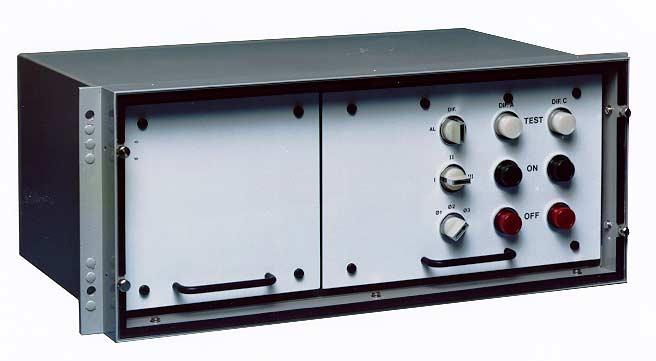
33 BUS2000-Test Rack 33

34 BUS2000-Numerical Monitoring Module 34
35 External Connections Diagram of Single Busbar BUS2000 System 35
36 BUS2000-Settings K for Sensitivity K and RE as low as possible RE for CT requirements for Overvoltage Conditions 36
37 Key Advantages Flexibility Independent setttings for K and RE done in the field without any additional changes Wide Setting Range Suitable for all kinds of installations Measurement Units Supervision Current Circuits Supervision 37
38 Key Advantages (cont d) Single-Three Phase Breaker Failure Test Rack Independent from the protection Easy Commisioning (accesible terminal blocks) Suitable for updating of old Substations Operating Principles well proven in the field Numerical Monitoring Module 38
Bus Protection Fundamentals
 Bus Protection Fundamentals Terrence Smith GE Grid Solutions 2017 Texas A&M Protective Relay Conference Bus Protection Requirements High bus fault currents due to large number of circuits connected: CT
2015 Relay School Bus Protection Mike Kockott March, 2015
 2015 Relay School Bus Protection Mike Kockott March, 2015 History of Bus Protection Circulating current differential (1900s) High impedance differential (1940s) Percentage restrained differential (1960s)
Transformer protection IED RET 670
 Gunnar Stranne Transformer protection IED RET 670 Santiago Septiembre 5, 2006 1 Transformer protection IED RET670 2 Introduction features and applications Differential protection functions Restricted Earth
Application of Low-Impedance 7SS601 Busbar Differential Protection
 Application of Low-Impedance 7SS601 Busbar Differential Protection 1. Introduction Utilities have to supply power to their customers with highest reliability and minimum down time. System disturbances,
Centralized busbar differential and breaker failure protection function
 Centralized busbar differential and breaker failure protection function Budapest, December 2015 Centralized busbar differential and breaker failure protection function Protecta provides two different types
NOVEL PROTECTION SYSTEMS FOR ARC FURNACE TRANSFORMERS
 NOVEL PROTECTION SYSTEMS FOR ARC FURNACE TRANSFORMERS Ljubomir KOJOVIC Cooper Power Systems - U.S.A. Lkojovic@cooperpower.com INTRODUCTION In steel facilities that use Electric Arc Furnaces (EAFs) to manufacture
Power System Protection Part VII Dr.Prof.Mohammed Tawfeeq Al-Zuhairi. Differential Protection (Unit protection)
") Differential Protection (Unit protection) Differential Protection Differential protection is the best technique in protection. In this type of protection the electrical quantities entering and leaving
Differential Protection (Unit protection) Differential Protection Differential protection is the best technique in protection. In this type of protection the electrical quantities entering and leaving
Transformer Protection
 Transformer Protection Transformer Protection Outline Fuses Protection Example Overcurrent Protection Differential Relaying Current Matching Phase Shift Compensation Tap Changing Under Load Magnetizing
Appendix S: PROTECTION ALTERNATIVES FOR VARIOUS GENERATOR CONFIGURATIONS
 Appendix S: PROTECTION ALTERNATIVES FOR VARIOUS GENERATOR CONFIGURATIONS S1. Standard Interconnection Methods with Typical Circuit Configuration for Single or Multiple Units Note: The protection requirements
INSTRUCTION MANUAL BUSBAR PROTECTION RELAY GRB100 - B
 INSTRUCTION MANUAL BUSBAR PROTECTION RELAY GRB00 - B ( Channel/ BU) Toshiba Energy Systems & Solutions Corporation 207 All Rights Reserved. ( Ver. 3.6) Safety Precautions Before using this product, be
Application Guide High Impedance Differential Protection Using SIEMENS 7SJ602
 Application Guide High Impedance Differential Protection Using SIEMENS 7SJ602 1 / 12 1 INTRODUCTION This document provides guidelines for the performance calculations required for high impedance differential
Experiences on using gapless waveform data & synchronized harmonic phasors
 1 Panel Session: New Techniques for Power Quality Measurement and Field Experiences 15PESGM3040 Experiences on using gapless waveform data & synchronized harmonic phasors Wilsun Xu University of Alberta
Numbering System for Protective Devices, Control and Indication Devices for Power Systems
 Appendix C Numbering System for Protective Devices, Control and Indication Devices for Power Systems C.1 APPLICATION OF PROTECTIVE RELAYS, CONTROL AND ALARM DEVICES FOR POWER SYSTEM CIRCUITS The requirements
COPYRIGHTED MATERIAL. Index
 Index Note: Bold italic type refers to entries in the Table of Contents, refers to a Standard Title and Reference number and # refers to a specific standard within the buff book 91, 40, 48* 100, 8, 22*,
This webinar brought to you by The Relion Product Family Next Generation Protection and Control IEDs from ABB
 This webinar brought to you by The Relion Product Family Next Generation Protection and Control IEDs from ABB Relion. Thinking beyond the box. Designed to seamlessly consolidate functions, Relion relays
2C73 Setting Guide. High Impedance Differential Relay. relay monitoring systems pty ltd Advanced Protection Devices
 2C73 Setting Guide High Impedance Differential Relay relay monitoring systems pty ltd Advanced Protection Devices 1. INTRODUCTION This document provides guidelines for the performance calculations required
Unit Protection Differential Relays
 Unit Protection PROF. SHAHRAM MONTASER KOUHSARI Current, pu Current, pu Protection Relays - BASICS Note on CT polarity dots Through-current: must not operate Internal fault: must operate The CT currents
Substation applications
 Substation applications To make it easy to choose the right for a protection application, the most typical applications are presented with the type of for them. Each sample application is presented by:
Protecting Large Machines for Arcing Faults
 Protecting Large Machines for Arcing Faults March 2, 2010 INTRODUCTION Arcing faults occur due to dirty insulators or broken strands in the stator windings. Such faults if undetected can lead to overheating
Stabilized Differential Relay SPAD 346. Product Guide
 Issued: July 1998 Status: Updated Version: D/21.03.2006 Data subject to change without notice Features Integrated three-phase differential relay, three-phase overcurrent relay and multiconfigurable earth-fault
Modular range of digital protection relays
 S e p a m s e r i e s 2 0, 4 0, 8 0 Modular range of digital protection relays Fast Dependable Simple Fast response Maximum dependability Your electrical equipment is under control. With Sepam protection
POWER SYSTEM ANALYSIS TADP 641 SETTING EXAMPLE FOR OVERCURRENT RELAYS
 POWER SYSTEM ANALYSIS TADP 641 SETTING EXAMPLE FOR OVERCURRENT RELAYS Juan Manuel Gers, PhD Example - Single Line Example 1 - Data Calculate the following: 1. The three phase short circuit levels on busbars
3 Pole high impedance differential relay 7VH83
 Fig 1. High impedance differential protection relay 7VH83 Features l Integral CT shorting relay. l Robust solid state design. l Inrush stabilisation through filtering. l Fast operating time. l LED indicator.
PROTECTION of electricity distribution networks
 PROTECTION of electricity distribution networks Juan M. Gers and Edward J. Holmes The Institution of Electrical Engineers Contents Preface and acknowledgments x 1 Introduction 1 1.1 Basic principles of
EE 741 Spring Electric Power Distribution Systems An Overview
 EE 741 Spring 2017 Electric Power Distribution Systems An Overview Basic Power System Layout There are over 100 substations in the Las Vegas Valley pic of closest substation Substation Design Substation
Catastrophic Relay Misoperations and Successful Relay Operation
 Catastrophic Relay Misoperations and Successful Relay Operation Steve Turner (Beckwith Electric Co., Inc.) Introduction This paper provides detailed technical analysis of several catastrophic relay misoperations
Distributed busbar differential protection function and breaker failure protection
 Distributed busbar differential protection function and breaker failure protection Document ID: PP-13-21321 Budapest, September 2016. Distributed busbar differential protection function and breaker failure
Sequence Networks p. 26 Sequence Network Connections and Voltages p. 27 Network Connections for Fault and General Unbalances p. 28 Sequence Network
 Preface p. iii Introduction and General Philosophies p. 1 Introduction p. 1 Classification of Relays p. 1 Analog/Digital/Numerical p. 2 Protective Relaying Systems and Their Design p. 2 Design Criteria
2C73 Setting Guide. High Impedance Differential Relay. Advanced Protection Devices. relay monitoring systems pty ltd
 2C73 Setting Guide High Impedance Differential Relay relay monitoring systems pty ltd Advanced Protection Devices 1. INTRODUCTION This document provides guidelines for the performance calculations required
THE ROLE OF SYNCHROPHASORS IN THE INTEGRATION OF DISTRIBUTED ENERGY RESOURCES
 THE OLE OF SYNCHOPHASOS IN THE INTEGATION OF DISTIBUTED ENEGY ESOUCES Alexander APOSTOLOV OMICON electronics - USA alex.apostolov@omicronusa.com ABSTACT The introduction of M and P class Synchrophasors
889 Advanced Generator Protection Technical Note
 GE Grid Solutions 8 Series 889 Advanced Generator Protection Technical Note GE Publication Number: GET-20056 Copyright 2017 GE Multilin Inc. Overview The Multilin 889 is part of the 8 Series platform that
EE Lecture 14 Wed Feb 8, 2017
 EE 5223 - Lecture 14 Wed Feb 8, 2017 Ongoing List of Topics: URL: http://www.ece.mtu.edu/faculty/bamork/ee5223/index.htm Labs - EE5224 Lab 3 - begins on Tues Feb 14th Term Project - details posted. Limit
Power System Protection Manual
 Power System Protection Manual Note: This manual is in the formative stage. Not all the experiments have been covered here though they are operational in the laboratory. When the full manual is ready,
Protection Relays. U-MLEs-PLv-Ts. Ultra-Ts. DC SUBSTATION PROTECTIVE RELAY (double voltage Line Test) 32, 45, 49, 64, 76, 79, 80
 32, 45, 49, 64, 76, 79, 80") Ultra-Ts DC SUBSTATION PROTECTIVE RELAY (double voltage Line Test) 32, 45, 49, 64, 76, 79, 80 D.C. Feeder protection relay with setting parameters programmable locally or via serial communication. Suitable
Ultra-Ts DC SUBSTATION PROTECTIVE RELAY (double voltage Line Test) 32, 45, 49, 64, 76, 79, 80 D.C. Feeder protection relay with setting parameters programmable locally or via serial communication. Suitable
Summary Paper for C IEEE Guide for Application of Digital Line Current Differential Relays Using Digital Communication
 Summary Paper for C37.243 IEEE Guide for Application of Digital Line Current Differential Relays Using Digital Communication Participants At the time this draft was completed, the D32 Working Group had
PIPSPC. Prepared by Eng: Ahmed Safie Eldin. And. Introduction. Protection Control. Practical. System. Power
 PIPSPC Practical Introduction Power System Protection Control Practical Introduction To Power System Protection And Control Prepared by Eng: Ahmed Safie Eldin 2005 Contents POWER SYSTEMS PRINCIPALS. 1
Generator Protection GENERATOR CONTROL AND PROTECTION
 Generator Protection Generator Protection Introduction Device Numbers Symmetrical Components Fault Current Behavior Generator Grounding Stator Phase Fault (87G) Field Ground Fault (64F) Stator Ground Fault
ABB AG - EPDS. I S -limiter The worldʼs fastest limiting and switching device
 ABB AG - EPDS The worldʼs fastest limiting and switching device Agenda The world s fastest limiting and switching device Customers Function: Insert-holder with insert Comparison: I S -limiter Circuit-breaker
These drawings and single line diagrams provide an outlook of Basler Electric solutions for Excitation System installations and retrofit
 BSLER ELECTRIC DECS EXCITTION SYSTEMS For Retrofitting solutions and New installations These drawings and single line diagrams provide an outlook of Basler Electric solutions for Excitation System installations
Protection Relays. U-MLEs-PLs-Ts. Ultra-Ts. DC SUBSTATION PROTECTIVE RELAY (single voltage Line Test) 32, 45, 49, 64, 76, 79, 80
 32, 45, 49, 64, 76, 79, 80") Ultra-Ts DC SUBSTATION PROTECTIVE RELAY (single voltage Line Test) 32, 45, 49, 64, 76, 79, 80 D.C. Feeder protection relay with setting parameters programmable locally or via serial communication. Suitable
Ultra-Ts DC SUBSTATION PROTECTIVE RELAY (single voltage Line Test) 32, 45, 49, 64, 76, 79, 80 D.C. Feeder protection relay with setting parameters programmable locally or via serial communication. Suitable
PRODUCT TEST MANUAL 2SY110K28 SYNCHRONISM CHECK RELAY
 Sheet 1 of 7 Order Number Serial Number PRODUCT TEST MANUAL 2SY110K28 SYNCHRONISM CHECK RELAY Issue Date Level D 12/12/1996 Initial issue. Summary of changes Due to RMS continuous product improvement policy
N. TEST TEST DESCRIPTION
 Multi function system for testing substation equipment such as: current, voltage and power transformers, all type of protection relays, energy meters and transducers Primary injection testing capabilities
R10. IV B.Tech I Semester Regular/Supplementary Examinations, Nov/Dec SWITCH GEAR AND PROTECTION. (Electrical and Electronics Engineering)
") R10 Set No. 1 Code No: R41023 1. a) Explain how arc is initiated and sustained in a circuit breaker when the CB controls separates. b) The following data refers to a 3-phase, 50 Hz generator: emf between
R10 Set No. 1 Code No: R41023 1. a) Explain how arc is initiated and sustained in a circuit breaker when the CB controls separates. b) The following data refers to a 3-phase, 50 Hz generator: emf between
www. ElectricalPartManuals. com Transformer Differential Relay MD32T Transformer Differential Relay
 Transformer Differential Relay The MD3T Transformer Differential Relay is a member of Cooper Power Systems Edison line of microprocessor based protective relays. The MD3T relay offers the following functions:
POWER SYSTEM PRINCIPLES APPLIED IN PROTECTION PRACTICE. Professor Akhtar Kalam Victoria University
 POWER SYSTEM PRINCIPLES APPLIED IN PROTECTION PRACTICE Professor Akhtar Kalam Victoria University The Problem Calculate & sketch the ZPS, NPS & PPS impedance networks. Calculate feeder faults. Calculate
N. TEST TEST DESCRIPTION
 Multi function system for testing substation equipment such as: current, voltage and power transformers, over-current protection relays, energy meters and transducers Primary injection testing capabilities
Protection Relays. U-MLEs-PLv. Ultra Line. DC SUBSTATION PROTECTIVE RELAY (double voltage Line Test) 32, 45, 49, 64, 76, 79, 80
 32, 45, 49, 64, 76, 79, 80") Ultra Line DC SUBSTATION PROTECTIVE RELAY (double voltage Line Test) 3, 45, 49, 64, 76, 79, 80 D.C. Feeder protection relay with setting parameters programmable locally or via serial communication. Suitable
Ultra Line DC SUBSTATION PROTECTIVE RELAY (double voltage Line Test) 3, 45, 49, 64, 76, 79, 80 D.C. Feeder protection relay with setting parameters programmable locally or via serial communication. Suitable
Busbars and lines are important elements
 CHAPTER CHAPTER 23 Protection of Busbars and Lines 23.1 Busbar Protection 23.2 Protection of Lines 23.3 Time-Graded Overcurrent Protection 23.4 Differential Pilot-Wire Protection 23.5 Distance Protection
ELECTRICAL POWER ENGINEERING
 Introduction This trainer has been designed to provide students with a fully comprehensive knowledge in Electrical Power Engineering systems. The trainer is composed of a set of modules for the simulation
PJM Manual 07:: PJM Protection Standards Revision: 2 Effective Date: July 1, 2016
 PJM Manual 07:: PJM Protection Standards Revision: 2 Effective Date: July 1, 2016 Prepared by System Planning Division Transmission Planning Department PJM 2016 Table of Contents Table of Contents Approval...6
FMR. Ultra Line FEEDER MANAGER RELAY
 Ultra Line FEEDER MANAGER RELAY Protective Functions F49 : One Thermal Image element F50/51/67 : Three levels for phase overcurrent independentely programmable as directional or non directional F50N/51N/67N
Modern transformer relays include a comprehensive set of protective elements to protect transformers from faults and abnormal operating conditions
 1 Transmission transformers are important links in the bulk power system. They allow transfer of power from generation centers, up to the high-voltage grid, and to bulk electric substations for distribution
Extensive LV cable network. Figure 1: Simplified SLD of the transformer and associated LV network
 Copyright 2017 ABB. All rights reserved. 1. Introduction Many distribution networks around the world have limited earth-fault current by a resistor located in the LV winding neutral point of for example
Single Line Diagram of Substations
 Single Line Diagram of Substations Substations Electric power is produced at the power generating stations, which are generally located far away from the load centers. High voltage transmission lines are
Summary Paper for C IEEE Guide for Application of Digital Line Current Differential Relays Using Digital Communication
 Summary Paper for C37.243 IEEE Guide for Application of Digital Line Current Differential Relays Using Digital Communication by: Neftaly Torres, P.E. 70 th Annual Conference for Protective Relay Engineers,
Protection of Microgrids Using Differential Relays
 1 Protection of Microgrids Using Differential Relays Manjula Dewadasa, Member, IEEE, Arindam Ghosh, Fellow, IEEE and Gerard Ledwich, Senior Member, IEEE Abstract A microgrid provides economical and reliable
T/3000 T/3000. Substation Maintenance and Commissioning Test Equipment
 T/3000 Substation Maintenance and Commissioning Test Equipment MULTI FUNCTION SYSTEM FOR TESTING SUBSTATION EQUIPMENT SUCH AS: CURRENT, VOLTAGE AND POWER TRANSFORMERS, ALL TYPE OF PROTECTION RELAYS, ENERGY
High Voltage Busbar Protection
 High Voltage Busbar Protection Course No: E05-012 Credit: 5 PDH Velimir Lackovic, Char. Eng. Continuing Education and Development, Inc. 9 Greyridge Farm Court Stony Point, NY 10980 P: (877) 322-5800 F:
Transformer Fault Categories
 Transformer Fault Categories 1. Winding and terminal faults 2. Sustained or uncleared external faults 3. Abnormal operating conditions such as overload, overvoltage and overfluxing 4. Core faults 1 (1)
Application for A Sub-harmonic Protection Relay. ERLPhase Power Technologies
 Application for A Sub-harmonic Protection Relay ERLPhase Power Technologies 1 Outline Introduction System Event at Xcel Energy Event Analysis Microprocessor based relay hardware architecture Sub harmonic
Power systems Protection course
 Al-Balqa Applied University Power systems Protection course Department of Electrical Energy Engineering 1 Part 5 Relays 2 3 Relay Is a device which receive a signal from the power system thought CT and
www. ElectricalPartManuals. com Generator Differential Relay MD32G Rotating Machine Differential Relay
 Generator Differential Relay The MD3G Rotating Machine Differential Relay is a member of Cooper Power Systems Edison line of microprocessor based protective relays. The MD3G relay offers the following
Protective Relays Digitrip 3000
 New Information Technical Data Effective: May 1999 Page 1 Applications Provides reliable 3-phase and ground overcurrent protection for all voltage levels. Primary feeder circuit protection Primary transformer
High-set undervoltage stage with definitetime. or inverse definite minimum time (IDMT) characteristic. Low-set undervoltage stage with definitetime
 characteristic. Low-set undervoltage stage with definitetime") Issued: 5.06.999 Status: 5.06.999 Version: B/09..00 Data subject to change without notice Features Overvoltage and undervoltage protection Single- or three-phase operation High-set overvoltage stage with
Issued: 5.06.999 Status: 5.06.999 Version: B/09..00 Data subject to change without notice Features Overvoltage and undervoltage protection Single- or three-phase operation High-set overvoltage stage with
Impact of Incipient Faults on Sensitive Protection
 Impact of Incipient Faults on Sensitive Protection Paper Authors: Ilia Voloh GE Grid Solutions Zhihan Xu, Ilia Voloh GE Grid Solutions Leonardo Torelli CSE-Uniserve Presented by: Tom Ernst GE Grid Solutions
presentation contents application advantages
 presentation contents page presentation protection functional and connection schemes other connection schemes connection characteristics 9 installation 0 commissioning ordering information Sepam 00 is
APPLICATION: The heart of the system is a DSR 100 Digital Static Regulator used in conjunction with standard SCR based rectifier bridges.
 APPLICATION: Basler Electric offers a New Line of digitally controlled brush (static) or brushless excitation systems designed for use with existing Hydro, Gas as well as Diesel driven generators requiring
System Protection and Control Subcommittee
 Power Plant and Transmission System Protection Coordination Reverse Power (32), Negative Sequence Current (46), Inadvertent Energizing (50/27), Stator Ground Fault (59GN/27TH), Generator Differential (87G),
Substation Automation Products. Distributed busbar protection REB500 including line and transformer protection Product Guide
 Distributed busbar protection REB Product Guide Distributed busbar protection REB Main features Low-impedance busbar protection Stub and T-zone protection High functional reliability due to two independent
2V68-S User Guide. CT Supervision And Shorting Relay. User Guide
 2V68-S User Guide CT Supervision And Shorting Relay User Guide Visit www.rmspl.com.au for the latest product information. Due to RMS continuous product improvement policy this information is subject to
SPAD 346 C Stabilized differential relay
 SPAD 346 C Stabilized differential relay Stabilized Differential Relay Type SPAD 346 C Features Integrated three-phase differential relay, three-phase overcurrent relay and multiconfigurable earth-fault
Fixed Series Compensation
 Fixed Series Compensation High-reliable turnkey services for fixed series compensation NR Electric Corporation The Fixed Series Compensation (FSC) solution is composed of NR's PCS-9570 FSC control and
Redundant Bus Protection Using High-Impedance Differential Relays
 Redundant Bus Protection Using High-Impedance Relays Josh LaBlanc, Schweitzer Engineering Laboratories, Inc. (formerly of Minnesota Power) Michael Thompson, Schweitzer Engineering Laboratories, Inc. 2018
Power Plant and Transmission System Protection Coordination Fundamentals
 Power Plant and Transmission System Protection Coordination Fundamentals NERC Protection Coordination Webinar Series June 2, 2010 Jon Gardell Agenda 2 Objective Introduction to Protection Generator and
Detecting and Managing Geomagnetically Induced Currents With Relays
 Detecting and Managing Geomagnetically Induced Currents With Relays Copyright SEL 2013 Transformer Relay Connections Voltage Current Control RTDs Transformer Protective Relay Measures differential current
NTG MULTIFUNCTON GENERATOR PROTECTION RELAY. NTG-Slide
 NTG MULTIFUNCTON GENERATOR PROTECTION RELAY 1 NTG Digital protection relay that integrates a number of functions required r for the protection of generators. It is used in power stations from gas, steam,
Protection Basics Presented by John S. Levine, P.E. Levine Lectronics and Lectric, Inc GE Consumer & Industrial Multilin
 Protection Basics Presented by John S. Levine, P.E. Levine Lectronics and Lectric, Inc. 770 565-1556 John@L-3.com 1 Protection Fundamentals By John Levine 2 Introductions Tools Outline Enervista Launchpad
Generator Protection M 3425
 PROTECTION Generator Protection M 3425 Integrated Protection System for Generators of All Sizes Unit shown with optional M 3925 Target Module and M 3931 HMI (Human Machine Interface) Module Provides all
Protection of Electrical Networks. Christophe Prévé
 Protection of Electrical Networks Christophe Prévé This Page Intentionally Left Blank Protection of Electrical Networks This Page Intentionally Left Blank Protection of Electrical Networks Christophe Prévé
Končar TMS - Bushing monitoring
 Končar TMS - Bushing monitoring Many recent studies have shown that bushing failure is one of the most common causes of transformer failure. Thus need for bushing diagnostic and monitoring system has risen.
Electrical Protection System Design and Operation
 ELEC9713 Industrial and Commercial Power Systems Electrical Protection System Design and Operation 1. Function of Electrical Protection Systems The three primary aims of overcurrent electrical protection
RAIDK, RAIDG, RAPDK and RACIK Phase overcurrent and earth-fault protection assemblies based on single phase measuring elements
 RAIDK, RAIDG, RAPDK and RACIK Phase overcurrent and earth-fault protection assemblies based on single phase measuring elements User s Guide General Most faults in power systems can be detected by applying
Fuseless Capacitor Bank Protection
 Fuseless Bank Protection Minnesota Power Systems Conference St. Paul, MN. November 2, 1999 by: Tom Ernst, Minnesota Power Other Papers of Interest Presented at Western Protective Relay Conference, Oct.
Earth Fault Protection
 Earth Fault Protection Course No: E03-038 Credit: 3 PDH Velimir Lackovic, Char. Eng. Continuing Education and Development, Inc. 9 Greyridge Farm Court Stony Point, NY 10980 P: (877) 322-5800 F: (877) 322-4774
PROTECTIVE RELAY MISOPERATIONS AND ANALYSIS
 PROTECTIVE RELAY MISOPERATIONS AND ANALYSIS BY STEVE TURNER, Beckwith Electric Company, Inc. This paper provides detailed technical analysis of two relay misoperations and demonstrates how to prevent them
Unit 2. Single Line Diagram of Substations
 Unit 2 Single Line Diagram of Substations Substations Electric power is produced at the power generating stations, which are generally located far away from the load centers. High voltage transmission
Using a Multiple Analog Input Distance Relay as a DFR
 Using a Multiple Analog Input Distance Relay as a DFR Dennis Denison Senior Transmission Specialist Entergy Rich Hunt, M.S., P.E. Senior Field Application Engineer NxtPhase T&D Corporation Presented at
Generator Protection M 3420
 PROTECTION Generator Protection M 3420 Integrated Protection System for Generators of All Sizes Unit shown with optional M 3920 Target Module and M 3931 HMI (Human-Machine Interface) Module Microprocessor-based
NERC Protection Coordination Webinar Series July 15, Jon Gardell
 Power Plant and Transmission System Protection Coordination Reverse Power (32), Negative Sequence Current (46), Inadvertent Energizing (50/27), Stator Ground Fault (59GN/27TH), Generator Differential (87G),
Power System Protection. Dr. Lionel R. Orama Exclusa, PE Week 3
 Power System Protection Dr. Lionel R. Orama Exclusa, PE Week 3 Operating Principles: Electromagnetic Attraction Relays Readings-Mason Chapters & 3 Operating quantities Electromagnetic attraction Response
Babak Enayati National Grid Thursday, April 17
 2014 IEEE PES Transmission & Distribution Conference & Exposition Impacts of the Distribution System Renewable Energy Resources on the Power System Protection Babak Enayati National Grid Thursday, April
Reyrolle Protection Devices. 7PG21 Solkor R/Rf Pilot Wire Current Differential Protection. Answers for energy
 Reyrolle Protection Devices 7PG21 Solkor R/Rf Pilot Wire Current Differential Protection Answers for energy 7PG21 Solkor R/Rf Pilot Wire Current Differential Protection Additional Options 15kV Isolation
ARC FLASH HAZARD ANALYSIS AND MITIGATION
 ARC FLASH HAZARD ANALYSIS AND MITIGATION J.C. Das IEEE PRESS SERIES 0N POWER ENGINEERING Mohamed E. El-Hawary, Series Editor IEEE IEEE PRESS WILEY A JOHN WILEY & SONS, INC., PUBLICATION CONTENTS Foreword
NORTH CAROLINA INTERCONNECTION REQUEST. Utility: Designated Contact Person: Address: Telephone Number: Address:
 NORTH CAROLINA INTERCONNECTION REQUEST Utility: Designated Contact Person: Address: Telephone Number: Fax: E-Mail Address: An is considered complete when it provides all applicable and correct information
Replacement solution
 Replacement solution for the ABB DPU2000R protection and control relay Specification File, Revision, Date (Pages) Replacement Relay Specification_ABB DPU2000R_0.doc, Revision 0, August 2, 2013 (37) Table
Transformer Protection Principles
 Transformer Protection Principles 1. Introduction Transformers are a critical and expensive component of the power system. Due to the long lead time for repair of and replacement of transformers, a major
Back to the Basics Event Analysis Using Symmetrical Components
 Back to the Basics Event Analysis Using Symmetrical Components Amanvir Sudan Schweitzer Engineering Laboratories, Inc. 218 SEL Motivation Overview Back to Basics Introduction Symmetrical components refresher
7SG14 Duobias M Transformer Protection Answers for energy
 Reyrolle Protection Devices 7SG14 Duobias M Transformer Protection Answers for energy 7SG14 Duobias-M-200 Contents Contents Technical Manual Chapters 1. Description of Operation 2. Performance Specification
SYNCHRONISING AND VOLTAGE SELECTION
 SYNCHRONISING AND VOLTAGE SELECTION This document is for Relevant Electrical Standards document only. Disclaimer NGG and NGET or their agents, servants or contractors do not accept any liability for any
GENERATOR INTERCONNECTION APPLICATION Category 5 For All Projects with Aggregate Generator Output of More Than 2 MW
 GENERATOR INTERCONNECTION APPLICATION Category 5 For All Projects with Aggregate Generator Output of More Than 2 MW ELECTRIC UTILITY CONTACT INFORMATION Consumers Energy Interconnection Coordinator 1945