POWER SYSTEM PRINCIPLES APPLIED IN PROTECTION PRACTICE. Professor Akhtar Kalam Victoria University
|
|
|
- Dulcie Russell
- 6 years ago
- Views:
Transcription
1 POWER SYSTEM PRINCIPLES APPLIED IN PROTECTION PRACTICE Professor Akhtar Kalam Victoria University
2 The Problem Calculate & sketch the ZPS, NPS & PPS impedance networks. Calculate feeder faults. Calculate transmission line fault current. Specify suitable CTs for protection scheme. Design Over-current protection for the 22kV feeders, busbar and 66/22 kv transformer Specify and design Distance Protection that will coordinate with Over-current protection scheme above.
3 POWER SYSTEM UTM SKUDAI
4
5
6 PPS, NPS and ZPS Calculations For a fault F, at the end of the 22 kv feeder, sketch the positive phase sequence (PPS), negative phase sequence (NPS) and zero phase sequence (ZPS) impedance networks. Show the value of all impedances as % on a 25 MVA base.
7 THE DESIGN
8 FAULT CALCULATION
9
10
11
12
13
14
15
16
17 Calculate the currents at the fault F, for a three-phase short-circuit and an a -phase-to-ground short-circuit.
18

19
20
21
22
23 Calculate the current in each phase of the two 66 kv lines for the a--phase-to-ground fault at F. Remember that a delta/star transformation shifts the PPS and NPS currents each 30 in opposite directions.
24
25

26
27
28
29
30
31
32
33
34 Specify a suitable CT'B' for the 22 kv feeders, giving a ratio and a performance specification suitable for protections applicable to distribution systems, i.e. protections which operate in greater than 0.2 second. You can assume that the rated load current of the 22 kv switchgear is 400 amps, that the rated fault capacity is 250 MVA, that the secondary equipment has a 5-amp rating and that the total burden represented by the leads and the relays is 0.7 ohms.
35
36
37
38 Specify suitable CT's 'C' for transformer protection and 'A' for 66 kv line protection. Both protections will be required to operate in less than 0.2 second. The power system X / R is to be taken as 4. Design CT 'A' for maximum 22 kv faults. 66 kv CB load current rating is 600 amps, and fault rating at the 220/66 kv station 66 kv bus is 2500 MVA. Burden of leads plus relay is 0.7 ohm. 66/22 kv transformer cyclic rating is 1.2 times nominal. Remember that the exciting current you specify is a measure of the composite error and size of the CT core.
39
40
41
42
43
44
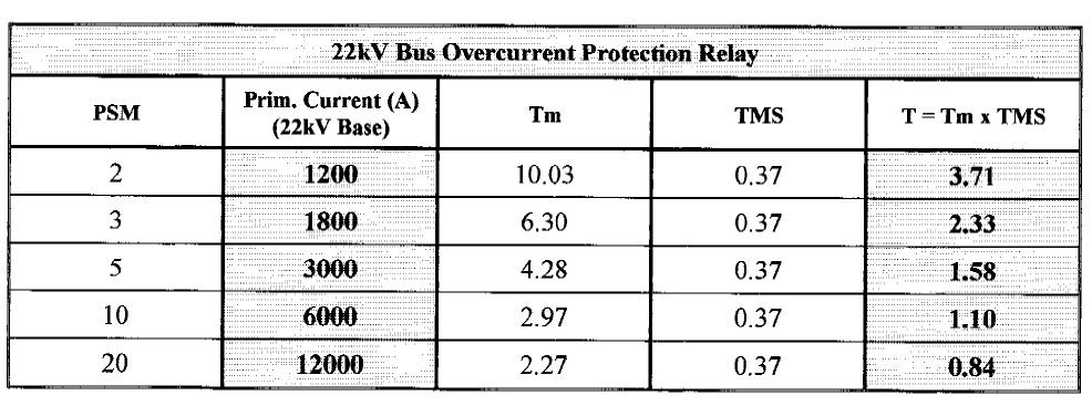
45 It is planned to apply overcurrent protections to the 22 kv feeders, 22 kv busbars and 66 kv transformer connections of the system shown on Figure 1. CT connections and ratios are shown in Figure 2. Determine minimum operating currents and plot the time/current curves for the three overcurrent protections, showing discriminating margins. Use CDG11 inverse definite minimum-time overcurrent 3-second relays [Reference A.Kalam et. al., Power system Protection, Figure 2b, page 5-23]. The bus overcurrent protection is to be set to provide backup for failure of the 22 kv feeder protection and the transformer overcurrent to backup for failure of the bus protection. The time current curves should be plotted on the log-log graph paper provided. Base the settings on the three-phase fault currents that you calculated in earlier parts. Assume the CDG 11 relay has plug settings of 1, 2, 2.5, 3.75 and 5 amps.
46


47
48
49
50
51
52
53
54

55

56
57
58 A three-zone distance protection is planned for the protection of the 66 kv line 2 in the system on figure 1 (connected to CT 'C' at the 220 kv station end). Assume that the zone 3 characteristic is an offset mho with 20% reverse reach and that zones 1 and 2 have an mho characteristic. Relay characteristic angle is 60. Zone 3 reach is to be set to provide backup for failure of transformer protection. (i) List the measuring elements that comprise a full distance scheme and the voltages and currents measured by each element. (ii) Select suitable impedance settings, in primary ohms, for each zone and plot your results on an X-R polar diagram. Show the likely locus of the load under all possible operating conditions, given that the emergency rating of the 22 kv station is 120% of one transformer. (iii) Select zone time settings that will coordinate with the overcurrent protection settings calculated in part (f). (iv) Using current and voltage sequence components, calculate the current, voltage and impedance measured by the b-c phase element of the distance relay for a b-c phase fault at the end of the 66 kv line. Remember that the PPS voltage at the fault is determined by the voltage drop from the source to the fault, through the PPS impedance network and the NPS voltage is maximum at the fault and zero at the source. Calculate the PPS and NPS at the relay location by proportion and add vectorially to obtain the actual voltage.
59
60
61
62
63
64
65
66
67
68
69
70
71
72
73
74
75
76
77
78
79
POWER SYSTEM ANALYSIS TADP 641 SETTING EXAMPLE FOR OVERCURRENT RELAYS
 POWER SYSTEM ANALYSIS TADP 641 SETTING EXAMPLE FOR OVERCURRENT RELAYS Juan Manuel Gers, PhD Example - Single Line Example 1 - Data Calculate the following: 1. The three phase short circuit levels on busbars
Transmission Lines and Feeders Protection Pilot wire differential relays (Device 87L) Distance protection
 Distance protection") Transmission Lines and Feeders Protection Pilot wire differential relays (Device 87L) Distance protection 133 1. Pilot wire differential relays (Device 87L) The pilot wire differential relay is a high-speed
Transmission Lines and Feeders Protection Pilot wire differential relays (Device 87L) Distance protection 133 1. Pilot wire differential relays (Device 87L) The pilot wire differential relay is a high-speed
3. (a) List out the advantages and disadvantages of HRC fuse (b) Explain fuse Characteristics in detail. [8+8]
![3. (a) List out the advantages and disadvantages of HRC fuse (b) Explain fuse Characteristics in detail. [8+8]](/thumbs/77/76027701.jpg "3. (a) List out the advantages and disadvantages of HRC fuse (b) Explain fuse Characteristics in detail. [8+8]") Code No: RR320205 Set No. 1 1. (a) Explain about Bewley s Lattice diagrams and also mention the uses of these diagrams. [6+2] (b) A line of surge impedance of 400 ohms is charged from a battery of constant
Code No: RR320205 Set No. 1 1. (a) Explain about Bewley s Lattice diagrams and also mention the uses of these diagrams. [6+2] (b) A line of surge impedance of 400 ohms is charged from a battery of constant
UNIVERSITY OF SWAZILAND
 UNVERSTY OF SWAZLAND SUPPLEMENTARY EXAMNATON, SECOND SEMESTER MAY 2017 FACULTY OF SCENCE AND ENGNEERNG DEPARTMENT OF ELECTRCAL AND ELECTRONC ENGNEERNG TTLE OF PAPER: Switchgear and Protection COURSE CODE
Transformer Protection
 Transformer Protection Transformer Protection Outline Fuses Protection Example Overcurrent Protection Differential Relaying Current Matching Phase Shift Compensation Tap Changing Under Load Magnetizing
Electrical Protection System Design and Operation
 ELEC9713 Industrial and Commercial Power Systems Electrical Protection System Design and Operation 1. Function of Electrical Protection Systems The three primary aims of overcurrent electrical protection
Protection Basics Presented by John S. Levine, P.E. Levine Lectronics and Lectric, Inc GE Consumer & Industrial Multilin
 Protection Basics Presented by John S. Levine, P.E. Levine Lectronics and Lectric, Inc. 770 565-1556 John@L-3.com 1 Protection Fundamentals By John Levine 2 Introductions Tools Outline Enervista Launchpad
Protective Relays Digitrip 3000
 New Information Technical Data Effective: May 1999 Page 1 Applications Provides reliable 3-phase and ground overcurrent protection for all voltage levels. Primary feeder circuit protection Primary transformer
POWER SYSTEM ANALYSIS TADP 641 SETTING OF OVERCURRENT RELAYS
 POWER SYSTEM ANALYSIS TADP 641 SETTING OF OVERCURRENT RELAYS Juan Manuel Gers, PhD Protection coordination principles Relay coordination is the process of selecting settings that will assure that the relays
Bus Protection Fundamentals
 Bus Protection Fundamentals Terrence Smith GE Grid Solutions 2017 Texas A&M Protective Relay Conference Bus Protection Requirements High bus fault currents due to large number of circuits connected: CT
9 Overcurrent Protection for Phase and Earth Faults
 Overcurrent Protection for Phase and Earth Faults Introduction 9. Co-ordination procedure 9.2 Principles of time/current grading 9.3 Standard I.D.M.T. overcurrent relays 9.4 Combined I.D.M.T. and high
SCHEME OF COURSE WORK ( ) Electrical & Electronics Engineering. Electrical machines-i, II and power transmission engineering
 Electrical & Electronics Engineering. Electrical machines-i, II and power transmission engineering") SCHEME OF COURSE WORK (2015-2016) COURSE DETAILS: Course Title Course Code Program Branch Semester Prerequisites Course to which it is prerequisite Switchgear and Protection 15EE1116 B.Tech Electrical
SCHEME OF COURSE WORK (2015-2016) COURSE DETAILS: Course Title Course Code Program Branch Semester Prerequisites Course to which it is prerequisite Switchgear and Protection 15EE1116 B.Tech Electrical
Course No: 1 13 (3 Days) FAULT CURRENT CALCULATION & RELAY SETTING & RELAY CO-ORDINATION. Course Content
 FAULT CURRENT CALCULATION & RELAY SETTING & RELAY CO-ORDINATION. Course Content") Course No: 1 13 (3 Days) FAULT CURRENT CALCULATION & RELAY SETTING & RELAY CO-ORDINATION Sr. No. Course Content 1.0 Fault Current Calculations 1.1 Introduction to per unit and percentage impedance 1.2
Course No: 1 13 (3 Days) FAULT CURRENT CALCULATION & RELAY SETTING & RELAY CO-ORDINATION Sr. No. Course Content 1.0 Fault Current Calculations 1.1 Introduction to per unit and percentage impedance 1.2
A Tutorial on the Application and Setting of Collector Feeder Overcurrent Relays at Wind Electric Plants
 A Tutorial on the Application and Setting of Collector Feeder Overcurrent Relays at Wind Electric Plants Martin Best and Stephanie Mercer, UC Synergetic, LLC Abstract Wind generating plants employ several
NERC Protection Coordination Webinar Series June 16, Phil Tatro Jon Gardell
 Power Plant and Transmission System Protection Coordination Phase Distance (21) and Voltage-Controlled or Voltage-Restrained Overcurrent Protection (51V) NERC Protection Coordination Webinar Series June
BUS2000 Busbar Differential Protection System
 BUS2000 Busbar Differential Protection System Differential overcurrent system with percentage restraint protection 1 Typical Busbar Arrangements Single Busbar Double Busbar with Coupler Breaker and a Half
Time-current Coordination
 269 5.2.3.1 Time-current Coordination Time that is controlled by current magnitude permits discriminating faults at one location from another. There are three variables available to discriminate faults,
Types CDG 11 and CDG 16 Inverse Time Overcurrent and Earth Fault Relay
 Types CDG 11 and CDG 16 Inverse Time Overcurrent and Earth Fault Relay Types CDG 11 and CDG 16 Inverse Time Overcurrent and Earth Fault Relay Relay withdrawn from case Application The type CDG 11 relay
Unit Protection Differential Relays
 Unit Protection PROF. SHAHRAM MONTASER KOUHSARI Current, pu Current, pu Protection Relays - BASICS Note on CT polarity dots Through-current: must not operate Internal fault: must operate The CT currents
Protection Introduction
 1.0 Introduction Protection 2 There are five basic classes of protective relays: Magnitude relays Directional relays Ratio (impedance) relays Differential relays Pilot relays We will study each of these.
NERC Requirements for Setting Load-Dependent Power Plant Protection: PRC-025-1
 NERC Requirements for Setting Load-Dependent Power Plant Protection: PRC-025-1 Charles J. Mozina, Consultant Beckwith Electric Co., Inc. www.beckwithelectric.com I. Introduction During the 2003 blackout,
PROTECTION of electricity distribution networks
 PROTECTION of electricity distribution networks Juan M. Gers and Edward J. Holmes The Institution of Electrical Engineers Contents Preface and acknowledgments x 1 Introduction 1 1.1 Basic principles of
Figure 1 System One Line
 Fault Coverage of Memory Polarized Mho Elements with Time Delays Hulme, Jason Abstract This paper analyzes the effect of time delays on the fault resistance coverage of memory polarized distance elements.
Back to the Basics Current Transformer (CT) Testing
 Testing") Back to the Basics Current Transformer (CT) Testing As test equipment becomes more sophisticated with better features and accuracy, we risk turning our field personnel into test set operators instead of
Back to the Basics Current Transformer (CT) Testing As test equipment becomes more sophisticated with better features and accuracy, we risk turning our field personnel into test set operators instead of
Generator Protection GENERATOR CONTROL AND PROTECTION
 Generator Protection Generator Protection Introduction Device Numbers Symmetrical Components Fault Current Behavior Generator Grounding Stator Phase Fault (87G) Field Ground Fault (64F) Stator Ground Fault
Relaying 101. by: Tom Ernst GE Grid Solutions
 Relaying 101 by: Tom Ernst GE Grid Solutions Thomas.ernst@ge.com Relaying 101 The abridged edition Too Much to Cover Power system theory review Phasor domain representation of sinusoidal waveforms 1-phase
Impedance protection on power transformer.
 Impedance protection on power transformer www.siemens.com/siprotec5 SIPROTEC 5 Application Impedance Protection on Power Transformer APN-045, Edition 1 Content 1...3 1.1 Introduction...3 1.2 Application
Busbars and lines are important elements
 CHAPTER CHAPTER 23 Protection of Busbars and Lines 23.1 Busbar Protection 23.2 Protection of Lines 23.3 Time-Graded Overcurrent Protection 23.4 Differential Pilot-Wire Protection 23.5 Distance Protection
NERC Protection Coordination Webinar Series June 9, Phil Tatro Jon Gardell
 Power Plant and Transmission System Protection Coordination GSU Phase Overcurrent (51T), GSU Ground Overcurrent (51TG), and Breaker Failure (50BF) Protection NERC Protection Coordination Webinar Series
1 INTRODUCTION 1.1 PRODUCT DESCRIPTION
 GEK-00682D INTRODUCTION INTRODUCTION. PRODUCT DESCRIPTION The MDP Digital Time Overcurrent Relay is a digital, microprocessor based, nondirectional overcurrent relay that protects against phase-to-phase
Transformer Fault Categories
 Transformer Fault Categories 1. Winding and terminal faults 2. Sustained or uncleared external faults 3. Abnormal operating conditions such as overload, overvoltage and overfluxing 4. Core faults 1 (1)
Power System Protection Manual
 Power System Protection Manual Note: This manual is in the formative stage. Not all the experiments have been covered here though they are operational in the laboratory. When the full manual is ready,
Relay Coordination in the Protection of Radially- Connected Power System Network
 Relay Coordination in the Protection of Radially- Connected Power System Network Zankhana Shah Electrical Department, Kalol institute of research centre, Ahemedabad-Mehshana Highway, kalol, India 1 zankhu.shah@gmail.com
Impact of transient saturation of Current Transformer during cyclic operations Analysis and Diagnosis
 1 Impact of transient saturation of Current Transformer during cyclic operations Analysis and Diagnosis BK Pandey, DGM(OS-Elect) Venkateswara Rao Bitra, Manager (EMD Simhadri) 1.0 Introduction: Current
PRC Generator Relay Loadability. Guidelines and Technical Basis Draft 5: (August 2, 2013) Page 1 of 76
 Page 1 of 76") PRC-025-1 Introduction The document, Power Plant and Transmission System Protection Coordination, published by the NERC System Protection and Control Subcommittee (SPCS) provides extensive general discussion
PRC-025-1 Introduction The document, Power Plant and Transmission System Protection Coordination, published by the NERC System Protection and Control Subcommittee (SPCS) provides extensive general discussion
Mho. MiCOMho P443. A Guide How To Draw and Test P443 Distance Characteristics using Omicron
 Mho MiCOMho P443 A Guide How To Draw and Test P443 Distance Characteristics using Omicron This document serves as a guide how to draw P443 Mho and Quad characteristics. P443 is a self+memory polarised
U I. Time Overcurrent Relays. Basic equation. More or less approximates thermal fuse. » Allow coordination with fuses 9/24/2018 ECE525.
 Time Overcurrent Relays More or less approximates thermal fuse» Allow coordination with fuses Direction of Current nduced Torque Restraining Spring Reset Position Time Dial Setting Disk Basic equation
Numbering System for Protective Devices, Control and Indication Devices for Power Systems
 Appendix C Numbering System for Protective Devices, Control and Indication Devices for Power Systems C.1 APPLICATION OF PROTECTIVE RELAYS, CONTROL AND ALARM DEVICES FOR POWER SYSTEM CIRCUITS The requirements
Application of Low-Impedance 7SS601 Busbar Differential Protection
 Application of Low-Impedance 7SS601 Busbar Differential Protection 1. Introduction Utilities have to supply power to their customers with highest reliability and minimum down time. System disturbances,
PRC Generator Relay Loadability. Guidelines and Technical Basis Draft 4: (June 10, 2013) Page 1 of 75
 Page 1 of 75") PRC-025-1 Introduction The document, Power Plant and Transmission System Protection Coordination, published by the NERC System Protection and Control Subcommittee (SPCS) provides extensive general discussion
PRC-025-1 Introduction The document, Power Plant and Transmission System Protection Coordination, published by the NERC System Protection and Control Subcommittee (SPCS) provides extensive general discussion
A Guide to the DC Decay of Fault Current and X/R Ratios
 A Guide to the DC Decay of Fault Current and X/R Ratios Introduction This guide presents a guide to the theory of DC decay of fault currents and X/R ratios and the calculation of these values in Ipsa.
EARTH FAULT PROTECTION VIS-A-VIS GENERATOR GROUNDING SYSTEM
 EARTH FAULT PROTECTION VIS-A-VIS GENERATOR GROUNDING SYSTEM BY MR. H. C. MEHTA AT 1 ST INDIA DOBLE PROTECTION AND AUTOMATION CONFERENCE, NOV 2008 POWER-LINKER Wisdom is not Virtue but Necessity hcmehta@powerlinker.org
Power Plant and Transmission System Protection Coordination of-field (40) and Out-of. of-step Protection (78)
 and Out-of. of-step Protection (78)") Power Plant and Transmission System Protection Coordination Loss-of of-field (40) and Out-of of-step Protection (78) System Protection and Control Subcommittee Protection Coordination Workshop Phoenix,
Power Plant and Transmission System Protection Coordination Loss-of of-field (40) and Out-of of-step Protection (78) System Protection and Control Subcommittee Protection Coordination Workshop Phoenix,
Notes 1: Introduction to Distribution Systems
 Notes 1: Introduction to Distribution Systems 1.0 Introduction Power systems are comprised of 3 basic electrical subsystems. Generation subsystem Transmission subsystem Distribution subsystem The subtransmission
Jonathan (Xiangmin) Gao - GE Grid Solutions Douglas Rust - Dandsco LLC Presented by: Tom Ernst GE Grid Solutions
 Gao - GE Grid Solutions Douglas Rust - Dandsco LLC Presented by: Tom Ernst GE Grid Solutions") Jonathan (Xiangmin) Gao - GE Grid Solutions Douglas Rust - Dandsco LLC Presented by: Tom Ernst GE Grid Solutions PRC-001: System protection coordination PRC-019: Coordination with voltage regulating control
Jonathan (Xiangmin) Gao - GE Grid Solutions Douglas Rust - Dandsco LLC Presented by: Tom Ernst GE Grid Solutions PRC-001: System protection coordination PRC-019: Coordination with voltage regulating control
R10. IV B.Tech I Semester Regular/Supplementary Examinations, Nov/Dec SWITCH GEAR AND PROTECTION. (Electrical and Electronics Engineering)
") R10 Set No. 1 Code No: R41023 1. a) Explain how arc is initiated and sustained in a circuit breaker when the CB controls separates. b) The following data refers to a 3-phase, 50 Hz generator: emf between
R10 Set No. 1 Code No: R41023 1. a) Explain how arc is initiated and sustained in a circuit breaker when the CB controls separates. b) The following data refers to a 3-phase, 50 Hz generator: emf between
Redundant Bus Protection Using High-Impedance Differential Relays
 Redundant Bus Protection Using High-Impedance Relays Josh LaBlanc, Schweitzer Engineering Laboratories, Inc. (formerly of Minnesota Power) Michael Thompson, Schweitzer Engineering Laboratories, Inc. 2018
Current Transformer Requirements for VA TECH Reyrolle ACP Relays. PREPARED BY:- A Allen... APPROVED :- B Watson...
 TECHNICAL REPORT APPLICATION GUIDE TITLE: Current Transformer Requirements for VA TECH Reyrolle ACP Relays PREPARED BY:- A Allen... APPROVED :- B Watson... REPORT NO:- 990/TIR/005/02 DATE :- 24 Jan 2000
Modeling and Performance Analysis of Mho-Relay in Matlab
 Modeling and Performance Analysis of Mho-Relay in Matlab Purra Sai Kiran M.Tech Student, Padmasri Dr. B V Raju Institute of Technology, Narsapur, Medak, Telangana. ABSTRACT: This paper describes the opportunity
RAIDK, RAIDG, RAPDK and RACIK Phase overcurrent and earth-fault protection assemblies based on single phase measuring elements
 RAIDK, RAIDG, RAPDK and RACIK Phase overcurrent and earth-fault protection assemblies based on single phase measuring elements User s Guide General Most faults in power systems can be detected by applying
Line Protection Roy Moxley Siemens USA
 Line Protection Roy Moxley Siemens USA Unrestricted Siemens AG 2017 siemens.com/digitalgrid What is a Railroad s Biggest Asset? Rolling Stock Share-holders Relationships Shipping Contracts Employees (Engineers)
Setting and Verification of Generation Protection to Meet NERC Reliability Standards
 1 Setting and Verification of Generation Protection to Meet NERC Reliability Standards Xiangmin Gao, Tom Ernst Douglas Rust, GE Energy Connections Dandsco LLC. Abstract NERC has recently published several
Distance Element Performance Under Conditions of CT Saturation
 Distance Element Performance Under Conditions of CT Saturation Joe Mooney Schweitzer Engineering Laboratories, Inc. Published in the proceedings of the th Annual Georgia Tech Fault and Disturbance Analysis
Coordination of protective relays in MV transformer stations using EasyPower Protector software
 Coordination of protective relays in MV transformer stations using EasyPower Protector software S. Nikolovski, Member, IEEE, I. Provci and D. Sljivac In this paper, the analysis of digital protection relays
Optimum Coordination of Overcurrent Relays: GA Approach
 Optimum Coordination of Overcurrent Relays: GA Approach 1 Aesha K. Joshi, 2 Mr. Vishal Thakkar 1 M.Tech Student, 2 Asst.Proff. Electrical Department,Kalol Institute of Technology and Research Institute,
Motor Protection. May 31, Tom Ernst GE Grid Solutions
 Motor Protection May 31, 2017 Tom Ernst GE Grid Solutions Motor Relay Zone of Protection -Electrical Faults -Abnormal Conditions -Thermal Overloads -Mechanical Failure 2 Setting of the motor protection
Connection Impact Assessment Application
 Connection Impact Assessment Application This form is for generators applying for Connection Impact Assessment (CIA) and for generators with a project size >10 kw. Please return the completed form by email,
Setting Generic Distance Relay UTP-100#WPSC1. in the. Computer-Aided Protection Engineering System (CAPE)
") Setting Generic Distance Relay UTP-100#WPSC1 in the Computer-Aided Protection Engineering System (CAPE) Prepared for CAPE Users' Group August 6, 1998 Revised August 24, 1998 Electrocon International, Inc.
Setting Generic Distance Relay UTP-100#WPSC1 in the Computer-Aided Protection Engineering System (CAPE) Prepared for CAPE Users' Group August 6, 1998 Revised August 24, 1998 Electrocon International, Inc.
BE1-67N GROUND DIRECTIONAL OVERCURRENT RELAY FEATURES ADDITIONAL INFORMATION. FUNCTIONS AND FEATURES Pages 2-4. APPLICATIONS Page 2
 BE1-67N GROUND DIRECTIONAL OVERCURRENT RELAY The BE1-67N Ground Directional Overcurrent Relay provides ground fault protection for transmission and distribution lines by sensing the direction and magnitude
International Journal for Research in Applied Science & Engineering Technology (IJRASET) Distance Protection Scheme for Transmission Lines
 Distance Protection Scheme for Transmission Lines") Technology (IJRSET Distance Protection Scheme for Transmission Lines S.Tharun Kumar 1, M.Karthikeyan 2, M.nand 3, S.K.Surya 4 1,3,4 Department of EEE, 2 ssistant Professor, Department of EEE Velammal Engineering
Technology (IJRSET Distance Protection Scheme for Transmission Lines S.Tharun Kumar 1, M.Karthikeyan 2, M.nand 3, S.K.Surya 4 1,3,4 Department of EEE, 2 ssistant Professor, Department of EEE Velammal Engineering
Instruction Manual. Description Calibration. Excitation Sensor and Reverse Power Relay
 Publication 351-05028-00, 05/11/05 Instruction Manual Description Calibration Excitation Sensor and Reverse Power Relay 511-00820-01 511-00820-02 Page 1 Kato Engineering Inc. P.O. Box 8447 Mankato, MN
Power Plant and Transmission System Protection Coordination
 Technical Reference Document Power Plant and Transmission System Protection Coordination NERC System Protection and Control Subcommittee Revision 1 July 2010 Table of Contents 1. Introduction... 1 1.1.
Addendum to Instructions for Installation, Operation and Maintenance of Digitrip 3000 Protective Relays
 Dual-Source Power Supply Addendum to I.B. 17555 Addendum to Instructions for Installation, Operation and Maintenance of Digitrip 3000 Protective Relays Table of Contents Page 1.0 Introduction...1 2.0 General
2015 Relay School Bus Protection Mike Kockott March, 2015
 2015 Relay School Bus Protection Mike Kockott March, 2015 History of Bus Protection Circulating current differential (1900s) High impedance differential (1940s) Percentage restrained differential (1960s)
RELAY LOADABILITY CHALLENGES EXPERIENCED IN LONG LINES. Authors: Seunghwa Lee P.E., SynchroGrid, College Station, Texas 77845
 RELAY LOADABILITY CHALLENGES EXPERIENCED IN LONG LINES Authors: Seunghwa Lee P.E., SynchroGrid, College Station, Texas 77845 Joe Perez P.E., SynchroGrid, College Station, Texas 77802 Presented before the
Overcurrent relays coordination using MATLAB model
 JEMT 6 (2018) 8-15 ISSN 2053-3535 Overcurrent relays coordination using MATLAB model A. Akhikpemelo 1 *, M. J. E. Evbogbai 2 and M. S. Okundamiya 3 1 Department of Electrical and Electronic Engineering,
Predicting the Voltage Sag Performance of Electricity Distribution Networks
 Predicting the Voltage Sag Performance of Electricity Distribution Networks by Dr Robert Barr, Prof. Vic Gosbell, Mr Chris Halliday, Figure - Typical Rectangular Voltage Sag PU Supply Voltage..2 0.8 0.6
Distance Relay Response to Transformer Energization: Problems and Solutions
 1 Distance Relay Response to Transformer Energization: Problems and Solutions Joe Mooney, P.E. and Satish Samineni, Schweitzer Engineering Laboratories Abstract Modern distance relays use various filtering
Implementation and Evaluation a SIMULINK Model of a Distance Relay in MATLAB/SIMULINK
 Implementation and Evaluation a SIMULINK Model of a Distance Relay in MATLAB/SIMULINK Omar G. Mrehel Hassan B. Elfetori AbdAllah O. Hawal Electrical and Electronic Dept. Operation Department Electrical
ECE456 Power System Protection
 ECE456 Power System Protection Assignment : #5 (Solutions) 1. A phase b-c-g fault is experienced at F in the system shown in figure 1. Calculate the impedances seen by the b-c, b-g and c-g units of the
2C73 Setting Guide. High Impedance Differential Relay. Advanced Protection Devices. relay monitoring systems pty ltd
 2C73 Setting Guide High Impedance Differential Relay relay monitoring systems pty ltd Advanced Protection Devices 1. INTRODUCTION This document provides guidelines for the performance calculations required
 Power Station Electrical Protection A 2 B 2 C 2 Neutral C.T E M L } a 2 b 2 c 2 M M M CT Restricted E/F Relay L L L TO TRIP CIRCUIT Contents 1 The Need for Protection 2 1.1 Types of Faults............................
ARC FLASH PPE GUIDELINES FOR INDUSTRIAL POWER SYSTEMS
 The Electrical Power Engineers Qual-Tech Engineers, Inc. 201 Johnson Road Building #1 Suite 203 Houston, PA 15342-1300 Phone 724-873-9275 Fax 724-873-8910 www.qualtecheng.com ARC FLASH PPE GUIDELINES FOR
Power System Protection Part VII Dr.Prof.Mohammed Tawfeeq Al-Zuhairi. Differential Protection (Unit protection)
") Differential Protection (Unit protection) Differential Protection Differential protection is the best technique in protection. In this type of protection the electrical quantities entering and leaving
Differential Protection (Unit protection) Differential Protection Differential protection is the best technique in protection. In this type of protection the electrical quantities entering and leaving
ABB AG - EPDS. I S -limiter The worldʼs fastest limiting and switching device
 ABB AG - EPDS The worldʼs fastest limiting and switching device Agenda The world s fastest limiting and switching device Customers Function: Insert-holder with insert Comparison: I S -limiter Circuit-breaker
Protection of Microgrids Using Differential Relays
 1 Protection of Microgrids Using Differential Relays Manjula Dewadasa, Member, IEEE, Arindam Ghosh, Fellow, IEEE and Gerard Ledwich, Senior Member, IEEE Abstract A microgrid provides economical and reliable
Overcurrent Elements
 Exercise Objectives Hands-On Relay Testing Session Overcurrent Elements After completing this exercise, you should be able to do the following: Identify overcurrent element settings. Determine effective
Using a Multiple Analog Input Distance Relay as a DFR
 Using a Multiple Analog Input Distance Relay as a DFR Dennis Denison Senior Transmission Specialist Entergy Rich Hunt, M.S., P.E. Senior Field Application Engineer NxtPhase T&D Corporation Presented at
ISSN: Page 298
 Sizing Current Transformers Rating To Enhance Digital Relay Operations Using Advanced Saturation Voltage Model *J.O. Aibangbee 1 and S.O. Onohaebi 2 *Department of Electrical &Computer Engineering, Bells
Unit Auxiliary Transformer Overcurrent Relay Loadability During a Transmission Depressed Voltage Condition
 Unit Auxiliary Transformer Overcurrent Relay Loadability During a Transmission Depressed Voltage Condition NERC System Protection and Control Subcommittee March 2016 NERC Report Title Report Date I Table
NERC Protection Coordination Webinar Series June 30, Dr. Murty V.V.S. Yalla
 Power Plant and Transmission System Protection ti Coordination Loss-of-Field (40) and Out-of of-step Protection (78) NERC Protection Coordination Webinar Series June 30, 2010 Dr. Murty V.V.S. Yalla Disclaimer
Directional Elements in L-PRO 4000
 Directional Elements in L-PRO 4000 ERLPhase Power Technologies Ltd. All Rights Reserved. 1 Objectives This Technical Note clarifies: 1. Directional Elements used in L-PRO 4000: A. Default Directional Element
A NEW DIRECTIONAL OVER CURRENT RELAYING SCHEME FOR DISTRIBUTION FEEDERS IN THE PRESENCE OF DG
 A NEW DIRECTIONAL OVER CURRENT RELAYING SCHEME FOR DISTRIBUTION FEEDERS IN THE PRESENCE OF DG CHAPTER 3 3.1 INTRODUCTION In plain radial feeders, the non-directional relays are used as they operate when
PIPSPC. Prepared by Eng: Ahmed Safie Eldin. And. Introduction. Protection Control. Practical. System. Power
 PIPSPC Practical Introduction Power System Protection Control Practical Introduction To Power System Protection And Control Prepared by Eng: Ahmed Safie Eldin 2005 Contents POWER SYSTEMS PRINCIPALS. 1
Bus protection with a differential relay. When there is no fault, the algebraic sum of circuit currents is zero
 Bus protection with a differential relay. When there is no fault, the algebraic sum of circuit currents is zero Consider a bus and its associated circuits consisting of lines or transformers. The algebraic
Improved differential relay for bus bar protection scheme with saturated current transformers based on second order harmonics
 Journal of King Saud University Engineering Sciences (2016) xxx, xxx xxx King Saud University Journal of King Saud University Engineering Sciences www.ksu.edu.sa www.sciencedirect.com ORIGINAL ARTICLES
AUTOMATIC CALCULATION OF RELAY SETTINGS FOR A BLOCKING PILOT SCHEME
 AUTOMATIC CALCULATION OF RELAY SETTINGS FOR A BLOCKING PILOT SCHEME Donald M. MACGREGOR Electrocon Int l, Inc. USA eii@electrocon.com Venkat TIRUPATI Electrocon Int l, Inc. USA eii@electrocon.com Russell
A short introduction to Protection and Automation Philosophy
 Training Center A short introduction to Protection and Automation Philosophy Philippe Goossens & Cédric Moors Training Center Contents Definitions and basic concepts Differential and distance protection
Wave Measurement & Ohm s Law
 Wave Measurement & Ohm s Law Marking scheme : Methods & diagrams : 2 Graph plotting : 1 Tables & analysis : 2 Questions & discussion : 3 Performance : 2 Aim: Various types of instruments are used by engineers
Cork Institute of Technology. Autumn 2008 Electrical Energy Systems (Time: 3 Hours)
") Cork Institute of Technology Bachelor of Science (Honours) in Electrical Power Systems - Award Instructions Answer FIVE questions. (EELPS_8_Y4) Autumn 2008 Electrical Energy Systems (Time: 3 Hours) Examiners:
Cork Institute of Technology Bachelor of Science (Honours) in Electrical Power Systems - Award Instructions Answer FIVE questions. (EELPS_8_Y4) Autumn 2008 Electrical Energy Systems (Time: 3 Hours) Examiners:
DIGITAL EARTH FAULT RELAY
 DIGITAL IDMT / DEFINITE TIME / INSTANTANEOUS Features Compact IDMT (4 IEC curves), Definite Time & Instantaneous Wide setting ranges Fully digital acquisition & processing of data Wide operating voltages
SHORT CIRCUIT ANALYSIS OF 220/132 KV SUBSTATION BY USING ETAP
 SHORT CIRCUIT ANALYSIS OF 220/132 KV SUBSTATION BY USING ETAP Kiran V. Natkar 1, Naveen Kumar 2 1 Student, M.E., Electrical Power System, MSS CET/ Dr. B.A.M. University, (India) 2 Electrical Power System,
Power Plant and Transmission System Protection Coordination
 Agenda Item 5.h Attachment 1 A Technical Reference Document Power Plant and Transmission System Protection Coordination Draft 6.9 November 19, 2009 NERC System Protection and Control Subcommittee November
Testing Numerical Transformer Differential Relays
 Feature Testing Numerical Transformer Differential Relays Steve Turner Beckwith Electric Co., nc. ntroduction Numerical transformer differential relays require careful consideration as to how to test properly.
Overcurrent Protective Relays
 Power System Protection Overcurrent Protective Relays Dr.Professor Mohammed Tawfeeq Lazim Alzuhairi 99 Power system protection Dr.Mohammed Tawfeeq Overcurrent Protective Relays Overcurrent relays Overcurrent
DISTRIBUTION DEVICE COORDINATION
 DISTRIBUTION DEVICE COORDINATION Kevin Damron & Calvin Howard Avista Utilities Presented March th, 08 At the 5 th Annual Hands-On Relay School Washington State University Pullman, Washington TABLE OF CONTENTS
Protection of Electrical Networks. Christophe Prévé
 Protection of Electrical Networks Christophe Prévé This Page Intentionally Left Blank Protection of Electrical Networks This Page Intentionally Left Blank Protection of Electrical Networks Christophe Prévé
Distance Protection for Distribution Feeders. Presented By: Yordan Kyosev, P.Eng. & Curtis Ruff, P.Eng.
 Distance Protection for Distribution Feeders Presented By: Yordan Kyosev, P.Eng. & Curtis Ruff, P.Eng. Why use distance protection for distribution feeders? Distance protection is mainly used for protecting
Protection Challenges for Transmission Lines with Long Taps
 Protection Challenges for Transmission Lines with Long Taps Jenny Patten, Majida Malki, Quanta Technology, Matt Jones, American Transmission Co. Abstract Tapped transmission lines are quite common as they
Transmission Line Protection Objective. General knowledge and familiarity with transmission protection schemes
 Transmission Line Protection Objective General knowledge and familiarity with transmission protection schemes Transmission Line Protection Topics Primary/backup protection Coordination Communication-based