Protection Basics Presented by John S. Levine, P.E. Levine Lectronics and Lectric, Inc GE Consumer & Industrial Multilin
|
|
|
- Delilah Taylor
- 5 years ago
- Views:
Transcription
1 Protection Basics Presented by John S. Levine, P.E. Levine Lectronics and Lectric, Inc
2 Protection Fundamentals By John Levine 2
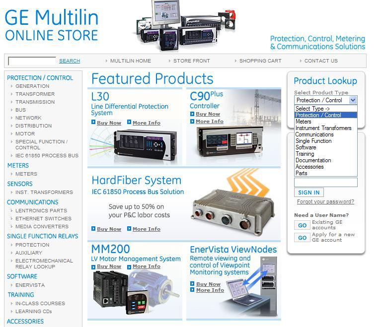
3 Introductions Tools Outline Enervista Launchpad On Line Store Demo Relays at Levine ANSI number Training CD s Protection Fundamentals 3
4 Objective We are here to help make your job easier. This is very informal and designed around Applications. Please ask question. We are not here to preach to you. The knowledge base in the room varies greatly. If you have a question, there is a good chance there are 3 or 4 other people that have the same question. Please ask it. 4
5 Tools 5
6 6

7 Demo Relays at L-3 7
8 Relays at L-3 8
9 9

10 GE Training CD s 10

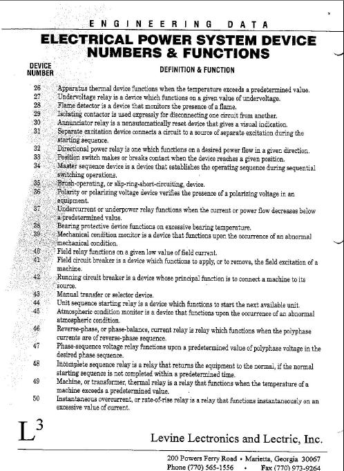
11 ANSI Symbols 11
12 Conversion of Electro-Mechanical to Electronic sheet 12
13 PowerPoint presentations at: 13
14 Protection Fundamentals 14
15 Desirable Protection Attributes Reliability: System operate properly Security: Don t trip when you shouldn t Dependability: Trip when you should Selectivity: Trip the minimal amount to clear the fault or abnormal operating condition Speed: Usually the faster the better in terms of minimizing equipment damage and maintaining system integrity Simplicity: KISS Economics: Don t break the bank 15
16 Art & Science of Protection Selection of protective relays requires compromises: Maximum and Reliable protection at minimum equipment cost High Sensitivity to faults and insensitivity to maximum load currents High-speed fault clearance with correct selectivity Selectivity in isolating small faulty area Ability to operate correctly under all predictable power system conditions 16
17 Art & Science of Protection Cost of protective relays should be balanced against risks involved if protection is not sufficient and not enough redundancy. Primary objectives is to have faulted zone s primary protection operate first, but if there are protective relays failures, some form of backup protection is provided. Backup protection is local (if local primary protection fails to clear fault) and remote (if remote protection fails to operate to clear fault) 17
18 Primary Equipment & Components Transformers - to step up or step down voltage level Breakers - to energize equipment and interrupt fault current to isolate faulted equipment Insulators - to insulate equipment from ground and other phases Isolators (switches) - to create a visible and permanent isolation of primary equipment for maintenance purposes and route power flow over certain buses. Bus - to allow multiple connections (feeders) to the same source of power (transformer). 18
19 Primary Equipment & Components Grounding - to operate and maintain equipment safely Arrester - to protect primary equipment of sudden overvoltage (lightning strike). Switchgear integrated components to switch, protect, meter and control power flow Reactors - to limit fault current (series) or compensate for charge current (shunt) VT and CT - to measure primary current and voltage and supply scaled down values to P&C, metering, SCADA, etc. Regulators - voltage, current, VAR, phase angle, etc. 19
20 Types of Protection Overcurrent Uses current to determine magnitude of fault Simple May employ definite time or inverse time curves May be slow Selectivity at the cost of speed (coordination stacks) Inexpensive May use various polarizing voltages or ground current for directionality Communication aided schemes make more selective 20
21 Instantaneous Overcurrent Protection (IOC) & Definite Time Overcurrent t CTI Relay closest to fault operates first Relays closer to source operate slower Time between operating for same current is called CTI (Clearing Time Interval) I CTI Distribution Substation 21
22 (TOC) Coordination t Relay closest to fault operates first Relays closer to source operate slower Time between operating for same current is called CTI I CTI Distribution Substation 22

23 Time Overcurrent Protection (TOC) Selection of the curves uses what is termed as a time multiplier or time dial to effectively shift the curve up or down on the time axis Operate region lies above selected curve, while no-operate region lies below it Inverse curves can approximate fuse curve shapes 23
 Multiples of pick-up")
24 Time Overcurrent Protection (51, 51N, 51G) Multiples of pick-up 24
25 Differential Types of Protection current in = current out Simple Very fast Very defined clearing area Expensive Practical distance limitations Line differential systems overcome this using digital communications 26
26 Current, pu 1 pu Differential I P CT-X CT-Y I P I S +1 I R-X Relay I R-Y I S 1 + (-1) = 0 Note CT polarity dots This is a through-current representation 0-1 Perfect waveforms, no saturation DIFF CURRENT 27
27 Current, pu I P 2 pu 2 pu Fault CT-X CT-Y I P Differential X I S I R-X Relay DIFF CURRENT I R-Y I S 2 + (+2) = 4 Note CT polarity dots This is an internal fault representation Perfect waveforms, no saturation 28
28 Types of Protection Voltage Uses voltage to infer fault or abnormal condition May employ definite time or inverse time curves May also be used for undervoltage load shedding Simple May be slow Selectivity at the cost of speed (coordination stacks) Inexpensive 29
29 Types of Protection Frequency Uses frequency of voltage to detect power balance condition May employ definite time or inverse time curves Used for load shedding & machinery under/overspeed protection Simple May be slow Selectivity at the cost of speed can be expensive 30
30 Types of Protection Power Uses voltage and current to determine power flow magnitude and direction Typically definite time Complex May be slow Accuracy important for many applications Can be expensive 31
31 Types of Protection Distance (Impedance) Uses voltage and current to determine impedance of fault Set on impedance [R-X] plane Uses definite time Impedance related to distance from relay Complicated Fast Somewhat defined clearing area with reasonable accuracy Expensive Communication aided schemes make more selective 32
32 X Z L Impedance Relay in Zone 1 operates first Time between Zones is called CTI R T 2 Z B T 1 Z A A B Source 33

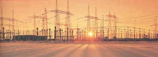
33 Generation-typically at 4-20kV Transmission-typically at kV Typical Bulk Power System Receives power from transmission system and transforms into subtransmission level Subtransmission-typically at kV Receives power from subtransmission system and transforms into primary feeder voltage Distribution network-typically kV Low voltage (service)-typically V 36
34 Protection Zones 1. Generator or Generator-Transformer Units 2. Transformers 3. Buses 4. Lines (transmission and distribution) 5. Utilization equipment (motors, static loads, etc.) 6. Capacitor or reactor (when separately protected) Unit Generator-Tx zone Transformer zone Bus zone Line zone Bus zone Transformer zone Bus zone Motor zone ~ Generator XFMR Bus Line Bus XFMR Bus Motor 37
 are opened.")
35 Zone Overlap 1. Overlap is accomplished by the locations of CTs, the key source for protective relays. 2. In some cases a fault might involve a CT or a circuit breaker itself, which means it can not be cleared until adjacent breakers (local or remote) are opened. Relay Zone A Relay Zone A Zone A Relay Zone B Zone B Zone A Relay Zone B Zone B CTs are located at both sides of CBfault between CTs is cleared from both remote sides CTs are located at one side of CBfault between CTs is sensed by both relays, remote right side operate only. 38
36 What Info is Required to Apply Protection 1. One-line diagram of the system or area involved 2. Impedances and connections of power equipment, system frequency, voltage level and phase sequence 3. Existing schemes 4. Operating procedures and practices affecting protection 5. Importance of protection required and maximum allowed clearance times 6. System fault studies 7. Maximum load and system swing limits 8. CTs and VTs locations, connections and ratios 9. Future expansion expectance 10. Any special considerations for application. 43

37 C37.2: Device Numbers Partial listing 44
38 One Line Diagram Non-dimensioned diagram showing how pieces of electrical equipment are connected Simplification of actual system Equipment is shown as boxes, circles and other simple graphic symbols Symbols should follow ANSI or IEC conventions 45
39 1-Line Symbols [1] 46
40 1-Line Symbols [2] 47
41 1-Line Symbols [3] 48
42 1-Line Symbols [4] 49
43 1-Line [1] 50
44 1-Line [2]
45 3-Line 52
46 CB Trip Circuit (Simplified) 55
47 Lock Out Relay PR 86b 86 TC 86a 86b Shown in RESET position 58
48 CB Coil Circuit Monitoring: T with CB Closed; C with CB Opened + Trip/Close Contact Coil Monitor Input 52/a or 52/b T/C Coil - Relay Breaker 52/a for trip circuit 52/b for close circuit 59
49 CB Coil Circuit Monitoring: Both T&C Regardless of CB state Relay Relay Breaker Breaker 60


50 Current Transformers Current transformers are used to step primary system currents to values usable by relays, meters, SCADA, transducers, etc. CT ratios are expressed as primary to secondary; 2000:5, 1200:5, 600:5, 300:5 A 2000:5 CT has a CTR of
51 Standard IEEE CT Relay Accuracy IEEE relay class is defined in terms of the voltage a CT can deliver at 20 times the nominal current rating without exceeding a 10% composite ratio error. For example, a relay class of C100 on a 1200:5 CT means that the CT can develop 100 volts at 24,000 primary amps (1200*20) without exceeding a 10% ratio error. Maximum burden = 1 ohm. 100 V = 20 * 5 * (1ohm) 200 V = 20 * 5 * (2 ohms) 400 V = 20 * 5 * (4 ohms) 800 V = 20 * 5 * (8 ohms) 62
52 Standard IEEE CT Burdens (5 Amp) (Per IEEE Std. C ) Application Burden Designation Impedance (Ohms) 5 amps Power Factor Metering B B B B B Relaying B B B B


53 Voltage Transformers Voltage (potential) transformers are used to isolate and step down and accurately reproduce the scaled voltage for the protective device or relay VT ratios are typically expressed as primary to secondary; 14400:120, 7200:120 A 4160:120 VT has a VTR of VP VS Relay 66
54 Typical CT/VT Circuits Courtesy of Blackburn, Protective Relay: Principles and Applications 67
55 CT/VT Circuit vs. Casing Ground Case Secondary Circuit Case ground made at IT location Secondary circuit ground made at first point of use 68
56 Equipment Grounding Prevents shock exposure of personnel Provides current carrying capability for the ground-fault current Grounding includes design and construction of substation ground mat and CT and VT safety grounding 69
57 System Grounding Limits overvoltages Limits difference in electric potential through local area conducting objects Several methods Ungrounded Reactance Coil Grounded High Z Grounded Low Z Grounded Solidly Grounded 70
58 System Grounding 1. Ungrounded: There is no intentional ground applied to the systemhowever it s grounded through natural capacitance. Found in kV systems. 2. Reactance Grounded: Total system capacitance is cancelled by equal inductance. This decreases the current at the fault and limits voltage across the arc at the fault to decrease damage. X 0 <= 10 * X 1 71
59 3. High Resistance Grounded: Limits ground fault current to 10A-20A. Used to limit transient overvoltages due to arcing ground faults. R 0 <= X 0C /3, X 0C is capacitive zero sequence reactance 4. Low Resistance Grounded: To limit current to A R 0 >= 2X 0 System Grounding 72
60 System Grounding 5. Solidly Grounded: There is a connection of transformer or generator neutral directly to station ground. Effectively Grounded: R 0 <= X 1, X 0 <= 3X 1, where R is the system fault resistance 73

61 Basic Current Connections: How System is Grounded Determines How Ground Fault is Detected Medium/High Resistance Ground Low/No Resistance Ground 79
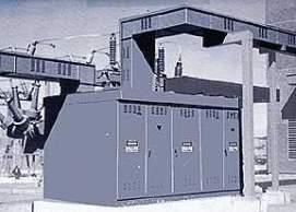
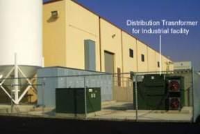
62 Substation Types Single Supply Multiple Supply Mobile Substations for emergencies Types are defined by number of transformers, buses, breakers to provide adequate service for application 80
63 Industrial Substation Arrangements (Typical) 81
64 Industrial Substation Arrangements (Typical) 82
65 Utility Substation Arrangements (Typical) Single Bus, 1 Tx, Dual supply Single Bus, 2 Tx, Dual Supply 2-sections Bus with HS Tie-Breaker, 2 Tx, Dual Supply 83
66 Utility Substation Arrangements (Typical) Bus 1 Bus 2 Breaker-and-a-half allows reduction of equipment cost by using 3 breakers for each 2 circuits. For load transfer and operation is simple, but relaying is complex as middle breaker is responsible to both circuits Ring bus advantage that one breaker per circuit. Also each outgoing circuit (Tx) has 2 sources of supply. Any breaker can be taken from service without disrupting others. 84
67 Tie breaker Utility Substation Arrangements (Typical) Main bus Aux. bus Main Reserve Transfer Bus 1 Bus 2 Double Bus: Upper Main and Transfer, bottom Double Main bus Main-Reserved and Transfer Bus: Allows maintenance of any bus and any breaker 85
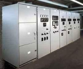
68 Switchgear Defined Assemblies containing electrical switching, protection, metering and management devices Used in three-phase, high-power industrial, commercial and utility applications Covers a variety of actual uses, including motor control, distribution panels and outdoor switchyards The term "switchgear" is plural, even when referring to a single switchgear assembly (never say, "switchgears") May be a described in terms of use: "the generator switchgear" "the stamping line switchgear" 86
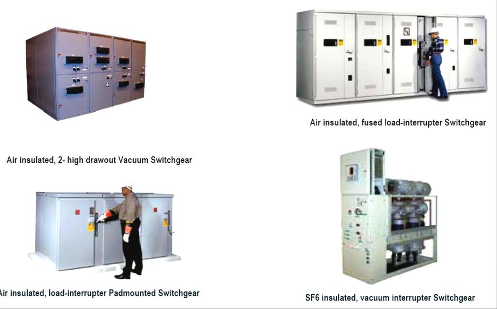
69 Switchgear Examples
70 A Good Day in System Protection CTs and VTs bring electrical info to relays Relays sense current and voltage and declare fault Relays send signals through control circuits to circuit breakers Circuit breaker(s) correctly trip What Could Go Wrong Here???? 94
71 A Bad Day in System Protection CTs or VTs are shorted, opened, or their wiring is Relays do not declare fault due to setting errors, faulty relay, CT saturation Control wires cut or batteries dead so no signal is sent from relay to circuit breaker Circuit breakers do not have power, burnt trip coil or otherwise fail to trip Protection Systems Typically are Designed for N-1 95
72 Protection Performance Statistics Correct and desired: 92.2% Correct but undesired: 5.3% Incorrect: 2.1% Fail to trip: 0.4% 96
73 Contribution to Faults 97
74 Fault Types (Shunt) 98
75 AC & DC Current Components of Fault Current 102
76 Useful Conversions 105
77 Per Unit System Establish two base quantities: Standard practice is to define Base power 3 phase Base voltage line to line Other quantities derived with basic power equations 106
78 Per Unit Basics 107
79 Short Circuit Calculations Per Unit System Per Unit Value = Actual Quantity Base Quantity V pu = V actual V base I pu = I actual I base Z pu = Z actual Z base 108
80 Short Circuit Calculations Per Unit System I base = MVA base x x kv L-L base Z base = kv2 L-L base MVA base 109
81 Short Circuit Calculations Per Unit System Base Conversion Z pu = Z actual Z base Z base = kv 2 base MVA base Z pu1 = MVA base1 kv 2 base1 X Z actual Z pu2 = MVA base2 kv 2 base2 X Z actual Z pu2 =Z pu1 x kv 2 base1 x MVA base2 kv 2 base2 MVA base1 110
82 A Study of a Fault. 123

83 Arc Flash Hazard 125
84 Protective Relaying Methods of Reducing Arc Flash Hazard Bus differential protection (this reduces the arc flash energy by reducing the clearing time Zone interlock schemes where bus relay selectively is allowed to trip or block depending on location of faults as identified from feeder relays Temporary setting changes to reduce clearing time during maintenance Sacrifices coordination FlexCurve for improved coordination opportunities Employ 51VC/VR on feeders fed from small generation to improve sensitivity and coordination Employ UV light detectors with current disturbance detectors for selective gear tripping 129

85 Arc Flash Hazards 131

86 Arc Pressure Wave 132
87 Copy of this presentation are at: 136
88 Protection Fundamentals QUESTIONS? 137
A DUMMIES GUIDE TO GROUND FAULT PROTECTION
 A DUMMIES GUIDE TO GROUND FAULT PROTECTION A DUMMIES GUIDE TO GROUND FAULT PROTECTION What is Grounding? The term grounding is commonly used in the electrical industry to mean both equipment grounding
NERC Protection Coordination Webinar Series June 9, Phil Tatro Jon Gardell
 Power Plant and Transmission System Protection Coordination GSU Phase Overcurrent (51T), GSU Ground Overcurrent (51TG), and Breaker Failure (50BF) Protection NERC Protection Coordination Webinar Series
Reducing the Effects of Short Circuit Faults on Sensitive Loads in Distribution Systems
 Reducing the Effects of Short Circuit Faults on Sensitive Loads in Distribution Systems Alexander Apostolov AREVA T&D Automation I. INTRODUCTION The electric utilities industry is going through significant
Busbars and lines are important elements
 CHAPTER CHAPTER 23 Protection of Busbars and Lines 23.1 Busbar Protection 23.2 Protection of Lines 23.3 Time-Graded Overcurrent Protection 23.4 Differential Pilot-Wire Protection 23.5 Distance Protection
Upgrading Your Electrical Distribution System To Resistance Grounding
 Upgrading Your Electrical Distribution System To Resistance Grounding The term grounding is commonly used in the electrical industry to mean both equipment grounding and system grounding. Equipment grounding
Numbering System for Protective Devices, Control and Indication Devices for Power Systems
 Appendix C Numbering System for Protective Devices, Control and Indication Devices for Power Systems C.1 APPLICATION OF PROTECTIVE RELAYS, CONTROL AND ALARM DEVICES FOR POWER SYSTEM CIRCUITS The requirements
Protection of Electrical Networks. Christophe Prévé
 Protection of Electrical Networks Christophe Prévé This Page Intentionally Left Blank Protection of Electrical Networks This Page Intentionally Left Blank Protection of Electrical Networks Christophe Prévé
PJM Manual 07:: PJM Protection Standards Revision: 2 Effective Date: July 1, 2016
 PJM Manual 07:: PJM Protection Standards Revision: 2 Effective Date: July 1, 2016 Prepared by System Planning Division Transmission Planning Department PJM 2016 Table of Contents Table of Contents Approval...6
COPYRIGHTED MATERIAL. Index
 Index Note: Bold italic type refers to entries in the Table of Contents, refers to a Standard Title and Reference number and # refers to a specific standard within the buff book 91, 40, 48* 100, 8, 22*,
ARC FLASH PPE GUIDELINES FOR INDUSTRIAL POWER SYSTEMS
 The Electrical Power Engineers Qual-Tech Engineers, Inc. 201 Johnson Road Building #1 Suite 203 Houston, PA 15342-1300 Phone 724-873-9275 Fax 724-873-8910 www.qualtecheng.com ARC FLASH PPE GUIDELINES FOR
UPGRADING SUBSTATION RELAYS TO DIGITAL RECLOSERS AND THEIR COORDINATION WITH SECTIONALIZERS
 UPGRADING SUBSTATION RELAYS TO DIGITAL RECLOSERS AND THEIR COORDINATION WITH SECTIONALIZERS 1 B. RAMESH, 2 K. P. VITTAL Student Member, IEEE, EEE Department, National Institute of Technology Karnataka,
Modern transformer relays include a comprehensive set of protective elements to protect transformers from faults and abnormal operating conditions
 1 Transmission transformers are important links in the bulk power system. They allow transfer of power from generation centers, up to the high-voltage grid, and to bulk electric substations for distribution
System Protection and Control Subcommittee
 Power Plant and Transmission System Protection Coordination Reverse Power (32), Negative Sequence Current (46), Inadvertent Energizing (50/27), Stator Ground Fault (59GN/27TH), Generator Differential (87G),
ARC FLASH HAZARD ANALYSIS AND MITIGATION
 ARC FLASH HAZARD ANALYSIS AND MITIGATION J.C. Das IEEE PRESS SERIES 0N POWER ENGINEERING Mohamed E. El-Hawary, Series Editor IEEE IEEE PRESS WILEY A JOHN WILEY & SONS, INC., PUBLICATION CONTENTS Foreword
Electrical Protection System Design and Operation
 ELEC9713 Industrial and Commercial Power Systems Electrical Protection System Design and Operation 1. Function of Electrical Protection Systems The three primary aims of overcurrent electrical protection
Transmission Line Protection Objective. General knowledge and familiarity with transmission protection schemes
 Transmission Line Protection Objective General knowledge and familiarity with transmission protection schemes Transmission Line Protection Topics Primary/backup protection Coordination Communication-based
1 INTRODUCTION 1.1 PRODUCT DESCRIPTION
 GEK-00682D INTRODUCTION INTRODUCTION. PRODUCT DESCRIPTION The MDP Digital Time Overcurrent Relay is a digital, microprocessor based, nondirectional overcurrent relay that protects against phase-to-phase
Transmission Protection Overview
 Transmission Protection Overview 2017 Hands-On Relay School Daniel Henriod Schweitzer Engineering Laboratories Pullman, WA Transmission Line Protection Objective General knowledge and familiarity with
NERC Protection Coordination Webinar Series June 16, Phil Tatro Jon Gardell
 Power Plant and Transmission System Protection Coordination Phase Distance (21) and Voltage-Controlled or Voltage-Restrained Overcurrent Protection (51V) NERC Protection Coordination Webinar Series June
Sequence Networks p. 26 Sequence Network Connections and Voltages p. 27 Network Connections for Fault and General Unbalances p. 28 Sequence Network
 Preface p. iii Introduction and General Philosophies p. 1 Introduction p. 1 Classification of Relays p. 1 Analog/Digital/Numerical p. 2 Protective Relaying Systems and Their Design p. 2 Design Criteria
Bus Protection Fundamentals
 Bus Protection Fundamentals Terrence Smith GE Grid Solutions 2017 Texas A&M Protective Relay Conference Bus Protection Requirements High bus fault currents due to large number of circuits connected: CT
COPYRIGHTED MATERIAL. Introduction to protective relaying. 1.1 What is relaying?
 1 Introduction to protective relaying 1.1 What is relaying? In order to understand the function of protective relaying systems, one must be familiar with the nature and the modes of operation of an electric
Webinar: An Effective Arc Flash Safety Program
 Webinar: An Effective Arc Flash Safety Program Daleep Mohla September 10 th, 2015: 2pm ET Agenda Arc Flash Defined and Quantified NFPA 70E / CSA Z 462 - Recent Updates What is the ANSI Z10 Hierarchy of
Unit 3 Magnetism...21 Introduction The Natural Magnet Magnetic Polarities Magnetic Compass...21
 Chapter 1 Electrical Fundamentals Unit 1 Matter...3 Introduction...3 1.1 Matter...3 1.2 Atomic Theory...3 1.3 Law of Electrical Charges...4 1.4 Law of Atomic Charges...4 Negative Atomic Charge...4 Positive
Preface...x Chapter 1 Electrical Fundamentals
 Preface...x Chapter 1 Electrical Fundamentals Unit 1 Matter...3 Introduction...3 1.1 Matter...3 1.2 Atomic Theory...3 1.3 Law of Electrical Charges...4 1.4 Law of Atomic Charges...5 Negative Atomic Charge...5
Notes 1: Introduction to Distribution Systems
 Notes 1: Introduction to Distribution Systems 1.0 Introduction Power systems are comprised of 3 basic electrical subsystems. Generation subsystem Transmission subsystem Distribution subsystem The subtransmission
Distribution Feeder Principles
 Distribution Feeder Principles Distribution Feeder Principles Introduction Electrical distribution is the final stage in the delivery of electricity to end users. The distribution system s network carries
A Tutorial on the Application and Setting of Collector Feeder Overcurrent Relays at Wind Electric Plants
 A Tutorial on the Application and Setting of Collector Feeder Overcurrent Relays at Wind Electric Plants Martin Best and Stephanie Mercer, UC Synergetic, LLC Abstract Wind generating plants employ several
Power systems Protection course
 Al-Balqa Applied University Power systems Protection course Department of Electrical Energy Engineering 1 Part 5 Relays 2 3 Relay Is a device which receive a signal from the power system thought CT and
Grounding for Power Quality
 Presents Grounding for Power Quality Grounding for Power Quality NEC 250.53 states that ground resistance should be less than 25 ohms. Is this true? Grounding for Power Quality No! NEC 250.53 states
Protection Introduction
 1.0 Introduction Protection 2 There are five basic classes of protective relays: Magnitude relays Directional relays Ratio (impedance) relays Differential relays Pilot relays We will study each of these.
Back to the Basics Current Transformer (CT) Testing
 Testing") Back to the Basics Current Transformer (CT) Testing As test equipment becomes more sophisticated with better features and accuracy, we risk turning our field personnel into test set operators instead of
Back to the Basics Current Transformer (CT) Testing As test equipment becomes more sophisticated with better features and accuracy, we risk turning our field personnel into test set operators instead of
3. (a) List out the advantages and disadvantages of HRC fuse (b) Explain fuse Characteristics in detail. [8+8]
![3. (a) List out the advantages and disadvantages of HRC fuse (b) Explain fuse Characteristics in detail. [8+8]](/thumbs/77/76027701.jpg "3. (a) List out the advantages and disadvantages of HRC fuse (b) Explain fuse Characteristics in detail. [8+8]") Code No: RR320205 Set No. 1 1. (a) Explain about Bewley s Lattice diagrams and also mention the uses of these diagrams. [6+2] (b) A line of surge impedance of 400 ohms is charged from a battery of constant
Code No: RR320205 Set No. 1 1. (a) Explain about Bewley s Lattice diagrams and also mention the uses of these diagrams. [6+2] (b) A line of surge impedance of 400 ohms is charged from a battery of constant
GENERATOR INTERCONNECTION APPLICATION Category 5 For All Projects with Aggregate Generator Output of More Than 2 MW
 GENERATOR INTERCONNECTION APPLICATION Category 5 For All Projects with Aggregate Generator Output of More Than 2 MW ELECTRIC UTILITY CONTACT INFORMATION Consumers Energy Interconnection Coordinator 1945
ANALYSIS OF A FLASHOVER OPERATION ON TWO 138KV TRANSMISSION LINES
 ANALYSIS OF A FLASHOVER OPERATION ON TWO 138KV TRANSMISSION LINES Authors: Joe Perez, P.E.: SynchroGrid, College Station, Texas Hung Ming Chou, SynchroGrid, College Station, Texas Mike McMillan, Bryan
Using a Multiple Analog Input Distance Relay as a DFR
 Using a Multiple Analog Input Distance Relay as a DFR Dennis Denison Senior Transmission Specialist Entergy Rich Hunt, M.S., P.E. Senior Field Application Engineer NxtPhase T&D Corporation Presented at
A short introduction to Protection and Automation Philosophy
 Training Center A short introduction to Protection and Automation Philosophy Philippe Goossens & Cédric Moors Training Center Contents Definitions and basic concepts Differential and distance protection
TABLE OF CONTENT
 Page : 1 of 34 Project Engineering Standard www.klmtechgroup.com KLM Technology #03-12 Block Aronia, Jalan Sri Perkasa 2 Taman Tampoi Utama 81200 Johor Bahru Malaysia TABLE OF CONTENT SCOPE 3 REFERENCES
Lightning test in lab. Symmetrical fault and protection. Olof Samuelsson
 Lightning test in lab Symmetrical fault and protection Olof Samuelsson Outline Three-phase short-circuit fault current Network representation Circuit breakers and disconnectors Measurement transformers
TECHNICAL BULLETIN 004a Ferroresonance
 May 29, 2002 TECHNICAL BULLETIN 004a Ferroresonance Abstract - This paper describes the phenomenon of ferroresonance, the conditions under which it may appear in electric power systems, and some techniques
How to maximize reliability using an alternative distribution system for critical loads
 White Paper WP024001EN How to maximize reliability using an alternative distribution system for critical loads Executive summary The electric power industry has several different distribution topologies
Power System Protection Manual
 Power System Protection Manual Note: This manual is in the formative stage. Not all the experiments have been covered here though they are operational in the laboratory. When the full manual is ready,
NERC Protection Coordination Webinar Series July 15, Jon Gardell
 Power Plant and Transmission System Protection Coordination Reverse Power (32), Negative Sequence Current (46), Inadvertent Energizing (50/27), Stator Ground Fault (59GN/27TH), Generator Differential (87G),
PIPSPC. Prepared by Eng: Ahmed Safie Eldin. And. Introduction. Protection Control. Practical. System. Power
 PIPSPC Practical Introduction Power System Protection Control Practical Introduction To Power System Protection And Control Prepared by Eng: Ahmed Safie Eldin 2005 Contents POWER SYSTEMS PRINCIPALS. 1
POWER SYSTEM PRINCIPLES APPLIED IN PROTECTION PRACTICE. Professor Akhtar Kalam Victoria University
 POWER SYSTEM PRINCIPLES APPLIED IN PROTECTION PRACTICE Professor Akhtar Kalam Victoria University The Problem Calculate & sketch the ZPS, NPS & PPS impedance networks. Calculate feeder faults. Calculate
Utility Interconnection and System Protection
 Utility Interconnection and System Protection Alex Steselboim President, Advanced Power Technologies, Inc. Utility paralleling vs. isolated operation. Isochronous kw load sharing Reactive power (VAR) sharing
Tab 2 Voltage Stresses Switching Transients
 Tab 2 Voltage Stresses Switching Transients Distribution System Engineering Course Unit 10 2017 Industry, Inc. All rights reserved. Transient Overvoltages Decay with time, usually within one or two cycles
10. DISTURBANCE VOLTAGE WITHSTAND CAPABILITY
 9. INTRODUCTION Control Cabling The protection and control equipment in power plants and substations is influenced by various of environmental conditions. One of the most significant environmental factor
Protective Relays Digitrip 3000
 New Information Technical Data Effective: May 1999 Page 1 Applications Provides reliable 3-phase and ground overcurrent protection for all voltage levels. Primary feeder circuit protection Primary transformer
SUBJECT CODE : EE6702 SUBJECT NAME: Protection & switchgear STAFF NAME : Ms.J.C.Vinitha
 SUBJECT CODE : EE6702 SUBJECT NAME: Protection & switchgear STAFF NAME : Ms.J.C.Vinitha EE2402 - PROTECTION & SWITCHGEAR SYLLABUS ELECTRIC POWER SYSTEM Electricity is generated at a power plant (1), voltage
Course No: 1 13 (3 Days) FAULT CURRENT CALCULATION & RELAY SETTING & RELAY CO-ORDINATION. Course Content
 FAULT CURRENT CALCULATION & RELAY SETTING & RELAY CO-ORDINATION. Course Content") Course No: 1 13 (3 Days) FAULT CURRENT CALCULATION & RELAY SETTING & RELAY CO-ORDINATION Sr. No. Course Content 1.0 Fault Current Calculations 1.1 Introduction to per unit and percentage impedance 1.2
Course No: 1 13 (3 Days) FAULT CURRENT CALCULATION & RELAY SETTING & RELAY CO-ORDINATION Sr. No. Course Content 1.0 Fault Current Calculations 1.1 Introduction to per unit and percentage impedance 1.2
Transformer Protection
 Transformer Protection Transformer Protection Outline Fuses Protection Example Overcurrent Protection Differential Relaying Current Matching Phase Shift Compensation Tap Changing Under Load Magnetizing
FERRORESONANCE SIMULATION STUDIES USING EMTP
 FERRORESONANCE SIMULATION STUDIES USING EMTP Jaya Bharati, R. S. Gorayan Department of Electrical Engineering Institute of Technology, BHU Varanasi, India jbharatiele@gmail.com, rsgorayan.eee@itbhu.ac.in
Safety through proper system Grounding and Ground Fault Protection
 Safety through proper system Grounding and Ground Fault Protection November 4 th, 2015 Presenter: Mr. John Nelson, PE, FIEEE, NEI Electric Power Engineering, Inc. Event to start shortly Scheduled time:
BE1-67N GROUND DIRECTIONAL OVERCURRENT RELAY FEATURES ADDITIONAL INFORMATION. FUNCTIONS AND FEATURES Pages 2-4. APPLICATIONS Page 2
 BE1-67N GROUND DIRECTIONAL OVERCURRENT RELAY The BE1-67N Ground Directional Overcurrent Relay provides ground fault protection for transmission and distribution lines by sensing the direction and magnitude
thepower to protect the power to protect i-gard LITERATURE Low and medium voltage
 thepower to protect i-gard LITERATURE Low and medium voltage distribution systems Arc Flash Hazards and High Resistance Grounding Grounding of Standby and Emergency Power Systems Neutral Grounding Resistors
OPERATING, METERING AND EQUIPMENT PROTECTION REQUIREMENTS FOR PARALLEL OPERATION OF LARGE-SIZE GENERATING FACILITIES GREATER THAN 25,000 KILOWATTS
 OPERATING, METERING AND EQUIPMENT PROTECTION REQUIREMENTS FOR PARALLEL OPERATION OF LARGE-SIZE GENERATING FACILITIES GREATER THAN 25,000 KILOWATTS AND MEDIUM-SIZE FACILITIES (5,000-25,000KW) CONNECTED
Time-current Coordination
 269 5.2.3.1 Time-current Coordination Time that is controlled by current magnitude permits discriminating faults at one location from another. There are three variables available to discriminate faults,
Comparison of recloser and breaker standards
 s Technical Data TD280024EN Supersedes February 1994 (R280-90-5) COOPER POWER SERIES Comparison of recloser and breaker standards Technical Data TD280024EN Comparison of recloser and breaker standards
EH2741 Communication and Control in Electric Power Systems Lecture 2
 KTH ROYAL INSTITUTE OF TECHNOLOGY EH2741 Communication and Control in Electric Power Systems Lecture 2 Lars Nordström larsno@kth.se Course map Outline Transmission Grids vs Distribution grids Primary Equipment
PRC Generator Relay Loadability. Guidelines and Technical Basis Draft 5: (August 2, 2013) Page 1 of 76
 Page 1 of 76") PRC-025-1 Introduction The document, Power Plant and Transmission System Protection Coordination, published by the NERC System Protection and Control Subcommittee (SPCS) provides extensive general discussion
PRC-025-1 Introduction The document, Power Plant and Transmission System Protection Coordination, published by the NERC System Protection and Control Subcommittee (SPCS) provides extensive general discussion
Connection Impact Assessment Application
 Connection Impact Assessment Application This form is for generators applying for Connection Impact Assessment (CIA) and for generators with a project size >10 kw. Please return the completed form by email,
Protective Relaying for DER
 Protective Relaying for DER Rogerio Scharlach Schweitzer Engineering Laboratories, Inc. Basking Ridge, NJ Overview IEEE 1547 general requirements to be met at point of common coupling (PCC) Distributed
PRC Generator Relay Loadability. Guidelines and Technical Basis Draft 4: (June 10, 2013) Page 1 of 75
 Page 1 of 75") PRC-025-1 Introduction The document, Power Plant and Transmission System Protection Coordination, published by the NERC System Protection and Control Subcommittee (SPCS) provides extensive general discussion
PRC-025-1 Introduction The document, Power Plant and Transmission System Protection Coordination, published by the NERC System Protection and Control Subcommittee (SPCS) provides extensive general discussion
2. Current interruption transients
 1 2. Current interruption transients For circuit breakers or other switching facilities, transient voltages just after the current interruptions are of great concern with successful current breakings,
Generation Interconnection Requirements at Voltages 34.5 kv and Below
 Generation Interconnection Requirements at Voltages 34.5 kv and Below 2005 March GENERATION INTERCONNECTION REQUIREMENTS AT 34.5 KV AND BELOW PAGE 1 OF 36 TABLE OF CONTENTS 1. INTRODUCTION 5 1.1. Intent
Topic 6 Quiz, February 2017 Impedance and Fault Current Calculations For Radial Systems TLC ONLY!!!!! DUE DATE FOR TLC- February 14, 2017
 Topic 6 Quiz, February 2017 Impedance and Fault Current Calculations For Radial Systems TLC ONLY!!!!! DUE DATE FOR TLC- February 14, 2017 NAME: LOCATION: 1. The primitive self-inductance per foot of length
Transmission Lines and Feeders Protection Pilot wire differential relays (Device 87L) Distance protection
 Distance protection") Transmission Lines and Feeders Protection Pilot wire differential relays (Device 87L) Distance protection 133 1. Pilot wire differential relays (Device 87L) The pilot wire differential relay is a high-speed
Transmission Lines and Feeders Protection Pilot wire differential relays (Device 87L) Distance protection 133 1. Pilot wire differential relays (Device 87L) The pilot wire differential relay is a high-speed
POWER FACTOR CORRECTION. HARMONIC FILTERING. MEDIUM AND HIGH VOLTAGE SOLUTIONS.
 POWER FACTOR CORRECTION. HARMONIC FILTERING. MEDIUM AND HIGH VOLTAGE SOLUTIONS. This document may be subject to changes. Contact ARTECHE to confirm the characteristics and availability of the products
Power System Fundamentals
 Power System Fundamentals Relay Applications PJM State & Member Training Dept. Objectives At the end of this presentation the Student will be able to: Describe the purpose of protective relays Identify
Power Quality Basics. Presented by. Scott Peele PE
 Power Quality Basics Presented by Scott Peele PE PQ Basics Terms and Definitions Surge, Sag, Swell, Momentary, etc. Measurements Causes of Events Possible Mitigation PQ Tool Questions Power Quality Measurement
CHAPTER 5 POWER QUALITY IMPROVEMENT BY USING POWER ACTIVE FILTERS
 86 CHAPTER 5 POWER QUALITY IMPROVEMENT BY USING POWER ACTIVE FILTERS 5.1 POWER QUALITY IMPROVEMENT This chapter deals with the harmonic elimination in Power System by adopting various methods. Due to the
RAIDK, RAIDG, RAPDK and RACIK Phase overcurrent and earth-fault protection assemblies based on single phase measuring elements
 RAIDK, RAIDG, RAPDK and RACIK Phase overcurrent and earth-fault protection assemblies based on single phase measuring elements User s Guide General Most faults in power systems can be detected by applying
BED INTERCONNECTION TECHNICAL REQUIREMENTS
 BED INTERCONNECTION TECHNICAL REQUIREMENTS By Enis Šehović, P.E. 2/11/2016 Revised 5/19/2016 A. TABLE OF CONTENTS B. Interconnection Processes... 2 1. Vermont Public Service Board (PSB) Rule 5.500... 2
MODEL POWER SYSTEM TESTING GUIDE October 25, 2006
 October 25, 2006 Document name Category MODEL POWER SYSTEM TESTING GUIDE ( ) Regional Reliability Standard ( ) Regional Criteria ( ) Policy ( ) Guideline ( x ) Report or other ( ) Charter Document date
1% Switchgear and Substations
 1% Switchgear and Substations Switchgear and substations are not always matters of concern for transmitter designers, -because they are often part of the facilities of a typical installation. However,
Embedded Generation Connection Application Form
 Embedded Generation Connection Application Form This Application Form provides information required for an initial assessment of the Embedded Generation project. All applicable sections must be completed
OPEN-PHASE DETECTION TECHNIQUES FOR CRITICAL STANDBY SUPPLIES
 OPEN-PHASE DETECTION TECHNIQUES FOR CRITICAL STANDBY SUPPLIES U AJMAL, GE Grid Solutions UK Ltd, usman.ajmal@ge.com S SUBRAMANIAN, GE Grid Solutions UK Ltd, sankara.subramanian@ge.com H Ha GE Grid Solutions
Optimizing HV Capacitor-Bank Design Protection & Testing
 Optimizing HV Capacitor-Bank Design Protection & Testing Benton Vandiver III ABB Inc. 71st Annual Conference for Protective Relay Engineers Texas A&M University Introduction Shunt Capacitor Bank Considerations
NO WARRANTIES OF ANY KIND ARE IMPLIED ON THE INFORMATION CONTAINED IN THIS DOCUMENT.
 MODBUS/BECO2200-M3425A Communication Data Base for M-3425A Integrated Protection System Device I.D. = 150 Specifications presented herein are thought to be accurate at the time of publication but are subject
Section 11: Power Quality Considerations Bill Brown, P.E., Square D Engineering Services
 Section 11: Power Quality Considerations Bill Brown, P.E., Square D Engineering Services Introduction The term power quality may take on any one of several definitions. The strict definition of power quality
The Importance of the Neutral-Grounding Resistor. Presented by: Jeff Glenney, P.Eng. and Don Selkirk, E.I.T.
 The Importance of the Neutral-Grounding Resistor Presented by: Jeff Glenney, P.Eng. and Don Selkirk, E.I.T. Presentation Preview What is high-resistance grounding (HRG)? What is the purpose of HRG? Why
CHAPTER 2 ELECTRICAL POWER SYSTEM OVERCURRENTS
 CHAPTER 2 ELECTRICAL POWER SYSTEM OVERCURRENTS 2-1. General but less than locked-rotor amperes and flows only Electrical power systems must be designed to serve in the normal circuit path. a variety of
Overview of Grounding for Industrial and Commercial Power Systems Presented By Robert Schuerger, P.E.
 Overview of Grounding for Industrial and Commercial Power Systems Presented By Robert Schuerger, P.E. HP Critical Facility Services delivered by EYP MCF What is VOLTAGE? Difference of Electric Potential
Optimal neutral ground resistor rating of the medium voltage systems in power generating stations
 Journal of International Council on Electrical Engineering ISSN: (Print) 2234-8972 (Online) Journal homepage: http://www.tandfonline.com/loi/tjee20 Optimal neutral ground resistor rating of the medium
Power Plant and Transmission System Protection Coordination of-field (40) and Out-of. of-step Protection (78)
 and Out-of. of-step Protection (78)") Power Plant and Transmission System Protection Coordination Loss-of of-field (40) and Out-of of-step Protection (78) System Protection and Control Subcommittee Protection Coordination Workshop Phoenix,
Power Plant and Transmission System Protection Coordination Loss-of of-field (40) and Out-of of-step Protection (78) System Protection and Control Subcommittee Protection Coordination Workshop Phoenix,
Power Plant and Transmission System Protection Coordination Fundamentals
 Power Plant and Transmission System Protection Coordination Fundamentals NERC Protection Coordination Webinar Series June 2, 2010 Jon Gardell Agenda 2 Objective Introduction to Protection Generator and
Shortcomings of the Low impedance Restricted Earth Fault function as applied to an Auto Transformer. Anura Perera, Paul Keller
 Shortcomings of the Low impedance Restricted Earth Fault function as applied to an Auto Transformer Anura Perera, Paul Keller System Operator - Eskom Transmission Introduction During the design phase of
Impacts of the Renewable Energy Resources on the Power System Protection by: Brent M. Fedele, P.E., National Grid for: 11 th Annual CNY Engineering
 Impacts of the Renewable Energy Resources on the Power System Protection by: Brent M. Fedele, P.E., National Grid for: 11 th Annual CNY Engineering Expo - Nov. 3, 2014 Index Normal Distribution System
Generator Protection GENERATOR CONTROL AND PROTECTION
 Generator Protection Generator Protection Introduction Device Numbers Symmetrical Components Fault Current Behavior Generator Grounding Stator Phase Fault (87G) Field Ground Fault (64F) Stator Ground Fault
Arizona Public Service Company and the Transmission Partnership for National Electric Power Company of Jordan
 Arizona Public Service Company and the Transmission Partnership for National Electric Power Company of Jordan Mark Hackney October 5-8, 2009 Amman, Jordan Energy Control Center Layout 2 Energy Control
This webinar brought to you by The Relion Product Family Next Generation Protection and Control IEDs from ABB
 This webinar brought to you by The Relion Product Family Next Generation Protection and Control IEDs from ABB Relion. Thinking beyond the box. Designed to seamlessly consolidate functions, Relion relays
OPERATING, METERING, AND EQUIPMENT PROTECTION REQUIREMENTS FOR PARALLEL OPERATION OF LARGE-SIZE GENERATING FACILITIES GREATER THAN 2,000 KILOWATTS
 OPERATING, METERING, AND EQUIPMENT PROTECTION REQUIREMENTS FOR PARALLEL OPERATION OF LARGE-SIZE GENERATING FACILITIES GREATER THAN 2,000 KILOWATTS CONNECTED TO THE DISTRIBUTION SYSTEM ORANGE AND ROCKLAND
Embedded Generation Connection Application Form
 Embedded Generation Connection Application Form This Application Form provides information required for an initial assessment of the Embedded Generation project. All applicable sections must be completed
Impact Assessment Generator Form
 Impact Assessment Generator Form This connection impact assessment form provides information for the Connection Assessment and Connection Cost Estimate. Date: (dd/mm/yyyy) Consultant/Developer Name: Project
2 Grounding of power supply system neutral
 2 Grounding of power supply system neutral 2.1 Introduction As we had seen in the previous chapter, grounding of supply system neutral fulfills two important functions. 1. It provides a reference for the
Appendix C-1. Protection Requirements & Guidelines Non-Utility Generator Connection to Okanogan PUD
 A. Introduction Appendix C-1 Protection Requirements & Guidelines to Okanogan PUD The protection requirements identified in this document apply to Non-Utility Generating (NUG) facilities, Independent Power
EE 741 Spring Electric Power Distribution Systems An Overview
 EE 741 Spring 2017 Electric Power Distribution Systems An Overview Basic Power System Layout There are over 100 substations in the Las Vegas Valley pic of closest substation Substation Design Substation
Transmission System Phase Backup Protection
 Reliability Guideline Transmission System Phase Backup Protection NERC System Protection and Control Subcommittee Draft for Planning Committee Approval June 2011 Table of Contents 1. Introduction and Need
Embedded Generation Connection Application Form
 Embedded Generation Connection Application Form This Application Form provides information required for an initial assessment of the Embedded Generation project. All applicable sections must be completed