LED Modifications. Below are directions on how I modify LED strings for repairs, upgrade to full wave rectification, or custom lengths/number of LEDs.
|
|
|
- Johnathan Alexander
- 5 years ago
- Views:
Transcription
1 LED Modifications Below are directions on how I modify LED strings for repairs, upgrade to full wave rectification, or custom lengths/number of LEDs. Caution! Working with electricity and modifying electrical components is dangerous. Do this at your own risk and always utilize safety first! LED Calculations Example Schematic Building the Strings Results LED Calculations 1. Peek Voltage - Peek voltage out of the full wave rectifier from 120VAC RMS equals 170V minus the voltage dropped by the diodes. This would result in about 167V. a. Rounded voltages, 120VAC *1.414 = 170V. b. 170V - 2.8V = 167V 2. LED Voltage and Current a. Voltage varies by manufacturer and color for LEDs. The most common current is near 20mA. You must look up the specifications for your LED string. b. In my examples below, I ll be using: Red = 2.0V, 17mA or 0.017A 3. Resistor Calculation (Example using a shortened string of 26 Red LEDs.) a. Calculate voltage drop of LEDs i. 2.0V x 26 = 52V b. Calculate peek voltage minus voltage dropped by the LEDs i. 167V 52V = 115V c. Calculate Resistor(s) needed to drop remaining voltage i. Ohms - 115V / 0.017A = 6.764KOhm (Use next higher standard value, for example, 8.2KOhm) ii. Watts - 115V * 0.017A = 1.955Watt (Use a minimum of 2 watt resistor) 4. Rectification You will need 4 diodes per string to make the full wave rectifiers. a. I use 600V/1A diodes. Mouser part number 821-1N Here is a link to a handy online calculator which I use: Limitations: This example does not utilize any voltage doubling circuits. You are limited to using the number of LEDs that add up to or just below 167V. For example, I could build a string using a maximum of 83 Red LEDS which drop 2.0V each. This would utilize 166V of the available 167V. Other LED colors drop higher voltages. For long strings, you must divide the string in half and build full wave rectifiers for each section. Tip: When purchasing resistors, you can use one or more. Rather than just using the one 8.2KOhm resistor, you could use two resistors, one on each end that adds up to at least 6.8KOhms or just over that value. I d also recommend purchasing resistors in bulk where you can. I calculated the resistor sizes needed for each of my strings based on number or LEDs and voltage differences based on color. I then purchased resistors with a value common to all of my strings, but within the closest range of my

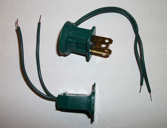
 above. 2. Cut off and retain the male and female plug ends.")
2 requirements. This allows me to use the same resistors for most strings, and I commonly only use two different resistor sizes. For example, I have purchased both 3.6KOhm/2watt and 2.7KOhm/2watt resistors for all of my strings. I may use one, two, or a combination of these values depending on my needs. Example Schematic Building the Strings Parts: 4 x 1N4005 diodes 2 x 3.6KOhm/2watt Resistors LED string shortened to 26 count 1. In my example, I am shortening a string of Red LEDS to only use 26 LEDs and still allow AC voltage pass through to the female plug end (J1) above. 2. Cut off and retain the male and female plug ends. Discard any existing rectifiers (blobs) that came with your strings. 3. Shorten the string to the number of LEDs you require. Note: this is dependant upon your need.


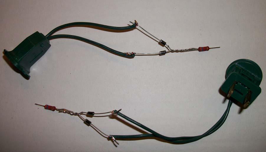
3 4. Assemble the male and female end rectifier components (2 x diodes, 1 x resistor for each end). Tin the ends and solder the diodes together and the resistor in place. Note: you can place the resistors at any location within the rectifier. When using two, I place one on each end of the circuit, this is just my preference. a. Reference the below image for proper orientation of the diodes in relation to the male and female ends as well as connection to LED strings. Also reference schematic above. 5. Solder the components to the male and female ends. Ensure you have the orientation of anode/cathode of the diodes correct. Note, if you plan to use heat shrink for the components, place the pieces as required before soldering to any wires. I use electrical tape. a. Diodes to AC power from male plug b. LED to resistor c. AC pass through wires to female end
4

5


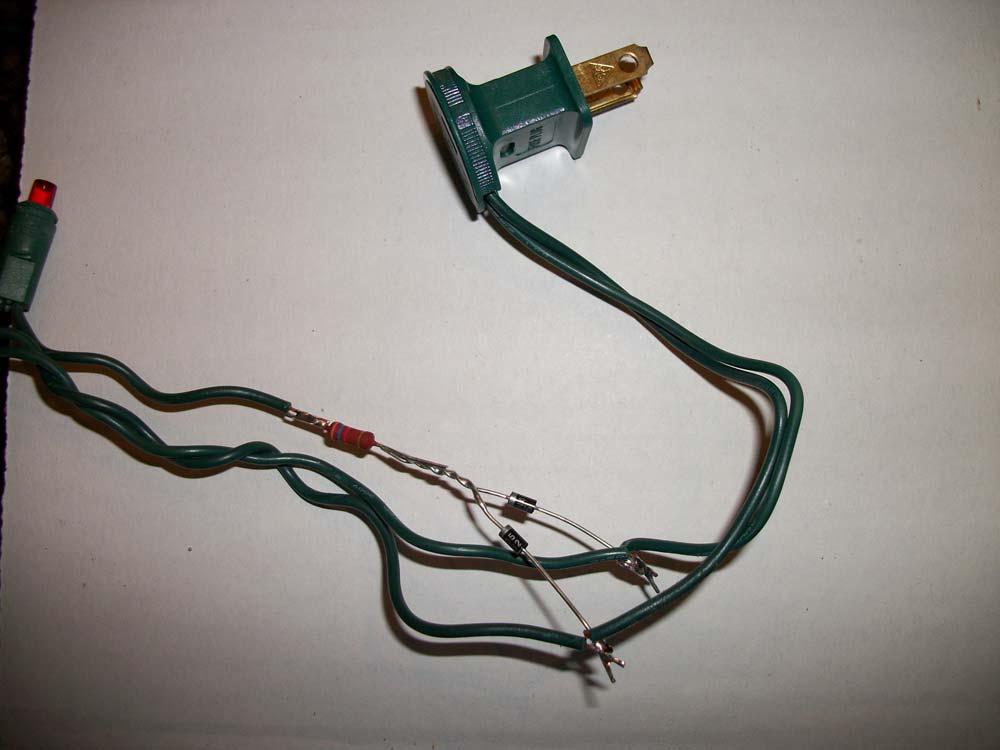
6 6. You must now wrap with tape or protect with heat shrink tubing, one leg of the diodes so that they don t short together. This is before they are joined as part of the bridge. See picture below. 7. Thoroughly protect any exposed components and wires with electrical tape if you are not using heat shrink.


7 8. Wrap the entire sections with electrical tape. Note: I have not had any issues only using electrical tape. Moisture is not a factor here, protection from exposed wires and heat from the resistors are my concerns. Results
Convert 10M (33 ) 100 LED Sequencing Strings to Full Wave Always On.
 100 LED Sequencing Strings to Full Wave Always On.") Convert 10M (33 ) 100 LED Sequencing Strings to Full Wave Always On. DoItYourselfChristmas.Com User: CaptKirk If you search EBAY, you will find a number of vendors offering 10m 100 LED Fairy Lights. That
Convert 10M (33 ) 100 LED Sequencing Strings to Full Wave Always On. DoItYourselfChristmas.Com User: CaptKirk If you search EBAY, you will find a number of vendors offering 10m 100 LED Fairy Lights. That
ICOM R10 Receiver Modification to Provide S-Meter Output
 ICOM R10 Receiver Modification to Provide S-Meter Output A Technical Application Note from Doppler Systems Inc. Acknowledgements April 21, 2001 Revised June 6, 2004 This application note was submitted
Line Following Circuit Board Wiring Guide
 Line Following Circuit Board Wiring Guide Soldering the Analog Optosensors 1. Obtain a line following printed circuit board from the store as well as three analog optosensors (w/6 resistors). 2. Remove
QUASAR ELECTRONICS KIT No DRILL SPEED CONTROLLER
 QUASAR ELECTRONICS KIT No. 1074 DRILL SPEED CONTROLLER General Description If you work with an electric drill and unless you are lucky enough to own one of the most sophisticated models with speed control,
Topic Rectification. Draw and understand the use of diodes in half wave and full wave
 Topic 2.4.2 Learning Objectives: At the end of this topic you will be able to; Draw and understand the use of diodes in half wave and full wave bridge rectifiers; Calculate the peak value of the output
AC/DC POWER SUPPLY KIT
 AC/DC POWER SUPPLY KIT MODEL K-11 Assembly and Instruction Manual ELENCO Copyright 2016, 1989 by ELENCO All rights reserved. Revised 2016 REV-O 753211 No part of this book shall be reproduced by any means;
SoftRock v5.0 Builder s Notes. December 12, Building a QSD Kit
 SoftRock v5.0 Builder s Notes December 12, 2005 Building a QSD Kit Be sure to use a grounded tip soldering iron in building the QSD board. The soldering iron needs to have a small tip, (0.05-0.1 inch diameter),
Lighthouse Beginner s soldering kit
 Lighthouse Beginner s soldering kit Kit contains: 1 x 220 ohm resistor (Red, Red, Black) 1 x 82k ohm resistor (Grey, Red, Orange) 2 x 220k ohm resistors (Red, Red, Yellow) 2 x Diodes 1 x Power switch 1
BRIDGE MODE FOR THE STEREO 120. Preface to Everything PLEASE READ THIS FIRST! YOU MAY SAVE YOURSELF A LOT OF TROUBLE!
 BRIDGE MODE FOR THE STEREO 120 Preface to Everything PLEASE READ THIS FIRST! YOU MAY SAVE YOURSELF A LOT OF TROUBLE! At some point I made 4 Ohm 1 khz output power tests of single channels of the updated
D. Gillespie Designs. SCA-35 Capacitor Board. Installation Manual. D. Gillespie Designs with EFB TM
 D. Gillespie Designs SCA-5 Capacitor Board with EFB TM Installation Manual D. Gillespie Designs www.tronola.com Thank you for choosing our SCA-5 Capacitor Board with *EFB. We feel it is the single most
Nano v3 pinout 19 AUG ver 3 rev 1.
 Nano v3 pinout NANO PINOUT www.bq.com 19 AUG 2014 ver 3 rev 1 Nano v3 Schematic Reserved Words Standard Arduino ( C / C++ ) Reserved Words: int byte boolean char void unsigned word long short float double
TRIMLIGHT SELECT WIRING INSTRUCTION MANUAL
 TRIMLIGHT SELECT WIRING INSTRUCTION MANUAL Single Strand System (Entire system will be 1 color at a time) Double Strand System (Entire system will can have 2 colors at a time) When placing diode wires,
EE320L Electronics I. Laboratory. Laboratory Exercise #4. Diode Rectifiers and Power Supply Circuits. Angsuman Roy
 EE320L Electronics I Laboratory Laboratory Exercise #4 Diode Rectifiers and Power Supply Circuits By Angsuman Roy Department of Electrical and Computer Engineering University of Nevada, Las Vegas Objective:
Application Note. Con-Cor Goose Tsunami Digital Sound Decoder Installation Notes
 Application Note Con-Cor Goose Tsunami Digital Sound Decoder Installation Notes Overview This application note describes how to install a TSU-750 Digital Sound Decoder into a Con-Cor HO Goose. Skill Level
Physics 310 Lab 4 Transformers, Diodes, & Power Supplies
 Physics 310 Lab 4 Transformers, Diodes, & Power Supplies Equipment: O scope, W02G Bridge Rectifier, 110 6.3V transformer, four 1N4004 diodes, 1k, 10µF, 100µF, 1N5231 Zeener diode, ½ - Watt 100 Ω, 270Ω,
ScaleRCHelis.com V Light Controller Kit
 Thank you for purchasing the ScaleRCHelis.com V1.1 450 Light Controller Kit. This is something you can build in under a hour with some simple soldering equipment. Your kit will include all the parts necessary
The Aleph 5 is a stereo 60 watt audio power amplifier which operates in single-ended class A mode.
 Pass Laboratories Aleph 5 Service Manual Rev 0 9/20/96 Aleph 5 Service Manual. The Aleph 5 is a stereo 60 watt audio power amplifier which operates in single-ended class A mode. The Aleph 5 has only two
+ 24V 3.3K - 1.5M. figure 01
 ELECTRICITY ASSESSMENT 35 questions Revised: 08 Jul 2013 1. Which of the wire sizes listed below results in the least voltage drop in a circuit carrying 10 amps: a. 16 AWG b. 14 AWG c. 18 AWG d. 250 kcmil
K8039 DMX CONTROLLED POWER DIMMER. Control a lamp or group of lamps trough a DMX signal. Suitable for resistive and mains voltage halogen lighting.
 DMX CONTROLLED POWER DIMMER K8039 Control a lamp or group of lamps trough a DMX signal. Suitable for resistive and mains voltage halogen lighting. Specifications control source: DMX-512, 3 pin XLR socket
PAT-4 POWER SUPPLY ASSEMBLY MANUAL Rev B Version
 PAT-4 POWER SUPPLY ASSEMBLY MANUAL Rev B Version 2013 AkitikA, LLC All rights reserved Revision Bp01 November 3, 2013 Page 1 of 16 Table of Contents Table of Contents... 2 Table of Figures... 2 Section
The RF probe is of conventional design using a signal diode to convert the AC voltage to a DC voltage; it is configured as a half wave rectifier.
 RF Sampler Meter Probe Background The meter probe is an RF probe that allows the user to monitor the voltage appearing at the sense coil of a traditional RF sampler. The meter probe when used as described
First I test the resistor to make sure it doesn't fluctuate all over the place. So long as it sits stable between 506 and 560 ohms you are set.
 ENET CABLE BUILD These are my instructions for putting together an Ethernet to OBD2 cable to change features on your F-Series vehicle using E-Sys, Toolset32, ISTA P/D or other BMW programming tool. You
Manual Version July 2007
 Manual Version 1.2 - July 2007 Page 1 Table of Contents Section1: M3 Phono Board Build...3 Phono Board Parts List...3 Preparation...4 Fitting the Valve Bases...6 Installing the Resistors...7 Starting the
The Aleph 2 is a monoblock 100 watt audio power amplifier which operates in single-ended class A mode.
 Pass Laboratories Aleph 2 Service Manual Rev 0 2/1/96 Aleph 2 Service Manual. The Aleph 2 is a monoblock 100 watt audio power amplifier which operates in single-ended class A mode. The Aleph 2 has only
Figure 2 shows the actual schematic for the power supply and one channel.
 Pass Laboratories Aleph 3 Service Manual rev 0 2/1/96 Aleph 3 Service Manual. The Aleph 3 is a stereo 30 watt per channel audio power amplifier which operates in single-ended class A mode. The Aleph 3
K1NQ 4 SQUARE ver2. This pcb can be used for 2 element or 4 element verticals. Pin 1 of a component is square in all cases
 K1NQ 4 SQUARE ver2 This pcb can be used for 2 element or 4 element verticals. Pin 1 of a component is square in all cases For 2 element 1/4wv 90 degree spacing, use J1 and J2 to antennas Relays K1, K2,
T L Audio. User Manual EQ1 VALVE EQUALISER. Tony Larking Professional Sales Limited, Letchworth, England.
 T L Audio User Manual EQ1 VALVE EQUALISER Tony Larking Professional Sales Limited, Letchworth, England. Tel: 01462 490600, International +44 1462 490600. Fax: 01462 490700, International +44 1462 490700.
PI & T Attenuators. Version This document is for printed circuit board version 0.0a for both the PI and T attenuators.
 PI & T Attenuators Version This document is for printed circuit board version 0.0a for both the PI and T attenuators. Overview & Features: The PI and T attenuators use 0805 resistors and for most values
POWER SUPPLY MODEL XP-720. Instruction Manual ELENCO
 POWER SUPPLY MODEL XP-720 Instruction Manual ELENCO Copyright 2016, 1997 by ELENCO Electronics, Inc. All rights reserved. Revised 2016 REV-H 753270 No part of this book shall be reproduced by any means;
CNC4PC. C19 A/C FREQUENCY CONVERTER Rev. 4
 CNC4PC Manual C19 A/C FREQUENCY CONVERTER Rev. 4 Overview This unit is an easy to use speed controller for routers. It work by modifying the output frequency according to an external control signal. It
Power Supplies and Circuits. Bill Sheets K2MQJ Rudolf F. Graf KA2CWL
 Power Supplies and Circuits Bill Sheets K2MQJ Rudolf F. Graf KA2CWL The power supply is an often neglected important item for any electronics experimenter. No one seems to get very excited about mundane
S e r v i c e B u l l e t i n # doc
 S e r v i c e B u l l e t i n #910159.doc Clearlake Byron Lynden Page 1 of 11 FINAL ASSY/MODEL 330/334 MERGER Title: 330/334 CONTROL BOX DIODES Approval Initials Date Approval Initials Date Author MTL
The following examples explore some of the possible uses of these preamps.
 The series preamplifiers are designed to improve the performance of electric instruments by increasing the signal level, modifying tonal quality with a wide range of options and decreasing the treble losses
The answer is R= 471 ohms. So we can use a 470 ohm or the next higher one, a 560 ohm.
 Introducing Resistors & LED s P a g e 1 Resistors are used to adjust the voltage and current in a circuit. The higher the resistance value, the more electrons it blocks. Thus, higher resistance will lower
Dynaco MK3 Electrolytic Cap Upgrade Assembly, Installation, and Adjustment Manual
 Page 1 PC-M3U Rev 1 I. Introduction Thanks for your purchase of our Mark 3 Quad Electrolytic Capacitor Replacement Board PC-M3U. It has been designed to replace the original Dynaco Quad (4 section) Aluminum
Manual AMERITRON QSK-5PC T/R SWITCH PC BOARD INTRODUCTION
 Manual Instruction AMERITRON QSK-5PC T/R SWITCH PC BOARD INTRODUCTION The Ameritron QSK-5PC is a PIN diode QSK circuit board designed for use in Ameritron's AL-80A, AL-80B, AL-82, AL-1500 and AL- 1200
Specimen Products Single Ended Stereo Amp Instruction Book
 Specimen Products Single Ended Stereo Amp Instruction Book Specimen tube amplifier designs are informed by decades of servicing and building musical instrument amps. As a result of being subjected to the
VTU NOTES QUESTION PAPERS NEWS RESULTS FORUMS TESTING OF HALF WAVE, FULL WAVE AND BRIDGE RECTIFIERS WITH AND WITHOUT CAPACITOR
 TESTING OF HALF WAVE, FULL WAVE AND BRIDGE RECTIFIERS WITH AND WITHOUT CAPACITOR Aim: To determine the ripple factor, efficiency and regulation of the half wave, full wave and bridge rectifier circuits
SoftRock v6.0 Builder s Notes. May 22, 2006
 SoftRock v6.0 Builder s Notes May 22, 2006 Be sure to use a grounded tip soldering iron in building the v6.0 SoftRock circuit board. The soldering iron needs to have a small tip, (0.05-0.1 inch diameter),
ECE Electronics Circuits and Electronics Devices Laboratory. Gregg Chapman
 ECE 2300 Electronics Circuits and Electronics Devices Laboratory Gregg Chapman Laboratory 6 Diodes Background Diodes Small Signal Rectifiers Half wave Full Wave Zener Diodes Light Emitting Diodes (LED)
EXPERIMENT 3 Half-Wave and Full-Wave Rectification
 Name & Surname: ID: Date: EXPERIMENT 3 Half-Wave and Full-Wave Rectification Objective To calculate, compare, draw, and measure the DC output voltages of half-wave and full-wave rectifier circuits. Tools
BCR450. Driving mid & high power LEDs from 65mA to 700mA with LED controller IC BCR450 with thermal protection
 BCR450 Driving mid & high power LEDs from 65mA to 700mA with LED controller IC BCR450 with thermal protection Application Note Revision: 1.0 Date June 2009 Power Management and Multimarket Edition June
V6.2 SoftRock Lite Builder s Notes. November 17, 2006
 V6.2 SoftRock Lite Builder s Notes November 17, 2006 Be sure to use a grounded tip soldering iron in building the v6.2 SoftRock circuit board. The soldering iron needs to have a small tip, (0.05-0.1 inch
KLD Guitar AMP GT-40H(M) Tube Guitar Amplifier Manual. Kailing Electronic Co.,Ltd
 Tube Guitar Amplifier Manual. Kailing Electronic Co.,Ltd") KLD Guitar AMP GT-40H(M) Tube Guitar Amplifier Manual Kailing Electronic Co.,Ltd http://www.kldguitar.com Intended to alert the user to the presence of un-insulated dangerous voltage within the product
KLD Guitar AMP GT-40H(M) Tube Guitar Amplifier Manual Kailing Electronic Co.,Ltd http://www.kldguitar.com Intended to alert the user to the presence of un-insulated dangerous voltage within the product
Electronic Fundamentals (Digital and Analogue) (2hours)
 (2hours)") C1.0 ANALOGUE FUNDAMENTALS COMPETITOR S INSTRUCTION:- Attempt all questions: Circle the letter that indicates the correct answer. C1.1 The prefix nano stands for: (a) 106 (b) 103 (c) 10 3 (d) 10 6 (Marks
C1.0 ANALOGUE FUNDAMENTALS COMPETITOR S INSTRUCTION:- Attempt all questions: Circle the letter that indicates the correct answer. C1.1 The prefix nano stands for: (a) 106 (b) 103 (c) 10 3 (d) 10 6 (Marks
POORMANPROPS SEPTEMBER 24 th Make-N-Take
 POORMANPROPS SEPTEMBER 24 th Make-N-Take CREEPY CANDLES Based Off http://www.instructables.com/id/pvc-candles/ Tools: Hack saw or miter saw or PVC cutters (that can cut 1 ½ PVC) Hot glue gun Materials:
ABCs of DMMs Multimeter features and functions explained Application Note
 ABCs of DMMs Multimeter features and functions explained Application Note Digital multimeters offer a wide selection of features. Choosing the right meter for the job can be challenging unless you know
Modification of USB Sound Card for Asterisk app_rpt Use
 Modification of USB Sound Card for Asterisk app_rpt Use First off a huge thank you to Steve for providing the original notes on how to modify a USB sound card. (http://images.qrvc.com/usbfob.pdf) These
DIODE / TRANSISTOR TESTER KIT
 DIODE / TRANSISTOR TESTER KIT MODEL DT-100K 99 Washington Street Melrose, MA 02176 Phone 781-665-1400 Toll Free 1-800-517-8431 Visit us at www.testequipmentdepot.com Assembly and Instruction Manual Elenco
ABCs of DMMs. Multimeter features and functions explained. Application Note. Introduction. Choosing your DMM. Some basics
 ABCs of DMMs Multimeter features and functions explained Application Note Introduction Multimeters. They ve been described as the tape measure of the new millennium. But what exactly is a digital multimeter
unit 3: GENErAL ElectriCAL SySTEM DiAGNOSiS
 Electrical/Electronic Systems unit 3: GENErAL ElectriCAL SySTEM DiAGNOSiS lesson 4: wire and connector repairs I. Connector repairs A. Connector repairs involve fixing damaged wires. Wires are marred due
Pacific Antenna 20 and 40M Lightweight Dipole Kit
 Pacific Antenna 20 and 40M Lightweight Dipole Kit Diagram showing configuration and approximate lengths 8 3 16 9 16 9 8 3 Description The Pacific Antenna lightweight dual band, trap dipole kit provides
Warning: CHOKING HAZARD -Small Parts. Not for Children Under 9 yrs. Kit Recommended for Ages 12 and up.
 The Original Warning: CHOKING HAZARD -Small Parts. Not for Children Under 9 yrs. Kit Recommended for Ages 12 and up. Table of Contents Soldering.. 3 How the WASP Works.. 7 The Build...... 12 Troubleshooting......30
Technician Licensing Class T6
 Technician Licensing Class T6 Amateur Radio Course Monroe EMS Building Monroe, Utah January 11/18, 2014 January 22, 2014 Testing Session Valid dates: July 1, 2010 June 30, 2014 Amateur Radio Technician
QUASAR PROJECT KIT # /24 HOUR GIANT CLOCK
 This project was originally published in the electronics magazine, Silicon Chip, a few years ago. It is issued here as a kit with permission. Some modifications to the original published circuit and software
Telecaster Wiring Kits Please Read All Instructions Before Beginning. Tools you will need: Soldering tips: Removing Current Wiring: Step 1. Step 2.
 Telecaster Wiring Kits Please Read All Instructions Before Beginning. Tools you will need: Soldering Iron (35 watt preferably) Solder Wet Sponge Wire Clippers Wire Strippers 3/8 Drill Bit 5/32 Drill Bit
BrewsBySmith.com STC DIY Kit
 BrewsBySmith.com STC-1000 + DIY Kit Contact Information: Greg Smith www.brewsbysmith.com greg@boostbysmith.com I. Hardware Included: STC-1000 flashed with latest software (v1.06 currently) (if purchased)
T L Audio CRIMSON SERIES. User Manual EQ-3011 EQUALISER. Tony Larking Professional Sales Limited, Letchworth, England.
 T L Audio CRIMSON SERIES User Manual EQ-3011 EQUALISER Tony Larking Professional Sales Limited, Letchworth, England. Tel: 01462 490600. International +44 1462 490600. Fax: 01462 490700. International +44
Industrial Electricity. Answer questions and/or record measurements in the spaces provided.
 Industrial Electricity Lab 10: Building a Basic Power Supply ame Due Friday, 3/16/18 Answer questions and/or record measurements in the spaces provided. Measure resistance (impedance actually) on each
ScaleRCHelis.com Light Controller Users Manual
 This manual is for both the 450 and High Power light controllers. The difference between the two controllers: The 450 controller is only single input allowing the user to directly control the landing and
Apprentice Electrical Technician Test (ETT) Preparation Guide
 Preparation Guide") Apprentice Electrical Technician Test (ETT) Preparation Guide APPRENTICE ELECTRICAL TECHNICIAN TEST (ETT) About the Test There are 40 questions with a maximum time limit of three hours. This is a closed
Apprentice Electrical Technician Test (ETT) Preparation Guide APPRENTICE ELECTRICAL TECHNICIAN TEST (ETT) About the Test There are 40 questions with a maximum time limit of three hours. This is a closed
Circuit Board Assembly Instructions for Babuinobot 1.0
 Circuit Board Assembly Instructions for Babuinobot 1.0 Brett Nelson January 2010 1 Features Sensor4 input Sensor3 input Sensor2 input 5v power bus Sensor1 input Do not exceed 5v Ground power bus Programming
Mono Amplifier. LM386 Headphone Amp
 Mono Amplifier LM386 Headphone Amp Layout On/Off Switch - cuts power to the circuit Mono Input Jack: use either L or R or solder together Schematic Step 1 - Parts List 1.) R1-10ohm Resistor - Brown Black
Building a Dummy Load and Measuring Power Accurately by Ken, K4EAA. Building the Dummy Load
 Building a Dummy Load and Measuring Power Accurately by Ken, K4EAA Building the Dummy Load This is a take-off on a Dummy load that I've built in many different forms over the years. It uses a number of
5v AC R. 12v. 1kohm. F=35KHz oscilloscope. 3 Final Project OFF. ON Toggle Switch. Relay 5v 2N3906 2N uF LM311. IR Detector +5v GND LED PNP NPN
 3 Final Project Diode 103 IR Detector OFF ON Toggle Switch IR Detector +5v Push Button IR 100uF LED + GND LDR C Preset R 7805 IN GND OUT Relay 5v + PNP 2N3906 1 Kohm NPN 2N3904 4 3 2 1 555 5 6 7 8 4 3
T L Audio CRIMSON SERIES. User Manual EQ-3012 PARAMETRIC EQUALISER. Tony Larking Professional Sales Limited, Letchworth, England.
 T L Audio CRIMSON SERIES User Manual EQ-3012 PARAMETRIC EQUALISER Tony Larking Professional Sales Limited, Letchworth, England. Tel: 01462 490600. International +44 1462 490600. Fax: 01462 490700. International
Bozak Symphony sonic refresh, repair, binding post addition notes.
 Bozak Symphony sonic refresh, repair, binding post addition notes. Documentation: Build Date: 724 (April 1972) Tweeters: B-200YC Midrange: B-209BC Woofer B-199AC Crossover Compliment: Bi-Amped at the factory-
T6A4. Electrical components; fixed and variable resistors, capacitors, and inductors; fuses, switches, batteries
 Amateur Radio Technician Class Element Course Presentation ti ELEMENT SUB-ELEMENTS Technician Licensing Class Supplement T Electrical/Electronic Components Exam Questions, Groups T - FCC Rules, descriptions
DIODE / TRANSISTOR TESTER KIT
 DIODE / TRANSISTOR TESTER KIT MODEL DT-100K Assembly and Instruction Manual Elenco Electronics, Inc. Copyright 1988 Elenco Electronics, Inc. Revised 2002 REV-K 753110 DT-100 PARTS LIST If you are a student,
Pacific Antenna RF Probe assembly
 Pacific Antenna RF Probe assembly Parts In the Kit: 1 1/2 x 3 Blue PEX tube 2 5/8 O.D. vinyl caps 2 3/32 dia x 2 brass tube sections 2 Pogo spring contacts 1 4-40 x 7/16 pan head screw 1 4-40 x 1/4 pan
Figure 1. CheapBot Smart Proximity Detector
 The CheapBot Smart Proximity Detector is a plug-in single-board sensor for almost any programmable robotic brain. With it, robots can detect the presence of a wall extending across the robot s path or
Radar. Radio. Electronics. Television. .104f 4E011 UNITED ELECTRONICS LABORATORIES LOUISVILLE
 Electronics Radio Television.104f Radar UNITED ELECTRONICS LABORATORIES LOUISVILLE KENTUCKY REVISED 1967 4E011 1:1111E111611 COPYRIGHT 1956 UNITED ELECTRONICS LABORATORIES POWER SUPPLIES ASSIGNMENT 23
Coleman Bias Regulator V1
 Coleman Bias Regulator V1 1. General application. 1.1. The Bias Regulator is a low current (
Total solder points: 33 Difficulty level: beginner advanced. 7W mono amplifier K4001 ILLUSTRATED ASSEMBLY MANUAL
 Total solder points: 33 Difficulty level: beginner 1 2 3 4 5 advanced 7W mono amplifier K4001 Small but powerful multipurpose amplifier. ILLUSTRATED ASSEMBLY MANUAL H4001IP-1 2 Features & Specifications
Kit Description. Rev. 1.0 / May 2011 ZLED7020. ZLED7020KIT-D1 Demo Kit
 Kit Description Rev..0 / May 20 ZLED7020 ZLED7020KIT-D Demo Kit ZLED7020KIT-D Demo Kit Important Notice Restrictions in Use ZMDI s ZLED7020KIT-D Demo Kit hardware is designed for ZLED7020 demonstration,
SoftRock v6.0 Builder s Notes. April 6, 2006
 SoftRock v6.0 Builder s Notes April 6, 006 Be sure to use a grounded tip soldering iron in building the v6.0 SoftRock circuit board. The soldering iron needs to have a small tip, (0.05-0. inch diameter),
DPA74/154 AUDAC PROFESSIONAL AUDIO EQUIPMENT. DPA74/154 Quad Channel Class-D Amplifier. User Manual & Installation Guide
 DPA74/154 PROFESSIONAL AUDIO EQUIPMENT DPA74/154 Quad Channel Class-D Amplifier AUDAC User Manual & Installation Guide AUDAC PROFESSIONAL AUDIO EQUIPMENT User Manual & Installation Guide AUDAC http://www.audac.eu
IRAC1150-D2 Control Board User s Guide
 Computing & Communications SBU - AC-DC Applications Group 222 Kansas Street, El Segundo CA90245, California, USA IRAC1150-D2 Control Board User s Guide Rev. 2.0 7/6/2005 Rev. 2.0 7/6/2005 International
DEC-001 Installation Instructions
 DEC-001 Installation Instructions Skill Level: The installation of this assembly requires a medium level of expertise in working with modern electronic equipment. The use of appropriate tools, correct
ZM-6. Professional 19 Rack Mixer USER MANUAL. Content
 Professional 19 Rack Mixer ZM-6 USER MANUAL Thank you for buying an LD Systems audio product. Please read these operating instructions carefully before you use the product for the first time and keep them
Ear+ Purist HD. Ear+ HD II High Definition Stereo Headphone Amplifier
 Ear+ Purist HD Ear+ HD II High Definition Stereo Headphone Amplifier Users' Manual Rev Mar 8/19 Mapletree Audio Design R. R. 1, Seeley's Bay, Ontario, Canada, K0H 2N0 (613) 387-3830 www.mapletreeaudio.com
ECE 112 Lab Manual Winter 2013
 ECE 112 Lab Manual Winter 2013 Copyright Information Copyright c 2013 Oregon State University School of Electrical Engineering & Computer Science (EECS) This document is the property of Oregon State University
Accelus CARD SERVOAMPLIFIER
 Support, connect, and power from 1 to 4 Accelus Card Servoamplifiers Connect to DC switching or unregulated power supplies, or transformer secondaries Sub-D and Euro connectors simplify wiring FEATURES
5W Mono Amplifier Kit
 5W Mono Amplifier Kit Kit Construction Before you start assembling your kit there are a couple of important things you must do. FIRST read through these instructions entirely before you start construction
MINI FM PHONE TRANSMITTER KIT
 MINI FM PHONE TRANSMITTER KIT Description: This is a subminiature FM telephone transmitter capable of transmitting both sides of a telephone conversation to most any FM receiver up to 1/4 mile away. When
FM125 & FM126 Service Guide
 FM125 & FM126 Service Guide FM125-0022 & FM125-0024 Repair Kit 1 2 3 4 #1-1 Pc. FM125-5012 Ball Carrier Installation Tool (FM125-0022 Only) #2-2 Pcs. P5-287-R0 O-Ring #3-2 Pcs. P5-067-R2 O-Ring #4-1 Pc.
ARBE-III Instruction Manual
 ARBE-III Instruction Manual Introduction ARBE-III is a solid state, fully regulated, universal power supply designed specifically for use of pre 1930 s battery operated radios. Three electronically isolated
Type CAEM 21 Battery Earth Fault Relay
 Type CAEM 21 Battery Earth Fault Relay Type CAEM 21 Battery Earth Fault Relay CAEM 21 relay withdrawn from case Features l High sensitivity. l Variable setting range. l Fast operation. l High drop-off/pick-up
PSU V2 for LawMate 500mW Transmitters. Assembly and Operation Manual
 PSU V2 for LawMate 500mW Transmitters Assembly and Operation Manual Introduction Thank you for purchasing the V2 LawMate 500mW Power Supply. This power supply was specifically designed for the 500mW LawMate
ZLED7020KIT-D1 Demo Kit Description
 ZLED7020KIT-D Demo Kit Description Important Notice Restrictions in Use IDT s ZLED7020KIT-D Demo Kit hardware is designed for ZLED7020 demonstration, evaluation, laboratory setup, and module development
N386X APPLICATION INFORMATION
 N386X APPLICATION INFORMATION Prepared by : Alex Leng The N386X is a low cost high integrated PWM primary switcher, it combines a current mode controller with a high voltage power MOSFET and integrates
Pacific Antenna 20 and 40M Lightweight Dipole Kit
 Pacific Antenna 20 and 40M Lightweight Dipole Kit Diagram showing configuration and approximate lengths 8 6 16 9 16 9 8 6 Description The Pacific Antenna lightweight dual band, trap dipole kit provides
The ETO-Alpha 89 ETO-Alpha 89
 ETO-Alpha 89 The 89 was produced from 12/92 to 9/2000, 408 units were built during this time. These units were much like the 86, but with many updates and refinements. The 89 uses a pair of 3CX800A7 triodes
Amplifier Series BASIC. Installation & Operations Manual
 Amplifier Series BASIC Installation & Operations Manual Bittner-Audio 200 Power Amplifier Series BASIC Bittner - Audio September 200 200 Bittner-Audio. All Rights Reserved. Bittner-Audio reserves specification
The Wave (K-MOD103) GUITAR DWELL REVERB REVERB SWITCH ON OUT OFF
 GUITAR DWELL REVERB REVERB SWITCH ON OUT OFF") The Wave (K-MOD103) OUT IN GUITAR IN DWELL REVERB REVERB SWITCH ON GUITAR OUT POWER ON OFF OFF Please note, there are no labels for this kit. The controls, switches and connectors have only been labeled
The Wave (K-MOD103) OUT IN GUITAR IN DWELL REVERB REVERB SWITCH ON GUITAR OUT POWER ON OFF OFF Please note, there are no labels for this kit. The controls, switches and connectors have only been labeled
The 6LE8 One Tube Broadcaster
 The 6LE8 One Tube Broadcaster Introduction The purpose of this broadcaster is to transmit your favorite music to every AM radio in your home. The transmitting power is so low that it should not bother
Power shield that can drive: relays, solenoids, DC and stepper motors
 ILLUSTRATED KA0IP LUSTRA TED ASSEMBLY SE MANUAL AL HKA0IP Motor & Power shield Arduino Power shield that can drive: relays, solenoids, DC and stepper motors Features For use with Arduino Due, Arduino Uno,
LOGIC PROBE KIT MODEL LP-525K. Assembly and Instruction Manual ELENCO
 LOGIC PROBE KIT MODEL LP-525K Assembly and Instruction Manual ELENCO Copyright 2013, 1994 by Elenco Electronics, Inc. All rights reserved. Revised 2013 REV-J 753241 No part of this book shall be reproduced
Pacific Antenna 20 and 40M Lightweight Dipole Kit
 Pacific Antenna 20 and 40M Lightweight Dipole Kit Antenna diagram showing configuration and lengths when assembled 7 8 16 9 16 9 Description The Pacific Antenna lightweight dual band dipole kit provides
Green. Pin Diagram. Part Number Compliance Case Packaging MB10S-13 Commercial MBS 3,000/Tape & Reel
 Green 0.8A SURFACE MOUNT GLASS PASSIVATED BRIDGE RECTIFIER Product Summary (@T A = +25 C) V RRM (V) I O (A) V F (V) I R (μa) 000 0.8. 5 Description and Applications Features and Benefits Glass Passivated