DEC-001 Installation Instructions
|
|
|
- Harold Norman
- 5 years ago
- Views:
Transcription
1 DEC-001 Installation Instructions Skill Level: The installation of this assembly requires a medium level of expertise in working with modern electronic equipment. The use of appropriate tools, correct soldering techniques and advanced workmanship skills are necessary to achieve a high quality result. ESD Warning: All work must be performed at an ESD safe work station. Wear a personal grounding strap whenever handling the open SWR Analyzer or the DEC-001 board. Additional Items Required: Soldering Iron, Watts with a small tip Solder for use on printed circuit boards Wire strippers for 22 to 28 for gauge wire Solder wick Medium strength locktite Phillips screwdriver, #1 Nut driver, 1/4 inch Test load resistors, 12.5 Ohm, 75 Ohm, 100 Ohm, 200 Ohm Shrink sleeving, 1/8", 2 one inch pieces Before You Start: Your SWR Analyzer must be fully functional. Do not proceed with this installation if there is an electrical or operational problem with your unit. You must get the unit repaired prior to beginning the installation. Note: The Vectronics SWR-584B is identical to the MFJ-259B. The Vectronics SWR-584C is identical to the MFJ-259C. Lets et Started: Remove the 4 screws (8 total) on each side of the SWR Analyzer, remove the cover and set these aside. Remove 2 batteries from each end of the battery holder. Remove the 2 screws in the bottom of the battery holder that are towards the outside edge. Refer to Figure 1: Battery Holder Removal. The battery holder wires are routed through a hole in the main board. Refer to Figure 2: Battery Holder Wires. These wires must be re-routed to free up the hole to mount the DEC-001 board. Cut the wires approximately 3 inches from each battery holder terminal and set the battery holder aside. The wires will be spliced during reassembly. An alternate method is to unsolder the wire from the points where they are soldered to the PC board, reroute them around the side of the main board and resolder them to their original locations. Familiarize yourself with the exposed side of the main board. Test points are silk screened on this side and you will be making connections to 7 points on the board. Refer to Figures 3 through 6 for examples of the silk screened test points. Test point numbers are identical, T1, T2, T3, T4, T21 but are located in different places on the boards for different models. Power will be connected to T18 for all models.
2 round will be connected to R73 or R53 (ground leg) for all models. The test points are thru holes on the main board and are 0.025" in diameter. If a hole has solder in it, use solder wick to open up the holes for T1, T2, T3, T4, T18 and T21. Refer to Figure 7: Wiring Harness Installation for the following wire installation. Remember that T1, T2, T3, T4, T18 and T21 are located in different places on the board for different model analyzers. Locate the supplied 8 pin connector/wire assembly supplied with the DEC-001. Note the location of pin 1 on the connector. Note that pin 2 is blocked for connector keying. Identify the wire connected to pin 1 and solder it to a ND connection on the main board. You can use one of the ground leads of R73 or R53 for this connection. Identify the wire connected to pin 3 and solder it to T4 on the main board. This is the VZ voltage. Identify the wire connected to pin 4 and solder it to T3 on the main board. This is the VS voltage. Identify the wire connected to pin 5 and solder it to T18. This is switched +12 VDC on the main board. Identify the wire connected to pin 6 and solder it to T21 on the main board. This is the frequency sample from the prescaler on the main board. Identify the wire connected to pin 7 and solder it to T2 on the main board. This is the VR voltage. Identify the wire connected to pin 8 and solder it to T1 on the main board. This is the VF voltage. Dress the wiring harness to position the connector at the lower left of the SWR Analyzer as viewed from the back. A wire tie or lacing cord may be used to dress the wires if desired. Refer to Figure 7: Wiring Harness Installation. Inspect your workmanship, look for: Correct pin number to main board connections. No solder shorts. All wires have adequate clearance and are not stressed or pinched. Remove the 6-32 screw and washer at the lower left of the main board. Save it for reuse later. Install a 6-32 threaded 1/4" long spacer where the screw and washer were removed. Refer to Figure 8: Hex Post Installation Install a 6-32 threaded 1/4" long spacer in the hole of the main board where the battery holder wires were removed. Use a small pattern nut and apply a small amount of locktite to the threads. Mount the DEC-001 board to the two new hex posts. Reuse the 6-32 screw and washer removed above and install one new 6-32 screw and washer to secure the DEC-001 board in place. Refer to Figure 9: DEC-001 Board Installation and to drawing Offset Spacer Installation at the end of this document. Note that the MFJ-259C, MFJ-269 and MFJ-269C require the use of an offset spacer to be installed at the connector end of the DEC-001 board. Refer to the Offset Spacer Installation drawing at the end of this document.
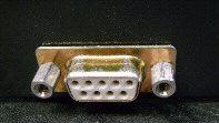
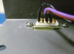
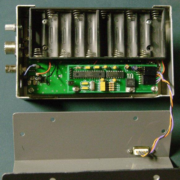
3 Mate the 8 pin connector to the 8 pin header on the DEC-001 board. Observe connector keying and note that there are two header connections, a 4 pin on top and an 8 pin next to the board. Locate the DB-9 connector wiring assembly supplied with the DEC-001. It will be necessary to mount the DB-9 connector in the side of the rear cover of the unit. Refer to Figure 10: DB-9 Installation. Cut out the template you want to use from the drawing and tape it to the right side of the cover. (Side opposite the battery holder.) Cut out goes near the bottom towards the back side. Refer to the DB-9 Hole Cutout drawing at the end of this document. Put masking tape on the opposite side of the cover to prevent scratches while working to make the DB- 9 cut out. Spot punch the hole locations. Then start with a small drill bit and work up to the final hole size. Final cut out is completed using a nibbling tool and or small file. De-burr all sharp edges. Take your time and make trial fits of the DB-9 connector periodically. Install the DB-9 connector wiring assembly in the cutout of the cover using the hardware supplied. Note that the DB-9 connector is mounted from the outside. Apply a small amount of locktite to the threads of the hex posts. Mate the 4 pin connector to the 4 pin header on the DEC-001 board. Observe connector keying. The 4 pin connector will now be lying on top of the 8 pin connector. You are now ready to re-connect the battery holder wires. If will be necessary to splice the red and black wires that were cut earlier. Use a short piece of shrink sleeving to insulate the splices. Apply power to the analyzer and check for normal operation. Correct installation will not affect the normal operation of the analyzer. If the software has not been installed, do so now. Launch the program. Connect a serial cable between the analyzer and the computer. A USB to serial adapter may be used if a serial port is not available. Select the Port and then click on the Power button. The analyzer information should appear on the computer screen. Click on the Antenna ICON to display the Control Panel. Click the Calibration button and follow the steps to calibrate the analyzer. Re-mount the battery holder using the screws and washers previously removed. Use caution not to pinch any wires where the battery holder contacts the hex stand offs. You analyzer should now look like Figure 11: Final Installation. Re-install the cover and secure with the 8 screws previously removed.


4 Installation Figures Figure 1: Battery Holder Removal Figure 2: Battery Holder Wires


5 Figure 3 MFJ-269 Test Point Locations Figure 4 MFJ-269C Test Point Locations


6 Figure 5 MFJ-259B Test Point Locations Figure 6 MFJ-259C Test Point Locations

7 Figure 7: Wiring Harness Installation


8 Figure 8: Hex Post Installation Fig ure 9: DEC-001 Board Installation

9 Figure 10: DB-9 Installation Figure 11: Final Installation
10 Troubleshooting Operation 1. Make sure your SWR Analyzer is operating correctly by its self. Correct wiring to the DEC-001 will have no effect on the normal operation of the SWR Analyzer. If the SWR Analyzer does not operate correctly and is not correctly calibrated, the DEC-001 will not provide reliable data to the remote computer. 2. Disconnect the MFJ Header connector. This will completely isolate the DEC-001 circuit board from the SWR Analyzer. If the SWR Analyzer still does not operate correctly, look for solder shorts at the wire connections added to the main circuit board. Also check for the possibility of any pinched wires that may have occurred. 3. Connect a 50 ohm load to the SWR Analyzer Antenna connector and set the Frequency Switch to the 4-10 MHz range. The LCD should indicate: The correct frequency R should be approximately 50 X should be approximately 0 SWR should be approximately 1.0 DEC-001 Operation 3. With the MFJ Header connection restored and the 50 ohm load connected in step 3 above, check the DC voltages on the three terminal regulator, U3. Input voltage should be >10 VDC and output voltage should be 4.8 to 5.2 VDC. 4. Check that the Heart Beat LED is flashing. Flashing at approximately once per second indicates the program in U2 is running and that the crystal oscillator is operating. The actual rate of flashing is not critical and may vary slightly. 5. Measure the voltage on pin 5 of U2. It should be approximately 2.50 VDC. 6. Measure the voltage on pin 7 of U2. It should be approximately 0.00 VDC. 7. Measure the voltage on pin 3 of U2. It should be approximately 1.25 VDC. 8. Measure the voltage on pin 2 of U2. It should be approximately 1.25 VDC. 9. Measure the voltage on pin 2 of U1. It should be approximately +8.5 VDC. 10. Measure the voltage on pin 6 of U1. It should be approximately -8.5 VDC. RS-232 Operation 11. Disconnect the RS-232 cable to the remote computer from the DB-9 connector on the SWR Analyzer cover. Measure the voltage on pin 3 of the DB-9 connector on the SWR Analyzer cover. It should be approximately 0 VDC. (Same as pin 13 of U1).
11 12. Measure the voltage on pin 4 of the DB-9 connector on the SWR Analyzer cover. It should be approximately -8.5 VDC. (Same as pin 14 of U1). 13. Measure the resistance between pin 5 of the DB-9 connector on the SWR Analyzer cover and ground at the DEC-001 circuit board. It should be <3 ohms. 14. Be sure you have a straight through RS-232 cable to the remote computer. A null modem cable will reverse the RX and TX data lines. 15. Check your RS-232 cable for continuity. Only the following 3 connections are used. Pin 5 to pin 5 Pin 3 to pin 3 Pin 2 to pin 2 Faulty Bridge Diode 16. A very common failure mode for these instruments is the 4 diodes in the RF bridge circuit. These diodes are HSMS 2820 Schottky diodes and are available from various sources such as Digi-Key. They are surface mount parts and have a minimum breakdown voltage of only 15 volts. It does not take much more than this to damage one or more of them. To make matters worse, two of them are connected directly to the RF connector and the other two only have a 50 ohm resistor between them and the antenna connector. Connecting an antenna with a static charge to the instrument is likely to cause damage. You should always discharge anything before making a connection to your analyzer. Often the damage is not readily apparent. The instrument will still read SWR, R and X but the accuracy will be very poor and the instrument can not be calibrated without first being repaired. If after installing the DEC-001 you cannot get the calibration pots to adjust correctly, you most likely have a bad diode(s). The telltale sign is not being able to set the high values for VS, VZ and VR using the calibration pots on the main board of the analyzer. They will have lower than normal readings due to low output from a leaky diode(s). Microcontroller Software Version 17. The micro-controller software version can be read by sending a?. The DEC-001 will respond with Version X.X where the X.X is a number such 1.3.

12 RS-232 Serial Data Communication The DEC-001 will communicate with a RS-232 terminal program such as RealTerm or other equivalent programs. The terminal program should be configured for 57,600 Baud, No Parity, 8 Data Bits and One Stop Bit. Sending the r character (lower case r for Read) will get a response with 7 lines of data as shown below. The first line is the A to D count for VZ. The second line is the A to D count for VS. The third line is the A to D count for VR. The fourth line is the A to D count for VF. The fifth line is the Frequency High Byte. Multiply this number by 65,536 for the decimal value. The sixth line is the Frequency Middle Byte. Multiply this number by 256 for the decimal value. The seventh line is the Frequency Low Byte. Multiply this number by 1 for the decimal value. The sum of these three frequency bytes in decimal form represents the frequency counter reading from the micro-controller. This sum should be multiplied by 8 or 4 (there is a prescaler in the SWR Analyzer) to get the actual counter numbers.
13 The frequency in the example above is calculated as follows: 0 * = 0 35 * 256 = 8, * 1 = 16 The sum is 0 + 8, = 8,976 8,976 * 8 = 71,808 The time base used by the counter is 10 ms. Therefore, multiply the number by 100 to get the frequency in Hz. 71,808 * 100 = 7,180,800 Hz or MHz Note: The example above is with a SWR Analyzer prescaler operating as divide by 8. Some SWR Analyzers use a divide by 4 prescaler.
14
15
Ameritron ALS-600 Retrofit ALS-600-LPF Assembly Manual
 Ameritron ALS-600 Retrofit ALS-600-LPF Assembly Manual FEATURES Automatic band change based on TX frequency. PIN diode QSK RX/TX switch. Temperature controlled FAN for quiet operation. RS-232 serial port
ELECRAFT Application Note
 ELECRAFT Application Note Front Panel Microphone Circuit Modification Revision A, November 12, 2008 Copyright 2008, Elecraft, Inc., All Rights Reserved Background Some K3 owners have noted distorted transmit
KX2 Side KX installation
 KX2 Side KX installation NOTE: The installation of any Side KX parts does NOT require the unsoldering of any connection nor removal of ANY of the boards from within the radio! The user/installer assumes
Field Service Procedure Replacement Pol Motor Kit, Coastal
 1. Brief Summary: Troubleshooting document for diagnosing a fault with and replacing the pol motor on the Coastal series antennas. 2. Checklist: Verify Motor Drive Drive the Pol from Progterm Run the Built
QRPGuys SMT Digital Dial/Frequency Counter
 QRPGuys SMT Digital Dial/Frequency Counter First, familiarize yourself with the parts and check for all the components. If a part is missing, please contact us and we will send one. You must use qrpguys.parts@gmail.com
MA6004 MA6002 MARINE AUDIO POWER AMPLIFIER OWNER S MANUAL. The Official Brand of Live Music.
 MA6004 MA6002 MARINE AUDIO POWER AMPLIFIER OWNER S MANUAL The Official Brand of Live Music. INSTALLATION THANK YOU for purchasing a JBL marine amplifier. In order that we may better serve you should you
Converting the Motorola 42 to 50 MHz MT1000 or P200 to 50 to 54 MHz
 Converting the Motorola 42 to 50 MHz MT1000 or P200 to 50 to 54 MHz Hardware mods by WB8VLC. RSS mods by WA1MIK Transmitter and receiver mods to tune the entire band and direct RSS frequency entry. Revision
INSTALLATION AND OPERATION MANUAL. Multiple-Radio Interface Module 41021G P-26 (11-12) 2012 David Clark Company Incorporated
 2012 David Clark Company Incorporated") INSTALLATI AND OPERATI MANUAL Multiple-Radio Interface Module 41021G-01 19537P-26 (11-12) 2012 David Clark Company Incorporated Table of Contents Cautions and Warnings... 1 Parts/Tools List... 2 Supplied
INSTALLATI AND OPERATI MANUAL Multiple-Radio Interface Module 41021G-01 19537P-26 (11-12) 2012 David Clark Company Incorporated Table of Contents Cautions and Warnings... 1 Parts/Tools List... 2 Supplied
OpenROV. Guide 3 - Electronics. We will now move to the assembly of the electronics that will control the ROV. Written By: OpenROV
 OpenROV Guide 3 - Electronics We will now move to the assembly of the electronics that will control the ROV. Written By: OpenROV 2017 openrov.dozuki.com Page 1 of 33 INTRODUCTION We will introduce soldering
MFJ 259 Operation & Simplified Calibration
 MFJ 259 Operation & Simplified Calibration Bill Leonard N0CU NA0TC 2014 TechFest 1 What Will Be Covered Part 1: Operation What is an MFJ 259 What Does It Measure Impedance & Admittance How Does It Work
Ocean Controls KT-5198 Dual Bidirectional DC Motor Speed Controller
 Ocean Controls KT-5198 Dual Bidirectional DC Motor Speed Controller Microcontroller Based Controls 2 DC Motors 0-5V Analog, 1-2mS pulse or Serial Inputs for Motor Speed 10KHz, 1.25KHz or 156Hz selectable
Explorer Wiring Kit (assembled)
") Explorer Wiring Kit (assembled) For Vintage, Firestorm & Standard Series Please Read All Instructions Before Beginning. Tools you will need: Soldering Iron (35 watt preferably) Solder Wet Sponge Wire Clippers
Explorer Wiring Kit (assembled) For Vintage, Firestorm & Standard Series Please Read All Instructions Before Beginning. Tools you will need: Soldering Iron (35 watt preferably) Solder Wet Sponge Wire Clippers
Build Notes Si570 Controller II - by Pete Juliano N6QW,
 Build Notes Si570 Controller II - by Pete Juliano N6QW, radioguy90@hotmail.com (As of June 10, 2012) I bought just the board and programmed Micro Controller Unit from K5BCQ. Therefore I had to purchase
PI-150 Broadband Power Indicator
 PI-150 Broadband Power Indicator HIGH RF VOLTAGES MAY BE PRESENT AT THE PORTS OF THIS UNIT. All operating personnel should use extreme caution in handling these voltages and be thoroughly familiar with
Manual AMERITRON QSK-5PC T/R SWITCH PC BOARD INTRODUCTION
 Manual Instruction AMERITRON QSK-5PC T/R SWITCH PC BOARD INTRODUCTION The Ameritron QSK-5PC is a PIN diode QSK circuit board designed for use in Ameritron's AL-80A, AL-80B, AL-82, AL-1500 and AL- 1200
DIODE / TRANSISTOR TESTER KIT
 DIODE / TRANSISTOR TESTER KIT MODEL DT-100K Assembly and Instruction Manual Elenco Electronics, Inc. Copyright 1988 Elenco Electronics, Inc. Revised 2002 REV-K 753110 DT-100 PARTS LIST If you are a student,
PI-10 Broadband Power Indicator
 PI-10 Broadband Power Indicator HIGH RF VOLTAGES MAY BE PRESENT AT THE PORTS OF THIS UNIT. All operating personnel should use extreme caution in handling these voltages and be thoroughly familiar with
SoftRock v6.0 Builder s Notes. April 6, 2006
 SoftRock v6.0 Builder s Notes April 6, 006 Be sure to use a grounded tip soldering iron in building the v6.0 SoftRock circuit board. The soldering iron needs to have a small tip, (0.05-0. inch diameter),
DIODE / TRANSISTOR TESTER KIT
 DIODE / TRANSISTOR TESTER KIT MODEL DT-100K 99 Washington Street Melrose, MA 02176 Phone 781-665-1400 Toll Free 1-800-517-8431 Visit us at www.testequipmentdepot.com Assembly and Instruction Manual Elenco
Pacific Antenna Code Practice Oscillator Kit
 Pacific Antenna Code Practice Oscillator Kit This kit is offered to initiate the first time builder in the various techniques of mechanical and electronic kit construction. At the end of the approximately
Telecaster Wiring Kits Please Read All Instructions Before Beginning. Tools you will need: Soldering tips: Removing Current Wiring: Step 1. Step 2.
 Telecaster Wiring Kits Please Read All Instructions Before Beginning. Tools you will need: Soldering Iron (35 watt preferably) Solder Wet Sponge Wire Clippers Wire Strippers 3/8 Drill Bit 5/32 Drill Bit
SoftRock v6.0 Builder s Notes. May 22, 2006
 SoftRock v6.0 Builder s Notes May 22, 2006 Be sure to use a grounded tip soldering iron in building the v6.0 SoftRock circuit board. The soldering iron needs to have a small tip, (0.05-0.1 inch diameter),
ScaleRCHelis.com V Light Controller Kit
 Thank you for purchasing the ScaleRCHelis.com V1.1 450 Light Controller Kit. This is something you can build in under a hour with some simple soldering equipment. Your kit will include all the parts necessary
SoftRock v5.0 Builder s Notes. December 12, Building a QSD Kit
 SoftRock v5.0 Builder s Notes December 12, 2005 Building a QSD Kit Be sure to use a grounded tip soldering iron in building the QSD board. The soldering iron needs to have a small tip, (0.05-0.1 inch diameter),
CP485-4 User s Manual
 CP485x4 User s Manual Version 1.0 2005 ZYPEX, Inc. CP485-4 User s Manual Table of Contents Table of Contents Product Description 1 CP485x4 Configuration & Setup 2 Power 2 Baud Rate 2 Control Mode 2 Duplex
Assembly and Installation Instructions for White Oak Audio Design PL400 Series 1 LED board
 Thank you for purchasing White Oak Audio Design s Phase Linear PL400 Upgrade LED Light Board. White Oak Audio Design products are meticulously engineered and tested to ensure a direct drop in fit with
Ocean Controls KT-5221 Modbus IO Module
 Ocean Controls Modbus IO Module 8 Relay Outputs 4 Opto-Isolated Inputs 2 Analog Inputs (10 bit) 1 PWM Output (10 bit) 4 Input Counters Connections via Pluggable Screw Terminals 0-5V or 0-20mA Analog Inputs,
IR add-on module circuit board assembly - Jeffrey La Favre January 27, 2015
 IR add-on module circuit board assembly - Jeffrey La Favre January 27, 2015 1 2 For the main circuits of the line following robot you soldered electronic components on a printed circuit board (PCB). The
PA FAN PLATE ASSEMBLY 188D6127G1 SYMBOL PART NO. DESCRIPTION. 4 SBS /10 Spring nut. 5 19A702339P510 Screw, thread forming, flat head.
 MAINTENANCE MANUAL 851-870 MHz, 110 WATT POWER AMPLIFIER 19D902797G5 TABLE OF CONTENTS Page DESCRIPTION.............................................. Front Page SPECIFICATIONS.................................................
BAND DECODER and CONTROLLE R. Accessibility Upgrade and Operating Instructions
 ELE CRAFT KRC2 BAND DECODER and CONTROLLE R Accessibility Upgrade and Operating Instructions Revision A, March 4, 2004. Copyright 2004, Elecraft; All Rights Reserved Introduction The KRC2 Accessibility
Custom Integrated Circuit (MSM9520RS) Replacement Module
 Replacement Module") FT-101Z/ FT-107/ FT-707/ FT-901,902 (later version) DISPLAY COUNTER UNIT (PB-2086A) Custom Integrated Circuit (MSM9520RS) Replacement Module Assembly and Installation Manual (v1.3e) STEP-BY-STEP PROCEDURES
FT-101Z/ FT-107/ FT-707/ FT-901,902 (later version) DISPLAY COUNTER UNIT (PB-2086A) Custom Integrated Circuit (MSM9520RS) Replacement Module Assembly and Installation Manual (v1.3e) STEP-BY-STEP PROCEDURES
SB.5.1 MODEL STRAIN GAGE CONDITIONER INSTRUCTION MANUAL. Instrument Series
 SB51 MODEL 3170 STRAIN GAGE CONDITIONER INSTRUCTION MANUAL 3000 Instrument Series Copyright 1996, Daytronic Corporation All rights reserved No part of this document may be reprinted, reproduced, or used
BL-ER-P Ethernet Radio Unit for Pedestal Installation Guide
 Assemble the Antenna Riser 1. Remove the antenna riser assembly and the antenna from its packaging. 2. Remove the plastic cap, the nut, and the lock washer from the stem of the antenna. 3. Put the stem
Harmony Remote Repair
 Harmony Remote Repair harmonyremoterepair.com How to install your new Harmony One Front Cover/Touch Screen Important! Before you begin working on your Harmony One, you must discharge any static electricity
RMD2000 DPO2000 and MSO2000 Series Rackmount Kit Instructions
 xx ZZZ RMD2000 DPO2000 and MSO2000 Series Rackmount Kit Instructions Warning The servicing instructions are for use by qualified personnel only. To avoid personal injury, do not perform any servicing unless
Directive Systems & Engineering 2702 Rodgers Terrace Haymarket, VA
 Directive Systems & Engineering 2702 Rodgers Terrace Haymarket, VA 20169-1628 www.directivesystems.com 703-754-3876 25 Element 7.4 wl. K1FO Designed Yagi, Model DSEFO432-25 ELECTRICAL SPECIFICATIONS Frequency
VHF 100/200 Series Radio Installation Instructions
 These installation instructions are for the following VHF radios and handsets: North American Models VHF 100 VHF 200 GHS 10 International Models VHF 100i VHF 200i GHS 10i Compare the contents of this package
KN-8828B Upgrade Directions
 KN-8828B Upgrade Directions This document outlines the steps to take to update earlier Hottop Bean Roasters to the KN-8828B 2007 by Chang Yue and Hottop USA - All Rights Reserved No part of this document
MFJ-219/219N 440 MHz UHF SWR Analyzer TABLE OF CONTENTS
 MFJ-219/219N 440 MHz UHF SWR Analyzer TABLE OF CONTENTS Introduction...2 Powering The MFJ-219/219N...3 Battery Installation...3 Operation Of The MFJ-219/219N...4 SWR and the MFJ-219/219N...4 Measuring
RMD5000 Rackmount Kit Instructions
 xx ZZZ RMD5000 Rackmount Kit Instructions www.tektronix.com *P075102000* 075-1020-00 Copyright Tektronix. All rights reserved. Licensed software products are owned by Tektronix or its subsidiaries or suppliers,
Repairing your Porsche 928 Central Warning System (CWS) controller
 controller") Repairing your Porsche 928 Central Warning System (CWS) controller Disclaimer: This procedure is for a 1984 Porsche 928 S controller. Overview: Under the left foot pedal (dead pedal) of the Porsche 928
Repairing your Porsche 928 Central Warning System (CWS) controller Disclaimer: This procedure is for a 1984 Porsche 928 S controller. Overview: Under the left foot pedal (dead pedal) of the Porsche 928
CP6A. 6 Band Trap Vertical 75-6m
 CP6A 6 Band Trap Vertical 75-6m Instruction Sheet The CP6A is a multi-band trap-vertical antenna for HF bands, covering the 75*, 40, 20, 15, 10m & 6m amateur bands. Made from heavy duty aluminum, the CP6A
New Life for the AM6154 and AM6155 John, W1AN 29 July, 2014
 New Life for the AM6154 and AM6155 John, W1AN 29 July, 2014 There are numerous sources for conversion information and modifications that have been shared over the years for the FAA AM6154 and AM6155 amplifiers
Pacific Antenna Field Strength Indicator Kit
 Pacific Antenna Field Strength Indicator Kit Description The Field Strength Indicator kit from Pacific Antenna provides a visual way to monitor the presence and relative strength RF fields through the
7878 K940. Checkpoint Antenna. Kit Instructions. Issue B
 7878 K940 Checkpoint Antenna Kit Instructions Issue B Revision Record Issue Date Remarks A July 7, 2009 First issue B Nov2013 Revised the Checkpoint installation procedures for 7878 and 7874 scanners Added
Battle Crab. Build Instructions. ALPHA Version
 Battle Crab Build Instructions ALPHA Version Caveats: I built this robot as a learning project. It is not as polished as it could be. I accomplished my goal, to learn the basics, and kind of stopped. Improvement
MFJ-249B HF/VHF SWR ANALYZER
 TABLE OF CONTENTS MFJ-249B... 2 Introduction... 2 Powering The MFJ-249B... 3 Battery Installation... 3 Alkaline Batteries... 3 NiCd Batteries... 4 Power Saving Mode... 4 Operation Of The MFJ-249B...5 SWR
Ameritron RCS-10 INTRODUCTION
 Ameritron RCS-10 INTRODUCTION The RCS-10 is a versatile antenna switch designed for 50-ohm systems. It handles high power, and sealed relays offer excellent life and connection reliability. It requires
PS4. Ragnarok Flex Modchip Installation Instructions.
 PS4 Ragnarok Flex Modchip Installation Instructions Revised 11/25/2013 Tools needed PS4 Controller Viking PS4 Ragnarok Flex modchip DIY Kit (includes mod chip, LED board, and LED lense) Two diodes (included
THE TOOLS RECOMMENDED Phillips Screwdriver Stripper/Crimper Electrician Pliers ½ open end wrench or ratchet wrench with ½ deep socket Utility knife
 16 X 20 HEATER ELEMENT WIRE CONNECTION REPAIR DK20/A/S/SP The following instructions are on the repair of a potentially faulty wire connection in your 16 x 20 heat platen. It is recommended that only those
Maintenance Information
 47104302 Edition 1 November 2012 Cordless Drill/Driver QX Series Maintenance Information Save These Instructions Tool Diagnosis 1. Before servicing this unit, you will need a fully charged battery of known
INSTALLATION INSTRUCTIONS
 INSTALLATION INSTRUCTIONS Accessory Application Publications No. AII 33380 SIDE S 2007 S2000 Issue Date AUG 2006 PARTS LIST Left upper side strake 2 Grommets 2 Butyl O-rings 2 Washer-screws, 6 x 20 mm
installation guide 1 GUIDE#: PWB-wwpontoon-pol-004
 f250 pontoon WAKEBOARD tower installation guide INSTALLATION SUPPORT 1 important information This WakeWorks tower fits Pontoon boats with 96 to 102 inch wide beam widths. This measurement is taken from
Custom Front Panel Upgrade Instructions
 Custom Front Panel Upgrade Instructions Here are the directions for upgrading your SP-II to an SP-IIB, with a custom blackanodized front panel and engraved lettering. There are only forty SP-IIB s in existence
FMR622S DUAL NARROW BAND SLIDING DE-EMPHASIS DEMODULATOR INSTRUCTION BOOK IB
 FMR622S DUAL NARROW BAND SLIDING DE-EMPHASIS DEMODULATOR INSTRUCTION BOOK IB 1222-22 TABLE OF CONTENTS SECTION 1.0 INTRODUCTION 2.0 INSTALLATION & OPERATING INSTRUCTIONS 3.0 SPECIFICATIONS 4.0 FUNCTIONAL
RCU-06 USER MANUAL. Introduction
 RCU-06 USER MANUAL Introduction The following manual will show the features and how to use the new antenna electronic controller. As you will see, it is by far the most simple and intuitive controller
Mastr III P25 Base Station Transmitter Tune-up Procedure
 Mastr III P25 Base Station Transmitter Tune-up Procedure 1. Overview The Mastr III Base Station transmitter alignment is performed in several steps. First, the Transmit Synthesizer module is aligned to
Serial Control Hardware (RS-485)
") Serial Control Hardware (RS-485) The RS-485 port is available on either of the RJ45 connectors on the back panel of the unit. The 485 network operates at 19.2 kbaud, 8 bits, 1 stop bit/no parity/no hardware
Serial Control Hardware (RS-485) The RS-485 port is available on either of the RJ45 connectors on the back panel of the unit. The 485 network operates at 19.2 kbaud, 8 bits, 1 stop bit/no parity/no hardware
ivu Plus Quick Start Guide P/N rev. A -- 10/8/2010
 P/N 154721 rev. A -- 10/8/2010 Contents Contents 1 Introduction...3 2 ivu Plus Major Features...4 2.1 Demo Mode...4 2.2 Sensor Types...4 2.2.1 Selecting a Sensor Type...5 2.3 Multiple Inspections...6 2.3.1
LED Field Strength Indicator Kit
 LED Field Strength Indicator Kit Description The Field Strength Indicator kit from Qrpkits.com provides a visual way to monitor RF fields through the brightness of an LED. It will respond to RF fields
Foxhunt Offset Attenuator. Parts List:
 When your closing in on the fox you may find the signals to be so strong that you can no longer find a peak or null with your antenna. Sometimes the signal is so strong that the RF will leak straight into
BABY WOLF LOOM. Assembly Instructions for Knocked-Down Looms
 BABY WOLF LOOM Assembly Instructions for Knocked-Down Looms BEFORE YOU BEGIN Please read through the directions before beginning to assemble your loom. Unpack the loom parts carefully. Do not throw away
Harris IRT Enterprises Multi-Channel Digital Resistance Tester Model XR
 Harris IRT Enterprises Multi-Channel Digital Resistance Tester Model 6012-06XR Specifications & Dimensions 2 Theory of Operation 3 System Block Diagram 4 Operator Controls & Connectors 5 Test Connections
MFJ 259B Analyzer Calibration
 Page 1 of 24 MFJ Enterprises Hy-Gain Ameritron Vectronics Mirage Search: All Search MFJ 259B Analyzer Calibration This is an MFJ procedure that does not contain any information that would not be handed
 Page 1 of 6 Page 1 of 12 Yaesu FT-5100/FT-5200 MODS Rev B (14 Apr 1993) This is a collection of hardware and software mods for the Yaesu 5100/5200 pair. I have the 5100, so I can't verify these for the
RAZOR. Class D Full Range & Monoblock Amplifiers RZ4-1200D RZ4-2000D RZ1-1500D RZ1-2300D
 RAZOR Class D Full Range & Monoblock Amplifiers RZ4-1200D RZ4-2000D RZ1-1500D RZ1-2300D WWW.POWERACOUSTIK.COM 4 Channel RZ4-1200D & RZ4-2000D Full MOSFET PWM Power Supply SMD Technology on Double Sided
Cricket 80a Assembly Manual v Copyright David Cripe NM0S The 4 State QRP Group
 Cricket 80a Assembly Manual v. 1.0 Copyright 2017 David Cripe NM0S The 4 State QRP Group Introduction Thank you for purchasing a CRICKET 80a Transceiver. We hope you will enjoy building it and find it
TA5604 Owner s Manual
 TA5604 Owner s Manual Introduction Thank you for choosing MTX to help reach the ultimate goal with your vehicle. Adding MTX amplifiers and matching MTX speakers and subwoofers with StreetWires connections
LED S METER CONSTRUCTION MANUAL. LED S meter Construction Manual Issue 1.0 Page 1
 LED S METER CONSTRUCTION MANUAL LED S meter Construction Manual Issue 1.0 Page 1 Important Please read before starting assembly STATIC PRECAUTION The LED S Meter kit contains components which can be damaged
EVDP610 IXDP610 Digital PWM Controller IC Evaluation Board
 IXDP610 Digital PWM Controller IC Evaluation Board General Description The IXDP610 Digital Pulse Width Modulator (DPWM) is a programmable CMOS LSI device, which accepts digital pulse width data from a
 INSTALLATION INSTRUCTIONS Accessory MOTORCYCLE BED P/N 08L26-SJC-100A Application 2011 RIDGELINE Publications No. AII 43440 Issue Date JUNE 2010 PARTS LIST Left tube 6 Hex bolts Right tube (with label)
2100L Broadband Power Amplifier
 2100L Broadband Power Amplifier HIGH RF VOLTAGES MAY BE PRESENT AT THE OUTPUT OF THIS UNIT. All operating personnel should use extreme caution in handling these voltages and be thoroughly familiar with
DEFENDER USER MANUAL
 Where The Money Meets The Machine PO Box 5128, 400 Regency Drive, Glendale Heights, IL 60139-5128 VOICE: 630/924-7070 1-800-323-6498 FAX: 630/924-7088 DEFENDER USER MANUAL Interchangeable with existing
TracVision M7 Gyro Replacement Instructions
 TracVision M Gyro Replacement Instructions The following instructions explain how to replace the azimuth or elevation gyro in a. IMPORTANT! Be sure to avoid causing sharp bends in cables when securing
FUNCTION GENERATOR KIT
 FUNCTION GENERATOR KIT MODEL FG-500K Assembly and Instruction Manual Elenco Electronics, Inc. Copyright 2005 by Elenco Electronics, Inc. All rights reserved. Revised 2005 REV-B 753069 No part of this book
NEW DESIGN***DEM Part Number FRS***NEW DESIGN Low power 144 MHz Transverter for the Flex Radio System SDR-1000 Operating Specifications:
 NEW DESIGN***DEM Part Number 144-28FRS***NEW DESIGN Low power 144 MHz Transverter for the Flex Radio System SDR-1000 Operating Specifications: Operating Voltage: 12.0-15.5 VDC, 13.8 nominal Current Drain:
Calibration Procedure for the Heathkit Antenna Tuner SA-2060 and SA2060A
 Calibration Procedure for the Heathkit Antenna Tuner SA-2060 and SA2060A Prepared by: Derf Mockford G8ZGK 17 November 2007 Page 1 Manufacturer: Models: Heathkit SA-2060, SA-2060A SPECIFICATIONS: Frequency
The ability to make basic voltage and resistance measurements using a digital multimeter
 Congratulations on your purchase of a new OneShot chassis! The PC01 OneShot combines a rugged enclosure, power supply, and discrete instrument DI in a compact 1/4U package. A few minutes of assembly are
RM4000 Tektronix 4000 Series Rackmount Kit
 Instructions RM4000 Tektronix 4000 Series Rackmount Kit 071-2134-01 Warning The servicing instructions are for use by qualified personnel only. To avoid personal injury, do not perform any servicing unless
DIY KITS FRAME KIT. Thank you for purchasing a 3DR Y6 DIY Kit!
 DIY KITS Y6 FRAME KIT Thank you for purchasing a 3DR Y6 DIY Kit! These instructions will guide you through assembling and wiring your new autonomous multicopter. CONTENTS Your 3DR Y6 Kit contains: 35 mm
************* OWNER'S MANUAL STAX1250/2 STAX1800/2 STAX2200/2 STAX1200/4 STAX1600/4 STAX2300/4 STAX2000/1D STAX4000/1D STAX5500/1D
 ************* OWNER'S MANUAL STAX1250/2 STAX1800/2 STAX2200/2 STAX1200/4 STAX1600/4 STAX2300/4 STAX2000/1D STAX4000/1D STAX5500/1D INTRODUCTION Power Acoustik amplifiers provide high-performance sound
MFJ-208 VHF SWR Analyzer
 MFJ-208 VHF SWR Analyzer Thank you for purchasing the MFJ-208 VHF SWR Analyzer. The MFJ-208 gives you a direct readout of your antenna's SWR without the need for formulas or indirect readings. The MFJ-
Direct Digital Synthesis System
 03March2011 N4YG Direct Digital Synthesis System Drake TR-7/RV-7 Installation & Users Manual TR-7/RV-7 DDS Installation The following is a step-by-step process for installing the N4YG DDS system into the
Standard Kit #1 (3-way switch)
") Standard Kit #1 (3-way switch) Please Read All Instructions Before Beginning. Tools you will need: Soldering Iron (35 watt preferably) Solder Wet Sponge Wire Clippers 3/8 Drill Bit 1/4 Drill Bit Variable
Standard Kit #1 (3-way switch) Please Read All Instructions Before Beginning. Tools you will need: Soldering Iron (35 watt preferably) Solder Wet Sponge Wire Clippers 3/8 Drill Bit 1/4 Drill Bit Variable
A 500 Broadband Power Amplifier
 A 500 Broadband Power Amplifier HIGH RF VOLTAGES MAY BE PRESENT AT THE OUTPUT OF THIS UNIT. All operating personnel should use extreme caution in handling these voltages and be thoroughly familiar with
LCD MULTIMETER FOR YOUR SHACK. MEASUREMENT U, I, P, Ah FOR GREEN ENERGY - WIND TURBINE, SOLAR PANELS. MEASUREMENT U, I, P, Ah, kwh
 LCD MULTIMETER FOR YOUR SHACK MEASUREMENT U, I, P, Ah FOR GREEN ENERGY - WIND TURBINE, SOLAR PANELS MEASUREMENT U, I, P, Ah, kwh www.sp2dmb.cba.pl sp2dmb@gmail.com MULTIMETER - ATMEGA8 Piotr Bryl SP2DMB
PTM Jazz Bass Control Plate Installation Revised: March 2, 2011
 PTM Jazz Bass Control Plate Installation Revised: March 2, 2011 Before you start, read these instructions first to understand what you need to do to install this product. Assumptions This patented Pickup
Modifying The Heath HA-14 For 6 Meters Greg Chartrand - W7MY 4/22/07
 Introduction The Heathkit HA-14 was one of the few electron tube linear amplifiers intended for mobile use but few were purchased with the 12 volt mobile power supply. Most hams bought the HA-14 for base
Modification of USB Sound Card for Asterisk app_rpt Use
 Modification of USB Sound Card for Asterisk app_rpt Use First off a huge thank you to Steve for providing the original notes on how to modify a USB sound card. (http://images.qrvc.com/usbfob.pdf) These
Giraud Tool Company, Inc.
 Motor Upgrade for Gracey Trimmer This package is intended to allow the user to upgrade their Gracey trimmer with a higher rpm motor and convenience features not found in the production offering. This upgrade
RMD3000 DPO3000 Series Rackmount Kit
 Instructions RMD3000 DPO3000 Series Rackmount Kit 071-2424-00 Warning The servicing instructions are for use by qualified personnel only. To avoid personal injury, do not perform any servicing unless you
Copyright 2013 Hughes Network Systems, LLC
 Copyright 2013 Hughes Network Systems, LLC All rights reserved. This publication and its contents are proprietary to Hughes Network Systems, LLC. No part of this publication may be reproduced in any form
KASTLE v1.5 - Assembly Guide
 last update: 14. 12. 2017 KASTLE v1.5 - Assembly Guide bastl-instruments.com INTRODUCTION Welcome to the assembly guide for the Kastle kit - mini modular synthesizer. It is suitable for beginners. It is
Installation & Service Manual
 869-894 MHz Installation & Service Manual Model SCA 9321-30C Single-Channel Cellular Amplifier 044-xxxxx Rev.A February 2003 2003 Powerwave Technologies Incorporated. All rights reserved. Powerwave Technologies,
MM340 Installation Instructions IMPORTANT SAFETY INSTRUCTIONS - SAVE THESE INSTRUCTIONS
 MM30 Installation Instructions IMPORTANT SAFETY INSTRUCTIONS - SAVE THESE INSTRUCTIONS Please read this entire manual before you begin. Do not unpack any contents until you verify all requirements on PAGE.
INSTALLATION AND MAINTENANCE MANUAL FOR GROUND MONITOR GM-250 COPYRIGHT 1983 AMERICAN MINE RESEARCH, INC.
 INSTALLATION AND MAINTENANCE MANUAL FOR GROUND MONITOR GM-250 COPYRIGHT 1983 AMERICAN MINE RESEARCH, INC. MANUAL PART NUMBER 180-0036 ORIGINAL: 1-17-83 REVISION: B (8-26-86) NOT TO BE CHANGED WITHOUT MSHA
ABM International, Inc. Navigator Assembly Manual
 ABM International, Inc. 1 1.0: Parts List Tablet (Qty. 1) Tablet mount (Qty. 1) NOTE: Mount may appear and operate different then image below Control Box (Qty. 1) Motor Power Supply (Qty. 1) 2 X-axis motor
INSTALLATION INSTRUCTIONS HEAVY DUTY TILT WALL MOUNT Model: PPH-2000
 INSTALLATION INSTRUCTIONS HEAVY DUTY TILT WALL MOUNT Model: PPH-2000 Specifications: Accomodates Akira and Orion 84" displays without interface bracket; accomodates other large flat panel displays with
Band-Master ATS Nano Pneumatic Banding Tool Operating Instructions
 Band-Master ATS 601-118 Nano Pneumatic Banding Tool CONTENTS 601-118 Overview... 3 Safety.... 5 Initial Tool Set-up... 5 Regulator assembly mounting... 5 Attach tool head to regulator.... 6 Operating instructions...
LCM100 USER GUIDE. Line Carrier Modem INDUSTRIAL DATA COMMUNICATIONS
 USER GUIDE INDUSTRIAL DATA COMMUNICATIONS LCM100 Line Carrier Modem It is essential that all instructions contained in the User Guide are followed precisely to ensure proper operation of equipment. Product