Copyright 2013 Hughes Network Systems, LLC
|
|
|
- Noah Hawkins
- 6 years ago
- Views:
Transcription


1
2 Copyright 2013 Hughes Network Systems, LLC All rights reserved. This publication and its contents are proprietary to Hughes Network Systems, LLC. No part of this publication may be reproduced in any form or by any means without the written permission of Hughes Network Systems, LLC, Exploration Lane, Germantown, Maryland Hughes Network Systems, LLC has made every effort to ensure the correctness and completeness of the material in this document. Hughes Network Systems, LLC shall not be liable for errors contained herein. The information in this document is subject to change without notice. Hughes Network Systems, LLC makes no warranty of any kind with regard to this material, including, but not limited to, the implied warranties of merchantability and fitness for a particular purpose. Trademarks Hughes and Hughes Network Systems are trademarks of Hughes Network Systems, LLC. All other trademarks are the property of their respective owners.
3 Contents Understanding safety alert messages... vii Messages concerning personal injury...vii Safety symbols... vii Chapter 1 Introduction...9 Hughes mobile satellite terminals...9 Below Deck Unit (BDU)...10 Physical dimensions...10 Power port...11 Table 2. Power port pin out...11 Four RJ-45 Ethernet with Power over Ethernet (PoE) ports...11 WLAN port...12 Antenna port...12 SIM card...12 System power requirements...13 Table 4. System power requirements...13 Fuse...13 Chapter 2 Below Deck Unit (BDU) Install...15 Basic BDU installation procedure...15 Installation notes...15 BDU mounting information...16 Chapter 3 Above Deck Unit (ADU) Install...17 Physical dimensions...17 Antenna cable lengths and types...17 Antenna Installation...17 Antenna Mounting...19 Antenna Magnetic Mounting...20 Antenna Vibration...21 Contents iii
4
5 Figures Figure 1-1. BDU (left) and ADU (right) Land Mobile antenna... 9 Figure 1-2. Below Decks Unit (BDU) Figure 1-3. Fitting the SIM card Cover Figure 2-1. BDU - mounting dimensions in mm Figure 2-2 BDU Wiring Diagram Figure 3-1. ADU Land Mobile Antenna Tables Table 1. Land Mobile Kit Parts Table 2. Power port pin out Table 3. RJ-45 Ethernet port pinout Table 4. System power requirements Figures v
6
7 Understanding safety alert messages Safety alert messages call attention to potential safety hazards and tell you how to avoid them. These messages are identified by the signal words WARNING or CAUTION, as illustrated below. To avoid possible property damage, personal injury, or in some cases possible death, read and comply with all safety alert messages. Messages concerning personal injury The signal words WARNING and CAUTION indicate hazards that could result in personal injury or in some cases death, as explained below. Each of these signal words indicates the severity of the potential hazard. WARNING indicates a potentially hazardous situation, which if not avoided, could result in death or serious injury. CAUTION indicates a potentially hazardous situation, which if not avoided, could result in minor or moderate injury. Safety symbols The generic safety alert symbol calls attention to a potential personal injury hazard. It appears next to the WARNING and CAUTION signal words as part of the signal word label. Other symbols may appear next to WARNING or CAUTION to indicate a specific type of hazard (for example, fire or electric shock). Safety vii
8
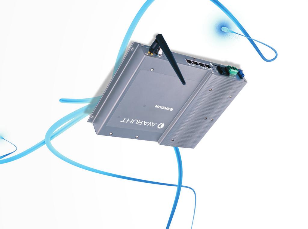
9 Chapter 1 Introduction The purpose of this guide is to provide assistance to personnel installing the Thuraya IP Voyager mobile satellite terminal into a vehicle. This terminal must be installed by Authorized Service Personnel. Note: Damages resulting in the failure to conform to the instructions found herein, as well as standard installation practices, will be the responsibility of the installer. Thuraya IP Voyager satellite terminals The Thuraya IP Voyager satellite terminal is composed of four core component parts: the transceiver or Below Deck Unit (BDU), the antenna or Above Deck Unit (ADU), the power connector/cable, and an RF cable. Figure 1-1. BDU (left) and ADU (right) Land Mobile antenna Package materials 9
 9506197-0001 WLAN antenna (2.")
10 The Thuraya Mobility (Land Mobile) kit is shipped with the following contents: Model Thuraya IP Voyager (9105) Land Mobile kit Hughes part Description number Radio, Thuraya IP Voyager (kit) WLAN antenna (2.4 GHz, 3 db) Power cable with 3-pin connector SIM cover plate Amp, fast blow, ATO blade fuse (2 pieces) PDF PDF Install Manual User Manual Land Mobile Antenna Type HN221 TNC-TNC/6m Table 1. RF coax cable TNC-TNC (6 meter) Land Mobile Kit Parts Below Deck Unit (BDU) The BDU provides all of the TE interfaces, plus the interface for the antenna (ADU) and manages the communications over the Thuraya network. Communication to the ADU is provided by a single RF cable from the BDU. Physical dimensions BDU: Size: 46mm x 281mm x 233mm Weight: 2.2kg Figure 1-2. Below Decks Unit (BDU) 10 The Below Deck Unit BDU
11 Power port The power port is the connection from the power supply (vehicle battery or some other 12 or 24Vdc power source) to the BDU. The power cable has a positive DC power line, a Remote Switch line and a negative DC power line. Line type Pin number V+ DC power line 1 Remote Switch 2 V- DC power line 3 Table 2. Power port pin out Four RJ-45 Ethernet with Power over Ethernet (PoE) ports There are four RJ-45 ports with Power over Ethernet (PoE) on the BDU. The ports supply standard PoE according to the IEEE 802.3af standard and 10/100BaseT Ethernet. The pinout of the ports supports a direct straight-through connection to a PC with a standard Ethernet cable. Table 3 shows the pinout of the Ethernet connector. Pin 1 RX+ 2 RX- 3 TX+ 4 NC 5 NC 6 TX- 7 NC 8 NC Table 3. RJ-45 Ethernet port pinout Note: The +48V and -48V are supplied over the TX, RX pairs. They are only active when an 802.3af compliant device is plugged in. The other pairs (4, 5, 7, and 8) are unused. The total power supplied by the PoE is limited to 30W maximum for 12V installations and 60W maximum for 24V installations. The BDU automatically detects the class of the device plugged in and will apply power so that the total cannot exceed these limits. If the user attempts to connect a combination of devices that require more than this, the BDU will not power any devices that would cause the limit to be exceeded. Note: Class 4 (802.3at) PD devices are not supported. Package materials 11

12 WLAN port The WLAN port on the BDU is a reverse polarity SMA jack. The supplied antenna is a 2.4 GHz 3dBi rubber duck antenna with RP-SMA plug connector supplied. To prevent blocking or attenuation of the WLAN signal, the BDU should be installed such that there is no metal blocking the radio path to the user s device. Antenna port The ADU (antenna) connects to the 50 Ohm female TNC connector antenna port on the BDU by an RF cable which carries L-band RF; signaling, & DC power (42Vdc) for the antenna. The antenna cable carries DC power; do not connect or disconnect the antenna cable while the unit is powered on. ONLY use the Thuraya Land Mobile Antenna Type HN221 with this BDU use of other antennas may damage the BDU and Antenna and shall void the warranty. SIM card SIM Card: The BDU requires a Thuraya SIM to be installed. Insert the SIM (supplied by your service provider) into the SIM card holder with the metal contacts facing down. A SIM card cover is supplied as an accessory with the BDU and may be utilized if desired. Use this to prevent accidental removal of the SIM card or if additional security is required. Note: the following tool (not supplied) is required to fit the SIM Card Cover: Screwdriver, Torx 8 (for a metric M2.5 screw). See Figure 1-3 for attaching the SIM card cover. 12 The Below Deck Unit BDU
13 Figure 1-3. Fitting the SIM card Cover System power requirements There is one power connection on the BDU. This must be connected to a 12 or 24Vdc supply. Power requirements and consumption are as follows: Voltage Input Minimum Voltage Input Maximum Total Current for ADU and BDU Required Fuse 10V 32V 12A 15A Table 4. System power requirements Fuse The fuse is a 15 Amp, fast blow, ATO blade fuse. The installed part is from Littelfuse, part number To replace the fuse, pull fuse out of fuse holder (pliers may be needed to grip fuse) and press new fuse into fuse holder. Spare fuses are provided with your Thuraya IP Voyager terminal. Power Cable The Power cable uses a Phoenix contact # PC5/3 STCL-7, 62 connector and the pinout is shown in the Table below. Color Function Red DC + White Ignition Sense + Black DC - The optional accessory car adapter power cable, Hughes part number , includes a car adapter plug with a 20 Amp, 250 V fuse, and the ignition sense wire is connected to the positive power wire in the plug. Package materials 13

14 Chapter 2 Standard Cable connections In addition to the DC power connection, an ignition sense connection must be made. This is done using the three-wire power cable. In the case of a vehicle installation, the power source is typically the vehicle battery. Cables should be routed appropriately, cable ties and clamps should be used as required to ensure that vibration and/or rubbing of the cables does not occur. Ignition sense (white wire) Route and connect the white wire (ignition sense) to a switched 12 or 24Vdc source, such as accessory line or fuse block. Extended use of ignition sense in the accessory position (ACC) by the end user may lead to a discharged car battery. Note: Ensure that the connection is a switched source: OFF when ignition is off or in start and ON only when ignition switch is in the ACCESSORIES or RUN position. Note: If using the optional car adapter plug, the ignition sense wire is already connected to the positive power wire in the plug. Chassis grounding The unit includes an isolating power supply. The BDU must be grounded by connecting a 8 AWG grounding wire from the chassis ground point to the vehicle chassis. See figure below. The ground wire should be clamped between the two nuts ensuring both are securely tightened. Chassis Ground Point 14 The Below Deck Unit BDU
15 Chapter 3 Below Deck Unit (BDU) Install The BDU is generally located in an area accessible by the operator and protected from water and heat. The ADU is generally located in a position to give clear line of sight to the satellite and to avoid exposure of microwave radiation to personnel. Basic BDU installation procedure The basic installation procedure is as follows: 1. Ensure that the BDU is located inside the vehicle in a position that is protected from water and heat and attached to something structurally solid. Locations that vibrate will degrade performance. Note: The BDU is not waterproof. 2. Determine the power cable routing from the BDU to the power source. 3. Determine an RF cable routing from the BDU to the ADU. The ADU will need to be mounted so that it has a 360 o clear view of the sky and is not within one meter of personnel in the vehicle (side and top surfaces). 4. Perform the installation of the BDU per the instructions below. Installation notes 1. Use the correct gauge of wire for both Positive and Negative wires to ensure a minimal voltage drop under load. Suggested wire size: 14 AWG: up to 8m (26ft), 12 AWG: up to 12m (40ft), 10 AWG: up to 20m (65ft). 2. The remote switch line may be used to power the system up and down remotely. It should be connected to a physical remote on/off switch or the vehicle s ignition line. When the engine is not running prolonged operation should be avoided to prevent draining the vehicle s battery. 3. The power must be connected to a fused 12 or 24Vdc power source. The unit is fused, but a 15A or greater fuse is required in the source to protect against shorts in the cabling. If connecting to a circuit in a DC panel that is already in use, ensure that the circuit can supply the unit with up to 15A for a 12V installation or 7.5A for a 24V installation. 4. Use cable ties every mm (12"-18"). 5. BDU - Ground the chassis ground bolt to a nearby vehicle ground point via an 8 AWG wire. 6. Whenever routing cable through holes drilled in metal or through bulkheads, use grommets and RTV sealant to weatherproof all holes drilled on the outside of the vehicle. 7. With the exception of the BDU-to-antenna RF cable, do not route the power cable outside the vehicle. Below Deck Unit (BDU) 15
.")
16 BDU mounting information 1. The BDU can be mounted in either the horizontal or vertical position. 2. Install the BDU in a protected but ventilated area. Allow at least a 1-inch space around top and sides to provide adequate cooling. 3. Mount the terminal onto a flat surface using at least four screws or bolts (not supplied). Use screws or bolts with a diameter between 3.5 to 4mm. Vibrationresistant screws or lock washers should be used. Dimension BETWEEN Mounting Holes: 271mm Dimen sion BETW EEN Mount ing Holes: mm Figure 2-1. BDU - mounting dimensions in mm. Figure 2-2 BDU Wiring Diagram 16 The Below Deck Unit BDU

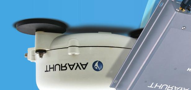
17 Chapter 4 Above Deck Unit (ADU) Install The antenna unit (ADU) is composed of the antenna element, high-power and lownoise amplifier systems, and a mechanical tracking system housed in the radome. The ADU is a SpaceCom HN221 2-axis antenna intended for vehicular use. Connection to the ADU is made by a TNC connector. The single coaxial cable carries L-band RX and TX, power, and control information. Physical dimensions ADU: Size: 252mm x 119mm Weight: 2kg Figure 3-1. ADU Land Mobile Antenna Antenna cable lengths and types The BDU has an automatic cable calibration feature that determines the loss of the cable. The RF cable that comes standard in the terminal kit is 6 meters long. If a different cable is required for the installation, the end-to-end RF loss needs to be 10dB +0dB/-8dB at 1.6GHz and the cable must be 50 Ohm impedance. Note: The installer is responsible for choosing the proper type of cable for the length required in order to meet the loss requirement. Antenna Installation When the Thuraya IP Voyager terminal is powered up - avoid exposure to microwave radiation. Keep a minimum safe distance of 1 meter (39 inches) to the side and above the antenna. The Antenna - Above Deck Unit (ADU) 17
18 The antenna cable carries DC power. Always power the BDU down prior to connecting or disconnecting the antenna cable from either the antenna or the BDU. Keep a clear line-of-sight to the satellite. Preferably, avoid all obstructions within three meters of the antenna. Obstructions less than 150 mm (six inches) in diameter can be ignored beyond this distance. Do not locate the antenna close to interfering signal sources or receivers. It is recommended that no other antennas be located within three meters of the Thuraya Mobility antenna. If there is other equipment installed near the Thuraya IP Voyager terminal, it is recommended to operate all equipment simultaneously and verify there is no co-interference. It is important for the operation and life of the Antenna and safety of personnel that the mounting / fitting instructions are followed improper installation will void any warranty. 18 The Above Deck Unit (ADU)
19 Antenna Mounting Always install the antenna so that it is in a horizontal position, even if the surface on which it is installed e.g. roof of a vehicle, is not horizontal. The antenna has three drainage holes at the bottom. Always install the antenna so that clearance between bottom of antenna with drainage holes and mounting surface is no less than 5 mm and preferably 10mm, refer to Fig.2. In order to fulfill these criteria a set of bolts and washers has to be defined for each individual installation, refer to Fig.1. The M5 stainless steel washers/rubber washers and spacers in the kit are always used and positioned as shown in Fig.1. The 3 spacers will have identical length if the antenna is installed on a non-tilting surface, but may require individual length adjustment if the surface is tilting. The M5 stainless steel bolts will have identical length if the three spacers are identical and may require individual length adjustment if spacer length are different. Note 1: Drainage of the antenna - a simple mechanism in the form of three holes in the dome (plastic enclosure) bottom is used. The holes are made so that water e.g. solid drops is not likely to enter the dome and simultaneously water that has entered the dome or moisture condensed in the dome is drained out simply by gravity. Correct function of the drainage system is ensured by following the correct installation requirements as shown in Figures 1 and 2. Note 2: Antenna Cable - it is important to protect against moisture using selfamalgamating tape (or similar) wrapped around the coaxial connector at the ADU. Also, secure the antenna cable at short intervals to prevent movement and stress. The Antenna - Above Deck Unit (ADU) 19
20 Antenna Magnetic Mounting Three magnetic mounts (part number ) are optional for the antenna installation. These mounts will withstand 100 mph wind force when properly installed on a flat metal surface such as a vehicle s roof. The magnet mount consists of three individual high-intensity magnets with rubber coating. Each magnet has a stainless steel center bolt. First attach the magnets to the antenna. There are three legs on the antenna where the magnets are placed. Note the position of the two rubber washers just below and above each antenna leg, the stainless steel washer above the upper rubber washer, and the protective nut on top. Now place the antenna with magnets on the roof of the car. When installing the antenna cable it is important to protect against moisture by using self-amalgamating tape, or similar, wrapped around the coaxial connector. Secure the RF cable at short intervals to prevent movement and stress. Note 1: Removing the Antenna - use your hand to pry underneath the antenna near one of the magnets and lift. 20 The Above Deck Unit (ADU)
21 Antenna Vibration The antenna is designed to meet the following operational vibration levels in any of three perpendicular directions measured at the mounting base of the radome Random Vibration: 1.05 grms with the following spectral density 5-20Hz.0.02g2/Hz Hz.-3dB/octave Single Frequency Vibration: 5-10Hz with amplitude 2.54 mm 10-15Hz with amplitude 0.76mm 15-25Hz with amplitude 0.40mm 25-33Hz with amplitude 0.23mm Note: Vibration levels in a typical installation are usually much less than the above mentioned values. It is however the responsibility of the installer to verify, that the cited levels are not exceeded in any mode of operation of the vehicle. In case of abnormal vibration, typically at a resonance frequency, measures must be taken in order to displace the resonance frequency or to dampen the vibration amplitude. The Antenna - Above Deck Unit (ADU) 21
22
23
24
Hughes 9450 Mobile Satellite Terminal. Installation Guide
 Hughes 9450 Mobile Satellite Terminal Installation Guide 3004129 Revision A September 15, 2010 Copyright 2010 Hughes Network Systems, LLC All rights reserved. This publication and its contents are proprietary
Thuraya Orion IP Satellite Terminal. Maritime Installation Guide
 Thuraya Orion IP Satellite Terminal Maritime Installation Guide 3500867-0001 Revision 2 November 27, 2013 Copyright 2013 Hughes Network Systems, LLC All rights reserved. This publication and its contents
Hughes 9450 Mobile Satellite Terminal
 Hughes 9450 Mobile Satellite Terminal Installation Guide 3004129-0001 Revision C Copyright 2011 Hughes Network Systems, LLC All rights reserved. This publication and its contents are proprietary to Hughes
Hughes 9450 Mobile Satellite Terminal Series. Installation Guide
 Hughes 9450 Mobile Satellite Terminal Series Installation Guide Document No. 3004129-0001 Revision E 17 November 2017 Copyright 2013, 2017 Hughes Network Systems, LLC All rights reserved. This publication
Hughes 9450 Mobile Satellite Terminal
 Hughes 9450 Mobile Satellite Terminal Installation Guide 3004129-0001 Revision C Copyright 2012 Hughes Network Systems, LLC All rights reserved. This publication and its contents are proprietary to Hughes
Hughes 9300 Series Mobile Satellite Terminal
 Hughes 9300 Series Mobile Satellite Terminal Installation Guide 1038494-0001 Revision E Copyright 2011 Hughes Network Systems, LLC All rights reserved. This publication and its contents are proprietary
MSAT-G2 Installation Guide
 Introduction... 1 Transceiver Unit (TU)... 3 Power Port... 4 Ethernet and Serial Ports... 4 RJ 45 Ethernet Port... 4 Serial Port... 5 Antenna Port... 5 Handset Port... 6 External Speaker... 6 System Power
Cisco Aironet 2.4-GHz/5-GHz 8-dBi Directional Antenna (AIR-ANT2588P3M-N)
") Cisco Aironet.4-GHz/5-GHz 8-dBi Directional Antenna (AIR-ANT588P3M-N) This document outlines the specifications for the Cisco Aironet AIR-ANT588P3M-N.4/5-GHz 8-dBi 3-Port Directional Antenna with N-connectors
Cisco Aironet.4-GHz/5-GHz 8-dBi Directional Antenna (AIR-ANT588P3M-N) This document outlines the specifications for the Cisco Aironet AIR-ANT588P3M-N.4/5-GHz 8-dBi 3-Port Directional Antenna with N-connectors
Cisco Aironet 13.5-dBi Yagi Mast Mount Antenna (AIR-ANT1949)
") Cisco Aironet 13.5-dBi Yagi Mast Mount Antenna (AIR-ANT1949) Overview This document describes the 13.5-dBi Yagi mast mount antenna and provides instructions for mounting it. The antenna operates in the
Cisco Aironet 13.5-dBi Yagi Mast Mount Antenna (AIR-ANT1949) Overview This document describes the 13.5-dBi Yagi mast mount antenna and provides instructions for mounting it. The antenna operates in the
Guide To Returning Your Satellite Modem and Radio Assembly Model: HN9000
 Guide To Returning Your Satellite Modem and Radio Assembly Model: HN9000 The HughesNet modem with power supply and radio must be returned to Hughes, in good condition, within 45 days of your service termination
VHF 100/200 Series Radio Installation Instructions
 These installation instructions are for the following VHF radios and handsets: North American Models VHF 100 VHF 200 GHS 10 International Models VHF 100i VHF 200i GHS 10i Compare the contents of this package
Cisco Aironet Omnidirectional Mast Mount Antenna (AIR-ANT2506)
") Cisco Aironet Omnidirectional Mast Mount Antenna (AIR-ANT2506) This document outlines the specifications, describes the omnidirectional mast mount antenna, and provides instructions for mounting it. Designed
Cisco Aironet Omnidirectional Mast Mount Antenna (AIR-ANT2506) This document outlines the specifications, describes the omnidirectional mast mount antenna, and provides instructions for mounting it. Designed
INSTALLATION MANUAL EXPLORER 325
 INSTALLATION MANUAL EXPLORER 325 EXPLORER 325 Document number: 98-131306-A Release date: June 17, 2010 Disclaimer Any responsibility or liability for loss or damage in connection with the use of this product
HP ProCurve 6.9/7.7dBi Dual Band Directional Antenna (J8999A) Guide
 Guide") HP ProCurve 6.9/7.7dBi Dual Band Directional Antenna (J8999A) Guide SAFETY The HP ProCurve J8999A and all associated equipment should be installed in accordance with applicable local and national electrical
HP ProCurve 6.9/7.7dBi Dual Band Directional Antenna (J8999A) Guide SAFETY The HP ProCurve J8999A and all associated equipment should be installed in accordance with applicable local and national electrical
Cisco Aironet Six-Element Dual-Band MIMO Patch Array Antenna (AIR-ANT25137NP-R)
") Cisco Aironet Six-Element Dual-Band MIMO Patch Array Antenna (AIR-ANT25137NP-R) August 2, 2013 This document describes the AIR-ANT25137NP-R antenna and provides instructions for mounting it. The antenna
Cisco Aironet Six-Element Dual-Band MIMO Patch Array Antenna (AIR-ANT25137NP-R) August 2, 2013 This document describes the AIR-ANT25137NP-R antenna and provides instructions for mounting it. The antenna
BRU-100 Physical Installation
 APPENDIX B BRU-100 In This Appendix: Warnings and Cautions, page 50, page 51 Check List, page 57 This appendix provides guidance for the physical installation of the BRU-100 Remote Unit at a subscriber
MA6004 MA6002 MARINE AUDIO POWER AMPLIFIER OWNER S MANUAL. The Official Brand of Live Music.
 MA6004 MA6002 MARINE AUDIO POWER AMPLIFIER OWNER S MANUAL The Official Brand of Live Music. INSTALLATION THANK YOU for purchasing a JBL marine amplifier. In order that we may better serve you should you
1369 & 1379 MOUNT KITS
 November 15, 2014 Lit. No. 64573, Rev. 01 1369 & 1379 MOUNT KITS 1369 Ford Bronco, F 150 4X4 1992-96 1379 Ford F 250/350 4X4 1992-97 Ford F 250 2WD (over 8,500 GVWR) 1992-97 Ford F 350 2WD (over 10,000
MPR kHz Reader
 MPR-5005 Page 1 Doc# 041326 MPR-5005 125kHz Reader Installation & Operation Manual - 041326 MPR-5005 Page 2 Doc# 041326 COPYRIGHT ACKNOWLEDGEMENTS The contents of this document are the property of Applied
BRIDGEABLE FOUR-CHANNEL POWER AMPLIFIER GM-A6604 GM-A4604. Owner s Manual
 BRIDGEABLE FOUR-CHANNEL POWER AMPLIFIER GM-A6604 GM-A4604 Owner s Manual Section 01 Before you start Thank you for purchasing this PIONEER product To ensure proper use, please read through this manual
FORD MOUNT INSTALLATION INSTRUCTIONS
 WESTERN PRODUCTS, P.O. BOX 245038, MILWAUKEE, WI 53224-9538 Lit. No. 67449 FORD MOUNT INSTALLATION INSTRUCTIONS Bronco, F-150/250/350 4X4 1992-1996 and Ford F-250 2WD (over 8,500 GVWR) Ford F-350 2WD (over
Instruction Manual for Universal Ku-band 8W BUC [NJT5218 series]
![Instruction Manual for Universal Ku-band 8W BUC [NJT5218 series]](/thumbs/96/127068123.jpg "Instruction Manual for Universal Ku-band 8W BUC [NJT5218 series]") Instruction Manual for Universal Ku-band 8W BUC [NJT5218 series] Document Part Number: IM-T5218 Revision: 00 Issue Date: June 15, 2012 Copyright 2012, New Japan Radio Co., Ltd. All rights reserved. This
Instruction Manual for Universal Ku-band 8W BUC [NJT5218 series] Document Part Number: IM-T5218 Revision: 00 Issue Date: June 15, 2012 Copyright 2012, New Japan Radio Co., Ltd. All rights reserved. This
INSTRUCTION MANUAL HF AUTOMATIC TUNING ANTENNA AH-740. * The stand in the photo is not supplied with the tuning antenna.
 INSTRUCTION MANUAL HF AUTOMATIC TUNING ANTENNA AH-740 * The stand in the photo is not supplied with the tuning antenna. FOREWORD Thank you for purchasing the AH-740 hf au to m at i c tuning antenna. The
EXPLORER 325. Installation manual
 EXPLORER 325 Installation manual EXPLORER 325 Document number: 98-131306-B Release date: January 28, 2015 Disclaimer Any responsibility or liability for loss or damage in connection with the use of this
MIRAGE BD-35 DUAL BAND POWER AMPLIFIER
 MIRAGE BD-35 DUAL BAND POWER AMPLIFIER INTRODUCTION: The Mirage BD-35 is a 45/35 watt dual band power amplifier for use with today's dual band handie talkies operating in the 144/440MHz bands. We have
CLASS D MONO AMPLIFIER GM-D8601 GM-D9601. Owner s Manual
 CLASS D MONO AMPLIFIER GM-D8601 GM-D9601 Owner s Manual Before you start BE SURE TO OBSERVE THE FOLLOWING GUIDELINES:! Do not turn up the volume so high that you can t hear what s around you.! Use caution
On-Line Cardio Theater Wireless Digital Transmitter Installation and Instruction Manual
 On-Line Cardio Theater Wireless Digital Transmitter Installation and Instruction Manual Full installation instructions accompany your Cardio Theater equipment order. This On-Line version of our Installation/Instruction
Cisco Aironet 12 dbi High Gain Omnidirectional Antenna (AIR-ANT24120)
") Cisco Aironet 12 dbi High Gain Omnidirectional Antenna (AIR-ANT24120) Overview This document outlines the specifications and description of the 12-dBi high gain omnidirectional antenna. This antenna operates
Cisco Aironet 12 dbi High Gain Omnidirectional Antenna (AIR-ANT24120) Overview This document outlines the specifications and description of the 12-dBi high gain omnidirectional antenna. This antenna operates
ALTAI A8N SERIES SUPER WIFI BASE STATION INSTALLATION GUIDE. Version 1.0 Date: September, Altai Technologies Ltd. All rights reserved
 ALTAI A8N SERIES SUPER WIFI BASE STATION INSTALLATION GUIDE Version 1.0 Date: September, 2013 Copyright 2007 Altai Technologies Limited ALL RIGHTS RESERVED. Altai Technologies Limited Unit 209, 2/F, East
WEL-200 O P E R A T I N G I N S T R U C T I O N S W I R E L E S S E D G E L I N K
 O P E R A T I N G I N S T R U C T I O N S WEL-200 TM W I R E L E S S E D G E L I N K 4564 Johnston Parkway, Cleveland, Ohio 44128 P. 800 426 9912 F. 216 518 9884 Sales Inquiries: salessupport@emxinc.com
KOP4800 Installation Guide
 KOP4800 Installation Guide This guide contains installation and safety information for your KING One Pro. Please read thru this guide before using or installing your KING One Pro. QUESTIONS? (952) 345-8147
SDI SPECTRADYNAMICS, INC. LOW NOISE FREQUENCY REFERENCE OPERATING MANUAL
 SPECTRADYNAMICS, INC. LOW NOISE FREQUENCY REFERENCE LNFR-100E OPERATING MANUAL SPECTRADYNAMICS, INC 1849 Cherry St. Unit 2. Louisville, CO 80027 Phone: (303) 665-1852 Fax: (303) 604-6088 www.spectradynamics.com
Western Products, PO Box , Milwaukee, WI MOUNT KIT. Model No Ford F-150 4X
 Western Products, PO Box 245038, Milwaukee, WI 53224-9538 www.westernplows.com November 1, 2009 Lit. No. 64461, Rev. 05 64500 MOUNT KIT Model No. 3239 Ford F-150 4X4 2004-08 Installation Instructions Read
MIRAGE BD-38-G DUAL BAND POWER AMPLIFIER
 MIRAGE BD-38-G DUAL BAND POWER AMPLIFIER MIRAGE BD-38-G Dual Band Amplifier INTRODUCTION: The Mirage BD-38-G is a 80/60 watt dual band power amplifier for use with today's dual band handie talkies operating
Guide. Installation. Wilson Electronics, Inc. Direct Connection High Power iden Amplifi er 800 MHz Band. Contents:
 Amplifier Installation Guide Direct Connection High Power iden Amplifi er 800 MHz Band Contents: Guarantee and Warranty 1 Before Getting Started / How it Works 3 Installing a Wilson Outside Antenna - In-Vehicle
Cisco Aironet Dual-Band MIMO Wall-Mounted Omnidirectional Antenna (AIR-ANT2544V4M-R)
") Cisco Aironet Dual-Band MIMO Wall-Mounted Omnidirectional Antenna (AIR-ANT2544V4M-R) This document outlines the specifications for the Cisco Aironet 2.4-GHz/5-GHz Dual-Band MIMO Wall-Mounted Omnidirectional
Cisco Aironet Dual-Band MIMO Wall-Mounted Omnidirectional Antenna (AIR-ANT2544V4M-R) This document outlines the specifications for the Cisco Aironet 2.4-GHz/5-GHz Dual-Band MIMO Wall-Mounted Omnidirectional
VHF 100/200 Series Radio Installation Instructions
 VHF 100/200 Series Radio Installation Instructions These installation instructions are for the following VHF radios and handsets: North American Models VHF 100 VHF 200 GHS 10 International Models VHF 100i
Yagi and Omni Antennas Installation Manual
 Yagi and Omni Antennas Installation Manual 25500445 Rev. A0 0218 Printed in U.S.A. Copyright 2018 Federal Signal Corporation Limited Warranty This product is subject to and covered by a limited warranty,
100W Wide Band Power Amplifier 6GHz~18GHz. Parameter Min. Typ. Max. Min. Typ. Max. Units. Frequency Range GHz Gain db
 100W Wide Band Power Amplifier 6GHz~18GHz Features Wideband Solid State Power Amplifier Psat: +50dBm Gain: 75 db Typical Supply Voltage: +48V On board microprocessor driven bias controller. Electrical
HT1100 Satellite Modem User Guide
 HT1100 Satellite Modem User Guide 1039650-0001 Revision C October 11, 2013 11717 Exploration Lane, Germantown, MD 20876 Phone (301) 428-5500 Fax (301) 428-1868/2830 Copyright 2013 Hughes Network Systems,
Commercial Vehicle Productivity and Security. Antenna Configuration. External Antenna Installation (model 6650H only) Contigo 6650H/6651H Beacon
 Contigo 6650H/6651H Beacon") Commercial Vehicle Productivity and Security The 6650H/6651H is a versatile and economical GPS tracking beacon designed for fleet management needs in all commercial vehicles. The H designation in the model
Commercial Vehicle Productivity and Security The 6650H/6651H is a versatile and economical GPS tracking beacon designed for fleet management needs in all commercial vehicles. The H designation in the model
MOUNT KIT. Ford F-150 4X Installation Instructions CAUTION. Read this document before installing the snowplow. CAUTION
 December 1, 2014 Lit. No. 64461, Rev. 06 64500 MOUNT KIT Ford F-150 4X4 2004-08 Installation Instructions Read this document before installing the snowplow. See your sales outlet/web site for specific
2015 RIGOL TECHNOLOGIES, INC.
 Service Guide DG000 Series Dual-channel Function/Arbitrary Waveform Generator Oct. 205 TECHNOLOGIES, INC. Guaranty and Declaration Copyright 203 TECHNOLOGIES, INC. All Rights Reserved. Trademark Information
RoamAbout Outdoor Antenna Site Preparation Guide
 9033153 RoamAbout 802.11 Outdoor Antenna Site Preparation Guide Notice Notice Cabletron Systems reserves the right to make changes in specifications and other information contained in this document without
Thuraya ATLAS IP+ Installation Manual
 Thuraya ATLAS IP+ Installation Manual Installation Manual Revision 1.0 LIST OF CONTENT: REGULATORY INFORMATION 3 SAFETY INSTRUCTIONS 4 IMPORTANT INFORMATION TO INSTALLERS AND USERS 7 ATLAS IP+ TERMINAL
Mobile Activation Case
 Mobile Activation Case Models MAC-01 and MAC-02 Description, Specifications, and Operations Manual 25500128 Rev. A1 0817 Printed in U.S.A. Copyright 2017 Federal Signal Corporation Limited Warranty This
Installation Job Aid (English) for Avaya WLAN 8100 series- WLAN AP 8120 with External Antenna
 for Avaya WLAN 8100 series- WLAN AP 8120 with External Antenna") Release 3.0 NN47251-311 Issue 02.01 June 2014 Installation Job Aid (English) for Avaya WLAN 8100 series- WLAN AP 8120 with External Antenna How to get help To access the complete range of services and
Release 3.0 NN47251-311 Issue 02.01 June 2014 Installation Job Aid (English) for Avaya WLAN 8100 series- WLAN AP 8120 with External Antenna How to get help To access the complete range of services and
Installation & Operating Manual. iwap202
 Installation & Operating Manual iwap202 This page is intentionally left blank. Document Number 409345 (based on 407655) (See Last Page for Revision Details) For warranty information, refer to Terms and
FORD MOUNT INSTALLATION INSTRUCTIONS
 WESTERN PRODUCTS, P.O. BOX 245038, MILWAUKEE, WI 53224-9538 Lit. No. 64289 June 1, 2003 FORD MOUNT INSTALLATION INSTRUCTIONS Bronco (4X4 only) F-150 (4X4 only), F-250/350 Super Duty 1980 1991 Model No.
CON NEX HP. OWNER'S MANUAL Full Channel AM/FM Amateur Mobile Transceiver TABLE OF CONTENTS TUNING THE ANTENNA FOR OPTIMUM S.W.R..
 TABLE OF CONTENTS PAGE SPECIFICATIONS... 2 INSTALLATION... 3 LOCATION... 3 CON NEX - 4300HP MOUNTING THE RADIO... 3 IGNITION NOISE INTERFERENCE... 4 ANTENNA... 4 TUNING THE ANTENNA FOR OPTIMUM S.W.R..
INSTALLATION INSTRUCTIONS ATV SNOW PLOW WARN KIT PN: KAWASAKI KIT PN: KAF Application: Kawasaki Prairie
 INSTALLATION INSTRUCTIONS ATV SNOW PLOW WARN KIT PN: 37838 KAWASAKI KIT PN: KAF90-220 Application: Kawasaki Prairie 1997-2002 Your safety, and the safety of others, is very important. To help you make
SAM. Model: STV-C65 LCD Mobile Visualized Stand Instruction Manual. Weight Capacity: 1251bs / 56.7kg Suits LCD Flat Panel Display: 42"-55" Page 20
 SAM Model: STV-C65 LCD Mobile Visualized Stand Instruction Manual Weight Capacity: 1251bs / 56.7kg Suits LCD Flat Panel Display: 42"-55" 20 Step 6 LCD Mobile Lift Stand Model: STV-C65 Cable management
Rain Gauge Smart Sensor (Part # S-RGA-M002, S-RGB-M002)
") (Part # S-RGA-M002, S-RGB-M002) The Rain Gauge smart sensor is designed to work with HOBO Station loggers. The smart sensor has a plug-in modular connector that allows it to be added easily to a HOBO Station.
(Part # S-RGA-M002, S-RGB-M002) The Rain Gauge smart sensor is designed to work with HOBO Station loggers. The smart sensor has a plug-in modular connector that allows it to be added easily to a HOBO Station.
INSTALLATION INSTRUCTIONS LARGE FLAT PANEL IN WALL ENCLOSURE Model: PAC-500
 INSTALLATION INSTRUCTIONS LARGE FLAT PANEL IN WALL ENCLOSURE Model: PAC-500 Specifications: Designed for in-wall installation spanning a minimum of 3 wood studs, 16" on center. Accomodates MWR, PWR and
PULSE DISTRIBUTION AMPLIFIER OPERATING MANUAL
 SPECTRADYNAMICS, INC PD5-RM-B PULSE DISTRIBUTION AMPLIFIER OPERATING MANUAL SPECTRADYNAMICS, INC 1849 Cherry St. Unit 2. Louisville, CO 80027 Phone: (303) 665-1852 Fax: (303) 604-6088 www.spectradynamics.com
5W Ultra Wide Band Power Amplifier 2-18GHz. Parameter Min. Typ. Max. Min. Typ. Max. Units
 7-3 RF-LAMBDA 5W Ultra Wide Band Power Amplifier 2-18GHz Features Wideband Solid State Power Amplifier Psat: + 37dBm Gain: 35 db Supply Voltage: +24V Electrical Specifications, T A = +25⁰C, Vcc = +24V
GPS Dome Installation Manual
 GPS Dome 1.01 Installation Manual Contents Introduction... 3 Overview... 3 Cautions... 4 Installation... 4 Installation Kit... 4 GPS Rece iver System with GPS Dome... 5 SMA Cables Connectors... 5 Installation
Installing the Hughes BGAN Remote Antenna
 Installing the Hughes BGAN Remote Antenna Product description BGAN Remote Antenna The Hughes BGAN Remote Antenna (HNS Part No. 9501286-0001) is designed to be permanently installed with the Basic Fixed
WINEGARD. Movin View
 WINEGARD TM Movin View Digital Satellite Mobile Antenna for Single Receiver Model MV-0055 Made in the U.S.A. U.S. Patent Nos. 6,023,247; 6,188,300 Winegard Company 3000 Kirkwood St. Burlington, IA 52601-2000
Advanced Test Equipment Rentals ATEC (2832)
") Established 1981 Advanced Test Equipment Rentals www.atecorp.com 800-404-ATEC (2832) 6500 Series Loop Antennas User Manual ETS-Lindgren Inc. reserves the right to make changes to any product described
Established 1981 Advanced Test Equipment Rentals www.atecorp.com 800-404-ATEC (2832) 6500 Series Loop Antennas User Manual ETS-Lindgren Inc. reserves the right to make changes to any product described
Cisco Outdoor Omnidirectional Antenna for 2G/3G/4G Cellular (ANT-4G-OMNI-OUT-N)
") CHAPTER 4 Cisco Outdoor Omnidirectional Antenna for 2G/3G/4G Cellular (ANT-4G-OMNI-OUT-N) The Cisco Outdoor Omnidirectional Antenna for 2G/3G/4G Cellular antenna is designed to cover domestic LTE700/Cellular/PCS/AWS/MDS,
CHAPTER 4 Cisco Outdoor Omnidirectional Antenna for 2G/3G/4G Cellular (ANT-4G-OMNI-OUT-N) The Cisco Outdoor Omnidirectional Antenna for 2G/3G/4G Cellular antenna is designed to cover domestic LTE700/Cellular/PCS/AWS/MDS,
8W Wide Band Power Amplifier 1GHz~22GHz
 8W Wide Band Power Amplifier 1GHz~22GHz Features Wideband Solid State Power Amplifier Gain: 50 db Typical Psat: +39 dbm Supply Voltage: +36V Electrical Specifications, T A = +25⁰C Typical Applications
ProCurve 7 dbi Dual Band Directional antenna
 GROUNDING System grounding and lightning protection are essential, especially for exterior-mounted antennas exposed to the elements. Never install an antenna where it may fall and contact electrical lines
GMR 420/620/1220 xhd2 Series Installation Instructions
 GMR 420/620/1220 xhd2 Series Installation Instructions To obtain the best performance and to avoid damage to your boat, install the device according to these instructions. Read all installation instructions
INSTALLATION AND OPERATION MANUAL. Multiple-Radio Interface Module 41021G P-26 (11-12) 2012 David Clark Company Incorporated
 2012 David Clark Company Incorporated") INSTALLATI AND OPERATI MANUAL Multiple-Radio Interface Module 41021G-01 19537P-26 (11-12) 2012 David Clark Company Incorporated Table of Contents Cautions and Warnings... 1 Parts/Tools List... 2 Supplied
INSTALLATI AND OPERATI MANUAL Multiple-Radio Interface Module 41021G-01 19537P-26 (11-12) 2012 David Clark Company Incorporated Table of Contents Cautions and Warnings... 1 Parts/Tools List... 2 Supplied
INSTALLATION INSTRUCTIONS HEAVY DUTY TILT WALL MOUNT Model: PPH-2000
 INSTALLATION INSTRUCTIONS HEAVY DUTY TILT WALL MOUNT Model: PPH-2000 Specifications: Accomodates Akira and Orion 84" displays without interface bracket; accomodates other large flat panel displays with
4-Port Antenna ircu / /65 16/18.5dBi 0 10 /0 10 T V01
 4-Port Antenna Frequency Range Dual Polarization Half-power Beam Width Integrated replaceable Remote Control Unit Adjustable Electrical Downtilt 0 10 0 10 4-Port Antenna 698 894/1710 2170 65 /65 16/18.5dBi
DD1-1300S. 500 Watts RMS Watts RMS Watts RMS- 1. Mono-Bloc Digital Power Amplifier
 DD1-1300S Mono-Bloc Digital Power Amplifier 500 Watts RMS- 4 900 Watts RMS- 2 Ultimate Sound, Inc. 1300 Watts RMS- 1 Ultimate Europe AB Ultimate Sound, Inc Ultimate Europe AB 163 University Parkway Flojelbergsgatan
30W Solid State High Power Amplifier 2-6 GHz. Parameter Min. Typ. Max. Min. Typ. Max. Units
 7-3 RF-LAMBDA 30W Solid State High Power Amplifier 2-6 GHz Features Wideband Solid State Power Amplifier Psat: +45dBm Gain: 50dB Supply Voltage: +36V Electrical Specifications, T A = +25⁰C, Vcc = +36V
GT-1050A 2 GHz to 50 GHz Microwave Power Amplifier
 Established 1981 Advanced Test Equipment Rentals www.atecorp.com 800-404-ATEC (2832) Giga-tronics GT-1050A Microwave Power Amplifier GT-1050A 2 GHz to 50 GHz Microwave Power Amplifier Operation Manual
Blizzard, PO Box , Milwaukee, WI UNDERCARRIAGE KIT. Dodge Ram 2500/3500. Installation Instructions CAUTION
 Blizzard, PO Box 245038, Milwaukee, WI 53224-9538 www.blizzardplows.com November 1, 2011 Lit. No. 41415, Rev. 01 33885 UNDERCARRIAGE KIT Dodge Ram 2500/3500 2010 - Installation Instructions Read this document
DC-20 GHz Distributed Driver Amplifier. Parameter Min Typ Max Min Typ Max Units
 7-3 RF-LAMBDA DC-20 GHz Distributed Driver Amplifier Electrical Specifications, T A =25 Features Ultra wideband performance Positive gain slope High output power Low noise figure Microwave radio and VSAT
HN System. Installation Manual for.74 m Ku-band Upgradeable Antenna Model AN6-074P
 HN System Installation Manual for.74 m Ku-band Upgradeable Antenna Model AN6-074P 1037087-0001 Revision B October 19, 2006 Copyright 2006 Hughes Network Systems, LLC All rights reserved. This publication
TZ-RD-1740 Rotary Dipole Instruction Manual
 TZ-RD-1740 17/40m Rotary Dipole Instruction Manual The TZ-RD-1740 is a loaded dipole antenna for the 40m band and a full size rotary dipole for the 17m band. The antenna uses an aluminium radiating section
INSTALLATION INSTRUCTIONS ATV WINCH MULTI-MOUNT Multi-Mount Mounting-Kit: PN Application: YAMAHA BIGBEAR 00+
 INSTALLATION INSTRUCTIONS ATV WINCH MULTI-MOUNT Multi-Mount Mounting-Kit: PN 61025 Application: YAMAHA BIGBEAR 00+ Your safety, and the safety of others, is very important. To help you make informed decisions
Optiva OTS-2 40 GHz Amplified Microwave Band Fiber Optic Links
 5 MHz to 4 GHz Amplified Microwave Transport System The Optiva OTS-2 4 GHz Microwave Band transmitter and receiver are ideal to construct transparent fiber optic links in the 5 MHz to 4 GHz frequency range
ABM International, Inc. Navigator Assembly Manual
 ABM International, Inc. 1 1.0: Parts List Tablet (Qty. 1) Tablet mount (Qty. 1) NOTE: Mount may appear and operate different then image below Control Box (Qty. 1) Motor Power Supply (Qty. 1) 2 X-axis motor
CP6A. 6 Band Trap Vertical 75-6m
 CP6A 6 Band Trap Vertical 75-6m Instruction Sheet The CP6A is a multi-band trap-vertical antenna for HF bands, covering the 75*, 40, 20, 15, 10m & 6m amateur bands. Made from heavy duty aluminum, the CP6A
Please read BOTH these Installation Instructions and the General Instructions before attempting to install or operate this equipment.
 Please read BOTH these and the General Instructions before attempting to install or operate this equipment. 1. Blue Ox towing products and accessories are intended to be installed by Blue Ox Dealers who
OB1U INSTALLATION INSTRUCTIONS. Interactive Flat Panel Over White Board Mount
 INSTALLATION INSTRUCTIONS Interactive Flat Panel Over White Board Mount Spanish Product Description German Product Description Portuguese Product Description Italian Product Description Dutch Product Description
Kit Kit. GeoSteer GS-900 Radio Kit. GS-900 Radio Kit Installation Instructions Rev A
 200-0652-01 Kit 200-0652-02 Kit GeoSteer GS-900 Radio Kit Item Component Part Number Qty Notes 1. Assembly, Radio GS-900 200-0642-01 (North America) 200-0642-02 (Australia) 1 Radio assembly in kit is region
INSTALLATION INSTRUCTIONS UTV LIGHT BAR KIT Part Number: and Application: All UTV s*
 INSTALLATION INSTRUCTIONS UTV LIGHT BAR KIT Part Number: 83970 and 84360 Application: All UTV s* * does not include Arctic Cat vehicles Your safety, and the safety of others, is very important. To help
RF-LAMBDA LEADER OF RF BROADBAND SOLUTIONS
 Electrical Specifications, T A =25 Ultra Wide Band Low Noise Amplifier AC 110V/220V 0.01-20GHz Parameters Min. Typ. Max. Min. Typ. Max. Units Frequency Range 0.01 10 10 20 GHz Gain 28 30 26 28 db Gain
Wall Mount Assembly and Mounting Guide (55 /84 )
") Microsoft Surface Hub Wall Mount Assembly and Mounting Guide (55 /84 ) For mounting on a wall with wood studs These instructions assume wood-stud wall construction with 2-by-4 studs spaced 16 inches apart,
Microsoft Surface Hub Wall Mount Assembly and Mounting Guide (55 /84 ) For mounting on a wall with wood studs These instructions assume wood-stud wall construction with 2-by-4 studs spaced 16 inches apart,
baseplate GMC Adadia & Buick Enclave
 , Rev 5 07/16 baseplate 9518214 GMC Adadia & Pin Height: 18 Centers: 24 5 8 10 6 11 7 2 4 9 3 1 ITEM PART # QTY DESCRIPTION 1 02990 2.3125NC X 1 HEX BOLT GR.5 2 00036 2.3125 LOCKWASHER 3 00007 2.3125NC
INSTALLATION INSTRUCTIONS WINCH MOUNTING PLATE Part Number: Application: 2007 JEEP JK WRANGLER
 INSTALLATION INSTRUCTIONS WINCH MOUNTING PLATE Part Number: 74247 Application: 2007 JEEP JK WRANGLER Your safety, and the safety of others, is very important. To help you make informed decisions about
VERTICAL PLATFORM LIFT
 VERTICAL PLATFORM LIFT HERCULES DC INSTALLATION GUIDE Please read this installation guide carefully to ensure correct installation of your HERCULES Vertical Platform Lift. HERCULES RESIDENTIAL & COMMERCIAL
WARNING. BX Ford Explorer With Adaptive Cruise Control & Eco Boost Installation Instructions
 Please read BOTH these and the General Instructions before attempting to install or operate this equipment. 1. Blue Ox towing products and accessories are intended to be installed by Blue Ox Dealers who
User Manual. ProRF Encoder Transmitter & Receiver
 User Manual ProRF Encoder Transmitter & Receiver WARRANTY Accurate Technology, Inc. warrants the ProScale Systems against defective parts and workmanship for 1 year commencing from the date of original
INSTALLATION INSTRUCTIONS Y-Connector Accessory (For Multi-Dual Arm Mounting Systems) Model: KSA-1011
 Model: KSA-1011") INSTALLATION INSTRUCTIONS Y-Connector Accessory (For Multi-Dual Arm Mounting Systems) Model: KSA-1011 Specifications: Installs to K-Series desk or wall mount. Accommodates K-Series mounting arms (fixed
INSTALLATION INSTRUCTIONS Y-Connector Accessory (For Multi-Dual Arm Mounting Systems) Model: KSA-1011 Specifications: Installs to K-Series desk or wall mount. Accommodates K-Series mounting arms (fixed
OMEGA. Communications Interface Cabinet. Antenna Installation Manual
 Ω OMEGA Communications Interface Cabinet Antenna Installation Manual 0049-0706-004 The products and programs described in this User s Guide are licensed products of Telenetics Corporation. This User s
SAILOR 150 FleetBroadband. Installation manual
 SAILOR 150 FleetBroadband Installation manual SAILOR 150 FleetBroadband Document number: 98-129218-B Release date: February 5, 2014 Disclaimer Any responsibility or liability for loss or damage in connection
MOUNT KIT. Dodge Ram 2500/3500 (All) Dodge Ram 2500/3500 (Gasoline only) Installation Instructions CAUTION
 Dodge Ram 2500/3500 (Gasoline only) Installation Instructions CAUTION") November 15, 2014 Lit. No. 41376, Rev. 05 33884 MOUNT KIT Dodge Ram 2500/3500 (All) 2010-12 Dodge Ram 2500/3500 (Gasoline only) 2013 - Installation Instructions Read this document before installing the
November 15, 2014 Lit. No. 41376, Rev. 05 33884 MOUNT KIT Dodge Ram 2500/3500 (All) 2010-12 Dodge Ram 2500/3500 (Gasoline only) 2013 - Installation Instructions Read this document before installing the
Specification. Spartan MA650.A.AB.002
 MA650.A.AB.002 on ground-plane Spartan MA650.A.AB.002 Specification Part No. Product Name Feature MA650.A.AB.002 Spartan 2in1 MA.650 with 10M cable length Low Profile Screw Mount (Permanent Mount) GPS/GLONASS
INSTALLATION AND MAINTENANCE MANUAL FOR GROUND MONITOR GM-250 COPYRIGHT 1983 AMERICAN MINE RESEARCH, INC.
 INSTALLATION AND MAINTENANCE MANUAL FOR GROUND MONITOR GM-250 COPYRIGHT 1983 AMERICAN MINE RESEARCH, INC. MANUAL PART NUMBER 180-0036 ORIGINAL: 1-17-83 REVISION: B (8-26-86) NOT TO BE CHANGED WITHOUT MSHA
Directive Systems & Engineering 2702 Rodgers Terrace Haymarket, VA
 Directive Systems & Engineering 2702 Rodgers Terrace Haymarket, VA 20169 1628 www.directivesystems.com 703 754 3876 K1JX DESIGNED 6 ELEMENT 50 MHZ YAGI, DSEJX6 50 INTRODUCTION The Directive Systems DSEJX6-50
MOUNT KIT. *equipped with Front Hitch/Winch Mount Installation Instructions CAUTION. Read this document before installing the snowplow.
 October 15, 2018 Lit. No. 74281, Rev. 01 MOUNT KIT Hustler MDV* 2017 - *equipped with Front Hitch/Winch Mount Installation Instructions Read this document before installing the snowplow. See your sales
TC ANT MOBILE... Mobile communication antennas and antenna cables. Data sheet _en_00. 1 Description
 Mobile communication antennas and antenna cables Data sheet 106760_en_00 PHOENIX CONTACT 2015-08-11 1 Description This data sheet describes the accessories for mobile communication products. All mobile
Model 7000 Low Noise Differential Preamplifier
 Model 7000 Low Noise Differential Preamplifier Operating Manual Service and Warranty Krohn-Hite Instruments are designed and manufactured in accordance with sound engineering practices and should give
Mirage B-34 FEATURES SPECIFICATIONS
 Mirage B-34 Mirage B-34 Instruction Manual The Mirage B-34 is a linear power amplifier designed for the 144-148 MHz band. It is the most useful and versatile amplifier available for handheld transceiver.