CP485-4 User s Manual
|
|
|
- Imogene Pierce
- 5 years ago
- Views:
Transcription


1 CP485x4 User s Manual Version ZYPEX, Inc. CP485-4 User s Manual Table of Contents
2 Table of Contents Product Description 1 CP485x4 Configuration & Setup 2 Power 2 Baud Rate 2 Control Mode 2 Duplex Mode 2 Termination 3 Key-Down Delay 3 Control Mode Description 4 RTS Mode 4 Data Mode 4 Duplex Mode Description 5 Full Duplex Mode 5 Half Duplex Mode 5 Termination Description 5 LEDs 5 DIP Switch Settings 6 Transient Protection and Grounding 7 Transient Protection 7 Shield Connection 7 Static Control 7 Connectors 9 Power 9 RS Power Consumption 9 Product Specifications 10 Contact Information 11 CP485-4 User s Manual Table of Contents
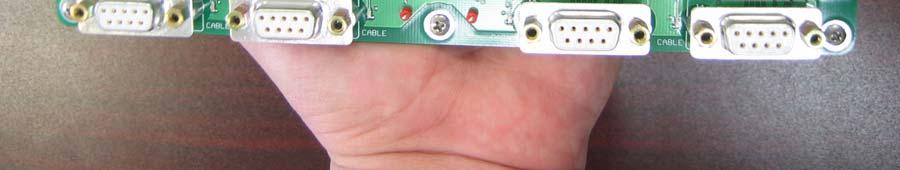
3 Product Description The CP485x4 line driver is a quad RS-232 to RS-485 interface converter. It allows an RS-232 device to reliably transmit data over long distances (up to 4000 feet). The CP485x4 has many features not normally found in typical line drivers, and is intended for operation in harsh industrial environments. The CP485x4 may be used in point-to-point applications as well as multi-drop applications using either 4-wire or 2-wire configurations. Up to 128 devices may be connected together on one communication line in half-duplex mode, or 64 devices in full-duplex mode. A variety of timing and control options are available on the CP485x4. Each channel is individually isolated, and may be operated in either RTS mode or Data mode. In RTS mode, the RS-232 RTS signal controls the RS-485 driver. In Data mode, the CP485 controls the RS-485 driver. When incoming data is detected on the RS-232 RX line, the CP485 enables the RS-485 driver, and starts buffering the incoming data. After a 2-character time delay (keyup delay), the data is transmitted on the RS-485 line. When all of the characters have been sent, the CP485 leaves the RS-485 driver enabled for a fixed time of either 50 or 500 microseconds (DIP Switch selectable) to allow the transmitted bytes to propagate out, and then disables the RS-485 driver (keydown delay). Electronic switches are used to control all configuration options. The user need only set the baud rate, duplex mode (full or half), control mode (RTS or Data) and whether the line is to be terminated. A unique capability of the CP485x4 is the ability to sense the presence of a received RS-485 carrier (remote RS-485 driver enabled). This is very useful for controlling devices that require a turn-on delay before data can be transmitted (e.g., devices such as radio modems). All timing functions are crystal controlled and provide very accurate and stable delays. Temperature and voltage fluctuations will not affect the CP485x4 s operation. The CP485x4 has 1500-volt optical isolation between the RS-232 side and the RS-485 side. The RS-485 lines are protected with 2 stages of surge protection. 1
4 CP485x4 Configuration and Setup Power Connect a DC power supply to J5 pins 1 & 2. Connect the positive side to J5 pin 1, and the common or return to J5 pin 2. Voltage can be 5 VDC to 30 VDC. CAUTION! The CP485 will be damaged if these connections are reversed! Connect J5 pin 3 to an earth ground. This connection enables the first stage of transient protection for each RS-485 channel, and keeps any static charge from building up on the RS-485 lines. The earth ground must be a short wire, directly to a suitable building ground, using 14-gauge wire (minimum size wire)!!! Baud Rate Set DIP Switches 1 3 to configure the channel for the desired baud rate (see DIP Switch Settings). The data format is automatically set to 8 data bits, no parity and 1 stop bit. Control Mode Set DIP Switch 4 to the desired Control Mode setting (RTS control or Data control). DATA mode is with DIP Switch 4 in the ON position. See the Control Mode Description in the next section for a full explanation of these two modes of operation. If you set DIP Switch 4 to ON, then you must set DIP Switch 7 to be either 8-bit mode or 9-bit mode (OFF or ON, respectively). Use 8-bit mode (in DATA mode only) if your data packets have either: 7 data bits, plus parity (odd or even) 8 data bits, no parity Use 9-bit mode (in DATA mode only) if your data packets are 8 data bits, with parity. Duplex Mode Set DIP Switch 5 to the desired Duplex Mode setting (full or half duplex). Full duplex is 4-wire mode, and half duplex is 2-wire mode. In half duplex mode, electronic switches connect the TX pair to the RX pair. The RS-485 lines may be connected to either the TX+ / TX- pair or the RX+ / RX- pair. 2
5 Termination Set DIP Switch 6 to enable or disable termination of the RS-485 trunk. The TERM LED will illuminate if termination is enabled. Key-Down Delay DIP Switch 8 is only used in DATA Mode, and allows you to set a very short or very long key-down delay. This is the amount of time that the RTS line is held ON, following the transmission of the last bit of the last byte of a data packet. The OFF position is a key-down time of 10 microseconds. The ON position of this switch makes the key-down time 50 microseconds. For short, hard copper lines, we recommend that this switch be in the OFF position. For slow devices like modems, we suggest that you position DIP Switch 8 in the ON position. Factory Test Options If any DIP Switch is moved (from OFF to ON, or ON to OFF) during the one- to two-seconds of power-up self-test (when the lights flash in the pretty power-up sequence, it is in self-test mode), then the CS485x4 enters a factory test mode. At this point, the various DIP Switches are used to enable various factory test options. The only way to get the CS485x4 out of this factory test mode is to unpower the device, wait a few seconds, then re-apply power. 3
6 Control Mode Description RTS Mode When RTS Mode is selected (DIP Switch 4 ON), the baud rate setting has no effect, and any type of data format may be used (7 data bits, even parity, 2 stop bits, or 8 data bits, odd parity, 1 stop bit, for example). The RS-232 RTS signal is used to control the RS-485 driver. Data Mode When Data Mode is selected (DIP Switch 4 OFF), DIP Switches 1 3 are used to set the baud rate. Data on the RX-232 RX line is used to control the RS-485 driver. The RS-232 RTS signal is not used. The data format handles both 1 and 2 stop bits. However, the CP485 does need to know how many TOTAL data bits (data plus parity) will be in each byte. The options are: 8-bit mode (7 data bits, plus a parity bit, or 8 data bits with no parity), or 9-bit mode (8 data bits, with a parity bit). DIP Switch 4 set to OFF selects 8-bit mode, while setting DIP Switch 4 to ON selects 9-bit mode. When incoming data is first detected on the RS-232 RX line, the RS-485 driver is enabled and the incoming data is stored in a buffer. After a 2-character time delay (for the selected baud rate), the buffered data is then transmitted out the RS-485 trunk. This allows the CP485 to provide a turn-on delay, which allows any transients on the RS-485 lines to settle before data is sent. After the transmission of the last character, the CP485 keeps the RS-485 driver enabled for some small time period (50 or 500 microseconds; DIP Switch selected) to allow the data to propagate down the RS-485 lines. This is called a key-down delay, and makes sure the data is completely received at the other end, before the RS-485 transmitted is disabled. This insures that the receiver on the end-devices does not have splatter or squelch noise at the end of the data packet, and yet is expected to be a short enough time period that no response from the other device is lost. This time is somewhat arbitrary, and you may have to try different settings of DIP Switch 8 to see what works best with your wiring and device configurations. Generally speaking, hard-copper lines don t require much key-down delay, and DIP Switch 8 should be OFF; whereas modems (especially RF modems) need much longer quiet times, and we suggest that these applications DIP Switch 8 should be ON. If you have problems with very slow (antique) devices, especially older, low-frequency RF modems, these timings can be changed at the factory Contact Zypex or Centaurus Prime if any longer time period is required for your particular application. 4
7 Duplex Mode Description Full Duplex Mode In Full Duplex Mode, data is transmitted on the TX+ / TX- pair, and data is received on the RX+ / RX- pair. The RX+ / RX- pair is always active. Half Duplex Mode In Half Duplex Mode, the TX+ / TX- pair is internally connected to the RX+ / RXpair. TX+ is connected to RX+, and TX- is connected to RX-. Either pair may be used (but not both). Termination Description If termination is enabled in full duplex mode, the TX+ / TX- pair is terminated and the RX+ / RX- pair if terminated. If termination is enabled in half duplex mode, the TX / RX combination is terminated. Termination consists of a 120-ohm resistor across the two RS-485 lines, plus a 1.2K pull-up resistor and a 1.2K pull-down resistor. LEDs RTS LED The RTS LED is illuminated when the RS-485 driver is enabled. TX LED The TX LED is illuminated when data is being transmitted on the RS-485 lines. RX LED The RX LED is illuminated when data is being received on the RS-485 lines. DCD LED The DCD LED is illuminated when the voltage on the RX+ / RX- pair is greater than 800mV. If the RX pair is terminated (either end), the DCD LED will illuminate when the remote RS-485 driver is enabled. If the RX pair is not terminated, the LED will be ON continuously. TERM LED The TERM LED is illuminated when the RS-485 channel is terminated. CABLE LED The CABLE LED is illuminated when an active RS-232 cable is plugged into the DB-9 connector. The LED will not illuminate if the RS-232 cable is crossed or improperly wired. 5
8 DIP Switch Settings Switch Description Switch 1 Switch 2 Switch 3 Baud Rate Select OFF OFF OFF 1200 Baud ON OFF OFF 2400 Baud OFF ON OFF 4800 Baud ON ON OFF 9600 Baud OFF OFF ON 19.2K Baud ON OFF ON 38.4K Baud OFF ON ON 57.6K Baud ON ON ON 115.2K Baud Switch 4 Switch 5 Switch 6 Switch 7 Switch 8 Data / RTS Mode OFF Data Mode ON RTS Mode Duplex Select OFF Half Duplex ON Full Duplex RS-485 Termination OFF No Termination ON Termination Enabled Data-Mode ONLY: total number of bits OFF 8-bit mode (e.g. 8-bit, no parity) ON 9-bit mode (e.g. 8-bit w/parity) Key-Down Delay OFF Normal (50 microseconds) ON Slow (500 microseconds) 6
9 Transient Protection and Grounding Transient Protection The CP485x4 has 2-stages of transient protection for each channel. The first stage connects each RS-485 data line to a SiDACtor. The common side of the SiDACtors are connected to the EARTH terminal of J5 (Figure 1). SiDACtor s provide ultra-fast transient response and provide a path to earth ground for highvoltage transients. The second stage of transient protection uses Transorbs that are connected to the isolated common of the RS-485 section. The Transorbs make sure all transient signals are clamped to within the normal operating voltage of the RS-485 electronics. Under certain conditions, some devices introduce a large ac or dc voltage on the RS-485 communication lines (referred to as common-mode voltage). This does not present a problem unless the common-mode voltage exceeds the SiDACtor s clamping voltage. If common-mode voltages in excess of 60V are expected, leave the connection from J5-3 (Earth) to ground open so that the SiDACtor s will not try to clamp the common-mode voltage to earth ground. The SiDACtor s and Transorbs will still provide transient protection, but not as effectively for very large transients (lightning for example). Leaving the Earth connection open allows the CP485x4 to operate reliably with common-mode voltages in excess of 100V. Shield Connection The isolated ground or common of the CP485x4 is connected to center pin of the RS-485 connector (SHLD). The connection is made through a 100-ohm resistor. The shield wires of the communication cables are normally connected to this point. Care must be taken to avoid ground loops. Only one end of the shield should be connected to earth ground. Under some conditions other devices may induce a large common-mode voltage on the shield wire. Under these circumstances, leave the CP485x4 s connection to earth ground (J5-3) open (see 485x4 Transient Protection and Grounding, and Figure 1). Static Control When pin J5-3 is connected to earth ground, the CP485x4 provides a bleed resistor which prevents static voltage buildup on the isolated section. The bleed resistor ensures that the isolated section is always at a safe voltage potential. The same connection provides a filter capacitor that deflects any high-frequency noise that may be induced on the RS-485 communication lines to earth ground. 7
10 8
11 Connectors Power (J5) Pin Description J Vdc to +30Vdc J5-2 Common for J5-1 J5-3 Earth Ground RS-485 (J7 J10) Pin Jx-1 Jx-2 Jx-3 Jx-4 Jx-5 Description TX+ TX- Isolated Common (Shield) RX+ RX- RS-232 (J1 J4) Pin Description Signal Jx-1 DCD Output Jx-2 RX Data Output Jx-3 TX Data Input Jx-5 Common Ground Jx-7 RTS Input Jx-8 CTS Output Power Consumption Voltage Current (Typical) 5 Vdc 1.0 Amp (inrush); 400 ma operational 12 Vdc 16 Vdc 24 Vdc 30 Vdc 9
12 CP485x4 Specifications RS-485 Channels Max Data Rate Line Loading Isolation Operation Data Format Input Voltage Transmit Control DCD Operation Status Indication 4 Individually Isolated RS-485 Channels 250kbps (RTS control) 1200 to 115.2K Baud (Data Mode) ¼ Load, 128 nodes / trunk 1500V RMS 2-wire Half-Duplex, 4-wire Full-Duplex 7 Data bits with parity, or 8 data bits (both with or without parity); 1 or 2 Stop Bits +5Vdc to +30Vdc Removable 3-pin connector RTS Control or DATA Control 2 character keyup delay (Data Mode ONLY) 50 or 500 microsecond key-down delay (Data Mode ONLY) True Carrier Detect or synthesized Data Detect LED Indicators for TX, RX, RTS, DCD Termination, RS232 Cable and Power Transient Protection Power Input RS-232 Port RS-485 Port Peak Pulse Power 600 watts (10/100us waveform) Peak Surge Current 100 amps (8.3ms single half sine-wave) ESD Protected ±15kV Human Body Model ±8kV Contact Discharge ±15kV Air-gap Discharge 2-Stage Surge Protection 1 st Stage: 150A Peak Pulse (2x10us waveform) 2 nd Stage: 600 watts (10x100us waveform) Operating Temperature Range 40 C to +85 C 10% to 90% RH (non-condensing) Size Mounting 4.0 in. 8.0 in. Standoffs with #4 machine screws 10
13 Contact Information ZYPEX, Inc E Bidwell Street # Folsom, CA (916) (916) fax info@zypex.com Contact Information Centaurus Prime 4425 Cass Street, Suites A-B San Diego, CA (858) (858) fax info@centaurusprime.com 11
ZCS485 User s Manual. Version ZYPEX, Inc.
 ZCS485 User s Manual Version 2.2 2004 ZYPEX, Inc. Table of Contents Product Description 1 ZCS485 Configuration & Setup 2 4-wire Operation 2 2-wire Operation 2 Dual Port Operation 2 Carrier Detect 2 Transmitter
CONV232/422 SERIAL DATA CONVERTER
 ACCES I/O PRODUCTS I. 06 Roselle St., San Diego CA 9-06 Tel (88)0-99 FAX (88)0-7 CONV/ SERIAL DATA CONVERTER DATA SHEET Model CONV/ is a bidirectional RS- to RS- converter. It converts full-duplex, single
Integrity Instruments
 Integrity Instruments XP-A/I User Manual Integrity Instruments P.O. Box Order Phone 00-0-00 Pine River Minnesota Fax Phone -- USA Tech Phone --0 http://www.integrityusa.com XP-A ISOLATED XP-I RS- to RS-
Universal Converter Covers All the Bases- RS-232 to 4-wire RS-422, 2-wire or 4-wire RS-485
 4WSD9R0712-1/4 Model 4WSD9R Universal Converter Covers All the Bases- RS-232 to 4-wire RS-422, 2-wire or 4-wire RS-485 The 4WSD9R Universal Converter is a port-powered or externally powered two-channel
Miniature Synchronous Multipoint Modems
 ME1735A-F JULY 2003 Miniature Synchronous Multipoint Modems CUSTOMER SUPPORT INFORMATION Order toll-free in the U.S.: Call 877-877-BBOX (outside U.S. call 724-746-5500) FREE technical support 24 hours
The I-2532 CAN to Fiber Converter
 The I-2532 CAN to Fiber Converter User s Manual Warranty All products manufactured by ICP DAS are under warranty regarding defective materials for a period of one year from the date of delivery to the
Applications. Operating Modes. Description. Part Number Description Package. Many to one. One to one Broadcast One to many
 RXQ2 - XXX GFSK MULTICHANNEL RADIO TRANSCEIVER Intelligent modem Transceiver Data Rates to 100 kbps Selectable Narrowband Channels Crystal controlled design Supply Voltage 3.3V Serial Data Interface with
Model FLSC-C3-XX. DC Powered Microprocessor Controlled Transmitter
 Model FLSC-C3-XX DC Powered Microprocessor Controlled Transmitter CONTENTS. Introduction----------------------------------------------------------------- 2 2. Specifications ---------------------------------------------------------------
Model 4xx. Plug-in Series Of FSK Modems USER GUIDE. (TI) 20 Jan 06 DWG: A GDI COMMUNICATIONS LLC PO Box I-80 Exit 1 Verdi, NV 89439
 20 Jan 06 DWG: A GDI COMMUNICATIONS LLC PO Box I-80 Exit 1 Verdi, NV 89439") Model 4xx Plug-in Series Of FSK s USER GUIDE (TI) 20 Jan 06 DWG: A01164 GDI COMMUNICATIONS LLC PO Box 1330 280 I-80 Exit 1 Verdi, NV 89439 Phone: (775) 345-8000 Fax: (775) 345-8010 Web: www.sgdi.com Email:
Model 4xx Plug-in Series Of FSK s USER GUIDE (TI) 20 Jan 06 DWG: A01164 GDI COMMUNICATIONS LLC PO Box 1330 280 I-80 Exit 1 Verdi, NV 89439 Phone: (775) 345-8000 Fax: (775) 345-8010 Web: www.sgdi.com Email:
Universal RS232/CMOS to RS422/RS485 Converter
 TOSHIBA INTERNATIONAL CORPORATION Universal RS232/CMOS to RS422/RS485 Converter Rev No.: 2 Page No.: 1 RS232/CMOS to RS422/RS485 Converter converts RS232/CMOS lines to balanced RS422 or RS485 signals.
ADA-1028L. User manual ADA-1028L. RS232 to Current Loop 2-wire CLO Converter. 1 io_ada-1028l_v.1.10_en. Copyright CEL-MAR sp.j.
 User manual ADA-1028L to Current Loop 2-wire Converter Copyright 2001-2017 CEL-MAR sp.j. 1 io_ada-1028l_v.1.10_en Contents 1. GENERAL INFORMATION... 3 1.1. WARRANTED INFORMATION... 3 1.2. GENERAL CONDITIONS
LCM100 USER GUIDE. Line Carrier Modem INDUSTRIAL DATA COMMUNICATIONS
 USER GUIDE INDUSTRIAL DATA COMMUNICATIONS LCM100 Line Carrier Modem It is essential that all instructions contained in the User Guide are followed precisely to ensure proper operation of equipment. Product
USB Port Medium Power Wireless Module SV653
 USB Port Medium Power Wireless Module SV653 Description SV653 is a high-power USB interface integrated wireless data transmission module, using high-performance Silicon Lab Si4432 RF chip. Low receiver
NetBiter I/O Extender 4RO 6RTD 8DIO - DAIO User Manual Revision 1.00
 NetBiter I/O Extender 4RO 6RTD 8DIO DAIO User Manual Revision 1.00 IntelliCom Innovation AB Linjegatan 3D SE302 50 Halmstad SWEDEN Phone +46 35 18 21 70 Fax +46 35 18 21 99 email info@intellicom.se www
PROMUX Distributed MODBUS I/O Modules Catalog and Design Guide
 PROMUX Distributed MODBUS I/O Modules Catalog and Design Guide 12/03/2012 V11.0 P.O.Box 164 Seven Hills 1730 NSW AUSTRALIA Tel: +61 2 96248376 Fax: +61 2 9620 8709 Email: proconel@proconel.com Web: www.proconel.com
PROMUX Distributed MODBUS I/O Modules Catalog and Design Guide
 PROMUX Distributed MODBUS I/O Modules Catalog and Design Guide 14/11/2006 V10 P.O.Box 24 Stanfield 3613 SOUTH AFRICA Tel: +27 (031) 7028033 Fax: +27 (031) 7028041 Email: proconel@proconel.com Web: www.proconel.com
SMARTALPHA RF TRANSCEIVER
 SMARTALPHA RF TRANSCEIVER Intelligent RF Modem Module RF Data Rates to 19200bps Up to 300 metres Range Programmable to 433, 868, or 915MHz Selectable Narrowband RF Channels Crystal Controlled RF Design
Serial Communications RS232, RS485, RS422
 Technical Brief AN236 Technical Brief AN236Rev A Serial Communications RS232, RS485, RS422 By John Sonnenberg S u m m a r y Electronic communications is all about interlinking circuits (processors or other
Data Acquisition Modules/ Distributed IO Modules
 User Manual Data Acquisition Modules/ Distributed IO Modules Future Design Controls, Inc. 7524 West 98 th Place / P.O. Box 1196 Bridgeview, IL 60455 888.751.5444 - Office: 888.307.8014 - Fax 866.342.5332
1 What s in the shipping package?
 SST 900B 900 MHz RS 232/RS 485 Wireless Modem Quick Start Guide 1 What s in the shipping package? SST-900B Wireless Modem CA-0910 Quick Start CD 3dBi 900M Hz Antenna Guide 2 External switch introduction
Interface: Serial EIA RS-232D/CCITT V.24, DCE; RTS/CTS delay 0,8 or 64 ms (user-selectable).
.") BLACK BOX PWR RTS TD-1 RD-1 TD-2 DCD RD-2 TEST DIG ANA REM LDM-MR 19.2 REM ANA DIG AGC 2/4 WIRE ABLE / ABLE SWITCHES 2 W 4 W 1 2 3 4 CARRIER LEVEL 0 dbm -3 dbm -6 dbm -9 dbm PIN 21 (RLB) RPF PIN 18 AN.
BLACK BOX PWR RTS TD-1 RD-1 TD-2 DCD RD-2 TEST DIG ANA REM LDM-MR 19.2 REM ANA DIG AGC 2/4 WIRE ABLE / ABLE SWITCHES 2 W 4 W 1 2 3 4 CARRIER LEVEL 0 dbm -3 dbm -6 dbm -9 dbm PIN 21 (RLB) RPF PIN 18 AN.
MULTI-DROPS DIGITAL MODEM FOR PRIVATE LINE
 Distribué par : Contact : hvssystem@hvssystem.com Tél : 0326824929 Fax : 0326851908 Siège social : 2 rue René Laennec 51500 Taissy France www.hvssystem.com MDM192 MULTI-DROPS DIGITAL MODEM FOR PRIVATE
USER'S MANUAL. Model : K
 USER'S MANUAL Model : 2000-64K TM GINA MODEL 2000-64K Overview GINA Model 2000-64K is a stand-alone, high frequency data transceiver using spread spectrum technology. GINA 2000-64K capabilities include
FOM-5A, 6A Asynchronous Fiber Optic Modems
 ORDERING FOM-5A/*/+ Asynchronous Sub-miniature Fiber Optic Modem FOM-6A/*/+/# Asynchronous Miniature Fiber Optic Modem * Specify: F for female 25-pin connector M for male 25-pin connector + Specify: ST
Moxa ICF-1280I Series Industrial PROFIBUS-to-Fiber Converter
 Moxa ICF-1280I Series Industrial PROFIBUS-to-Fiber Converter Hardware Installation Guide First Edition, August 2013 2013 Moxa Inc. All rights reserved. P/N: 1802012800011 Introduction The ICF-1280I series
USING RS-232 to RS-485 CONVERTERS (With RS-232, RS-422 and RS-485 devices)
") ICS DataCom Application Note USING RS- to RS- CONVERTERS (With RS-, RS- and RS- devices) INTRODUCTION Table RS-/RS- Logic Levels This application note provides information about using ICSDataCom's RS-
ICS DataCom Application Note USING RS- to RS- CONVERTERS (With RS-, RS- and RS- devices) INTRODUCTION Table RS-/RS- Logic Levels This application note provides information about using ICSDataCom's RS-
1.0 Introduction. Related Products and Documentation
 Quick Start t Guide ER450 Data Radio 1.0 Introduction Welcome to the Quick Start Guide for the ER450 Data Radio. This guide provides step-by-step instructions, with simple explanations to get you up-and-running.
PDL Base. Radio Modem User's Guide. Revision 0.2 (preliminary) May 1999 Copyright 1999 Pacific Crest Corporation Document M00522
 May 1999 Copyright 1999 Pacific Crest Corporation Document M00522") i PDL Base Radio Modem User's Guide Revision 0.2 (preliminary) May 1999 Copyright 1999 Pacific Crest Corporation Document M00522 Pacific Crest Corporation 990 Richard Avenue, Suite 110 Santa Clara, CA
i PDL Base Radio Modem User's Guide Revision 0.2 (preliminary) May 1999 Copyright 1999 Pacific Crest Corporation Document M00522 Pacific Crest Corporation 990 Richard Avenue, Suite 110 Santa Clara, CA
DEC-001 Installation Instructions
 DEC-001 Installation Instructions Skill Level: The installation of this assembly requires a medium level of expertise in working with modern electronic equipment. The use of appropriate tools, correct
A50/A51/A60. June 2008 (4th Edition) All Rights Reserved
 All Rights Reserved") A50/A51/A60 June 2008 (4th Edition) All Rights Reserved Part I - A50/A51 RS-232 to RS-422/RS-485 Converter A50/A51 RS-232 to RS-422/RS-485 Bidirectional Converter Part II - A60 RS-232 Surge Protection
A50/A51/A60 June 2008 (4th Edition) All Rights Reserved Part I - A50/A51 RS-232 to RS-422/RS-485 Converter A50/A51 RS-232 to RS-422/RS-485 Bidirectional Converter Part II - A60 RS-232 Surge Protection
Cross-Connect Interface
 Cross-Connect Interface User Manual Document #: 050-015-0036R01 November 2006 TASC Systems Inc. Langley, BC Canada Cross-Connect System User Manual Preface This document describes the installation, commissioning
SilverMax Datasheet. QuickSilver Controls, Inc. NEMA 23 Servomotors.
 SilverMax Datasheet NEMA 23 Servomotors QuickSilver Controls, Inc. www.quicksilvercontrols.com SilverMax Datasheet - NEMA 23 Servomotors 23 Frame Sizes: 23-3, 23-5, 23H-1, 23H-3, 23H-5 / Series: E, E3,
There are many important factors when trying to achieve good, reliable communications between 2 devices.
 APPLICATION NOTE THIS INFORMATION PROVIDED BY AUTOMATIONDIRECT.COM TECHNICAL SUPPORT These documents are provided by our technical support department to assist others. We do not guarantee that the data
PA FAN PLATE ASSEMBLY 188D6127G1 SYMBOL PART NO. DESCRIPTION. 4 SBS /10 Spring nut. 5 19A702339P510 Screw, thread forming, flat head.
 MAINTENANCE MANUAL 851-870 MHz, 110 WATT POWER AMPLIFIER 19D902797G5 TABLE OF CONTENTS Page DESCRIPTION.............................................. Front Page SPECIFICATIONS.................................................
Contents. Warranty and Disclaimer 2 Introduction 3
 Contents Warranty and Disclaimer 2 Introduction 3 Physical Dimensions Board Layout 4 Servo connections 5 Using the Serv8 Usage 6 Setting the start address 7 Setting the pulse width 8 Using the configuration
Lecture #3 RS232 & 485 protocols
 SPRING 2015 Integrated Technical Education Cluster At AlAmeeria E-626-A Data Communication and Industrial Networks (DC-IN) Lecture #3 RS232 & 485 protocols Instructor: Dr. Ahmad El-Banna 1 Agenda What
Concept of Serial Communication
 Concept of Serial Communication Agenda Serial v.s. Parallel Simplex, Half Duplex, Full Duplex Communication RS-485 Advantage over RS-232 Serial v.s. Parallel Application: How to Measure the temperature
M-Bus Master MultiPort 250L Installation and User Guide
 Installation and User Guide Kamstrup A/S Industrivej 28, Stilling DK-8660 Skanderborg T: +45 89 93 10 00 info@kamstrup.com kamstrup.com Contents 1 Introduction 3 1.1 Design 3 2 Functionality 4 2.1 Overview
FOSTCDR. Industrial Serial to Multimode Fiber Optic Converter PRODUCT INFORMATION B&B ELECTRONICS. Specifications Serial Technology
 FOSTCDR pn 8684R1 FOSTCDR-0812ds page 1/5 Industrial Serial to Multimode Fiber Optic Converter Data Rates up to 115.2 kbps 2.5 Mile (4 km) Range 10 to 30 VDC Input Voltage Wide Operating Temperature 2000V
Harris IRT Enterprises Multi-Channel Digital Resistance Tester Model XR
 Harris IRT Enterprises Multi-Channel Digital Resistance Tester Model 6012-06XR Specifications & Dimensions 2 Theory of Operation 3 System Block Diagram 4 Operator Controls & Connectors 5 Test Connections
APPLICATION BULLETIN. SERIAL BACKGROUNDER (Serial 101) AB23-1. ICS ICS ELECTRONICS division of Systems West Inc. INTRODUCTION CHAPTER 2 - DATA FORMAT
 AB23-1. ICS ICS ELECTRONICS division of Systems West Inc. INTRODUCTION CHAPTER 2 - DATA FORMAT") ICS ICS ELECTRONICS division of Systems West Inc. AB- APPLICATION BULLETIN SERIAL BACKGROUNDER (Serial 0) INTRODUCTION Serial data communication is the most common means of transmitting data from one point
ICS ICS ELECTRONICS division of Systems West Inc. AB- APPLICATION BULLETIN SERIAL BACKGROUNDER (Serial 0) INTRODUCTION Serial data communication is the most common means of transmitting data from one point
2070-6A Manual A Manual. Dual 1200 baud Modem For The 2070 Controller GDI A MANUAL
 2070-6A Manual 1 2070-6A Manual Dual 1200 baud Modem For The 2070 Controller GDI 2070-6A MANUAL This Manual covers Modems with the Serial numbers D700000 and up. 2070-6A Manual 2 GDI 2070-6A Manual This
SV613 USB Interface Wireless Module SV613
 USB Interface Wireless Module SV613 1. Description SV613 is highly-integrated RF module, which adopts high performance Si4432 from Silicon Labs. It comes with USB Interface. SV613 has high sensitivity
SPECIAL SPECIFICATION 6744 Spread Spectrum Radio
 2004 Specifications CSJ 0924-06-244 SPECIAL SPECIFICATION 6744 Spread Spectrum Radio 1. Description. Furnish and install spread spectrum radio system. 2. Materials. Supply complete manufacturer specifications
PRODUCT INFORMATION B&B ELECTRONICS. Port-Powered RS-232 Fiber Optic Modem with Handshake Support. Model 9PFLST. Description. RS-232 Connections
 -01-1/ 00 by B&B Electronics. All rights reserved. Model Port-Powered RS- Fiber Optic Modem with Handshake Support Description The allows any two pieces of RS- asynchronous serial equipment to communicate
2W UHF MHz Radio Transceiver
 2W UHF410-470 MHz Radio Transceiver Specification Copyright Javad Navigation Systems, Inc. February, 2006 All contents in this document are copyrighted by JNS. All rights reserved. The information contained
HURRICANE Radio Modem. FULL DUPLEX Radio MODEM
 FULL DUPLEX Radio MODEM Direct Cable Replacement Range 2KM RS232 / RS485 / USB Host Data Rates up to 38,400 Baud RF Data Rates to 115200Kbps Waterproof IP68 Enclosure 8 User Selectable Channels CE Compliant
SmartRadio Transmitter / Receiver
 Easy to use Radio Transmitter & Receivers AM Radio Hybrid Technology Supports Data or Telemetry communications Simple CMOS/TTL Data Interface Automatic data encryption / decryption Host Interface up to
TRXQ1 RXQ1 FM NARROW BAND TRANSCEIVERS. RXQ1 Version. Applications. TRXQ1 Version
 RF Transceiver or Intelligent Modem Versions Host Data Rate upto 19,200 Baud Data Rates to 20 K baud. 2 Selectable RF Channels Narrowband Crystal Controlled Optimal Range 200m Supply Voltage 3-5V Very
Maintenance Manual ERICSSONZ LBI-31552E
 E Maintenance Manual TONE REMOTE CONTROL BOARD 19A704686P4 (1-Frequency Transmit Receive with Channel Guard) 19A704686P6 (4-Frequency Transmit Receive with Channel Guard) ERICSSONZ Ericsson Inc. Private
MODEL: DLS. Telemetering System
 POW RUN SA SA RT RU MODEL: DLS Telemetering System TELEMETERING UNIT Functions & Features Interfacing remote I/O devices with a modem for a telemetering system Process I/O (.0) [] POWER INPUT AC Power
Contents. Warranty and Disclaimer 2
 Contents Warranty and Disclaimer 2 Physical Dimensions Board Layout 3 Usage Using the PWM board 4 Setting the start address 4 Dimming LED s 5,6 Typical hookup 7 Terminator 8 Troubleshooting Ground, termination,
Intermittent Vibration 0.075
 FEATURES DESCRIPTION PLC-COM-CM1 Series Multi Drop Configuration of up to 32 Units Baud Rates Range from 300 to 38,400 bps 1:1/1:N/N:M (RS-422) Communication is Supported Full-Duplex (RS-422) and Half-Duplex
WRM-10 TM TRANSFORMER WINDING RESISTANCE METER
 WRM-10 TM TRANSFORMER WINDING RESISTANCE METER USER S MANUAL Vanguard Instruments Company, Inc. 1520 S. Hellman Ave. Ontario, California 91761, USA TEL: (909) 923-9390 FAX: (909) 923-9391 June 2009 Revision
ST600 TRANSMITTER OPERATING INSTRUCTIONS
 ST600 TRANSMITTER OPERATING INSTRUCTIONS 1892 1273 These operating instructions are intended to provide the user with sufficient information to install and operate the unit correctly. The Wood and Douglas
Mastr III P25 Base Station Transmitter Tune-up Procedure
 Mastr III P25 Base Station Transmitter Tune-up Procedure 1. Overview The Mastr III Base Station transmitter alignment is performed in several steps. First, the Transmit Synthesizer module is aligned to
IMC-316P Hardware Manual for model IMC-316P-X-D
 IMC-316P Hardware Manual for model IMC-316P-X-D Pub 352r0 A publication of 1050 Highland Drive Ann Arbor, Michigan 48108 Phone: (734) 665-5473 Fax: (734) 665-6694 www.whedco.com 2000 Whedco Incorporated,
9600 bps, Dual Modem 170 Card Private Wire Only
 896 9600 bps, Dual Modem 170 Card Private Wire Only Users Guide 280 Interstate 80 West Exit 1 / PO Box 1330, Verdi, NV 89439 Phone: 775-345-8000 Fax: 775-345-8010 E-mail: traffic@sgdi.net TABLE OF CONTENTS
ADA User manual ADA RS-232 to RS-485 / RS-422 Converter
 User manual RS- to RS- / RS- Converter Copyright 001-01 CEL-MAR sp.j. 1 io_ada-100_v._en Contents 1. GENERAL INFORMATION... 1.1. WARRANTED INFORMATION... 1.. GENERAL CONDITIONS FOR SAFE USE... 1.. CE LABEL...
Modbus communication module for TCX2: AEX-MOD
 Modbus communication module for TCX2: Communication Specification TCX2 is factory installed in TCX2 series controllers with -MOD suffix, and is also available separately upon request for customer installation
Modem 1200 baud 500FSD10 EDS500 series - FSK modems
 Manual Modem 1200 baud 500FSD10 EDS500 series - FSK modems Application, characteristics and technical data have to be taken from the hardware data sheet: 500FSD10 Data sheet 1KGT150982 Operation The 500FSD10
Embedded Radio Data Transceiver SV611
 Embedded Radio Data Transceiver SV611 Description SV611 is highly integrated, multi-ports radio data transceiver module. It adopts high performance Silicon Lab Si4432 RF chip. Si4432 has low reception
The first RADIO Communication Module designed for the weighing industry
 The first RADIO Communication Module designed for the weighing industry SCALELINK - AURORA WIRELESS LINK Step 1: Get Connected A) Disconnect the indicator (or other device) from power. Connect the ScaleLink
LBI Installation & Operation
 Installation & Operation EDACS Power Monitor Unit ericssonz CONTENTS TABLE OF CONTENTS Page INTRODUCTION... 6 DESCRIPTION... 6 APPLICATION NOTES... 7 VAX SITE CONTROLLER COMPUTER... 7 APPLICATION SOFTWARE
Fanuc Serial (RS232) Communications Information
 Communications Information") Memex Automation Inc. 777 Walkers Line, Burlington, Ontario Canada L7N 2G1 Fanuc Serial (RS232) Communications Information Contents Signal Description Fanuc Serial Cable Information Timing Chart When The
Memex Automation Inc. 777 Walkers Line, Burlington, Ontario Canada L7N 2G1 Fanuc Serial (RS232) Communications Information Contents Signal Description Fanuc Serial Cable Information Timing Chart When The
96M0374. Instruction Manual. Analog Sensor Controller. RD Series
 Instruction Manual Analog Sensor Controller RD Series 96M0374 Safety precautions This manual describes how to install the RD Series as well as its operating procedures and precautions. Please read this
IB6 Series Solid-State Isolation Relay
 IB6 Series Solid-State Isolation Relay Installation & Operation Manual TRANSDATA, INC. 2560 TARPLEY ROAD CARROLLTON, TEXAS 75006 TEL (972) 418-7717 FAX (972) 418-7774 Website: www.transdatainc.com E-mail:
Guardian and DL3282 Modem Interface Technical Service Application Note
 Guardian and DL3282 Modem Interface Technical Service Application Note OVERVIEW The following document is designed to provide information for the implementation of the Guardian Wireless Modem/Analog Radio
SOLUTIONS FOR AN EVOLVING WORLD RFL Programmable FSK Powerline carrier system
 SOLUTIONS FOR AN EVOLVING WORLD RFL 9780 Programmable FSK Powerline carrier system Your world is changing and so are we. At RFL, we know your needs change much faster than your infrastructure. Our comprehensive
RM868500D. Introduction. Features. 868MHz 500mW RS232 / RS485 / RS422 Radio Modem. Operating Manual English 1.01
 RM868500D 868MHz 500mW RS232 / RS485 / RS422 Radio Modem Operating Manual English 1.01 Introduction The RM868500D radio modem acts as a wireless serial cable replacement and can wirelessly connect various
TD_485 Transceiver Modules Application Guide 2017
 TD_485 Transceiver Modules Application Guide 2017 1. RS485 basic knowledge... 2 1.1. RS485 BUS basic Characteristics... 2 1.2. RS485 Transmission Distance... 2 1.3. RS485 bus connection and termination
RS-232 Electrical Specifications and a Typical Connection
 Maxim > Design Support > Technical Documents > Tutorials > Interface Circuits > APP 723 Keywords: RS-232, rs232, RS-422, rs422, RS-485, rs485, RS-232 port powered, RS-232 to RS-485 conversion, daisy chain,
Ocean Controls KT-5221 Modbus IO Module
 Ocean Controls Modbus IO Module 8 Relay Outputs 4 Opto-Isolated Inputs 2 Analog Inputs (10 bit) 1 PWM Output (10 bit) 4 Input Counters Connections via Pluggable Screw Terminals 0-5V or 0-20mA Analog Inputs,
Desktop/Remote Four-Position Antenna/Transceiver Switch
 Desktop/Remote Four-Position Antenna/Transceiver Switch INTRODUCTION The MFJ-4724 is a versatile multiple antenna/transceiver switch designed to switch up to four 50-ohm antenna systems or four transceivers
MD-45 AC MD-45 LV/HV INSTALLATION MANUAL
 MD-45 AC MD-45 LV/HV INSTALLATI MANUAL 6157-2213 Westermo Teleindustri A 2003 REV.A Galvanic Isolation Transient Protection alanced Transmission CE Approved Converter RS-232 RS-422/485 www.westermo.us
2520 Pulsed Laser Diode Test System
 Complete pulse test of laser diode bars and chips with dual photocurrent measurement channels 0 Pulsed Laser Diode Test System Simplifies laser diode L-I-V testing prior to packaging or active temperature
MODEL 800. GDI Communications, LLC. Dual 1200 BAUD Modem. Verdi, Nevada. rzidnanga-arnnt= Pnnc1 rsf 17
 MODEL 800 Dual 1200 BAUD Modem GDI Communications, LLC Verdi, Nevada rzidnanga-arnnt= Pnnc1 rsf 17 Model 800 User's Manual 800 USER MANUAL Rev. B GDI Communications, LLC 280 I-80 Exit 1 West Verdi, Nevada
g GE POWER MANAGEMENT
 469 FREQUENTLY ASKED QUESTIONS 1 Can not communicate through the front port RS232 Check the following settings Communication port on your computer ( com1, com2 com3 etc ) Parity settings must match between
DSA150 Series. xxx Series. 150 Watts. AC-DC Power Supplies. Models & Ratings. Mechanical Details 3.92 (99.8) 2.18 (55.5) 4.92 (125.
 2.18 (55.5) 4.92 (125.") 15 Watts xxx Series Ultra Slim Design 15% Peak Load for 3 seconds Ambient Operation from -1 C to +7 C High Efficiency Selectable Overload Characteristic Selectable Remote Inhibit or Enable 3 Year Warranty
15 Watts xxx Series Ultra Slim Design 15% Peak Load for 3 seconds Ambient Operation from -1 C to +7 C High Efficiency Selectable Overload Characteristic Selectable Remote Inhibit or Enable 3 Year Warranty
RM24100A. Introduction. 1 Features. 2.4GHz 100mW RS232 / RS485 / RS422 DSSS Radio Modem (IEEE compliant) Operating Manual English 1.
 Operating Manual English 1.") RM24100A 2.4GHz 100mW RS232 / RS485 / RS422 DSSS Radio Modem (IEEE 802.15.4 compliant) Operating Manual English 1.03 Introduction The RM24100A radio modem acts as a wireless serial cable replacement and
RM24100A 2.4GHz 100mW RS232 / RS485 / RS422 DSSS Radio Modem (IEEE 802.15.4 compliant) Operating Manual English 1.03 Introduction The RM24100A radio modem acts as a wireless serial cable replacement and
WIRELESS INSULATOR POLLUTION MONITORING SYSTEM
 SYSTEM OVERVIEW Pollution monitoring of high voltage insulators in electrical power transmission and distribution systems, switchyards and substations is essential in order to minimise the risk of power
TS4000 Radio Modem. User s Manual
 TS4000 Radio Modem User s Manual Version 6.60C 1729 South Main Street Milpitas, CA 95035 (408) 941-1808 (800) 663-3674 (408) 941-1818 Fax www.teledesignsystems.com productsales@teledesignsystems.com techsupport@teledesignsystems.com
B & D Enterprises 1P repeater controller pg 1 INTRODUCTION:
 B & D Enterprises 1P repeater controller pg 1 INTRODUCTION: The 1P is a basic repeater controller. The controller uses low power devices and stores all commands and system status in non-volatile EE prom.
GainMaker Node SMC Status Monitor Transponder Installation Instructions
 GainMaker Node SMC Status Monitor Transponder Installation Instructions Overview Introduction The GainMaker Node System Monitoring and Control (SMC) Transponder (part number 744234) is designed to be installed
HydroLynx Systems, Inc.
 Model 50386R-RP Receiver and Repeater Instruction Manual Document No: A102684 Document Revision Date: August, 2006 Receiving and Unpacking Carefully unpack all components and compare to the packing list.
S O P H I S T I C A T E D A U T O M A T I O N
 S O P H I S T I C A T E D A U T O M A T I O N Introduction Cost-effective Radio modems to any serial communication application Low power models, different frequency ranges RS232 / / RS422 / 5V TTL interface
RM24100D. Introduction. 1 Features. 2.4GHz 100mW RS232 / RS485 / RS422 DSSS Radio Modem (IEEE compliant) Operating Manual English 1.
 Operating Manual English 1.") RM24100D 2.4GHz 100mW RS232 / RS485 / RS422 DSSS Radio Modem (IEEE 802.15.4 compliant) Operating Manual English 1.03 Introduction The RM24100D radio modem acts as a wireless serial cable replacement and
RM24100D 2.4GHz 100mW RS232 / RS485 / RS422 DSSS Radio Modem (IEEE 802.15.4 compliant) Operating Manual English 1.03 Introduction The RM24100D radio modem acts as a wireless serial cable replacement and
DSP4xxFP SA USER S MANUAL. A01561 Rev. A. This Manual covers all configurations of the DSP4xxSA Modem with the Serial Number SA and up.
 DSP4xxFP SA USER S MANUAL A01561 Rev. A This Manual covers all configurations of the DSP4xxSA Modem with the Serial Number SA700425 and up. DSP4xxSA User s Manual A01561 Rev. X Proprietary Data This document
Model RTX-12 Radio Modem
 Model RTX-12 Radio Modem Grants Pass, Oregon 154 Hillview Drive Grants Pass, Oregon 97527 (541) 474-6700 Fax: (541) 474-6703 Both the RTX-12A and the RTX-12OEM are normally supplied with full transmit
2070-6B Manual B Manual. Dual 9600 baud Modem For The 2070 Controller. GDI B Manual. Rev B
 2070-6B Manual 1 2070-6B Manual Dual 9600 baud Modem For The 2070 Controller GDI 2070-6B Manual Rev B This Manual covers Modems with the Serial numbers D700000 and up. 2070-6B Manual 2 GDI 2070-6B Manual
Improve asset protection and utilization
 QUALITROL 509 ITM Intelligent transformer monitor Improve asset protection and utilization Immediately know your transformer health with TransLife Optimize loading and equipment life Simplify root cause
HAWK5000 Operators Manual
 HAWK5000 Operators Manual Keison Products P.O. Box 2124, Chelmsford CM1 3UP, England Tel: +44 (0) 1245 600560 Fax: +44 (0) 1245 600030 Email: sales@keison.co.uk www.keison.co.uk KANE INTERNATIONAL LIMITED
High Performance Microstep Systems
 P315/P315X High Performance Microstep Systems Description Common Features Torques from 65 to 3, oz-in. with speeds to 3, RPM continuous. Dip switch selectable resolutions up to 5,8 steps per revolution.
Mate Serial Communications Guide This guide is only relevant to Mate Code Revs. of 4.00 and greater
 Mate Serial Communications Guide This guide is only relevant to Mate Code Revs. of 4.00 and greater For additional information contact matedev@outbackpower.com Page 1 of 20 Revision History Revision 2.0:
Modem 9600 baud 500FSD11 EDS500 series - FSK modems
 Data sheet Modem 9600 baud 500FSD11 EDS500 series - FSK modems Voice frequency telegraphy device (VFT) Transparent up to 9600 baud Can be connected to 23WT24 DIN rail mounted 24...60 V DC supply voltage
AFBR-59F2Z Data Sheet Description Features Applications Transmitter Receiver Package
 AFBR-59F2Z 2MBd Compact 6nm Transceiver for Data communication over Polymer Optical Fiber (POF) cables with a bare fiber locking system Data Sheet Description The Avago Technologies AFBR-59F2Z transceiver
IC800SSD Hardware Manual Pub 348R5. for models. A publication of
 IC800SSD Hardware Manual Pub 348R5 for models IC800SSD104S1A IC800SSD104RS1A IC800SSD107S1A IC800SSD107RS1A IC800SSD407RS1A IC800SSD216S1A IC800SSD216RS1A IC800SSD420RS1A IC800SSD228S1A IC800SSD228RS1A
WTPCT-M. eeder. Pulse Counter/Timer Module. Technologies FEATURES SPECIFICATIONS DESCRIPTION. Weeder Technologies
 eeder Technologies 90-A Beal Pkwy NW, Fort Walton Beach, FL 32548 www.weedtech.com 850-863-5723 Pulse Counter/Timer Module FEATURES Reads frequency from 0.50000 to 1,400,000 Hz using 5 digit resolution
RM24100D. Introduction. Features. 2.4GHz 100mW RS232 / RS485 / RS422 DSSS Radio Modem (IEEE compliant) Operating Manual English 1.
 Operating Manual English 1.") RM24100D 2.4GHz 100mW RS232 / RS485 / RS422 DSSS Radio Modem (IEEE 802.15.4 compliant) Operating Manual English 1.09 Introduction The RM24100D radio modem acts as a wireless serial cable replacement and
RM24100D 2.4GHz 100mW RS232 / RS485 / RS422 DSSS Radio Modem (IEEE 802.15.4 compliant) Operating Manual English 1.09 Introduction The RM24100D radio modem acts as a wireless serial cable replacement and
Installation procedure Ground loop reader: LBS type R12 / RS232 type 5C
 Ground loop reader: LBS type R2 / RS232 type 5C "GROUND LOOP" PROXIMITY READER Description of Components Electronics Case Reader Vehicle Tag Antenna Reader s Specifications (Characteristics) Power supply