LCD MULTIMETER FOR YOUR SHACK. MEASUREMENT U, I, P, Ah FOR GREEN ENERGY - WIND TURBINE, SOLAR PANELS. MEASUREMENT U, I, P, Ah, kwh
|
|
|
- Tracey Fisher
- 5 years ago
- Views:
Transcription


1 LCD MULTIMETER FOR YOUR SHACK MEASUREMENT U, I, P, Ah FOR GREEN ENERGY - WIND TURBINE, SOLAR PANELS MEASUREMENT U, I, P, Ah, kwh sp2dmb@gmail.com
, resolution 0,05V - current version -")


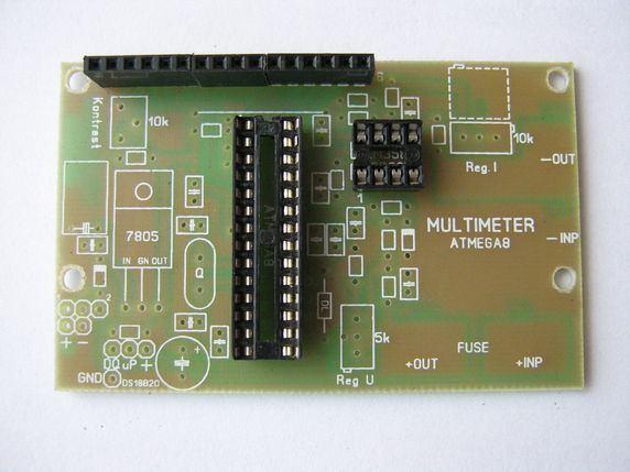
2 MULTIMETER - ATMEGA8 Piotr Bryl SP2DMB sp2dmb@gmail.com Measurement: U, I, P, Ah U, I, P, Ah, kwh for Ham s shack - to wind turbine, solar panels PARAMETERS: - voltage 30V (50Vmax), resolution 0,05V - current version - current 25A, res. +/- 0,1A 3A, res. +/- 0,01A - power 750W max, res. 1W 8A, res. +/-0,02A - 999Ah, res. 0,1Ah 25A, res. +/- 0,1A - 999kWh, res. 0,1kWh - power 750W max, res. 0,1W - 99Ah, res. 0,001Ah This project is for the construction of a simple multimeter with ATMEGA8 microprocessor. In addition on the board there is a place for the temperature sensor DS18B20. PCB allows the construction of a meter to measure voltage, current, power, amp hours, kilowatt hours and the temperature. In addition, the plate pins are available that can be used to control such relays buttons. PCB is ideal for your own projects and learn programming processors! The construction is traditional THT. Dimensions: 80x50mm. The PCB is onesided, plated with solder mask and component assembly drawing.
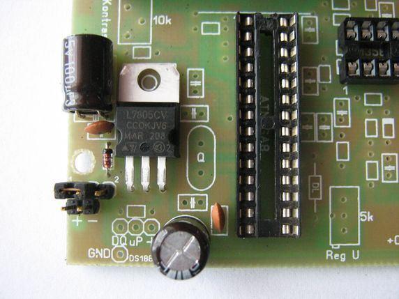
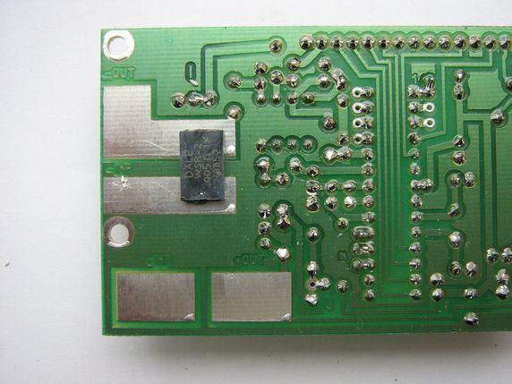
3 DESCRIPTION 1 Power supply Power supply of multimeter is on the 7805 controller based (TO220) This is because of the fact that the maximum voltage supplied system, can be up to 35V. At the beginning of the track is a 1N4148 diode, which protects the system against reverse connection of power supply. The minimum supply voltage is 8V. A tile can be supplied in two ways. With an external power supply, the switch SW1 is in position 1 The second way is to capture the power supply voltage source device - the so-called. Common power. SW1 is then in position 2 For measurements below 7.5 V, use an external power supply (item 1 SW1) 2 Processor The meter uses the processor ATMEGA8-16PU. It works together with external 8MHz quartz. On the board are additional pins that are used for programming (1- RST, 7-5 V, 17-MOSI, MISO SCK, minus the weight). Available pins are: PD0, PD1, PC5, PC4, PC3 and PC2. The reference voltage is 5V and is applied to the CPU by 100uH choke. The processor is mounted on the stand DIL28. Setting the fuse bits: CKSEL: 1111:1111, 0CKOPT: 0 3 Display Used typical LCD display 2x16 characters. This amount is sufficient to show the various types of measured values. The display device driver must be compatible with the HD The diagram given for the design, configuration pins to display. Resistor R10 limits the current supplied to the display backlighting. Potentiometer P3-10k set the contrast. Before connecting the power to set the slider in the middle. After connecting to adjust in order to obtain a clear view characters. Display dimensions: 80 x 36mm. 4 Voltage measurement. Measured voltage reaches the divider R3, P2, R4. Helipot type potentiometer is used to adjust the voltage value displayed properly. For calibration, use a another digital meter. The displayed value should be the same on both gauges. To processor can not be provided a voltage higher than 5V. Therefore, in the voltage measurement circuit is diode Zener 5V1 which cuts voltage greater than this value. It follows that, we can do measurement with this resistor divider to 50V. However, in this case supply of the multimeter by switch SW1 position 2 is prohibited because to stabilizer will come in voltage greater than 35V! The measured voltage goes to the ADC input - 23 pin. 5 Current measurement Here is applied technical method, that is measurement voltage on the resistor, through which current flows. I= U/R The measurement is taken at the track ground power unit. Measuring Resistors R11 and R12 are soldered SMD and are from the paths (dotted line in the diagram assembly). The voltage drop is given by the resistor R6 to the input of operational amplifier
4 LM358 or MCP607. Amplification is in the range G = 6 to 15. Amplified tension goes to the ADC input processor PC1 - pin 24 6 Schematic diagram of the MULTIMETER
. + INP - plus here is connected with the power supply.")
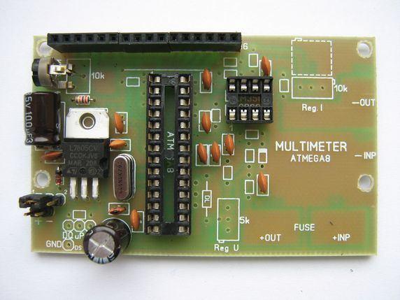
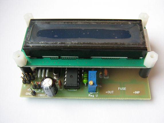
5 7 Installation diagram: * - current version 8 Connect the multimeter to the power measurement. The measured voltage and current connected from the tracks. In the picture above you will find connecting pads - dotted line (they are from the bottom). + INP - plus here is connected with the power supply. It passes through the fuse F1 to the + OUT and then to the receiver -INP - that we give less of power - it is the weight. -OUT - output minus the power supply to the receiver In the case of engine power, there may be interference with the microprocessor. 9 Temperature measurement Measurement of temperature is possible. At the bottom of the left side (see installation diagram) are goldpins to connect the sensor DS18B20. The signal should be given to the free port of the microprocessor. You can use another sensor, but you should pay attention to the correct connection of power supply and signal output. INSTALLATION NOTES Due to the low power consumption by MULTIMETER, 7805 Stabilizer does not require refrigeration.
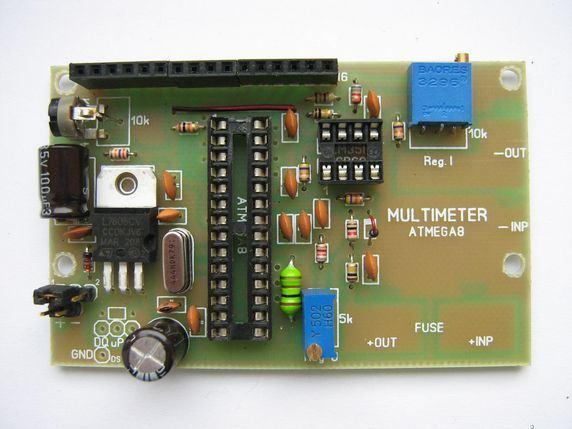
6 Electrolyte C3-100uF mounted in a horizontal position. On the assembly scheme shown in broken lines potentiometer P1. If we do not have it in the version of the 3296X (the knob on the side), you can solder the 3296W version. The pins should be bend 90 degrees and mounted horizontally. Over the processor's patch. It provides a 5V voltage operational amplifier and illumination matrix. For IC is best to use the stand. This will facilitate their removal in case of damage. Display combine with a PCB with a connector HEADER 1x16 - plug + socket. In addition, we combine the four screws from the display board. In addition, we use spacers 12mm in length. The protruding screw (for display) fix another sleeve with internal threads M3 with a length of 6-8mm. The bush will allow us to install the meter to the chassis. For power, access to inputs microprocessor and sensor are used connectors type goldpin. The executed model is using car fuse. Female connectors soldered to the board. These pads + + INP and OUT. Connectors must be cut off and put a fuse. Then soldered to the board. ACCURACY OF MEASUREMENTS Accuracy is dependent on the applied processor and an operational amplifier and a resistor. PROCESSOR - like any AVR shows errors in the calculation and the writing of the program should be taken into account. When testing the finished appliance make adjustments in the program. The applied reference voltage on the meter measurement resolution imposed on us. 1024bit = 5V, which gives V / bit AMP - current measurement Can be successfully used the popular LM358. But we must remember that he is saddled with a large offset at the start sheet. What does that mean? If we measure the very small voltage, they will not be equally amplified. The output voltage is not adequate to set the gain. Practice shows that the linear LM358 begins work on ok.10mv at the amplifier input. So the voltage below 10mV amplified e.g 10 times do not show the correct value. Moreover, the power amplifier 5V, it can be strengthened voltage to a maximum of 3.6 V. This means that the maximum input voltage is 0.36 V. The calculations assume 3V. Non-linearity of the amplifier can be avoided in two ways. Programmatically - use if an amendment to the output voltage of the amplifier and hardware. The measurement accuracy of the block affects the final result, not only the displayed power, but the power supplied and taken ampere! Correction of hardware. Building a measure we must assume its scope. Operational amplifier works measuring resistor R11 (R12). Below is an example of how to correctly choose the desired input range span and thus maximize accuracy (resolution ADC when VREF = 5V).
7 Assumptions: Current measurement up to 3A. Maximum input voltage to 0.3 V amplifier (Uwyj. = 3V, G = 10) From Ohm's Law: U = R x I R = V / I is R = 0.1 ohm Power resistor is: P = R x I ^ 2 P = 0.1 x 9 = 0.9 W Heat emission affects the accuracy of measurement and we need to ensure stable operation of the resistor. For this purpose, the resistor must be used more powerful. Available in SMD are 3D and so you must use the meter. The amplifier MCP607 is an order of magnitude better performance and works well with smaller input voltages. However, you must always seek to maximize the resolution of the ADC in ATMEGA8. NOTES FOR PROGRAMMING The following listing must include a written program. It contained herein LCD control configuration used on the board: Config Lcd = 16 * 2 Config Lcdpin = Pin = Portd.5 DB4, DB5 = Portd.6, DB6 = Portd.7, Db7 = PORTB.0, E = Portd.3, Rs = PORTD.2 Video on You Tube: ASSEMBLY INSTRUCTIONS An integral part of the meter is ATMEGA8 processor and LM358 operational amplifier. The program in the processor is configured to proper amplifier. Installation and commissioning Installation of the unit, perform the installation diagram. Before inserting the chip stand and display, connect voltage to goldpins "Plus" and "Minus". Scope of supply: V with respect to ground. Contacts SW1, normally are set to supply additional external. Check the voltage on leg 7 ATMEGA-i and leg 8 - operational amplifier. It should be about 5V. Disconnect voltage and load integrated circuits as terminals. Replace the display. Reconnect the tension. Potentiometer P3-10k set the contrast of the display. Connect the voltage source, which will be measured. The display will show the voltage "U". Another measure we measure the voltage source. Display on the meter to adjust the potentiometer P2 - helipot.

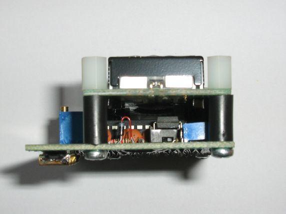
8 No-load current indication should be 0.00 A. Potentiometer P1 - helipot (under the display) to adjust the indication to that value. The exact adjustment of current measurement proceed as follows. The output meter connected in series: a light bulb and an ammeter. We make an adjustment potentiometer P2 current indications. They must be the same on LCD 2x16 and the ammeter. Top adjustment made in the mid range. For example, 3A range - Adjustable at 1.5 A, the range 8A - adjustable to 4A, etc. Due to the non-linearity of the CPU (resolution) and the amplifier display may have slight variations in readings. Precise setting voltage and current readings is essential for the indication of measuring power supplied and the number of ampere-hours taken by the receiver. Reversing the test voltage can damage the system! Use a fuse appropriate for the range! The display is mounted on the spacer sleeves. Internal threaded bushings, provide a simple way for the installation of such a power supply or charger. Ready MULTIMETER (size: 80x50x27mm) VIDEO on YouTube:
9
10
11
12


13 For DC power supply: For wind turbine, solar panels: If You need!
14 Component list C1,C2,C7,C8,C9, C10,C11,C12, C13,C14 = 10 x 100n C3,C4 = 2 x 100µ C5,C6 = 2 x 33p D1 = 1 x 1N4148 D2 = 1 x 5,1V IC1 = 1 x ATMEGA8 DIL-28 = 1 x Goldpin = 11 x 1 L1 = 1 x 100µH F goldpin = 16 x 1 M goldpin = 16 x 1 LCD 16*2 HD44780= 1 x P1 helip. P2 helip. P3 trim. Q = 1 x 10k = 1 x 5k = 1 x 10K = 1 x 8MHz R2 = 1 x 6,8k R4 = 1 x 8,2k R8 = 1 x 1k R9 = 1 x 27K R10 = 1 x 510 R13 = 1 x 10k R14 = 1 x 4,7k R1,R3 = 2 x 100k R11,R12 = 2 x *see documentation R5,R6,R7 = 3 x 47k SW1 = 1 x 1 UM Goldpin = 3 x 1 T sensor1* = 1 x DS18B20 - option Goldpin = 4 x 1 U1 DIL8 = 1 x LM358, MCP607 = 1 x VR1 = 1 x 7805 Goldpin. = 2 x 1
RF amplifier 70MHz on RA30H0608M
 RF amplifier 70MHz on RA30H0608M Peter SP2DMB 19.08.2014r. sp2dmb@gmail.com www.sp2dmb.blogspot.com www.sp2dmb.cba.pl The availability of a hybrid power amplifier allows easy to built RF power amplifier
Warm Tube Clock. Before we start, please make sure that you have all required parts that come for the main board :
 Warm Tube Clock Assembly Instructions for the main board Introduction Congratulations on your purchase of OSH Nixie Tube Clock. In this document you will see all steps you need to follow in order to successfully
Penrose Quantizer Assembly Guide
 Penrose Quantizer Assembly Guide Schematic and BOM The schematic can be found here: www.sonic-potions.com/public/penrosequantizerschematic.pdf The BOM is available at google docs: Link to BOM Prepare the
TS500 Assembly guide. Soldering. TS500 Assembly guide Main PCB 1. Diodes. Document revision 1.2 Last modification : 17/12/16
 TS500 Assembly guide Safety warning The kits are main powered and use potentially lethal voltages. Under no circumstance should someone undertake the realisation of a kit unless he has full knowledge about
DDS VFO 2 CONSTRUCTION MANUAL. DDS VFO 2 Construction Manual Issue 1 Page 1
 DDS VFO 2 CONSTRUCTION MANUAL DDS VFO 2 Construction Manual Issue 1 Page 1 Important Please read before starting assembly STATIC PRECAUTION The DDS VFO kit contains the following components which can be
Ten Tec DDS Board Assembly Procedure
 05 May 2014 Ten Tec DDS Board Assembly Procedure You will find a photo of a completed board at the end of these instructions. Refer it whenever clarification is required. 1. AD9835 Attachment If you purchased
LA502 Assembly guide Main PCB Resistors - (2)
") LA502 Assembly guide Safety warning The kits are main powered and use potentially lethal voltages. Under no circumstance should someone undertake the realisation of a kit unless he has full knowledge about
LA502 Assembly guide Safety warning The kits are main powered and use potentially lethal voltages. Under no circumstance should someone undertake the realisation of a kit unless he has full knowledge about
KN-Q10 Assembly Manual
 KN-Q10 Assembly Manual Translated by Adam Rong, BD6CR/4 with permission from Ke Shi, BA6BF Edited by Stephen, VK2RH Revision B, Oct 14, 2010 Thank you for purchasing the KN-Q10 4 Band SSB/CW Dual Mode
MICROGRANNY v2.1 - Assembly Guide
 last update: 9. 5. 2017 MICROGRANNY v2.1 - Assembly Guide bastl-instruments.com INTRODUCTION Welcome to the assembly guide for the MicroGranny kit. MicroGranny is a monophonic granular sampler by Bastl
HT-1A Dual Band CW QRP Transceiver. Kit Building Instructions
 HT-A Dual Band CW QRP Transceiver Kit Building Instructions Rev B, July 8, 08 Designed by BD4RG Exclusively distributed by CRKITS.COM and its worldwide distributors Join the group http://groups.io/g/crkits
HF Amateur SSB Receiver
 HF Amateur SSB Receiver PCB Set for radio club project http://rhelectronics.net PCB for DIY HF Amateur SSB Receiver 20M The receiver is a simple syperheterodyne type with quartz crystal filter. The circuit
CW-ADD. Universal CW Adapter for SSB Transceivers. Assembly manual. Last updated: October 1,
 CW-ADD Universal CW Adapter for SSB Transceivers Assembly manual Last updated: October 1, 2017 ea3gcy@gmail.com Updates and news at: www.ea3gcy.com Thanks for building the Universal CW Adapter kit CW-ADD
DEC-001 Installation Instructions
 DEC-001 Installation Instructions Skill Level: The installation of this assembly requires a medium level of expertise in working with modern electronic equipment. The use of appropriate tools, correct
8x8 Red Blue Green Yellow Audio Indicator
 8x8 Red Blue Green Yellow Audio Indicator 1. Introduce. 1>. Working voltage: 5V. 2>. PCB size: 75*45mm. 3>. There are four fixed mounting holes on PCB. 4>. It is no need for filter circuit. It can driver
LITTLE NERD v1.1 Assembly Guide
 last update: 9. 3. 2016 LITTLE NERD v1.1 Assembly Guide bastl instruments.com INTRODUCTION This guide is for building Little Nerd module from Bastl Instruments. It is good to have basic soldering skills
Starving Student II. Starving Student II. SS2 guide. Written By: 6L guides.diyaudio.com/ Page 1 of 24
 SS2 guide Written By: 6L6 2019 guides.diyaudio.com/ Page 1 of 24 INTRODUCTION This is a build guide for the hybrid headphone/pre-amplifier. You can buy a kit at the SSII product listing on the diyaudio
List of Items Available in the Laboratory the Lab
 List of Items Available in the Laboratory the Lab Category Component 555 Timer $0.30 5V Relay $3.50 74xxx Series IC Chip $0.30 Battery - 12V (rechargeable Lead-acid type) $16.00 Battery - 6V (rechargeable
Ocean Controls KT-5198 Dual Bidirectional DC Motor Speed Controller
 Ocean Controls KT-5198 Dual Bidirectional DC Motor Speed Controller Microcontroller Based Controls 2 DC Motors 0-5V Analog, 1-2mS pulse or Serial Inputs for Motor Speed 10KHz, 1.25KHz or 156Hz selectable
NEW DESIGN***DEM Part Number FRS***NEW DESIGN Low power 144 MHz Transverter for the Flex Radio System SDR-1000 Operating Specifications:
 NEW DESIGN***DEM Part Number 144-28FRS***NEW DESIGN Low power 144 MHz Transverter for the Flex Radio System SDR-1000 Operating Specifications: Operating Voltage: 12.0-15.5 VDC, 13.8 nominal Current Drain:
Digital temperature controllers
 Digital Temperature Controller Using Thermocouple sunil kumar Adeeb Raza Digital temperature controllers are essential for temperature measurement and control of instrumentation in industries. These are
Beta-test ED1 PCB installed in I0CG s K1
 K1 SSB Modification (Ed.2) This description provides the receiver (RX) modifications, assembly, alignment and operation as a first step. In a second step you can add the remaining transmitter (TX) modifications,
ABC V1.0 ASSEMBLY IMPORTANT!
 ABC V1.0 ASSEMBLY Before starting this kit, prepare the following tools: Soldering iron (15-20W will do), flush cutters, no.2 hex screwdriver or allen key and phillips screwdriver. Also briefly go through
SDR Cube Transceiver Online Assembly Guide
 SDR Cube Transceiver Online Assembly Guide Detailed construction notes for building and testing each of the SDR Cube kit modules Home Bill of Materials I/O Board Controls Board DSP Board Softrock SR-Base
About LC Meter This is one of the most accurate and simplest LC inductance / capacitance Meters that one can find, yet one that you can easily build y
 Home Electronic Store Electronic Blog Electronic Schematics Tutorials Downloads Lin Very Accurate LC Meter based on PIC16F84A IC. LC Meter Part's List: 2x 1K 2x 6.8K 1x 47K 3x 100K 1x 10K POT 2x 10pF 1x
IPR LA-3 KIT last update 15 march 06
 IPR LA-3 KIT last update 15 march 06 PART-2: Audio Circuitry CIRCUIT BOARD LAYOUT: Power and Ground Distribution Now that your power supply is functional, it s time to think about how that power will be
Laboratory PSU. Applications *Laboratories and test benches * Powering mobile radio equipment. * Precision charging of batteries
 0A. OV Laboratory PSU * Output voltage variable from 0 to +0V (Fine adjustment over V) * Variable current limit from 0 to OA * LED current limit indicator * Output short circuit protected Maximum 0. 5V
Bill of Materials: PWM Stepper Motor Driver PART NO
 PWM Stepper Motor Driver PART NO. 2183816 Control a stepper motor using this circuit and a servo PWM signal from an R/C controller, arduino, or microcontroller. Onboard circuitry limits winding current,
Analog Technologies. Auto Iron ATAS80
 Figure 1. The Photo of main machine Figure 2. Photo of MAIN FEATURES Large LCD screen display, convenient for adjusting Anti-static function to protect precise chip soldering Quick temperature rise Unit
DIY Function Generator XR2206
 DIY Function Generator XR2206 20Hz 100KHz http://radiohobbystore.com Components List: Resistors: R1, R2 1% Metal Film 5K1 R4 1% Metal Film 10K R5 1% Metal Film 3K R10 5% Carbon Film 10R R3, R9 Potentiometer
N3ZI Kits General Coverage Receiver, Assembly & Operations Manual (For Jun 2011 PCB ) Version 3.33, Jan 2012
 Version 3.33, Jan 2012") N3ZI Kits General Coverage Receiver, Assembly & Operations Manual (For Jun 2011 PCB ) Version 3.33, Jan 2012 Thank you for purchasing my general coverage receiver kit. You can use the photo above as a
N3ZI Kits General Coverage Receiver, Assembly & Operations Manual (For Jun 2011 PCB ) Version 3.33, Jan 2012 Thank you for purchasing my general coverage receiver kit. You can use the photo above as a
Line-Following Robot
 1 Line-Following Robot Printed Circuit Board Assembly Jeffrey La Favre October 5, 2014 After you have learned to solder, you are ready to start the assembly of your robot. The assembly will be divided
High-Impedance Millivoltmeter HF-Level Meter
 Instruction Manual High-Impedance Millivoltmeter HF-Level Meter Author Hans-Peter Prast, DL2KHP Version 1.2 page 1 of 11 1. Preliminary note The device was developed for high precision measurements of
Copyright 2012, R. Eckweiler & OCARC, Inc. Page 1 of 5
 Heathkit of the Month #42: by Bob Eckweiler, AF6C Heathkit HD-1422-A Antenna Noise Bridge Introduction: If you work with antennas, an antenna noise bridge can be a very handy tool. Table 1 lists some of
FC3 Project Info: PIC18F /500MHZ Frequency Counter & RF Meter. This project is developed for Amateur Radio Community by:
 Fox Delta Amateur Radio Projects & Kits FC3-0915 FC3 Project Info: PIC18F4550 50/500MHZ Frequency Counter & RF Meter This project is developed for Amateur Radio Community by: Antonio Alfinito / I2TZK Dinesh
3. Assembly manual ANALYZING THE PCB'S LCD PCB. Component side: Solder side:
 3. Assembly manual ANALYZING THE PCB'S LCD PCB Component side: Solder side: MAIN PCB Component side: Solder side: ASSEMBLGING THE LCD PCB 1. Resistor R1: 33 Ohm (orange, black, black) 2. 6 Pin female header
Ultimate3S: Multi-mode QRSS/WSPR transmitter kit. PCB Revision: QCU Rev 3
 Ultimate3S: Multi-mode QRSS/WSPR transmitter kit 1. Introduction PCB Revision: QCU Rev 3 Thank you for purchasing this QRP Labs kit. You will also plug in other modules. You need to download assembly instructions
MP573 Assembly guide. Soldering. MP573 Assembly guide PCB split PCB split. Document revision 2.2 Last modification : 22/08/17
 MP573 Assembly guide Safety warning The kits are main powered and use potentially lethal voltages. Under no circumstance should someone undertake the realisation of a kit unless he has full knowledge about
BMC052. Chordizer Last updated
 BMC052. Chordizer Last updated 8-27-2017 If you have any questions, or need help trouble shooting, please e-mail Michael@Bartonmusicalcircuits.com I Overview/Controls/Inputs/Outputs II Schematic III Construction
The Guitar Chord Learning System
 The Guitar Chord Learning System Calvin A. Sessions Hardware Description April 19, 2005 Western Washington University Electronics Engineering Technology ETEC 474, Professor Morton INTRODUCTION The Guitar
Easy Transmitter. Support ETX_REV5_Manual V2.7 Revised
 Easy Transmitter Introduction The Easy Transmitter kit from qrpkits.com provides a basic, crystal controlled transmitter with VXO tuning to provide a small tuning range around the crystal frequency. It
Fox Delta FC Amateur Radio Projects & Kits. FC3 Project Info: PIC18F /500MHZ Frequency Counter & RF Meter
 Fox Delta Amateur Radio Projects & Kits FC3-0812 FC3 Project Info: PIC18F4550 50/500MHZ Frequency Counter & RF Meter This project is developed for Amateur Radio Community by: Antonio Alfinito / I2TZK Dinesh
Read This Page First
 Read This Page First If you are reading this you know the manuals are always available at QRPKITS.com. This is version 8.0 of the manual dated 4/27/2016. There is no need to print out the whole assembly
Building a Bitx20 Version 3
 Building a Bitx20 Version 3 The board can be broken into sections and then built and tested one section at a time. This will make troubleshooting easier as any problems will be confined to one small section.
EET 150 Introduction to EET Lab Activity 12 Temperature Sensor Amplifier Project
 Required Parts, Software and Equipment Parts EET 150 Introduction to EET Lab Activity 12 Temperature Sensor Amplifier Project Figure 1 Flasher Circuit Component /alue Quantity LM741 OP AMP Integrated Circuit
The ROSE 80 CW Transceiver (Part 1 of 3)
") Build a 5 watt, 80 meter QRP CW Transceiver!!! Page 1 of 10 The ROSE 80 CW Transceiver (Part 1 of 3) Build a 5 watt, 80 meter QRP CW Transceiver!!! (Designed by N1HFX) A great deal of interest has been
Build a 5 watt, 80 meter QRP CW Transceiver!!! Page 1 of 10 The ROSE 80 CW Transceiver (Part 1 of 3) Build a 5 watt, 80 meter QRP CW Transceiver!!! (Designed by N1HFX) A great deal of interest has been
ALX-SSB Transceiver Kit Assembly Manual
 ALX-SSB Transceiver Kit Assembly Manual 20 August 2018 REV A Transceiver This radio is based on the popular CS-Series SSB Transceiver Kit developed by Adam Rong, BD6CR/4 CRKITS.com. Thanks to B. Bartosh
Pingable Envelope Generator
 Pingable Envelope Generator Kit Builder's Guide for PCB v1.0.3 4mspedals.com PEG This guide is for building a Pingable Envelope Generator (PEG), which is an intermediate-level kit. You should be confident
POWER AMPLIFIER SERVICE MANUAL CONTENTS
 POWER AMPLIFIER CONTENTS Performance Specifications... 2 Notes... 2 Rear Panel... 3 Section Location... 5 Block Diagram... 6 Interconnection Diagram... 7-8 Input Schematic and PCB... 9-12 Heatsink 1-Channel
H BRIDGE INVERTER. Vdc. Corresponding values of Va and Vb A+ closed, Va = Vdc A closed, Va = 0 B+ closed, Vb = Vdc B closed, Vb = 0 A+ B+ A B
 1. Introduction How do we make AC from DC? Answer the H-Bridge Inverter. H BRIDGE INVERTER Vdc A+ B+ Switching rules Either A+ or A is always closed, but never at the same time * Either B+ or B is always
Crystal oscillator Phase accumulator Look-up table D/A converter
 Direct Digital Synthesis (DDS) is one of the more prevalent methods used to generate a frequency agile signal today. The material in the following explanation was taken from www.ehb.itu. edu.tr/~eepazarc/ddstu
Construction notes for the symmetrical 400 watt amplifier
 Construction notes for the symmetrical 400 watt amplifier Introduction The symmetrical amplifier is an update of one of my designs, which appeared in the Australian electronics magazine Silicon Chip in
Step by Step Building PJ meter ARDF Receiver Kit. CRKITS.COM August 5, 2013
 Step by Step Building PJ-80 80-meter ARDF Receiver Kit CRKITS.COM August 5, 2013 What is ARDF? ARDF is the abbreviation of Amateur Radio Direction Finding, or so called Fox Hunting. If you are looking
"Nighthawk" CW Transceiver Kit V3.1
 "Nighthawk" CW Transceiver Kit V3.1 Brief Introduction The "Nighthawk" CW transceiver is based on a well-known US design by Dave Benson, K1SWL at Small Wonder Labs. Its classic design includes a standard
Instructions for Building the Pulsed Width Modulation Circuit. MC-12 (DC Motor Controller or PWM) From Electronic Light Inc. (revised kit 10/03/08)
 From Electronic Light Inc. (revised kit 10/03/08)") Instructions for Building the Pulsed Width Modulation Circuit MC-12 (DC Motor Controller or PWM) From Electronic Light Inc. (revised kit 10/03/08) Congratulations on your purchase of the MC-12 DC Motor
Instructions for Building the Pulsed Width Modulation Circuit MC-12 (DC Motor Controller or PWM) From Electronic Light Inc. (revised kit 10/03/08) Congratulations on your purchase of the MC-12 DC Motor
AVL-10000T AUDIO VIDEO LINK TRANSMITTER TECHNICAL MANUAL
 AVL-10000T AUDIO VIDEO LINK TRANSMITTER TECHNICAL MANUAL Document : AVL-10000T Version: 1.00 Author: Henry S Date: 25 July 2008 This module contains protection circuitry to guard against damage due to
New Life for the AM6154 and AM6155 John, W1AN 29 July, 2014
 New Life for the AM6154 and AM6155 John, W1AN 29 July, 2014 There are numerous sources for conversion information and modifications that have been shared over the years for the FAA AM6154 and AM6155 amplifiers
UNITED MOTORS SERVICE. DIVISION OF GENERAL MOTORS CORPORATION General Offices - Detroit AUTO RADIO BULLETIN
 UNITED MOTORS SERVICE DIVISION OF GENERAL MOTORS CORPORATION General Offices - Detroit AUTO RADIO BULLETIN Bulletin 6D-848 Chevrolet 986515 Page 1 SUBJECT: SERVICE INSTRUCTIONS CHEVROLET CUSTOM DELUXE
Cricket 80a Assembly Manual v Copyright David Cripe NM0S The 4 State QRP Group
 Cricket 80a Assembly Manual v. 1.0 Copyright 2017 David Cripe NM0S The 4 State QRP Group Introduction Thank you for purchasing a CRICKET 80a Transceiver. We hope you will enjoy building it and find it
V. 3. Assembly Guide. ShortWave Receiver Kit Double Super 10.7Mhz /455Khz SSB/CW/AM 5.9 Mhz to 8.1 Nominal. SW-Receiver
 Assembly Guide V. 3 JUNIOR 1 ShortWave Receiver Kit Double Super 10.7Mhz /455Khz SSB/CW/AM 5.9 Mhz to 8.1 Nominal SW-Receiver Table of contents PAGE TITLE PAGE JUNIOR 1 General Description I1 JUNIOR 1
S&T GeoTronics LLC Open DSKY with AGC Assembly Instructions
 S&T GeoTronics LLC Open DSKY with AGC Assembly Instructions First, make sure you have all the required components: HARDWARE Qty Item 1 DSKY PCB v1.0d 1 Arduino Nano 1 VA RTC 1 IMU 1 Buck StepDown 1 SKM53
DSSIU-6-1U. Dedicated 6-channel system interface unit for ultra-stable, high precision fluxgate technology DS series current transducers.
 DSSIU-6-1U Dedicated 6-channel system interface unit for ultra-stable, high precision fluxgate technology DS series current transducers. Powers up to 6 x DS50 to DS2000 at the same time. Supports calibration
Ameritron ALS-600 Retrofit ALS-600-LPF Assembly Manual
 Ameritron ALS-600 Retrofit ALS-600-LPF Assembly Manual FEATURES Automatic band change based on TX frequency. PIN diode QSK RX/TX switch. Temperature controlled FAN for quiet operation. RS-232 serial port
DeluxeArcade. JAMMA Fingerboard. Introduction. Features. Version 1.1, November 2014 Martin-Jones Technology Ltd
 DeluxeArcade JAMMA Fingerboard Version., November 204 Martin-Jones Technology Ltd http://www.martin-jones.com/ Introduction The Deluxe Arcade JAMMA Fingerboard is designed to make adapting non-jamma arcade
Bitx Version 3 Linear Amplifier Assembly
 Bitx Version 3 Linear Amplifier Assembly The power supply section has 2 options. 1 - AC input and a higher voltage on the IRF510 and +12 volts to the bitx. 2 - +12 volts applied to both the final and the
FROM SCHEMATIC TO VEROBOARD
 FROM SCHEMATIC TO VEROBOARD The circuit of a bench amplifier utilising a LM386 linear (integrated circuit) IC and a few other components is used for this tutorial. The schematic is shown below: First a
MAINTENANCE MANUAL MDX POWER AMPLIFIER BOARDS 19D904792G2 ( MHz) 19D904792G1 ( MHz) 19D904792G3 ( MHz)
 19D904792G1 ( MHz) 19D904792G3 ( MHz)") MAINTENANCE MANUAL MDX POWER AMPLIFIER BOARDS 19D904792G2 (403-440 MHz) 19D904792G1 (440-470 MHz) 19D904792G3 (470-512 MHz) TABLE OF CONTENTS Page DESCRIPTION... 1 CIRCUIT ANALYSIS... 1 SERVICE NOTES...
MAINTENANCE MANUAL MDX POWER AMPLIFIER BOARDS 19D904792G2 (403-440 MHz) 19D904792G1 (440-470 MHz) 19D904792G3 (470-512 MHz) TABLE OF CONTENTS Page DESCRIPTION... 1 CIRCUIT ANALYSIS... 1 SERVICE NOTES...
Stand Alone VXO (SAVXO) Assembly Manual Manual Version 1.0B_
 Assembly Manual Manual Version 1.0B_") Stand Alone VXO (SAVXO) Assembly Manual Manual Version.0B_0-6-0 Designed by: Jim Kortge, K8IQY Kitted & Sold by: 4 State QRP Group Copyright: 0 Forward Thank you for purchasing a 4 State QRP Group Stand
Stand Alone VXO (SAVXO) Assembly Manual Manual Version.0B_0-6-0 Designed by: Jim Kortge, K8IQY Kitted & Sold by: 4 State QRP Group Copyright: 0 Forward Thank you for purchasing a 4 State QRP Group Stand
Construction Manual 6m-Linear-Transverter XV6/10
 Construction Manual 6m-Linear-Transverter XV6/10 Holger Eckardt DF2FQ Kirchstockacherstr. 33 D-85662 Hohenbrunn 2606 Technical data exciter frequency: 28... 30 MHz RF frequency: 50... 52 MHz supply voltage:
ESE141 Circuit Board Instructions
 ESE141 Circuit Board Instructions Board Version 2.1 Fall 2006 Washington University Electrical Engineering Basics Because this class assumes no prior knowledge or skills in electrical engineering, electronics
Banggood IRF 530 PA Kit Build Instructions. Collated and Edited by 4Z4TJ. Ver. 1.4 February 2016
 DIY 45W SSB HF Linear Power Amplifier Amateur Radio Transceiver Shortwave Radio Development Board Kit This document is an attempt to put the manual supplied for download on the seller s website into more
M328 version ESR inductance capacitance meter multifunctional tester DIY
 M328 version ESR inductance capacitance meter multifunctional tester DIY About transistor Multifunction Tester: The tester uses 3.7V rechargeable lithium battery (battery model: 14500) powered portable
Introduction to Electronic Equipment
 Introduction to Electronic Equipment INTRODUCTION This semester you will be exploring electricity and magnetism. In order to make your time in here more instructive we ve designed this laboratory exercise
nrf905-evboard nrf905 Evaluation board PRODUCT SPECIFICATION GENERAL DESCRIPTION
 nrf905 Evaluation board nrf905-evboard GENERAL DESCRIPTION This document describes the nrf905-evboard and its use with the Nordic Semiconductor nrf905 Single Chip 433/868/915MHz RF Transceiver. nrf905-
Formal Report of. Project 2: Advanced Multimeter using VHDL
 EECE 280 & APSC 201 Formal Report of Project 2: Advanced Multimeter using VHDL Group: B7 Kelvin A Jae Yeong B Amelia C Chao J Rohit S Instructor: Dr. Joseph Yan (EECE 280) Dr. Jesus Calvino (EECE280) Mrs.
12kHz LIF Converter V2.43 9Mhz version
 12kHz LIF Converter V2.43 9Mhz version Please Note: This document supersedes all previously released documents and drawings on the LIF subject. This is the latest and most up-to-date document at this time.
Digital mw meter. 1. Functioning VHF COMMUNICATIONS 2/2003. Alexander Meier, DG6RBP
 Alexander Meier, DG6RBP Digital mw meter The revised version of a digital mw meter [1] is described below. Almost any diode detectors not needing a Townsend current can be used as sensors for this equipment.
LED S METER CONSTRUCTION MANUAL. LED S meter Construction Manual Issue 1.0 Page 1
 LED S METER CONSTRUCTION MANUAL LED S meter Construction Manual Issue 1.0 Page 1 Important Please read before starting assembly STATIC PRECAUTION The LED S Meter kit contains components which can be damaged
Circuit and wiring connections as follows:
 Fault Indication via TTL compatible open collector output (can be used for additional protection circuitry or for our upcoming electronic choke PSU PCB) multiple mounting holes for easy mounting Can be
BP-1A. Band-Pass variable filter continuous tuning from 3 to 30MHz. For analogue or software-defined receivers (SDR) Assembly manual
 Assembly manual") BP-1A Band-Pass variable filter continuous tuning from 3 to 30MHz. For analogue or software-defined receivers (SDR) Assembly manual Last updated: December 1, 2017 ea3gcy@gmail.com Updates and news at:
BP-1A Band-Pass variable filter continuous tuning from 3 to 30MHz. For analogue or software-defined receivers (SDR) Assembly manual Last updated: December 1, 2017 ea3gcy@gmail.com Updates and news at:
Assembly and Installation Instructions for White Oak Audio Design TM-1001 LED board
 Thank you for purchasing White Oak Audio Design s TM-1001 Upgrade LED Light Board. White Oak Audio Design products are meticulously engineered and tested to ensure a direct drop in fit with your tuner.
SERVICE MANUAL 2 CHANNEL POWER AMPLIFIER GFA-5400
 SERVICE MANUAL 2 CHANNEL POWER AMPLIFIER GFA-5400 TABLE OF CONTENTS Introduction...1 Version 1 vs. Version 2........ 1 Test Procedures............. 1 Parts List...2 Specifications...6 Chassis Layout...............
MFJ-249B HF/VHF SWR ANALYZER
 TABLE OF CONTENTS MFJ-249B... 2 Introduction... 2 Powering The MFJ-249B... 3 Battery Installation... 3 Alkaline Batteries... 3 NiCd Batteries... 4 Power Saving Mode... 4 Operation Of The MFJ-249B...5 SWR
VOLUME AND TONE CONTROL - PREAMPLIFIER K8084
 VOLUME AND TONE CONTROL - PREAMPLIFIER K8084 When using one of our amplifiers (big or small), you always need a volume control and preferably also a tone control H8084IP-1 Features & specifications When
DSSIU-6-1U-V. Features VOM:
 Fully configurable dedicated 1U high 6-channel system interface unit for ultra-stable, high precision fluxgate technology DS series current transducers. Powers up to 6 x DS50 to DS2000 at the same time.
EMG Sensor Shirt. Senior Project Written Hardware Description April 28, 2015 ETEC 474. By: Dylan Kleist Joshua Goertz
 EMG Sensor Shirt Senior Project Written Hardware Description April 28, 2015 ETEC 474 By: Dylan Kleist Joshua Goertz Table of Contents Introduction... 3 User Interface Board... 3 Bluetooth... 3 Keypad...
REPAIRING THE RM KL400 LINEAR AMPLIFIER.
 REPAIRING THE RM KL400 LINEAR AMPLIFIER. Les Carpenter G4CNH December 2012 Page 1 of 20 The following is a step by step guide to fixing your KL400 amplifier. Each part will be individually tested up to
Pacific Antenna Easy Transmitter Kit
 Pacific Antenna Easy Transmitter Kit Introduction The Easy Transmitter kit from qrpkits.com provides a crystal controlled transmitter with VXO tuning. The circuit consists of a N3904 based crystal oscillator
Instructions for Building the Pulsed Width Modulation Circuit. MC-12 (DC Motor Controller or PWM) From Electronic Light Inc. (revised kit 5/08)
 From Electronic Light Inc. (revised kit 5/08)") Instructions for Building the Pulsed Width Modulation Circuit MC-12 (DC Motor Controller or PWM) From Electronic Light Inc. (revised kit 5/08) Using this circuit for a pulsed DC current to your cell. Do
Instructions for Building the Pulsed Width Modulation Circuit MC-12 (DC Motor Controller or PWM) From Electronic Light Inc. (revised kit 5/08) Using this circuit for a pulsed DC current to your cell. Do
The Skiidometer. Hardware Description By: Adam Lee ; Etec474; Prof. Morton; WWU
 The Skiidometer Hardware Description By: Adam Lee 04.26.2003; Etec474; Prof. Morton; WWU General Description The Skiidometer is a portable meter which serves as a digital companion on the ski slopes. By
DEM Part Number L144-28INTCK 144 MHz Transverter Kit and complete kit
 DEM Part Number L144-28INTCK 144 MHz Transverter Kit and complete kit Power Out: Noise Figure and Gain: DC Power Requirement: 50 mw linear minimum 3.5 db NF nominal, 5 dbg maximum 12-15.5 VDC, 13.8 nominal
K8055N. USB Experiment interface board. Interface your computer with the world using 5 digital in and 8 outputs, 2 analogue in-and outputs.
 Total solder points: 313 Difficulty level: beginner 1 2 3 4 5 advanced USB Experiment interface board K8055N Interface your computer with the world using 5 digital in and 8 outputs, 2 analogue in-and outputs.
Bi-Directional DC Motor Speed Controller 5-32Vdc (3166v2)
") General Guidelines for Electronic Kits and Assembled Modules Thank you for choosing one of our products. Please take some time to carefully read the important information below concerning use of this product.
General Guidelines for Electronic Kits and Assembled Modules Thank you for choosing one of our products. Please take some time to carefully read the important information below concerning use of this product.
The ability to make basic voltage and resistance measurements using a digital multimeter
 Congratulations on your purchase of a new OneShot chassis! The PC01 OneShot combines a rugged enclosure, power supply, and discrete instrument DI in a compact 1/4U package. A few minutes of assembly are
Read This Page First
 Read This Page First If you are reading this you know the manuals are always available at QRPKITS.com. If you have questions contact qrpkits.com@gmail.com There is no need to print out the whole assembly
Assembly Manual V1R2B-Rev1.0D
 Assembly Manual V1R2B-Rev1.0D for 4 State QRP MagicBox - Solid State Transmit/Receive System Designed by: Jim Kortge, K8IQY Copyright 2009-2012 - All rights reserved This system is the result of some brainstorming
AMSynths AM8044 VCF & VCA. Project Notes V2.0
 AMSynths AM8044 VCF & VCA Project Notes V2.0 AMSynths 2013 Rob Keeble Contact: sales@amsynths.co.uk Web Site: www.amsynths.co.uk 18 May 2013 1 Module Description This module is designed around the SSM2044
A digital DC powersupply
 LinuxFocus article number 379 http://linuxfocus.org A digital DC powersupply Abstract: by Guido Socher (homepage) About the author: Guido likes Linux because it is a really good system to develop your
Grounded Grid Plus Vacuum Tube Preamplifier User Manual. Analog Metric
 Grounded Grid Plus Vacuum Tube Preamplifier User Manual Analog Metric Page 2 INTRODUCTION This Grounded Grid Plus preamplifier provides enhanced performance out of the original Grounded Grid design. This
PLANNING YOUR SYSTEM
 INTRODUCTION HERTIAGE amplifiers provide high-performance sound reinforcement for your mobile audio equipment. Its versatility enables compatibility with optional Equalizers, Frequency Dividing Crossover
Laney. CD650Mixer/Amplifier ServiceInformation. PartNumber -SM3041
 Laney CD650Mixer/Amplifier ServiceInformation PartNumber -SM3041 Laney Contents 1.DWG 3044 Service Schematic 2.DWG 2615 MainsWiring 3.DWG 3010 Block Diagram 4.DWG 9324 Preamp DiagramChannel 5.DWG 9324